1
YASKAWA
Series SGDH
MECHATROLINK- APPLICATION MODULE
USER'S MANUAL
MODEL: JUSP-NS115
YASKAWA
MANUAL NO. SIEP C710800 01E
Copyright © 2002 YASKAWA ELECTRIC CORPORATION
All rights reserved. No part of this publication may be reproduced, stored in a retrieval system,
or transmitted, in any form, or by any means, mechanical, electronic, photocopying, recording,
or otherwise, without the prior written permission of Yaskawa. No patent liability is assumed
with respect to the use of the information contained herein. Moreover, because Yaskawa is constantly striving to improve its high-quality products, the information contained in this manual is
subject to change without notice. Every precaution has been taken in the preparation of this
manual. Nevertheless, Yaskawa assumes no responsibility for errors or omissions. Neither is
any liability assumed for damages resulting from the use of the information contained in this
publication.
Overview
About this Manual
This manual provides the following information for the Σ-ΙΙ Series SGMH/SGDH-E
servodrives with a JUSP-NS115 MECHATROLINK-II application module (hereinafter
called the NS115 Module).
• Procedures for installing and wiring the servomotor, SERVOPACK, and NS115 Module.
• Procedures for trial operation of the servodrive.
• Procedures for using functions and adjusting the servodrives.
• Procedures for using the built-in Panel Operator and the Hand-held Digital Operator.
• Ratings and specifications for standard models.
• Procedures for maintenance and inspection.
• MECHATROLINK-II communications specifications for SGDH SERVOPACK
Intended Audience
This manual is intended for the following users.
• Those designing servodrive systems using MECHATROLINK-II
• Those designing Σ-II Series servodrive systems.
• Those installing or wiring Σ-II Series servodrives.
• Those performing trial operation or adjustments of Σ-II Series servodrives.
• Those maintaining or inspecting Σ-II Series servodrives.
Description of Technical Terms
In this manual, the following terms are defined as follows:
• NS115 Module = JUSP-NS115 or JUSP-NS115-E
• Servomotor = Σ-ΙΙ Series SGMAH, SGMPH, SGMGH, SGMSH, or SGMDH servomotor.
• SERVOPACK = Σ-ΙΙ Series SGDH-E SERVOPACK.
• Servodrive = A set including a servomotor and Servo Amplifier.
• Servo System = A servo control system that includes the combination of a servodrive
with a host controller and peripheral devices.
• Online parameters = Parameters that are enabled as soon as they are set.
• Offline parameters = Parameters that are enabled when the control power is turned OFF
and ON again after setting with the Write Non-volatile Parameter command
(PPRM_WR), or those that are set with the control power ON and enabled with the Set
Up Device command (CONFIG).
iii
Indication of Reverse Signals
In this manual, the names of reverse signals (ones that are valid when low) are written with a
forward slash (/) before the signal name, as shown in the following examples:
• /S-ON
• /P-CON
Visual Aids
The following aids are used to indicate certain types of information for easier reference.
EXAMPLE
INFO
IMPORTANT
TERMS
Indicates application examples.
Indicates supplemental information.
Indicates important information that should be memorized, including precautions such as
alarm displays to avoid damaging the devices.
Indicates definitions of difficult terms or terms that have not been previously explained in
this manual.
iv
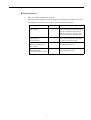
Related Manuals
Refer to the following manuals as required.
Read this manual carefully to ensure the proper use of Σ-ΙΙ Series servodrives. Also, keep
this manual in a safe place so that it can be referred to whenever necessary.
Manual Name
Manual Number
Contents
Σ-II Series SGMH/SGDH
User’s Manual
SIEPS80000005
Provides detailed information on selecting
Σ-II Series Servodrives/Servomotors and
capacities, and detailed information on
installation, wiring, trial operation, using
functions, maintenance, and inspection.
Σ-ΙΙ Series SGMH/SGDM
Digital Operator
Operation Manual
TOE-S800-34
Provides detailed information on the operation of the JUSP-OP02A-2 Digital Operator, which is an optional product.
High-speed Field Network
MECHATROLINK System
User’s Manual
SIE-S800-26.1
Provides detailed information on the
MECHATROLINK system.
High-speed Field Network
SIE-S800-26.2
MECHATROLINK
Servo Command User’s Manual
v
Describes the Servo commands for use in a
MECHATROLINK system.
Safety Information
The following conventions are used to indicate precautions in this manual. Failure to heed
precautions provided in this manual can result in serious or possibly even fatal injury or
damage to the products or to related equipment and systems.
WARNING
CAUTION
Indicates precautions that, if not heeded, could possibly result in loss of life or
serious injury.
Indicates precautions that, if not heeded, could result in relatively serious or minor
injury, damage to the product, or faulty operation.
Even items described in
CAUTION
may result in a vital accident in some situ-
ations. In either case, follow these important notes.
PROHIBITED
Indicates actions that must never be taken.
MANDATORY
Indicates compulsory actions that must be performed. For example, this symbol
would be used as follows to indicate that grounding is compulsory:
vi
.
Safety Precautions
The following precautions are for checking products upon delivery, installation, wiring,
operation, maintenance and inspections.
Checking Products upon Delivery
CAUTION
• Always use the servomotor and SERVOPACK in one of the specified combinations.
Not doing so may cause fire or malfunction.
Storage and Transportation
CAUTION
• If disinfectants or insecticides must be used to treat packing materials such as wooden frames, pallets, or plywood, the packing materials must be treated before the product is packaged, and methods other than fumigation must be used.
Example: Heat treatment, where materials are kiln-dried to a core temperature of 56°C for 30
minutes or more.
If the electronic products, which include stand-alone products and products installed in machines, are packed
with fumigated wooden materials, the electrical components may be greatly damaged by the gases or fumes
resulting from the fumigation process. In particular, disinfectants containing halogen, which includes chlorine, fluorine, bromine, or iodine can contribute to the erosion of the capacitors.
Installation
CAUTION
• Never use the products in an environment subject to water, corrosive gases, inflammable gases, or
combustibles.
Doing so may result in electric shock or fire.
vii
Wiring
WARNING
• Connect the ground terminal to electrical codes (ground resistance: 100 Ω or less).
Improper grounding may result in electric shock or fire.
CAUTION
• Do not connect a three-phase power supply to the U, V, or W output terminals.
Doing so may result in injury or fire.
• Securely fasten the power supply terminal screws and motor output terminal screws.
Not doing so may result in fire.
Operation
WARNING
• Never touch any rotating motor parts while the motor is running.
Doing so may result in injury.
CAUTION
• Conduct trial operation on the servomotor alone with the motor shaft disconnected from machine to
avoid any unexpected accidents.
Not doing so may result in injury.
• Before starting operation with a machine connected, change the settings to match the parameters
of the machine.
Starting operation without matching the proper settings may cause the machine to run out of control or malfunction.
• Before starting operation with a machine connected, make sure that an emergency stop can be
applied at any time.
Not doing so may result in injury.
• Do not touch the heat sinks during operation.
Doing so may result in burns due to high temperatures.
viii
Maintenance and Inspection
WARNING
• Never touch the inside of the SERVOPACKs.
Doing so may result in electric shock.
• Do not remove the panel cover while the power is ON.
Doing so may result in electric shock.
• Do not touch terminals for five minutes after the power is turned OFF.
Residual voltage may cause electric shock.
CAUTION
• Do not disassemble the servomotor.
Doing so may result in electric shock or injury.
• Do not attempt to change wiring while the power is ON.
Doing so may result in electric shock or injury.
General Precautions
Note the following to ensure safe application.
• The drawings presented in this manual are sometimes shown without covers or protective guards. Always
replace the cover or protective guard as specified first, and then operate the products in accordance with
the manual.
• The drawings presented in this manual are typical examples and may not match the product you received.
• This manual is subject to change due to product improvement, specification modification, and manual
improvement. When this manual is revised, the manual code is updated and the new manual is published
as a next edition. The edition number appears on the front and back covers.
• If the manual must be ordered due to loss or damage, inform your nearest Yaskawa representative or one of
the offices listed on the back of this manual.
• Yaskawa will not take responsibility for the results of unauthorized modifications of this product. Yaskawa
shall not be liable for any damages or troubles resulting from unauthorized modification.
ix
CONTENTS
Overview - - - - - - - - - - - - - - - - - - - - - - - - - - - - - - - - - - - - - - - - - - - - iii
Visual Aids - - - - - - - - - - - - - - - - - - - - - - - - - - - - - - - - - - - - - - - - - - - iv
Safety Information - - - - - - - - - - - - - - - - - - - - - - - - - - - - - - - - - - - - - - vi
Safety Precautions- - - - - - - - - - - - - - - - - - - - - - - - - - - - - - - - - - - - - - vii
1 Checking Products and Part Names
1.1 Checking Products on Delivery - - - - - - - - - - - - - - - - - - - - - 1-2
1.2 Product Part Names - - - - - - - - - - - - - - - - - - - - - - - - - - - - - 1-4
1.3 Mounting the NS115 Module - - - - - - - - - - - - - - - - - - - - - - - 1-5
2 Installation
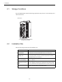
2.1 Storage Conditions - - - - - - - - - - - - - - - - - - - - - - - - - - - - - - 2-2
2.2 Installation Site - - - - - - - - - - - - - - - - - - - - - - - - - - - - - - - - 2-2
2.3 Orientation- - - - - - - - - - - - - - - - - - - - - - - - - - - - - - - - - - - - 2-3
2.4 Installation - - - - - - - - - - - - - - - - - - - - - - - - - - - - - - - - - - - - 2-4
3 Wiring
3.1 Connecting to Peripheral Devices - - - - - - - - - - - - - - - - - - - 3-2
3.1.1 Single-phase (100 V or 200 V) Main Circuit Specifications - - - - - - - 3-3
3.1.2 Three-phase (200 V) Main Circuit Specifications - - - - - - - - - - - - - - - - 3-4
3.2 SERVOPACK Internal Block Diagrams - - - - - - - - - - - - - - - - 3-5
3.3 I/O Signals- - - - - - - - - - - - - - - - - - - - - - - - - - - - - - - - - - - - 3-6
3.3.1
3.3.2
3.3.3
3.3.4
Connection Example of I/O Signal Connector (CN1) - - - - - - - - - - - - - 3-6
I/O Signals Connector (CN1)- - - - - - - - - - - - - - - - - - - - - - - - - - - - - - 3-7
I/O Signal Names and Functions - - - - - - - - - - - - - - - - - - - - - - - - - - - 3-8
Interface Circuits - - - - - - - - - - - - - - - - - - - - - - - - - - - - - - - - - - - - - - 3-9
3.4 Fully Closed Encoder Signals Connector (CN4) - - - - - - - - 3-11
3.4.1 Fully Closed Encoder Connection Example - - - - - - - - - - - - - - - - - - 3-11
3.4.2 CN4 Connector Terminal Layout - - - - - - - - - - - - - - - - - - - - - - - - - - 3-11
3.5 Connections for MECHATROLINK-II Communications - - - 3-13
3.5.1 MECHATROLINK-II Communications Connection Example- - - - - - - 3-13
3.5.2 MECHATROLINK-II Communications Connectors (CN6A, CN6B) - - 3-14
3.5.3 Precautions for Wiring MECHATROLINK-II Cables - - - - - - - - - - - - - 3-14
3.6 Examples of Combined Connections
(for Fully Closed Encoders)- - - - - - - - - - - - - - - - - - - - - - - 3-16
3.6.1 Single-phase Power Supply Specifications - - - - - - - - - - - - - - - - - - - 3-16
3.6.2 Three-phase Power Supply Specifications - - - - - - - - - - - - - - - - - - - 3-18
x
4 MECHATROLINK-II Communications
4.1 Specifications and Configuration - - - - - - - - - - - - - - - - - - - - 4-3
4.1.1 Specifications - - - - - - - - - - - - - - - - - - - - - - - - - - - - - - - - - - - - - - - - -4-3
4.1.2 System Configuration - - - - - - - - - - - - - - - - - - - - - - - - - - - - - - - - - - -4-3
4.2 Switches for MECHATROLINK-II Communications Settings - 4-4
4.2.1 Communications Settings - - - - - - - - - - - - - - - - - - - - - - - - - - - - - - - -4-4
4.2.2 Setting the Transmission Cycle - - - - - - - - - - - - - - - - - - - - - - - - - - - -4-5
4.2.3 Setting the Station Address - - - - - - - - - - - - - - - - - - - - - - - - - - - - - - -4-6
4.3 Main Commands - - - - - - - - - - - - - - - - - - - - - - - - - - - - - - - 4-7
4.3.1 No Operation (NOP: 00H) - - - - - - - - - - - - - - - - - - - - - - - - - - - - - - - -4-8
4.3.2 Read Parameter (PRM_RD: 01H) - - - - - - - - - - - - - - - - - - - - - - - - - -4-9
4.3.3 Write Parameter (PRM_WR: 02H) - - - - - - - - - - - - - - - - - - - - - - - - - 4-10
4.3.4 Read ID (ID_RD: 03H) - - - - - - - - - - - - - - - - - - - - - - - - - - - - - - - - - 4-11
4.3.5 Set Up Device (CONFIG: 04H) - - - - - - - - - - - - - - - - - - - - - - - - - - - 4-12
4.3.6 Read Alarm or Warning (ALM_RD: 05H)- - - - - - - - - - - - - - - - - - - - - 4-13
4.3.7 Clear Alarm/Warning (ALM_CLR: 06H)- - - - - - - - - - - - - - - - - - - - - - 4-14
4.3.8 Start Synchronous Communications (SYNC_SET: 0DH)- - - - - - - - - - 4-15
4.3.9 MECHATROLINK-II Connection (CONNECT: 0EH) - - - - - - - - - - - - - 4-16
4.3.10 Disconnection (DISCONNECT: 0FH) - - - - - - - - - - - - - - - - - - - - - - 4-17
4.3.11 Read Non-volatile Parameter (PPRM_RD: 1BH) - - - - - - - - - - - - - - 4-18
4.3.12 Write Non-volatile Parameter (PPRM_WR: 1CH) - - - - - - - - - - - - - - 4-19
4.3.13 Set Coordinates (POS_SET: 20H) - - - - - - - - - - - - - - - - - - - - - - - - 4-20
4.3.14 Apply Brake (BRK_ON: 21H) - - - - - - - - - - - - - - - - - - - - - - - - - - - - 4-21
4.3.15 Release Brake (BRK_OFF: 22H) - - - - - - - - - - - - - - - - - - - - - - - - - 4-22
4.3.16 Turn Sensor ON (SENS_ON: 23H): - - - - - - - - - - - - - - - - - - - - - - - 4-23
4.3.17 Turn Sensor OFF (SENS_OFF: 24H) - - - - - - - - - - - - - - - - - - - - - - 4-24
4.3.18 Stop Motion (HOLD: 25H) - - - - - - - - - - - - - - - - - - - - - - - - - - - - - - 4-25
4.3.19 Request Latch Mode (LTMOD_ON: 28H) - - - - - - - - - - - - - - - - - - - 4-26
4.3.20 Release Latch Mode (LTMOD_OFF: 29H)- - - - - - - - - - - - - - - - - - - 4-27
4.3.21 Status Monitoring (SMON: 30H) - - - - - - - - - - - - - - - - - - - - - - - - - - 4-28
4.3.22 Servo ON (SV_ON: 31H)- - - - - - - - - - - - - - - - - - - - - - - - - - - - - - - 4-29
4.3.23 Servo OFF (SV_OFF: 32H) - - - - - - - - - - - - - - - - - - - - - - - - - - - - - 4-30
4.3.24 Interpolation Feed (INTERPOLATE: 34H) - - - - - - - - - - - - - - - - - - - 4-31
4.3.25 Positioning (POSING: 35H) - - - - - - - - - - - - - - - - - - - - - - - - - - - - - 4-32
4.3.26 Constant Speed Feed (FEED: 36H) - - - - - - - - - - - - - - - - - - - - - - - 4-33
4.3.27 Interpolation Feeding with Position Detection (LATCH: 38H) - - - - - - 4-35
4.3.28 External Input Positioning (EX_POSING: 39H) - - - - - - - - - - - - - - - 4-37
4.3.29 Zero Point Return (ZRET: 3AH) - - - - - - - - - - - - - - - - - - - - - - - - - - 4-39
4.3.30 Velocity Control (VELCTRL: 3CH) - - - - - - - - - - - - - - - - - - - - - - - - 4-41
4.3.31 Torque Control (TRQCTRL: 3DH)- - - - - - - - - - - - - - - - - - - - - - - - - 4-43
4.3.32 Adjusting (ADJ: 3EH) - - - - - - - - - - - - - - - - - - - - - - - - - - - - - - - - - 4-45
4.3.33 General-purpose Servo Control (SVCTRL: 3FH) - - - - - - - - - - - - - - 4-46
4.3.34 MECHATROLINK Connection (CONNECT: 0EH) - - - - - - - - - - - - - - 4-48
4.4 Subcommands - - - - - - - - - - - - - - - - - - - - - - - - - - - - - - - - 4-49
4.4.1
4.4.2
4.4.3
4.4.4
No Operation (NOP: 00H) - - - - - - - - - - - - - - - - - - - - - - - - - - - - - - - 4-50
Read Parameter (PRM_RD:01H) - - - - - - - - - - - - - - - - - - - - - - - - - - 4-51
Write Parameter (PRM_WR:02H)- - - - - - - - - - - - - - - - - - - - - - - - - - 4-51
Read Alarm or Warning (ALM_RD:05H) - - - - - - - - - - - - - - - - - - - - - 4-52
xi
4.4.5
4.4.6
4.4.7
4.4.8
Write Non-volatile Parameter (PPRM_WR:1CH) - - - - - - - - - - - - - - Request Latch Mode (LTMOD_ON:28H) - - - - - - - - - - - - - - - - - - - Release Latch Mode (LTMOD_OFF:29H)- - - - - - - - - - - - - - - - - - - Status Monitoring (SMON:30H) - - - - - - - - - - - - - - - - - - - - - - - - - - -
4-52
4-53
4-53
4-54
4.5 Command Data Field - - - - - - - - - - - - - - - - - - - - - - - - - - - 4-55
4.5.1
4.5.2
4.5.3
4.5.4
Latch Signal Field Specifications: LT_SGN - - - - - - - - - - - - - - - - - - Option Field Specifications: OPTION - - - - - - - - - - - - - - - - - - - - - - Status Field Specifications: STATUS - - - - - - - - - - - - - - - - - - - - - - Monitor Selection and Monitor Information Field Specifications:
SEL_MON1/2/3/4, MONITOR1/2/3/4 - - - - - - - - - - - - - - - - - - - - - - 4.5.5 IO Monitor Field Specifications: IO_MON - - - - - - - - - - - - - - - - - - - 4.5.6 Substatus Field Specifications: SUBSTATUS - - - - - - - - - - - - - - - - -
4-55
4-56
4-57
4-58
4-59
4-61
4.6 Command and Response Timing - - - - - - - - - - - - - - - - - - - 4-62
4.6.1 Command Data Execution Timing - - - - - - - - - - - - - - - - - - - - - - - - - 4-62
4.6.2 Monitor Data Input Timing- - - - - - - - - - - - - - - - - - - - - - - - - - - - - - - 4-62
4.7 Operation Sequence- - - - - - - - - - - - - - - - - - - - - - - - - - - - 4-63
4.7.1 Operation Sequence for Managing Parameters Using a Controller - 4.7.2 Operation Sequence for Managing Parameters
Using SERVOPACK- - - - - - - - - - - - - - - - - - - - - - - - - - - - - - - - - - 4.7.3 Operation Sequence When Being Servo ON - - - - - - - - - - - - - - - - 4.7.4 Operation Sequence When OT (Overtravel Limit Switch)
Signal Is Input - - - - - - - - - - - - - - - - - - - - - - - - - - - - - - - - - - - - - - 4.7.5 Precaution for PSET = 1 When a Motion Command Execution is
Interrupted - - - - - - - - - - - - - - - - - - - - - - - - - - - - - - - - - - - - - - - - -
4-63
4-64
4-65
4-66
4-67
5 Trial Operation
5.1 Check Items before Trial Operation - - - - - - - - - - - - - - - - - - 5-2
5.1.1 Servomotors - - - - - - - - - - - - - - - - - - - - - - - - - - - - - - - - - - - - - - - - - 5-2
5.1.2 SERVOPACKs- - - - - - - - - - - - - - - - - - - - - - - - - - - - - - - - - - - - - - - - 5-2
5.2 Trial Operation for MECHATROLINK-II Communications - - - 5-3
5.2.1 Preparations for Trial Operation- - - - - - - - - - - - - - - - - - - - - - - - - - - - 5-3
5.2.2 Operating the Servomotor- - - - - - - - - - - - - - - - - - - - - - - - - - - - - - - - 5-4
5.3 Trial Operation Inspection - - - - - - - - - - - - - - - - - - - - - - - - - 5-5
5.4 Supplementary Information on Trial Operation - - - - - - - - - - 5-6
5.4.1 Minimum Parameters and Input Signals - - - - - - - - - - - - - - - - - - - - - 5-6
5.4.2 Servomotors with Brakes - - - - - - - - - - - - - - - - - - - - - - - - - - - - - - - - 5-7
6 Parameter Setting and Functions
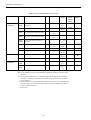
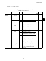
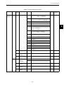
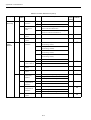
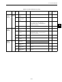
6.1 Parameter Limits and Standard Settings with
NS115 Module- - - - - - - - - - - - - - - - - - - - - - - - - - - - - - - - - 6-4
6.1.1 Parameter Limits - - - - - - - - - - - - - - - - - - - - - - - - - - - - - - - - - - - - - - 6-4
6.1.2 Standard Settings for CN1 I/O Signals - - - - - - - - - - - - - - - - - - - - - - - 6-5
6.2 Settings According to Machine Characteristics - - - - - - - - - - 6-6
6.2.1 Switching Servomotor Rotation Direction - - - - - - - - - - - - - - - - - - - - - 6-6
6.2.2 Setting the Overtravel Limit Function - - - - - - - - - - - - - - - - - - - - - - - 6-7
xii
6.2.3
6.2.4
6.2.5
6.2.6
Software Limit Settings - - - - - - - - - - - - - - - - - - - - - - - - - - - - - - - - - 6-10
Fully Closed Control - - - - - - - - - - - - - - - - - - - - - - - - - - - - - - - - - - - 6-12
Fully Closed System Specifications - - - - - - - - - - - - - - - - - - - - - - - - 6-12
Parameter Settings - - - - - - - - - - - - - - - - - - - - - - - - - - - - - - - - - - - - 6-13
6.3 Settings According to Host Controller - - - - - - - - - - - - - - - - 6-16
6.3.1
6.3.2
6.3.3
6.3.4
6.3.5
6.3.6
Sequence I/O Signals - - - - - - - - - - - - - - - - - - - - - - - - - - - - - - - - - 6-16
Electronic Gear Function - - - - - - - - - - - - - - - - - - - - - - - - - - - - - - - - 6-18
Acceleration/Deceleration Function - - - - - - - - - - - - - - - - - - - - - - - - 6-22
Positioning Function - - - - - - - - - - - - - - - - - - - - - - - - - - - - - - - - - - - 6-25
Zero Point Return - - - - - - - - - - - - - - - - - - - - - - - - - - - - - - - - - - - - - 6-26
Backlash Compensation Function - - - - - - - - - - - - - - - - - - - - - - - - - 6-27
6.4 Setting Up the SERVOPACK - - - - - - - - - - - - - - - - - - - - - - 6-29
6.4.1
6.4.2
6.4.3
6.4.4
Parameters - - - - - - - - - - - - - - - - - - - - - - - - - - - - - - - - - - - - - - - - - 6-29
Input Circuit Signal Allocation - - - - - - - - - - - - - - - - - - - - - - - - - - - - 6-29
Output Circuit Signal Allocation - - - - - - - - - - - - - - - - - - - - - - - - - - - 6-34
Monitoring - - - - - - - - - - - - - - - - - - - - - - - - - - - - - - - - - - - - - - - - - - 6-36
6.5 Setting Stop Functions - - - - - - - - - - - - - - - - - - - - - - - - - - 6-38
6.5.1 Using the Dynamic Brake - - - - - - - - - - - - - - - - - - - - - - - - - - - - - - - 6-38
6.5.2 Using the Holding Brake - - - - - - - - - - - - - - - - - - - - - - - - - - - - - - - - 6-39
6.6 Absolute Encoders - - - - - - - - - - - - - - - - - - - - - - - - - - - - - 6-43
6.6.1
6.6.2
6.6.3
6.6.4
Selecting an Absolute Encoder - - - - - - - - - - - - - - - - - - - - - - - - - - - 6-43
Absolute Encoder Setup - - - - - - - - - - - - - - - - - - - - - - - - - - - - - - - - 6-44
Multiturn Limit Setting - - - - - - - - - - - - - - - - - - - - - - - - - - - - - - - - - - 6-45
Absolute Encoder Zero Point Position Offset - - - - - - - - - - - - - - - - - - 6-47
7 Digital Operator
7.1 Connecting the Digital Operator - - - - - - - - - - - - - - - - - - - - - 7-2
7.2 Limitations in Using a Hand-held Digital Operator - - - - - - - - 7-3
7.3 Panel Operator Indicators - - - - - - - - - - - - - - - - - - - - - - - - - 7-4
8 Ratings, Specifications, and Dimensional Drawings
8.1 Ratings and Specifications - - - - - - - - - - - - - - - - - - - - - - - - 8-2
8.2 Dimensional Drawings - - - - - - - - - - - - - - - - - - - - - - - - - - - 8-3
8.2.1 NS115 Module - - - - - - - - - - - - - - - - - - - - - - - - - - - - - - - - - - - - - - - -8-3
8.2.2 SERVOPACKs - - - - - - - - - - - - - - - - - - - - - - - - - - - - - - - - - - - - - - - -8-4
9 Troubleshooting
9.1 Alarm Displays and Troubleshooting - - - - - - - - - - - - - - - - - 9-2
9.2 Troubleshooting with No Alarm Display - - - - - - - - - - - - - - 9-21
9.3 Alarm Display Table - - - - - - - - - - - - - - - - - - - - - - - - - - - - 9-23
9.4 Warning Displays - - - - - - - - - - - - - - - - - - - - - - - - - - - - - - 9-26
xiii
10 Peripheral Devices
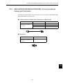
10.1 Fully Closed Encoder Connector Kit - - - - - - - - - - - - - - - - 10-2
10.2 MECHATROLINK/MECHATROLINK-II Communications
Cables and Terminator - - - - - - - - - - - - - - - - - - - - - - - - - - 10-3
Appendix A List of MECHATROLINK-II Commands and Command
Formats
A.1 MECHATROLINK-II Command List - - - - - - - - - - - - - - - - - - A-2
A.2 MECHATROLINK-II Command Format List - - - - - - - - - - - - A-5
Appendix B List of Parameters
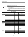
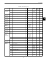
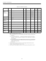
B.1 Parameters - - - - - - - - - - - - - - - - - - - - - - - - - - - - - - - - - - - B-2
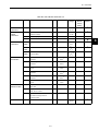
B.2 Function Switches - - - - - - - - - - - - - - - - - - - - - - - - - - - - - - B-9
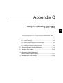
Appendix C Using the Adjusting Command (ADJ: 3EH)
C.1 Autotuning - - - - - - - - - - - - - - - - - - - - - - - - - - - - - - - - - - - C-2
C.1.1 Online Autotuning - - - - - - - - - - - - - - - - - - - - - - - - - - - - - - - - - - - - - C-3
C.1.2 Machine Rigidity Settings for Online Autotuning - - - - - - - - - - - - - - - - C-5
C.1.3 Saving Results of Online Autotuning - - - - - - - - - - - - - - - - - - - - - - - - C-7
C.1.4 Parameters Related to Online Autotuning - - - - - - - - - - - - - - - - - - - - C-9
C.2 Absolute Encoder Setup (Initialization)- - - - - - - - - - - - - - - C-11
C.3 Multiturn Limit Setting- - - - - - - - - - - - - - - - - - - - - - - - - - - C-12
C.4 Automatic Offset Adjustment of
Motor Current Detection Signals - - - - - - - - - - - - - - - - - - - C-13
C.5 Enabling the Panel Operator- - - - - - - - - - - - - - - - - - - - - - C-14
Index
Revision History
xiv
1
1
Checking Products and Part Names
This chapter describes the procedure for checking Σ-ΙΙ Series products and the
NS115 Module upon delivery. It also describes the names of product parts.
1.1 Checking Products on Delivery - - - - - - - - - - - - - - - - - - - - - 1-2
1.2 Product Part Names - - - - - - - - - - - - - - - - - - - - - - - - - - - - - 1-4
1.3 Mounting the NS115 Module - - - - - - - - - - - - - - - - - - - - - - - 1-5
1-1
1 Checking Products and Part Names
1.1
Checking Products on Delivery
The following procedure is used to check products upon delivery. Check the following items
when products are delivered.
Check Items
Comments
Are the delivered products the ones
that were ordered?
Check the model numbers marked on the nameplates
of the NS115 Module. (Refer to the descriptions of
model numbers on the following page.)
Is there any damage?
Check the overall appearance, and check for damage
or scratches that may have occurred during shipping.
Can the NS115 Module be installed on
the SERVOPACK used?
Check the model number given on the SERVOPACK
nameplate and the version seal on the front panel. The
model number must contain “SGDH” and “E” as
shown below to support the NS115 Module.
Model number (MODEL): SGDH-E-
The latter two numbers on the version seal are more
than 33.
Version seal: ∗∗∗33
If any of the above items are faulty or incorrect, contact your Yaskawa sales representative or
the dealer from whom you purchased the products.
External Appearance and Nameplate Examples
Application module model number
Application module name
SERVOPACK
NS115
MECHATROLINK
S
W
1
A
R
S
W
2
MODEL
S/N
C
N
6
A
I/F
UNIT
JUSP-NS115
VER. 000000
V81003-69
YASKAWA ELECTRIC
MADE IN JAPAN
C
N
6
B
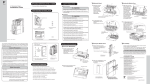
Serial number
Fig. 1.2 Nameplate Example
C
N
4
Fig. 1.1 External Appearance of
the NS115 Module
1-2
Version
1.1 Checking Products on Delivery
Model Numbers
NS115 Module
JUSP - NS11 5 - E
SERVOPACK peripheral device
Type of device:
NS11: MECHATROLINK-II interface
1-3
RoHS Compliance
Design Revision Order
1
1 Checking Products and Part Names
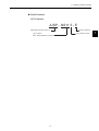
1.2
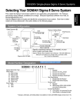
Product Part Names
The following diagram illustrates the product part names of the NS115 Module.
Ground wire: Connect to the terminal marked "G" on the SGDH SERVOPACK.
Rotary Switch (SW1): Used to set the MECHATROLINK-II station address.
NS115
S
W
1
A
LED A: Lit when an alarm occurs.
R
S
W
2
LED R: Lit when MECHATROLINK-II communications are in progress.
C
N
6
A
DIP Switch (SW2): Used to set MECHATROLINK-II communications.
Nameplate: Indicates the model and serial numbers.
C
N
6
B
MECHATROLINK-II Communications CN6A and CN6B Connectors:
Connects to the MECHATROLINK-II system.
C
N
4
CN4 Fully Closed Encoder Signal Connector: Used for fully closed signal connection.
Fig. 1.3 NS115 Module
1-4
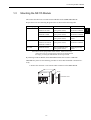
1.3 Mounting the NS115 Module
1.3
Mounting the NS115 Module
This section describes how to mount an NS115 Module on the SGDH SERVOPACK.
Prepare the screws for connecting the ground wire as shown in the following table:
Mounting Type
SERVOPACK Models
Screw
Remarks
SGDH-A3 to 02BE
SGDH-A3 to 10AE
M3 × 10 round-head screw
(spring or flat washer)
Use attached screws
on the NS115 Module.
SGDH-15 to 50AE
SGDH-05 to 30DE
M4 × 10 round-head screws
(spring or flat washer)
Use attached screws
on the NS115 Module.
SGDH-60/75AE
M4 × 8 round-head screw
(spring or flat washer)
Use front panel fixer
screws.
Rack Mounted
SGDH-A3 to 02BE-R
SGDH-A3 to 50AE-R
SGDH-05 to 30DE-R
M4 × 6 round-head screws
(spring or flat washer)
Use attached screws
on the NS115 Module.
Duct Vent
SGDH-60/75AE-P
M4 × 8 round-head screw
(spring or flat washer)
Use front panel fixer
screws.
Base Mounted
Note: Be sure to use spring washers or flat washers. Failure to do so may
result in the screws for connecting the ground wire protruding behind
the flange, preventing the SERVOPACK from being mounted.
By mounting an NS115 Module, the SGDH SERVOPACK can be used in a MECHATROLINK-II system. Use the following procedure to ensure NS115 Module is mounted correctly.
1. Remove the connector cover from the CN10 connector on the SERVOPACK.
CN10
YASKAWA SERVOPACK
SGDH
Connector cover
MODE/SET
CHARGE
DATA /
POWER
1-5
1
1 Checking Products and Part Names
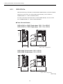
2. Mount the NS115 Module on the SERVOPACK.
Connector (Connect to SERVOPACK)
SERVOPACK connector CN10
YASKAWA
SERVOPACK
SGDH-
NS115
S
W
1
A
R
S
W
2
C
N
6
A
C
N
6
B
C
N
4
3. For grounding, connect a ground wire of the NS115 Module to the point marked “G” on
the SERVOPACK.
Ground wire
"G"
YASKAWA SERVOPACK
SGDH -
MODE/SET
NS115
DATA/
CHARGE
POWER
For SERVOPACK (30 W to 5.0 kW)
"G"
Ground wire
YASKAWA
SERVOPACK 200V
SGDH
NS100
For SERVOPACK (6.0 kW to 7.5 kW)
1-6
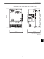
1.3 Mounting the NS115 Module
When the NS115 Module has been mounted correctly, the SERVOPACK will appear as
shown in the following diagram.
YASKAWA SERVOPACK
SGDH
200V
NS115
S
W
1
A
R
S
W
2
C
N
6
A
C
N
6
B
C
N
4
1-7
1
2
Installation
This chapter describes precautions for Σ-ΙΙ Series product installation.
The SGDH SERVOPACKs are base-mounted servo controller. Incorrect installation will cause problems. Always observe the installation precautions shown
in this chapter.
2.1 Storage Conditions - - - - - - - - - - - - - - - - - - - - - - - - - - - - - - 2-2
2.2 Installation Site - - - - - - - - - - - - - - - - - - - - - - - - - - - - - - - - 2-2
2.3 Orientation - - - - - - - - - - - - - - - - - - - - - - - - - - - - - - - - - - - - 2-3
2.4 Installation - - - - - - - - - - - - - - - - - - - - - - - - - - - - - - - - - - - - 2-4
2-1
2
2 Installation
2.1
Storage Conditions
Store the SERVOPACK within the following temperature range when it is stored with the power
cable disconnected.
-20 to 85°C
YASKAWA SERVOPACK
SGDH
200V
NS115
S
W
1
A
R
S
W
2
C
N
6
A
C
N
6
B
C
N
4
Σ-II Series SGDH SERVOPACK
with NS115 mounted
2.2
Installation Site
Take the following precautions at the installation site.
Situation
Installation Precaution
Installation in a
Control Panel
Design the control panel size, unit layout, and cooling method so that
the temperature around the SERVOPACK does not exceed 55°C.
Installation Near a
Heating Unit
Minimize heat radiated from the heating unit as well as any temperature
rise caused by natural convection so that the temperature around the
SERVOPACK does not exceed 55°C.
Installation Near a
Source of Vibration
Install a vibration isolator beneath the SERVOPACK to avoid subjecting it to vibration.
Installation at a Site
Exposed to Corrosive
Gas
Corrosive gas does not have an immediate effect on the SERVOPACK,
but will eventually cause electronic components and contactor-related
devices to malfunction. Take appropriate action to avoid corrosive gas.
Other Situations
Do not install the SERVOPACK in hot or humid locations, or locations
subject to excessive dust or iron powder in the air.
2-2
2.3 Orientation
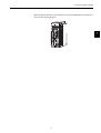
2.3
Orientation
Install the SERVOPACK perpendicular to the wall as shown in the figure. The SERVOPACK
must be oriented this way because it is designed to be cooled by natural convection or cooling
fan.
Secure the SERVOPACK using 2 to 4 mounting holes. The number of holes depends on the
SERVOPACK capacity.
2
Wall
MADE IN JAPAN
Ventilation
2-3
2 Installation
2.4
Installation
Follow the procedure below to install multiple SERVOPACKs side by side in a control panel.
Cooling fan
Cooling fan
50 mm (1.97in) min.
30 mm (1.18in) min.
10 mm (0.39in) min.
50 mm (1.97in) min.
SERVOPACK Orientation
Install the SERVOPACK perpendicular to the wall so that the front panel (containing connectors) faces outward.
Cooling
As shown in the figure above, provide sufficient space around each SERVOPACK for cooling by cooling fans or natural convection.
Side-by-side Installation
When installing SERVOPACKs side by side as shown in the figure above, provide at least
10 mm (0.39 in) between and at least 50 mm (1.97 in) above and below each SERVOPACK.
Install cooling fans above the SERVOPACKs to avoid excessive temperature rise and to
maintain even temperature inside the control panel.
Environmental Conditions in the Control Panel
• Ambient Temperature:0 to 55°C
• Humidity: 90% RH or less
• Vibration: 4.9 m/s2
• Condensation and Freezing:None
• Ambient Temperature for Long-term Reliability: 45°C max.
2-4
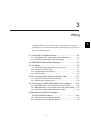
3
Wiring
This chapter describes the procedure used to connect Σ-ΙΙ Series products to
peripheral devices when an NS115 Module is mounted and gives typical examples of I/O signal connections.
3.1 Connecting to Peripheral Devices - - - - - - - - - - - - - - - - - - - 3-2
3.1.1 Single-phase (100 V or 200 V) Main Circuit Specifications - - - - - - - - 3-3
3.1.2 Three-phase (200 V) Main Circuit Specifications - - - - - - - - - - - - - - - 3-4
3.2 SERVOPACK Internal Block Diagrams - - - - - - - - - - - - - - - - 3-5
3.3 I/O Signals - - - - - - - - - - - - - - - - - - - - - - - - - - - - - - - - - - - - 3-6
3.3.1
3.3.2
3.3.3
3.3.4
Connection Example of I/O Signal Connector (CN1) - - - - - - - - - - - I/O Signals Connector (CN1) - - - - - - - - - - - - - - - - - - - - - - - - - - - - I/O Signal Names and Functions - - - - - - - - - - - - - - - - - - - - - - - - - Interface Circuits - - - - - - - - - - - - - - - - - - - - - - - - - - - - - - - - - - - - - -
3-6
3-7
3-8
3-9
3.4 Fully Closed Encoder Signals Connector (CN4) - - - - - - - - 3-11
3.4.1 Fully Closed Encoder Connection Example - - - - - - - - - - - - - - - - - - 3-11
3.4.2 CN4 Connector Terminal Layout - - - - - - - - - - - - - - - - - - - - - - - - - - 3-11
3.5 Connections for MECHATROLINK-II Communications - - - 3-13
3.5.1 MECHATROLINK-II Communications Connection Example - - - - - - 3-13
3.5.2 MECHATROLINK-II Communications Connectors (CN6A, CN6B) - - 3-14
3.5.3 Precautions for Wiring MECHATROLINK-II Cables - - - - - - - - - - - - 3-14
3.6 Examples of Combined Connections
(for Fully Closed Encoders) - - - - - - - - - - - - - - - - - - - - - - - 3-16
3.6.1 Single-phase Power Supply Specifications - - - - - - - - - - - - - - - - - - 3-16
3.6.2 Three-phase Power Supply Specifications - - - - - - - - - - - - - - - - - - - 3-18
3-1
3
3 Wiring
3.1
Connecting to Peripheral Devices
This section provides examples of standard Σ-ΙΙ Series product connections to peripheral
devices.
It also briefly explains how to connect each peripheral device.
3-2
3.1 Connecting to Peripheral Devices
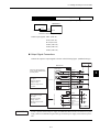
Single-phase (100 V or 200 V) Main Circuit Specifications
Host
Controller
Molded-case Circuit
Breaker (MCCB)
Controller for MECHATROLINK-II
Power supply
Single-phase 200 VAC
R S T
218IF-01
MP2300
YASKAWA
RDY
RUN RUN
ALM
TX
ERR STRX
BAT
STOP
SUP
INT
CNFG
MON
TEST
Protects the power line by shutting
the circuit OFF
when overcurrent
is detected.
ERR
COL
TX
RX
INIT
TEST
OFF
ON
SW1
OFF ON
PORT
M-I/II
BATTERY
Option
Option
3.1.1
CPU I/O
DC24V
10Base-T
DC 0V
Molded-case
circuit breaker
Noise Filter
Digital Operator (see note.)
Used to eliminate external noise
from the power line.
JUSP-OP02A-2
Allows the user to set
parameters or operation references and to
display operation or
alarm status.
Communication is also
possible with a personal computer.
Noise filter
Note Used for maintenance. Be sure to coordinate operation from these devices with controls exerted by the host controller.
Magnetic Contactor
HI Series
Turns the servo
ON and OFF.
Install a surge
suppressor on the
magnetic contactor.
Magnetic
contactor
Power Supply for Brake
Used for a servomotor with a
brake.
Brake
power
supply
Magnetic
contactor
Power
supply
ground
line
L1 L2
U V W
L1C L2C
B1 B2
Regenerative
resistor
(optional)
Regenerative Resistor
Connect an external regenerative
resistor to terminals B1and B2 if
the regenerative capacity is
insufficient.
3-3
Encoder
Cable
Encoder
Connector
3
3 Wiring
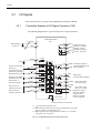
3.1.2 Three-phase (200 V) Main Circuit Specifications
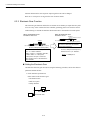
Three-phase (200 V) Main Circuit Specifications
Host
Controller
Power supply
Single-phase 200 VAC
Molded-case Circuit
Breaker (MCCB)
R S T
Controller for MECHATROLINK-II
218IF-01
MP2300
YASKAWA
Protects the power line by shutting
the circuit OFF
when overcurrent
is detected.
RDY
RUN RUN
ALM
TX
ERR STRX
BAT
STOP
SUP
INT
CNFG
MON
TEST
ERR
COL
TX
RX
INIT
TEST
SW1
OFF ON
OFF
ON
PORT
M-I/II
BATTERY
Option
Option
3.1.2
CPU I/O
DC24V
10Base-T
DC 0V
Molded-case
circuit breaker
Noise Filter
Used to eliminate external noise
from the power line.
Digital Operator (see note.)
JUSP-OP02A-2
Allows the user to set
parameters or operation references and to
display operation or
alarmstatus.
Communication is also
possible with a personal computer.
Noise filter
Magnetic Contactor
HI Series
Turns the servo
ON and OFF.
Install a surge
suppressor on the
magnetic contactor.
Note Used for maintenance. Be sure to coordinate operation from these devices with controls
exerted by the host controller.
Magnetic
contactor
U V W
Power
supply
ground
line
Power Supply for Brake
Used for a servomotor with a
brake.
Magnetic
contactor
Brake
power
supply
L1 L2 L3L1C L2C
Encoder
Cable
Encoder
Connector
B1 B2
Regenerative
resistor
(optional)
Regenerative Resistor
If the capacity of the internal regenerative resistor is
insufficient, remove the wire between B2 and B3 and
connect an external regenerative resistor to terminals B1 and B2.
For SERVOPACKs with a capacity of 6.0 kW or higher, connect an external regenerative resistor between terminals B1 and B2.
(There is no terminal B3 on these SEERVOPACKs.)
3-4
3.2 SERVOPACK Internal Block Diagrams
3.2
SERVOPACK Internal Block Diagrams
The following sections show an internal block diagram for the SERVOPACK with an NS115
Module.
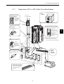
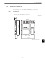
30 to 400 W 200-V and 30 to 200 W 100-V Models
Single-phase
+10%
200 to 230 V -15%
(50/60Hz)
B1
THS1
RY1
2
D2D3D4
PM1 - 1
P1
Noise filter
FU1
1MC
B2
1
L1
U
U
C1
V
V
T
L2
AC servomotor
R7
D1
CHARGE
R
PM1 - 2
P2
W
TR1
R8
3
W
N2
N1
Relay
drive
Voltage
Sensor
Gate drive
Voltage
Sensor
Gate drive overcurrent protector
CN2
PG
Interface
L1C
L2C
Current
Sensor
±5V
+15V
DC/DC
converter
For battery
connection
CN8
ASIC
(PWM control)
+5V
±12V
CN1
+5V
Power
OFF
Power
ON
0V
1MC
POWER
Monitor display
1MC
(5Ry)
Surge
suppressor
CPU
(position and speed
calculations)
Analog voltage
converter
I/O
CN5
Open during servo
alarm
CN3
Analog monitor
output for
supervision
Sequence I/O
CN10
Digital Operator/
personal computer
CN10
CN6A
Other station
BUS interface
CN6B
Other station
MECHATROLINK-II
Communications interface
CN4
CPU
(position commands,
command interpretation,
arithmetic processing,
etc.)
+5 V
Power
supply
R
SW1
Station No.
SW2
+5 V
3-5
Baud rate
A
Fully closed PG
3 Wiring
3.3.1 Connection Example of I/O Signal Connector (CN1)
3.3
I/O Signals
This section describes I/O signals for the SERVOPACK with NS115 Module.
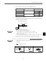
3.3.1
Connection Example of I/O Signal Connector (CN1)
The following diagram shows a typical example of I/O signal connections.
SGDH SERVOPACK
*1
BAT +
21
BAT -
22
CN1
37
ALO1
38
ALO2
39
1
ALO3
SG
40
25
/COIN+ Positioning completed
/DEC
41
26
/COIN - been completed)
Forward run prohibited
(Prohibited when OFF)
P OT
42
27
/BK+
Reverse run prohibited
(Prohibited when OFF)
N OT
43
28
/BK -
External latch 1*3
(Latched when ON)
/EXT1
44
29
/S - RDY+
External latch 2 *3
(Latched when ON)
/EXT2
45
30
/S - RDY-
31
ALM+
External latch 3 *3
(Latched when ON)
/EXT3
32
ALM - Photocoupler output
Backup battery +
2.8 to 4.5 V *2 -
+24VIN
+24V
+
-
Zero point return deceleration LS *3
(LS enabled when ON)
47
Alarm code output
Maximum operating
voltage: 30 VDC
Maximum operating
current: 20 mA DC
3.3kΩ
46
(ON when positioning has
Connector shell
Brake output
(ON when brake released)
Servo ready output
(ON when ready)
Servo alarm output
(OFF for an alarm)
Maximum operating
voltage: 30 VDC
Maximum operating
current: 50 mA DC
FG
Connect shield to connector shell.
* 1.
P represents twisted-pair wires.
* 2. When using an absolute encoder, connect a backup battery only when
there is no battery connected to the CN8.
* 3. Make signal allocations using parameters. (Refer to 6.1.2 Standard
Settings for CN1 I/O Signals.)
Fig. 3.1 I/O Signal Connections for CN1 Connectors
3-6
3.3 I/O Signals
3.3.2
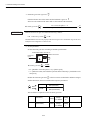
I/O Signals Connector (CN1)
The following diagram shows the layout of CN1 terminals.
CN1 Terminal Layout
1
2
SG
SG
27
GND
3
4
-
-
29
8
SG
-
10
SG
GND
12
-
-
-
31
7
-
-
9
-
-
11
-
-
13
-
-
-
-
20
-
22
BAT (-)
-
-
-
37
ALO1
Alarm code
output
45
BAT (+)
47
-
49
/COIN +
/DEC *
N-OT
/EXT2 *
+24VIN
-
25
ALO3
Battery (+)
Battery (-)
23
24
35
-
21
Servo alarm
output
-
43
-
ALM+
-
19
Servo ready
output
-
41
-
/SRDY+
-
17
18
-
Brake interlock output
33
39
15
16
-
GND
-
14
-
/BK+ *
-
5
6
GND
-
(open-collector output)
Zero point
return deceleration LS
input
Reverse run
prohibited
input
External latch
signal 2 input
External
power supply
input
26
/COIN-
Positioning
complete
output
28
/BK- *
Brake interlock output
30
/S-RDY-
Servo ready
output
32
ALM-
Servo alarm
output
34
-
-
36
-
-
38
ALO2
Alarm code
output
40
-
-
42
P-OT
Forward drive
prohibited
input
44
/EXT1 *
External latch
signal 1 input
46
/EXT3 *
External latch
signal 3 input
48
-
-
50
-
-
-
Positioning
complete
output
* Make signal allocations using parameters. (Refer to 6.1.2 Standard Settings for CN1 I/O Signals.)
Note: 1. Do not use unused terminals for relays.
2. Connect the shield of the I/O signal cable to the connector shell.
The shield is connected to the FG (frame ground) at the SERVOPACK-end connector.
CN1 Specifications
Specifications for
SERVOPACK
Connectors
10250-52A2JL 50-p
Right Angle Plug
Applicable Receptacles
Soldered
10150-3000VE
3-7
Case
10350-52A0-008
Manufacturer
Manufactured by
Sumitomo 3M Ltd.
3
3 Wiring
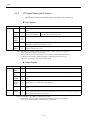
3.3.3 I/O Signal Names and Functions
3.3.3
I/O Signal Names and Functions
The following section describes SERVOPACK I/O signal names and functions.
Input Signals
Signal Name
Common
Pin No.
Function
/DEC
41
Zero point return deceleration limit switch: Deceleration LS used when the motor returns to the zero
point.
P-OT
N-OT
42
43
Forward run prohibited
Reverse run prohibited
/EXT1
/EXT2
/EXT3
44
45
46
External latch signals 1, 2, and 3: External signals for latching the current FB pulse counter.
+24VIN
47
Control power supply input for sequence signals: Users must provide the +24-V power supply.
Allowable voltage fluctuation range: 11 to 25 V
BAT (+)
BAT (-)
21
22
Connecting pin for the absolute encoder backup battery.
Connect to either CN8 or CN1.
Overtravel prohibited: Stops servomotor when movable part travels
beyond the allowable range of motion.
Note: 1. The functions allocated to /DEC, P-OT, N-OT, /EXT1, /EXT2, /EXT3, P-CL, and N-CL
input signals can be changed via parameters.
2. The forward/reverse run prohibited function uses software to stop the SERVOPACK. This
method may not satisfy the standards depending on the safety specifications for the
application. If necessary, add an external safety circuit.
Output Signals
Signal Name
Common
Position
Pin No.
Function
ALM+
ALM-
31
32
Servo alarm: Turns OFF when an error is detected.
/BK+
/BK-
27
28
Brake interlock: Output that controls the brake. The brake is released when this signal is ON.
/S-RDY+
/S-RDY-
29
30
Servo ready: ON if there is no servo alarm when the control/main circuit power supply is turned
ON.
ALO1
ALO2
ALO3
37
38
39 (1)
Alarm code output: Outputs 3-bit alarm codes.
Open-collector: 30 V and 20 mA rating maximum
FG
Shell
Connected to frame ground if the shield wire of the I/O signal cable is connected to the connector
shell.
25
26
Positioning completed (output in Position Control Mode): Turns ON when the number of error
pulses reaches the value set. The setting is the number of error pulses set in reference units (input
pulse units defined by the electronic gear).
/COIN+
/COIN-
Note: 1. Pin numbers in parenthesis () indicate signal grounds.
2. The functions allocated to /BK, /S-RDY, and /COIN output signals can be changed to
/CLT, /VCT, /TGON, /WARN, or /NEAR signals via parameters.
3-8
3.3 I/O Signals
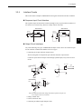
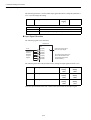
3.3.4
Interface Circuits
This section shows examples of SERVOPACK I/O signal connection to the host controller.
Sequence Input Circuit Interface
The sequence input circuit interface connects through a relay or open-collector transistor circuit. Select a low-current relay, otherwise a faulty contact will result.
SERVOPACK
SERVOPACK
24 VDC
50 mA min.
24 VDC
50 mA min.
+24 VIN 3.3 k
/DEC, etc.
+24 VIN
3.3 k
/DEC, etc.
3
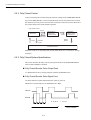
Output Circuit Interfaces
Any of the following two types of SERVOPACK output circuits can be used. Form an input
circuit at the host controller that matches one of two types.
• Connecting to an Open-collector Output Circuit
Alarm code signals are output from open-collector transistor output circuits.
Connect an open-collector output circuit through a photocoupler, relay or line receiver
circuit.
5 to 12 VDC
Photocoupler
5 to 12 VDC
SERVOPACK
end
0V
0V
0V
0V
5 to 12 VDC
SERVOPACK
end
0V
0V
Note: The maximum allowable voltage and current capacities for open-collector output circuits are as follows:
• Voltage: 30VDC max.
• Current: 20 mA DC max.
• Connecting to a Photocoupler Output Circuit
3-9
Relay
3 Wiring
3.3.4 Interface Circuits
Photocoupler output circuits are used for servo alarm, servo ready, and other sequence
output signal circuits.
Connect a photocoupler output circuit through a relay or line receiver circuit.
5 to 24 VDC
0V
Relay
5 to 12 VDC
SERVOPACK end
SERVOPACK end
0V
0V
Note: The maximum allowable voltage and current capacities for photocoupler output circuits are as follows:
• Voltage: 30 VDC max.
• Current: 50 mA DC max.
3-10
0V
3.4 Fully Closed Encoder Signals Connector (CN4)
3.4
Fully Closed Encoder Signals Connector (CN4)
This section describes the wiring for the fully closed encoder signals connector (CN4).
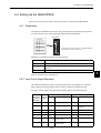
3.4.1
Fully Closed Encoder Connection Example
The following diagram shows an example of CN4 connections.
NS115
CN4
1,2,3
16
17
18
19
14
15
GND
A
/A
B
/B
Z
/Z
PG0V
FA
/FA
FB
/FB
FC
/FC
External PG
3
External
power supply
Note:
3.4.2
represents twisted-pair wires.
CN4 Connector Terminal Layout
The following diagram shows the CN4 connector terminal layout and connector specifications.
CN4 Connector Terminal Layout
1
2
4
PG0 V
-
Signal
ground
3
-
-
-
-
16
-
FA
18
-
FC
-
-
-
-
FB
20
-
Note: 1. The connector shell is connected to the FG (frame ground).
2. Do not use unused terminals as relay terminals.
3-11
11
-
-
13
-
-
15
/FC
Phase-C
input
17
/FA
Phase-A
input
19
/FB
Phase-B
input
-
PG0 V
-
9
10
12
14
7
8
Signal
ground
5
6
PG0 V
Phase-C
input
Phase-A
input
Phase-B
input
-
3 Wiring
3.4.2 CN4 Connector Terminal Layout
CN4 Specifications
Specifications for
SERVOPACK
Connectors
10220-52A2JL
20-pin Right Angle Plug
Applicable Receptacles
Soldered
10120-3000VE
3-12
Case
10320-52A0-008
Manufacturer
SUMITOMO 3M
LTD.
3.5 Connections for MECHATROLINK-II Communications
Connections for MECHATROLINK-II Communications
This section describes the connection and wiring of connectors for MECHATROLINK-II communications.
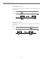
3.5.1
MECHATROLINK-II Communications Connection Example
The following diagram shows an example of connections between a host controller and a
SERVOPACK using MECHATROLINK-II communications cables (CN6A, CN6B).
Host controller
218IF-01
MP2300
YASKAWA
RDY
RUN
RUN
ERR
ALM
TX
ERR
BAT
STRX
COL
STOP
SUP
INT
CNFG
MON
TEST
TX
RX
INIT
TEST
OFF
ON
SW1
OFF ON
PORT
3
BATTERY
CPU I/O
DC24V
10Base-T
Option
M-I/II
Option
3.5
L1
L2
Ln
DC 0V
Terminator
Note: 1. The length of the cable between stations (L1, L2, ... Ln) must be
0.5 m or more.
2. L1 + L2 ... + Ln must be 50 m or less.
3-13
3 Wiring
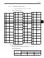
3.5.2 MECHATROLINK-II Communications Connectors (CN6A, CN6B)
3.5.2
MECHATROLINK-II Communications Connectors (CN6A, CN6B)
The terminal layout and specifications of the CN6A and CN6B connectors are shown below.
CN6A and CN6B Connectors Terminal Layout
1
2
3
4
-
/S
S
SH
Not connected
Serial data I/O
Not connected
Note: The connector shell is connected to the FG (frame ground).
CN6A and CN6B Specifications
Specifications for SERVOPACK Connectors
DUSB-ARA41-T11
3.5.3
Applicable Plug (or Socket)
Connector (on Cable)
DUSB-APA41-B1-C50
Manufacturer
DDK Ltd.
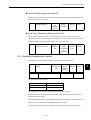
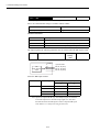
Precautions for Wiring MECHATROLINK-II Cables
Observe the following precautions when wiring MECHATROLINK-II cables.
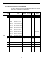
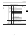
Number of Connectable Stations
The number of connectable stations is determined by the settings for the transmission cycle
and number of transmission bytes. When the communications retry channel is 1, the number
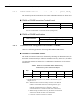
of connectable stations is as follows for the combinations of transmission cycle and transmission bytes.
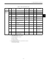
Table 3.1 Number of Connectable Stations Determined by
Transmission Cycle and Transmission Bytes
Transmission
Bytes
Transmission Cycle
0.5
ms∗
1.0 ms
2.0 ms
3.0 ms
4.0 ms
17
6
14
30
30
30
30
3
8
20
30
30
* When the transmission cycle is 0.5 ms, set the communications cycle in
multiples of 1.0 ms.
Note: 1. When the number of stations actually connected is less than the
number of connectable stations, the remaining channels, up to 7,
can be used as communications retry channels.
(Number of communications retry channels = Number of
connnectable stations - Number of actual stations connected+1)
2. When not using communications retry, the number of connnectable
stations is the number in Table 3.1 increased by one.
3. Connect a repeater for more than 16 stations.
3-14
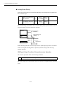
3.5 Connections for MECHATROLINK-II Communications
Cables
Be sure to use the specified cables.
For more information on cables, refer to 10.2 MECHATROLINK/MECHATROLINK-II
Communications Cables and Terminator.
Cable Length
The total cable length must be 50 m or less.
Cable Length for Stations
The length of the cable between stations must be 0.5 m or more.
Terminal Processing
Install a Terminator on the last SERVOPACK and host controller.
For more information on Terminators, refer to 10.2 MECHATROLINK/MECHATROLINKII Communications Cables and Terminator.
3-15
3
3 Wiring
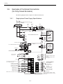
3.6.1 Single-phase Power Supply Specifications
3.6
Examples of Combined Connections
(for Fully Closed Encoders)
The following diagrams show examples of combined connections.
3.6.1
Single-phase Power Supply Specifications
+10%
Single-phase 200 to 230 VAC -15%
(50/60Hz)
Power
ON
Power
OFF
Noise filter
Alarm
processing
1MC
Be sure to attach a surge suppressor to the
excitation coil of the magnetic contactor and relay.
1MC
B1
L1
L2
B2
B3
A 1
B 2
C 3
U
V
W
SGDH-E SERVOPACK
Speed and position
detector
PG
CN2
+ 1
2
G
∗4
Connect to ground.
Connect a Terminator (JEPMC-W6022)
of the end connector of the last SERVOPACK.
Backup battery
2.8 to 4.5V *2
∗1
+
Be sure to prepare the end
of shield properly.
Fully closed speed
and position detector
NS115
PG
CN4
2
3
4
CN6B
BAT +
21
BAT
22
+24 VIN
47
+24 V
Zero point return deceleration LS *3
(LS enabled when ON)
CN6A
3
4
/S
S
SH
Terminator
+
2
/S
S
SH
To next MECHATROLINK-II slave
Fully closed PG
power supply
CN1
3.3kΩ
40
/DEC
M
D 4
L1C
L2C
Servomotor
37
ALO1
38
ALO2
39
ALO3
1
SG
25
/COIN+
26
27
/COIN
/BK+
41
Forward run prohibited
(Prohibited when OFF)
P OT
Reverse run prohibited
(Prohibited when OFF)
N OT
43
28
29
/BK
External latch 1 *3
(Latched when ON)
/EXT1
44
30
/S-RDY
External latch 2 *3
(Latched when ON)
/EXT2
45
External latch 3 *3 (Latched when ON)
/EXT3
46
42
/S-RDY+
31
ALM+
32
ALM
Connector shell
Alarm code output
Maximum operating voltage:
30 VDC
Maximum operating current:
20 mA DC
Positioning completed
(ON when positioning has
been completed)
Brake output *3
(ON when brake is
released)
Servo ready output
(ON when ready)
Servo alarm output
(OFF for an alarm)
Photocoupler Outputs
Maximum operating voltage: 30 VDC
Maximum operating current: 50 mA DC
FG Connect shield to connector shell.
3-16
3.6 Examples of Combined Connections (for Fully Closed Encoders)
* 1.
represents twisted-pair wires.
* 2. When using an absolute encoder, connect a backup battery only when there is no battery connected to the CN8.
* 3. Make signal allocations using parameters.(Refer to 6.1.2 Standard Settings for CN1 I/O Signals.)
* 4. Connect the ground wire of the NS115 Module to the marked “G” on the SERVOPACK.
(Refer to 1.3 Mounting the NS115 Module.)
3
3-17
3 Wiring
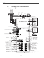
3.6.2 Three-phase Power Supply Specifications
3.6.2
Three-phase Power Supply Specifications
+10%
Three-phase 200 to 230 VAC -15%
50/60Hz
Power
ON
Power
OFF
Noise filter
Alarm
processing
1MC
Be sure to attach a surge suppressor to the
excitation coil of the magnetic contactor and relay.
1MC
B1
L1
B2
B3
L2
L3
L1C
A 1
B 2
C 3
U
V
W
Speed and position
detector
PG
CN2
+ 1
2
G
∗5
Connect to ground.
To next MECHATROLINK-II slave
Terminator
Connect a Terminator (JEPMC-W6022)
of the end connector of the last SERVOPACK.
Backup battery
2.8 to 4.5V *2
+
+
/S
S
SH
2
/S
S
SH
2
CN6A
PG
CN4
3
4
CN6B
BAT +
21
BAT
22
+24 VIN
47
+24 V
Be sure to prepare the end
of shield properly.
Fully closed speed
and position detector
NS115
3
4
M
D 4
SGDH-E SERVOPACK *3
L2C
Servomotor
Fully closed PG
power supply
CN1
3.3kΩ
40
37
ALO1
38
ALO2
39
ALO3
1
SG
Alarm code output
Maximum operating
voltage: 30 VDC
Maximum operating
current: 20 mA DC
Zero point return deceleration LS *4
(LS enabled when ON)
/DEC
25
/COIN+ Positioning completed
Forward run prohibited
(Prohibited when OFF)
P OT
42
26
27
/COIN
/BK+
Reverse run prohibited
(Prohibited when OFF)
N OT
43
28
29
/BK
External latch 1 *4
(Latched when ON)
/EXT1
44
30
External latch 2 *4
(Latched when ON)
/EXT2
45
External latch 3 *4
(Latched when ON)
/EXT3
46
41
FG
3-18
Brake output *4
(ON when brake is
/S-RDY+ released)
Servo ready output
/S-RDY (ON when ready)
31
ALM+
32
ALM
Connector shell
(ON when positioning has
been completed)
Servo alarm output
(OFF for an alarm)
Photocoupler Outputs
Maximum operating voltage: 30 VDC
Maximum operating current: 50 mA DC
Connect shield to connector shell.
3.6 Examples of Combined Connections (for Fully Closed Encoders)
* 1.
represents twisted-pair wires.
* 2. When using an absolute encoder, connect a backup battery only when there is no battery connected to the CN8.
* 3. Connect an external regenerative resistor between terminals B1 and B2 for SERVOPACKs
with a capacity of 6.0 kW or higher.
* 4. Make signal allocations using parameters.(Refer to 6.1.2 Standard Settings for CN1 I/O Signals.)
* 5. Connect the ground wire of the NS115 Module to the marked “G” on the SERVOPACK.(Refer to 1.3 Mounting the NS115 Module.)
3
3-19
4
MECHATROLINK-II Communications
This chapter describes MECHATROLINK-II communications specifications,
commands, and power ON sequence.
4.1 Specifications and Configuration - - - - - - - - - - - - - - - - - - - - 4-3
4.1.1 Specifications - - - - - - - - - - - - - - - - - - - - - - - - - - - - - - - - - - - - - - - - 4-3
4.1.2 System Configuration - - - - - - - - - - - - - - - - - - - - - - - - - - - - - - - - - - 4-3
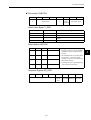
4.2 Switches for MECHATROLINK-II Communications Settings - 4-4
4.2.1 Communications Settings - - - - - - - - - - - - - - - - - - - - - - - - - - - - - - - 4-4
4.2.2 Setting the Transmission Cycle - - - - - - - - - - - - - - - - - - - - - - - - - - - 4-5
4.2.3 Setting the Station Address - - - - - - - - - - - - - - - - - - - - - - - - - - - - - - 4-6
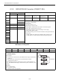
4.3 Main Commands - - - - - - - - - - - - - - - - - - - - - - - - - - - - - - - 4-7
4.3.1 No Operation (NOP: 00H) - - - - - - - - - - - - - - - - - - - - - - - - - - - - - - - 4-8
4.3.2 Read Parameter (PRM_RD: 01H) - - - - - - - - - - - - - - - - - - - - - - - - - 4-9
4.3.3 Write Parameter (PRM_WR: 02H) - - - - - - - - - - - - - - - - - - - - - - - - 4-10
4.3.4 Read ID (ID_RD: 03H) - - - - - - - - - - - - - - - - - - - - - - - - - - - - - - - - 4-11
4.3.5 Set Up Device (CONFIG: 04H) - - - - - - - - - - - - - - - - - - - - - - - - - - - 4-12
4.3.6 Read Alarm or Warning (ALM_RD: 05H) - - - - - - - - - - - - - - - - - - - - 4-13
4.3.7 Clear Alarm/Warning (ALM_CLR: 06H) - - - - - - - - - - - - - - - - - - - - - 4-14
4.3.8 Start Synchronous Communications (SYNC_SET: 0DH) - - - - - - - - - 4-15
4.3.9 MECHATROLINK-II Connection (CONNECT: 0EH) - - - - - - - - - - - - 4-16
4.3.10 Disconnection (DISCONNECT: 0FH) - - - - - - - - - - - - - - - - - - - - - 4-17
4.3.11 Read Non-volatile Parameter (PPRM_RD: 1BH) - - - - - - - - - - - - - 4-18
4.3.12 Write Non-volatile Parameter (PPRM_WR: 1CH) - - - - - - - - - - - - - 4-19
4.3.13 Set Coordinates (POS_SET: 20H) - - - - - - - - - - - - - - - - - - - - - - - 4-20
4.3.14 Apply Brake (BRK_ON: 21H) - - - - - - - - - - - - - - - - - - - - - - - - - - - 4-21
4.3.15 Release Brake (BRK_OFF: 22H) - - - - - - - - - - - - - - - - - - - - - - - - 4-22
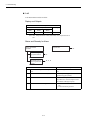
4.3.16 Turn Sensor ON (SENS_ON: 23H): - - - - - - - - - - - - - - - - - - - - - - 4-23
4.3.17 Turn Sensor OFF (SENS_OFF: 24H) - - - - - - - - - - - - - - - - - - - - - 4-24
4.3.18 Stop Motion (HOLD: 25H) - - - - - - - - - - - - - - - - - - - - - - - - - - - - - 4-25
4.3.19 Request Latch Mode (LTMOD_ON: 28H) - - - - - - - - - - - - - - - - - - 4-26
4.3.20 Release Latch Mode (LTMOD_OFF: 29H) - - - - - - - - - - - - - - - - - - 4-27
4.3.21 Status Monitoring (SMON: 30H) - - - - - - - - - - - - - - - - - - - - - - - - - 4-28
4-1
4
4 MECHATROLINK-II Communications
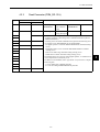
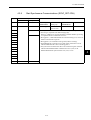
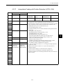
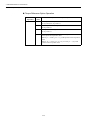
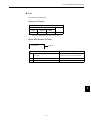
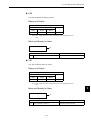
4.3.22
4.3.23
4.3.24
4.3.25
4.3.26
4.3.27
4.3.28
4.3.29
4.3.30
4.3.31
4.3.32
4.3.33
4.3.34
Servo ON (SV_ON: 31H) - - - - - - - - - - - - - - - - - - - - - - - - - - - - - Servo OFF (SV_OFF: 32H) - - - - - - - - - - - - - - - - - - - - - - - - - - - Interpolation Feed (INTERPOLATE: 34H) - - - - - - - - - - - - - - - - - Positioning (POSING: 35H) - - - - - - - - - - - - - - - - - - - - - - - - - - - Constant Speed Feed (FEED: 36H) - - - - - - - - - - - - - - - - - - - - - Interpolation Feeding with Position Detection (LATCH: 38H) - - - - External Input Positioning (EX_POSING: 39H) - - - - - - - - - - - - - - Zero Point Return (ZRET: 3AH) - - - - - - - - - - - - - - - - - - - - - - - - Velocity Control (VELCTRL: 3CH) - - - - - - - - - - - - - - - - - - - - - - - Torque Control (TRQCTRL: 3DH) - - - - - - - - - - - - - - - - - - - - - - - Adjusting (ADJ: 3EH) - - - - - - - - - - - - - - - - - - - - - - - - - - - - - - - - General-purpose Servo Control (SVCTRL: 3FH) - - - - - - - - - - - - MECHATROLINK Connection (CONNECT: 0EH) - - - - - - - - - - - - -
4-29
4-30
4-31
4-32
4-33
4-35
4-37
4-39
4-41
4-43
4-45
4-46
4-48
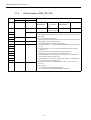
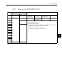
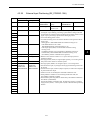
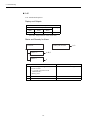
4.4 Subcommands - - - - - - - - - - - - - - - - - - - - - - - - - - - - - - - 4-49
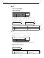
4.4.1
4.4.2
4.4.3
4.4.4
4.4.5
4.4.6
4.4.7
4.4.8
No Operation (NOP: 00H) - - - - - - - - - - - - - - - - - - - - - - - - - - - - - Read Parameter (PRM_RD:01H) - - - - - - - - - - - - - - - - - - - - - - - - Write Parameter (PRM_WR:02H) - - - - - - - - - - - - - - - - - - - - - - - - Read Alarm or Warning (ALM_RD:05H) - - - - - - - - - - - - - - - - - - - Write Non-volatile Parameter (PPRM_WR:1CH) - - - - - - - - - - - - - Request Latch Mode (LTMOD_ON:28H) - - - - - - - - - - - - - - - - - - - Release Latch Mode (LTMOD_OFF:29H) - - - - - - - - - - - - - - - - - - Status Monitoring (SMON:30H) - - - - - - - - - - - - - - - - - - - - - - - - - -
4-50
4-51
4-51
4-52
4-52
4-53
4-53
4-54
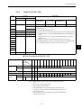
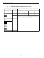
4.5 Command Data Field - - - - - - - - - - - - - - - - - - - - - - - - - - - 4-55
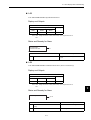
4.5.1
4.5.2
4.5.3
4.5.4
Latch Signal Field Specifications: LT_SGN - - - - - - - - - - - - - - - - - Option Field Specifications: OPTION - - - - - - - - - - - - - - - - - - - - - Status Field Specifications: STATUS - - - - - - - - - - - - - - - - - - - - - - Monitor Selection and Monitor Information Field Specifications:
SEL_MON1/2/3/4, MONITOR1/2/3/4 - - - - - - - - - - - - - - - - - - - - - 4.5.5 IO Monitor Field Specifications: IO_MON - - - - - - - - - - - - - - - - - - 4.5.6 Substatus Field Specifications: SUBSTATUS - - - - - - - - - - - - - - - - -
4-55
4-56
4-57
4-58
4-59
4-61
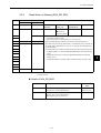
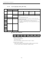
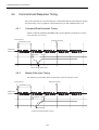
4.6 Command and Response Timing - - - - - - - - - - - - - - - - - - 4-62
4.6.1 Command Data Execution Timing - - - - - - - - - - - - - - - - - - - - - - - - - 4-62
4.6.2 Monitor Data Input Timing - - - - - - - - - - - - - - - - - - - - - - - - - - - - - - 4-62
4.7 Operation Sequence - - - - - - - - - - - - - - - - - - - - - - - - - - - 4-63
4.7.1
4.7.2
4.7.3
4.7.4
Operation Sequence for Managing Parameters Using a Controller Operation Sequence for Managing Parameters Using SERVOPACK
Operation Sequence When Being Servo ON - - - - - - - - - - - - - - - - Operation Sequence When OT (Overtravel Limit Switch) Signal
Is Input - - - - - - - - - - - - - - - - - - - - - - - - - - - - - - - - - - - - - - - - - - 4.7.5 Precaution for PSET = 1 When a Motion Command Execution
is Interrupted - - - - - - - - - - - - - - - - - - - - - - - - - - - - - - - - - - - - - - -
4-2
4-63
4-64
4-65
4-66
4-67
4.1 Specifications and Configuration
4.1
Specifications and Configuration
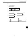
4.1.1
Specifications
Items that are not described in this chapter are based on the MECHATROLINK application
layer. For more details, refer to the following manuals.
• MECHATROLINK System User’s Manual (SIE-S800-26.1)
• MECHATROLINK Servo Command User’s Manual (SIE-S800-26.2)
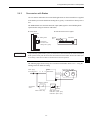
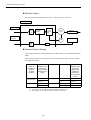
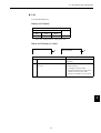
4.1.2
System Configuration
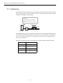
The following illustration shows system configuration. Refer to 3.5.3 Precautions for Wiring MECHATROLINK-II Cables for the number of stations possible to be connected.
Host controller
4
SERVOPACK
SERVOPACK
M
M
Servomot or
Servomotor
Fig. 4.1 System Configuration
4-3
4 MECHATROLINK-II Communications
4.2.1 Communications Settings
4.2
Switches for MECHATROLINK-II Communications Settings
This section describes the switch settings necessary for MECHATROLINK-II communications.
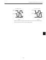
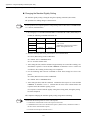
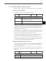
4.2.1
Communications Settings
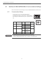
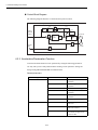
The SW2 DIP switch sets the MECHATROLINK-II
communications settings, as shown below. Settings that have
been changed are enabled when the power is turned OFF and
ON.
ON
OFF
1
2
3
4
SW2 (factory setting)
6
SW2
Bit 1
Bit 2
Bit 3
Bit 4
IMPORTANT
Item
Baud rate
Setting
Description
OFF
4 Mbps
ON
10 Mbps
Transmission
bytes
OFF
17 bytes
ON
30 bytes
Station address
OFF
Station address =
40H+SW1
ON
Station address =
50H+SW1
OFF
-
Reserved
Factory
Setting
A
5
B
4
3
D
ON
C
2
1 0 F
E
SW1 (factory setting)
ON
OFF
OFF
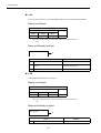
1. When connecting to a MECHATROLINK network, set bits 1 and 2 to OFF.
2. Baud rate: 4 Mbps, transmission bytes: 30 (bit 1 = OFF, bit 2 = ON) cannot be used.
4-4
7 8 9
4.2 Switches for MECHATROLINK-II Communications Settings
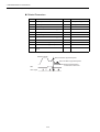
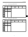
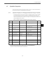
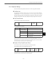
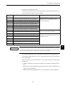
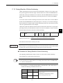
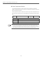
4.2.2
Setting the Transmission Cycle
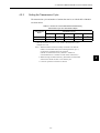
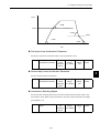
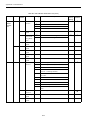
The transmission cycle and number of stations that can be set with the NS115 Module
are shown below.
Table 4.1 Number of Connectable Stations Determined by
Transmission Cycle and Transmission Bytes
Transmission
Bytes
Transmission Cycle
0.5
ms∗
1.0 ms
2.0 ms
3.0 ms
4.0 ms
17
6
14
30
30
30
30
3
8
20
30
30
* When the transmission cycle is 0.5 ms, set the communications cycle in
multiples of 1.0 ms.
Note: 1. When the number of stations actually connected is less than the
number of connectable stations, the remaining channels, up to 7,
can be used as communications retry channels.
(Number of communications retry channels = Number of
connnectable stations - Number of actual stations connected+1)
2. When not using communications retry, the number of connnectable
stations is the number in Table 4.1 increased by one.
3. Connect a repeater for more than 16 stations.
4-5
4
4 MECHATROLINK-II Communications
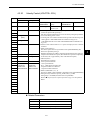
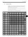
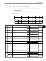
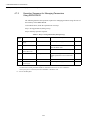
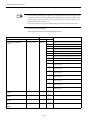
4.2.3 Setting the Station Address
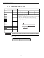
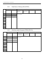
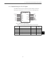
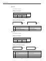
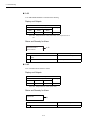
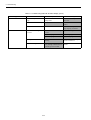
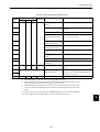
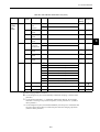
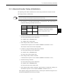
4.2.3
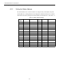
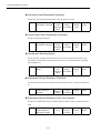
Setting the Station Address
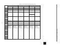
The station address is set as shown in Table 4.2, using the rotary switch (SW1) and piano
switch (SW2 bit 3). Settings that have been changed are enabled when the power is turned
OFF and ON. The factory setting for the station address is 41H (SW2 bit 3 = OFF, SW1 = 1).
Table 4.2 Station Address Settings
Bit 3 of
SW2
SW1
Station Address
Bit 3 of
SW2
SW1
Station Address
OFF
0
Disabled
ON
0
50H
OFF
1
41H
ON
1
51H
OFF
2
42H
ON
2
52H
OFF
3
43H
ON
3
53H
OFF
4
44H
ON
4
54H
OFF
5
45H
ON
5
55H
OFF
6
46H
ON
6
56H
OFF
7
47H
ON
7
57H
OFF
8
48H
ON
8
58H
OFF
9
49H
ON
9
59H
OFF
A
4AH
ON
A
5AH
OFF
B
4BH
ON
B
5BH
OFF
C
4CH
ON
C
5CH
OFF
D
4DH
ON
D
5DH
OFF
E
4EH
ON
E
5EH
OFF
F
4FH
ON
F
5FH
4-6
4.3 Main Commands
4.3
Main Commands
The following sections describe main command specific items that are unique to the NS115
Module.
The MECHATROLINK-II main commands are upwardly compatible with the MECHATROLINK commands. They use the first to the sixteenth bytes of the command and response
data. 03H is set in command byte 0, and 01H is returned to response byte 0.
4
4-7
4 MECHATROLINK-II Communications
4.3.1 No Operation (NOP: 00H)
4.3.1
Byte
1
No Operation (NOP: 00H)
NOP
Description
Command
Response
00H
00H
2
ALARM
3
STATUS
4
5
6
Processing
classifications
Network command group
Synchronization
classifications
Asynchronous
Processing time
Within transmission cycle
Subcommand
Can be used.
• Returns the status of the ALM, WARNG, and CMDRDY in STATUS bytes
only. All other bits are not used. The response will be NOP when the power is
turned ON until initialization has been completed, and during this time, the
following status will be returned: CMDRDY: 0.
• Can be used during any phase.
7
8
9
10
11
12
13
14
15
16
WDT
RWDT
17
For subcommands use.
Refer to 4.4
Subcommands.
For subcommands use.
Refer to 4.4
Subcommands.
18
19
20
21
22
23
24
25
26
27
28
29
4-8
4.3 Main Commands
4.3.2
Byte
1
Read Parameter (PRM_RD: 01H)
PRM_RD
Description
Command
Response
01H
01H
2
ALARM
3
STATUS
4
5
NO
NO
SIZE
SIZE
6
7
8
PARAMETER
9
10
11
12
13
14
15
16
WDT
Processing
classifications
Data communications command
group
Synchronization
classifications
Processing time
Refer to the folSubcommand
lowing description
Asynchronous
Cannot be used.
• Reads current operating parameters. The latest setting value, however, is read
for offline parameters. (The setting value is enabled with the Set Up Device
command (CONFIG).)
• A warning will occur and the command will be ignored in the following cases.
If a warning occurs, PARAMETER will not be dependable.
- If a digital operator is connected: MECHATROLINK-II command warning
(A.95)
- If SigmaWin and so on are connected: MECHATROLINK-II command
warning (A.95)
- If NO is not within range: Parameter setting warning (A.94)
- If SIZE does not match: Parameter setting warning (A.94)
• If communications are in progress with a Digital Operator, a command execution incomplete alarm (A.ED) may occur.
• For details on NO and SIZE, refer to Appendix B List of Parameters.Chapter
• Processing time
- 1 ms for reading NS115 Module parameter
- 4 to 6 ms for reading SGDH SERVOPACK parameter
RWDT
4-9
4
4 MECHATROLINK-II Communications
4.3.3 Write Parameter (PRM_WR: 02H)
4.3.3
Byte
1
Write Parameter (PRM_WR: 02H)
PRM_WR
Description
Command
Response
02H
02H
2
ALARM
3
STATUS
4
5
NO
NO
7
SIZE
SIZE
8
PARAMETER
PARAMETER
WDT
RWDT
6
9
10
11
12
13
14
15
16
Processing
classifications
Data communications command
group
Synchronization
classifications
Processing time
Refer to the folSubcommand
lowing description
Asynchronous
Cannot be used.
• Temporarily writes parameters and does not store them in E2PROM memory.
Offline parameters are enabled with the Set Up Device command (CONFIG)
after setting.
• Can be used during phases 2 and 3.
• A warning will occur and the command will be ignored in the following cases.
- During phases other than phases 2 and 3:
MECHATROLINK-II command warning (A.95)
- If a digital operator is connected: MECHATROLINK-II command warning
(A.95)
- If SigmaWin and so on are connected: MECHATROLINK-II command
warning (A.95)
- If NO is not within range: Parameter setting warning (A.94)
- If SIZE does not match: Parameter setting warning (A.94)
- If PARAMETER is not within range or would result in a calculation overflow: Parameter setting warning (A.94)
• If communications are in progress with a Digital Operator, a command execution incomplete alarm (A.ED) may occur.
• For details on NO, SIZE, and PARAMETER, refer to Appendix B List of
Parameters.
• Processing time
- 1 ms when writing NS115 Module parameter
- 4 to 6 ms when writing SGDH SERVOPACK parameter
4-10
4.3 Main Commands
4.3.4
Read ID (ID_RD: 03H)
Byte
ID_RD
Description
Command
Response
03H
03H
1
2
ALARM
3
STATUS
4
5
DEVICE_COD
DEVICE_COD
6
OFFSET
OFFSET
7
SIZE
SIZE
8
ID
9
10
11
Processing
classifications
Data communica- Synchronization
classifications
tions command
group
Processing time
Within 1 sec
Asynchronous
Subcommand
Cannot be used.
• Reads the ID. The corresponding DEVICE_COD is shown in the table on the
following page.
• Can be used during phases 2 and 3.
• A warning will occur and the command will be ignored in the following cases.
- If a digital operator is connected: MECHATROLINK-II command warning
(A.95)
- If SigmaWin and so on are connected: MECHATROLINK-II command
warning (A.95)
- If SIZE (1 to 8) does not match: Parameter setting warning (A.94)
• If communications are in progress with a digital operator or SigmaWin and so
on, a command execution incomplete alarm (A.ED) may occur.
12
4
13
14
15
16
WDT
RWDT
The ID contents of DEVICE_COD
Type/Name
OFFSET
00
01
02
03
04
05
06
07
08
09
D
H
−
0
1
A
E
00
0A
0B
0C
2
1
0E 0F 10
DEVICE_
COD
Model
00H
S
G
Software
Ver.
02H
33
00
Encoder Software Ver.
12H
04
00
Servomotor Model
20H
S
G
M
A
H
−
0
1
A
A
A
J
U
S
P
−
N
S
1
1
5
00
01
00
SERVOPACK
NS115
Module
50H
Model
Software
Ver.
52
H
Note: 1. Model numbers appear in ASCII code, with the last section as
“00.”
2. The software version is binary data.
3. Spaces indicate unspecified data.
4. If the SERVOPACK is not operating since an alarm E0, E1, E2,
EA, EB, EC occurs at power ON, the SERVOPACK and the servomotor model are “00.”
5. If the encoder cable is not connected,the servomotor model and the
encoder version are “00.”
4-11
00
4 MECHATROLINK-II Communications
4.3.5 Set Up Device (CONFIG: 04H)
4.3.5
Byte
1
Set Up Device (CONFIG: 04H)
CONFIG
Description
Command
Response
04H
04H
2
ALARM
3
STATUS
Processing
classifications
Control command group
Synchronization
classifications
Asynchronous
Processing time
Within 4 s + α∗
Subcommand
Cannot be used.
4
5
6
7
8
9
10
11
12
13
• Recalculates all currently set parameters and initializes positions, signals, etc.
• Can be used during phases 2 and 3.
• The SERVOPACK will change to Servo OFF if this command is received
when the SERVOPACK is Servo ON.
• A warning will occur and the command will be ignored in the following cases.
- During phase 1: MECHATROLINK-II command warning (A.95)
- If a digital operator is connected: MECHATROLINK-II command warning
(A.95)
- If SigmaWin and so on are connected: MECHATROLINK-II command
warning (A.95)
• The following table shows status and output signal during CONFIG command
execution.
• If communications are in progress with a Digital Operator, a command warning (A.ED) may occur.
14
15
16
WDT
RWDT
* +α refers to the amount of delay that is set by parameter for turning the Servo OFF during braking control.
Status and Output Signal during CONFIG Command Execution
Status and
Output Signal
Before CONFIG
During CONFIG
After CONFIG
ALM (status)
Current status
Current status
Current status
CMDRDY (status)
1
0
1
Other status
Current status
Not specified
Current status
ALARM (code)
Alarms currently
occurred
Alarms currently
occurred
Alarms currently
occurred
ALM
(CN1 output signal)
Current status
Current status
Current status
/S-RDY
(CN1 output signal)
Current status
OFF
Current status
Other output signals
Current status
Not specified
Current status
4-12
4.3 Main Commands
4.3.6
Byte
Read Alarm or Warning (ALM_RD: 05H)
ALM_RD
Description
Command
Response
05H
05H
Processing classifications
Control command group
Synchronization
classifications
Asynchronous
2
ALARM
Processing time
Refer to
Details of
ALM_RD_MOD.
Subcommand
Cannot be used.
3
STATUS
1
4
5
ALM_RD_MOD ALM_RD_MOD
6
ALM_DATA
7
8
9
10
11
12
• Reads the following alarm or warning status.
- Current alarm/warning status
- Alarm status history* (warning history is not preserved.)
• The ALM_RD_MOD specifications are shown in the following table.
• The latest error and warning information is contained from byte 6 onwards of
the ALM_DATA. When there are no errors or warnings, the remaining bytes
are normal (99H).
• A warning will occur and the command will be ignored in the following cases.
- If a digital operator is connected: MECHATROLINK-II command warning
(A.95)
- If SigmaWin and so on are connected: MECHATROLINK-II command
warning (A.95)
- If ALM_RD_MOD is not within range: Parameter setting warning (A.94)
13
14
15
16
WDT
RWDT
* Alarm occurrence history is saved on E2PROM, and will not be lost if
power goes OFF.
Details of ALM_RD_MOD
ALM_RD_MOD
Description
Processing
Time
0
Read current alarm/warning status
10 items max. (sixth to fifteenth byte)
Within communications cycle
1
Read alarm status history
10 items max. (sixth to fifteenth byte)
(Warning history is not preserved.)
Within 2 s
4-13
4
4 MECHATROLINK-II Communications
4.3.7 Clear Alarm/Warning (ALM_CLR: 06H)
4.3.7
Byte
1
Clear Alarm/Warning (ALM_CLR: 06H)
ALM_CLR
Description
Command
Response
06H
06H
2
ALARM
3
STATUS
4
5
ALM_CLR_MOD ALM_CLR_MOD
6
7
8
9
10
11
12
Processing
classifications
Control command
group
Synchronization
classifications
Processing time
Refer to
Subcommand
Details of
ALM_CLR_MOD.
Asynchronous
Cannot be used.
• Clears the following alarm or warning status.
- Current alarm/warning status
- Alarm status history * (warning history is not preserved.)
• Can be used during any phase.
• The ALM_CLR_MOD specifications are shown in the following table.
• A warning will occur and the command will be ignored in the following cases.
- During phases other than phases 2 and 3:
MECHATROLINK-II command warning (A.95)
- If a digital operator is connected: MECHATROLINK-II command warning
(A.95)
- If SigmaWin and so on are connected: MECHATROLINK-II command
warning (A.95)
- If ALM_CLR_MOD is not within range: Parameter setting warning (A.94)
13
14
15
16
WDT
RWDT
* Alarm occurrence history is saved on E2PROM, and will not be lost if
power goes OFF.
Details of ALM_CLR_MOD
ALM_CLR_MOD
Description
0
Clear current alarm/warning status
Within 200 ms
1
Clear alarm status history
Within 2 s
4-14
Processing Time
4.3 Main Commands
4.3.8
Byte
1
Start Synchronous Communications (SYNC_SET: 0DH)
SYNC_SET
Description
Command
Response
0DH
0DH
2
ALARM
3
STATUS
4
5
6
7
8
9
10
11
Processing
classifications
Network command group
Synchronization
classifications
Asynchronous
Processing time
Transmission
cycle or more
Subcommand
Cannot be used.
• Starts synchronous communications. Switches from phase 2 to phase 3.
• Processing is completed at the WDT changing edge.
However, if WDT errors are being masked by parameter Pn800.0, processing
is completed when this command is received.
• During phase 1, a MECHATROLINK-II command warning (A.95) will occur
and the command will be ignored.
• During phase 3, the command will be ignored (without a warning).
• The SERVOPACK will change to Servo OFF if this command is received
when the SERVOPACK is Servo ON during phase 2.
• The synchronous communications have to be restarted using this command
when the MECHATROLINK-II communications error (A.E6) or the
MECHATROLINK-II synchronization error (A.E5) occurs.
12
13
14
15
16
WDT
RWDT
4-15
4
4 MECHATROLINK-II Communications
4.3.9 MECHATROLINK-II Connection (CONNECT: 0EH)
4.3.9
MECHATROLINK-II Connection (CONNECT: 0EH)
Byte
Byte
CONNECT
Command
Response
1
0EH
0EH
2
ALARM
3
STATUS
4
5
VER
VER
6
COM_MOD
COM_MOD
7
COM_TIM
COM_TIM
WDT
RWDT
8
9
10
11
12
13
Description
Description
Processing
classifications
Network command group
Synchronization
classifications
Asynchronous
Processing time
Communications
cycle or more
Subcommand
Cannot be used.
• Establishes a MECHATROLINK-II connection. Sets the communications
mode according to COM_MOD.
• VER: Version
• Set VER to 21H (Ver. 2.1).
• COM_MOD: Communications mode. Refer to the following table.
• COM_TIM: Communications cycle
Set the multiple number of transmission cycle in the range of 1 to 32.
1 [ms] ≤ transmission cycle [ms] × COM_TIM ≤ 32 [ms]
(Set the multiple number of 1 [ms].)
• A warning will occur and the command will be ignored in the following cases.
- If COM_MOD is not within range: Parameter setting warning (A.94)
- If COM_TIM is not within range: Parameter setting warning (A.94)
- If the transmission bytes is 17, and SUBCMD is 1: Parameter setting
warning (A.94)
14
15
16
Details of COM_MOD
D7
D6
D5
D4
SUBCMD
0
0
0
D3
D2
DTMOD
• SYNCMOD*:
0: Asynchronous communication
(The SERVOPACK changes communication to phase 2.)
1: Synchronous communication
(The SERVOPACK changes communication to phase 3.)
∗ Set SYNC_SET when the SERVOPACK changes communication to phase 3.
• DTMOD: Data transfer method
00, 11: Single transfer
01: Consecutive transfer
10: Multiple transfers (not supported)
• SUBCMD:
0: Subcommand not used
1: Subcommand used
4-16
D1
D0
SYNCMOD
0
Warning/alarm
Phase 1
SYNCMOD=0
Phase 2
SYNC_SET
Phase 3
SYNCMOD=1
4.3 Main Commands
4.3.10
Byte
1
Disconnection (DISCONNECT: 0FH)
DISCONNECT
Command
Response
0FH
0FH
2
ALARM
3
STATUS
4
5
6
7
8
Description
Processing
classifications
Network command group
Synchronization
classifications
Asynchronous
Processing time
Communications
cycle or more
Subcommand
Cannot be used.
• Releases the MECHATROLINK-II connection. The SERVOPACK changes
communication to phase 1.
• Can be used during any phase.
• When this command is received, the following operations will be performed.
- The SERVOPACK changes communication to phase 1.
- The SERVOPACK changes to Servo OFF.
- The reference point setting will become invalid.
9
10
11
4
12
13
14
15
16
WDT
RWDT
4-17
4 MECHATROLINK-II Communications
4.3.11 Read Non-volatile Parameter (PPRM_RD: 1BH)
4.3.11
Byte
1
Read Non-volatile Parameter (PPRM_RD: 1BH)
PPRM_RD
Description
Command
Response
1BH
1BH
2
ALARM
3
STATUS
4
5
NO
Processing
classifications
Data communica- Synchronization
tions command
classifications
group
Processing time
Within communications cycle
SIZE
8
9
10
11
12
13
14
15
16
WDT
Cannot be used.
• This command is not supported.
• When this command is received, a MECHATROLINK-II command warning
(A.95) will occur and the command will be ignored.
6
7
Subcommand
Asynchronous
RWDT
4-18
4.3 Main Commands
4.3.12
Byte
1
Write Non-volatile Parameter (PPRM_WR: 1CH)
PPRM_WR
Description
Command
Response
1CH
1CH
2
ALARM
3
STATUS
4
5
NO
NO
6
7
SIZE
SIZE
8
PARAMETER
PARAMETER
9
10
11
12
13
14
15
16
WDT
RWDT
Processing
classifications
Data communica- Synchronization
tions command
classifications
group
Processing time
Within 200 ms
Subcommand
Asynchronous
Cannot be used.
• Saves parameters in E2PROM. If parameters are online parameters, those
parameters will become effective immediately.
Offline parameters are enabled with the Set Up Device command (CONFIG)
after setting.
• Can be used during phases 2 and 3.
• A warning will occur and the command will be ignored in the
following cases.
- During phase 1: MECHATROLINK-II command warning (A.95)
- If a digital operator is connected: MECHATROLINK-II command warning
(A.95)
- If SigmaWin and so on are connected: MECHATROLINK-II command
warning (A.95)
- If NO is not within range: Parameter setting warning (A.94)
- If SIZE does not match: Parameter setting warning (A.94)
- If PARAMETER is not within range or would result in a calculation
overflow: Parameter setting warning (A.94)
• If communications are in progress with a Digital Operator, a command execution incomplete alarm (A.ED) may occur.
• For details on NO, SIZE and PARAMETER, refer to the Appendix B List of
Parameters.
4-19
4
4 MECHATROLINK-II Communications
4.3.13 Set Coordinates (POS_SET: 20H)
4.3.13
Byte
1
Set Coordinates (POS_SET: 20H)
POS_SET
Description
Command
Response
20H
20H
2
ALARM
3
STATUS
Processing
classifications
Data communica- Synchronization
tions command
classifications
group
Processing time
Within 200 ms
PS_SUBCMD
PS_SUBCMD
6
POS_DATA
POS_DATA
WDT
RWDT
Subcommand
Cannot be used.
• Sets coordinates. REFE can also enable zero point (ZPOINT) and software
limits.
• Can be used during phases 2 and 3.
• PS_SUBCMD: Refer to the following table for coordinate setting modes.
• Set position in POS_DATA.
• A warning will occur and the command will be ignored in the following cases.
- During phase 1: MECHATROLINK-II command warning (A.95)
- If a number not within the range is set for PS_SUBCMD: Parameter setting
warning (A.94)
4
5
Asynchronous
7
8
9
10
11
12
13
14
15
16
Details of PS_SUBCMD
D7
D6
D5
D4
REFE
0
0
0
D3
D2
D1
D0
POS_SEL
• REFE: Sets reference point.
0: Does not set reference point.
1: Sets reference point.
The zero point is enabled, ZPOINT and software limits are enabled.
• POS_SEL: Selects coordinates.
3: When APOS (feedback position in machine coordinate system) is selected,
it is also set in the reference and machine coordinate system.
4-20
4.3 Main Commands
4.3.14
Byte
1
Apply Brake (BRK_ON: 21H)
BRK_ON
Description
Command
Response
21H
21H
2
ALARM
3
STATUS
4
5
MONITOR 1
6
7
Processing
classifications
Control command group
Synchronization
classifications
Asynchronous
Processing time
Within communications cycle
Subcommand
Cannot be used.
• Applies brake. This command is enabled when Pn005.0 is set to 1.
• Can be used during phases 2 and 3.
• A warning will occur and the command will be ignored in the following cases.
- During phase 1: MECHATROLINK-II command warning (A.95)
- If Pn005.0 is set to 0: MECHATROLINK-II command warning (A.95)
• Brake signal output timing
8
9
MONITOR 2
10
11
4
12
13
SEL_MON 1/2
14
SEL_MON 1/2
IO_MON
Within 3 ms
15
16
WDT
IMPORTANT
RWDT
When Pn005.0 is set to 1, the brake interlock must be processed at the controller instead of the Servo.
Related Parameter
Pn No.
Pn005.0
Description
Brake operation
4-21
4 MECHATROLINK-II Communications
4.3.15 Release Brake (BRK_OFF: 22H)
4.3.15
Byte
1
Release Brake (BRK_OFF: 22H)
BRK_OFF
Description
Command
Response
22H
22H
2
ALARM
3
STATUS
4
5
MONITOR 1
6
7
Processing
classifications
Control command group
Synchronization
classifications
Asynchronous
Processing time
Within communications cycle
Subcommand
Cannot be used.
• Applies brake. This command is enabled when Pn005.0 is set to 1.
• Can be used during phases 2 and 3.
• A warning will occur and the command will be ignored in the following cases.
- During phase 1: MECHATROLINK-II command warning (A.95)
- If Pn005.0 is set to 0: MECHATROLINK-II command warning (A.95)
• Brake signal output timing
8
9
MONITOR 2
10
11
12
13
SEL_MON1/2
14
SEL_MON1/2
IO_MON
Within 3 ms
15
16
WDT
IMPORTANT
RWDT
When Pn005.0 is set to 1, the brake interlock must be processed at the controller instead of the Servo.
Related Parameter
Pn No.
Pn005.0
Description
Brake operation
4-22
4.3 Main Commands
4.3.16
Byte
1
Turn Sensor ON (SENS_ON: 23H):
SENS_ON
Description
Command
Response
23H
23H
2
ALARM
3
STATUS
4
5
MONITOR 1
6
7
8
9
MONITOR 2
Processing
classifications
Control command group
Synchronization
classifications
Asynchronous
Processing time
Within 2 sec
Subcommand
Cannot be used.
• Obtains the initial position data when an absolute encoder is used.
• Position data is received from the encoder and the current position is created.
• The reference point, zero point (ZPOINT), and software limits will be enabled
when an absolute encoder is used.
• Can be used during phases 2 and 3.
• If an incremental encoder is being used, the command will be ignored.
• During phase 1, a MECHATROLINK-II command warning (A.95) will occur
and the command will be ignored.
10
11
12
13
SEL_MON 1/2
14
4
SEL_MON 1/2
IO_MON
15
16
WDT
RWDT
4-23
4 MECHATROLINK-II Communications
4.3.17 Turn Sensor OFF (SENS_OFF: 24H)
4.3.17
Byte
1
Turn Sensor OFF (SENS_OFF: 24H)
SENS_OFF
Description
Command
Response
24H
24H
2
ALARM
3
STATUS
4
5
MONITOR 1
6
7
Processing
classifications
Control command group
Synchronization
classifications
Asynchronous
Processing time
Within 500 ms
Subcommand
Cannot be used.
• Turns sensor OFF. The position data is not specified.
• The reference point, zero point (ZPOINT), and software limits will be enabled.
• Can be used during phases 2 and 3.
• If an incremental encoder is being used, the command will be ignored.
• During phase 1, a MECHATROLINK-II command warning (A.95) will occur
and the command will be ignored.
8
9
MONITOR 2
10
11
12
13
SEL_MON 1/2
14
SEL_MON 1/2
IO_MON
15
16
WDT
RWDT
4-24
4.3 Main Commands
4.3.18
Byte
1
Stop Motion (HOLD: 25H)
HOLD
Command
Response
25H
25H
2
3
Description
ALARM
OPTION
STATUS
HOLD_MOD
MONITOR1
4
5
6
7
8
9
MONITOR2
10
11
12
13
SEL_MON 1/2
14
SEL_MON 1/2
IO_MON
15
16
WDT
RWDT
17
For subcommands use.
Refer to 4.4
Subcommands.
For subcommands use.
Refer to 4.4
Subcommands.
18
19
Processing
classifications
Motion command
group
Synchronization
classifications
Asynchronous
Processing time
Within communications cycle
Subcommand
Can be used.
• From current motion status, performs a deceleration stop and positioning
according to the deceleration value set in the parameters.
• Can be used during phases 2 and 3.
• During phase 1, a MECHATROLINK-II command warning (A.95) will occur
and the command will be ignored.
• OPTION can be selected. Refer to 4.5.2 Option Field Specifications: OPTION
for details.
• Use DEN (output complete) to confirm the completion of motion processing.
• Latch processing, which is dependent on LATCH, EX_POSING, and SVCTRL will be cancelled.
• ZRET latch processing and ZRET zero point alignment will be cancelled.
• Upon completion of this command, the reference position (POS) must be read,
and the controller coordinate system must be set up.
• The stop method can be selected using HOLD_MOD.
0: Decelerate to a stop according to the deceleration parameter.
1: Stop immediately (output stop).
20
21
22
23
24
25
26
27
28
29
Related Parameters
Pn No.
Description
Pn80D
First-step Linear Deceleration Parameter
Pn80E
Second-step Linear Deceleration Parameter
Pn80F
Deceleration Parameter Switching Speed
4-25
4
4 MECHATROLINK-II Communications
4.3.19 Request Latch Mode (LTMOD_ON: 28H)
4.3.19
Byte
Request Latch Mode (LTMOD_ON: 28H)
LTMOD_ON
Description
Command
Response
1
28H
28H
2
LT_SGN
ALARM
3
STATUS
4
5
MONITOR1
6
7
8
9
MONITOR2
10
11
12
13
SEL_MON 1/2
14
SEL_MON 1/2
IO_MON
15
16
WDT
RWDT
17
For subcommands use.
Refer to 4.4
Subcommands.
For subcommands use.
Refer to 4.4
Subcommands.
18
19
20
21
22
Processing
classifications
Control command group
Synchronization
classifications
Asynchronous
Processing time
Within communications cycle
Subcommand
Can be used.
• Sets the modal latch mode. If a latch signal is input during modal latch mode,
position latching will be performed.
• Can be used during phases 2 and 3.
• A MECHATROLINK-II command warning (A.95) will occur and the command will be ignored in the following cases.
- During phase 1.
- If LTMOD_ON and LATCH, ZRET, EX_POSING, or SVCTRL are
executed simultaneously, or if LTMOD_ON is received during LATCH,
ZRET, EX_POSING, or SVCTRL execution (the LTMOD_ON command
will be ignored).
• A latch signal can be selected using LT_SGN. Refer to 4.5.1 Latch Signal
Field Specifications (LT_SGN).
• Use response command 28H, CMDRDY = 1 to confirm that the Request Latch
Mode command has been received.
• It takes 4 ms max. for the Request Latch Mode command to start.
• Confirm that L_CMP is 1 in STATUS at the completion of latching.
- When there is monitor data such as SMON or POSING appended to the
command response, LPOS is forcefully returned to MONITOR2.
- When there is no monitor data such as PRM_RD or ALM_RD appended to
the command response, confirm that L_CMP is 1 in STATUS, then use a
command that has monitor data such as SMON in the response and select
LPOS to confirm.
• Once the latch operation has been performed, it will not be performed again
even if a latch signal is input. Send a new LTMOD_ON command.
• Interference with another latch mode command
- If LATCH, ZRET, EX_POSING, or SVCTRL are received during modal
latch mode, the new command is enabled.
23
24
25
26
27
28
29
Related Parameters
Pn No.
Description
Pn511
Input Signal Selections 5
Pn820
Latching Area Upper Limit
Pn822
Latching Area Lower Limit
4-26
4.3 Main Commands
4.3.20
Byte
1
Release Latch Mode (LTMOD_OFF: 29H)
LTMOD_OFF
Command
Response
29H
29H
2
ALARM
3
STATUS
4
5
MONITOR1
6
7
8
9
MONITOR2
10
11
Description
Processing
classifications
Control command group
Synchronization
classifications
Asynchronous
Processing time
Within communications cycle
Subcommand
Can be used.
• Releases the modal latch mode.
• Can be used during phases 2 and 3.
• A MECHATROLINK-II command warning (A.95) will occur and the command will be ignored in the following cases.
- During phase 1.
- If LTMOD_OFF and LATCH, ZRET, EX_POSING, or SVCTRL are
executed simultaneously, or if LTMOD_OFF is received during LATCH,
ZRET, EX_POSING, or SVCTRL execution (the LTMOD_OFF will be
ignored).
• Check that CMDRDY is 1 to confirm that the Release Latch Mode command
has been received.
- It takes 4 ms max. for the Release Latch Mode command to start.
12
13
SEL_MON 1/2
14
SEL_MON 1/2
IO_MON
15
16
WDT
RWDT
17
For subcommands use.
Refer to 4.4
Subcommands.
For subcommands use.
Refer to 4.4
Subcommands.
18
19
20
21
22
23
24
25
26
27
28
29
4-27
4
4 MECHATROLINK-II Communications
4.3.21 Status Monitoring (SMON: 30H)
4.3.21
Byte
1
Status Monitoring (SMON: 30H)
SMON
Description
Command
Response
30H
30H
2
ALARM
3
STATUS
4
5
MONITOR1
Processing
classifications
Control command group
Synchronization
classifications
Asynchronous
Processing time
Within communications cycle
Subcommand
Can be used.
• Reads the current status of the Servo.
• Can be used during phases 2 and 3.
• During phase 1, a MECHATROLINK-II command warning (A.95) will occur
and the command will be ignored.
6
7
8
9
MONITOR2
10
11
12
13
SEL_MON 1/2
14
SEL_MON 1/2
IO_MON
15
16
WDT
RWDT
17
For subcommands use.
Refer to 4.4
Subcommands.
For subcommands use.
Refer to 4.4
Subcommands.
18
19
20
21
22
23
24
25
26
27
28
29
4-28
4.3 Main Commands
4.3.22
Byte
1
Servo ON (SV_ON: 31H)
SV_ON
Command
Response
31H
31H
2
3
Description
ALARM
OPTION
STATUS
4
5
MONITOR1
6
7
8
9
MONITOR2
10
11
12
13
SEL_MON 1/2
14
SEL_MON 1/2
IO_MON
Processing
classifications
Control command group
Processing time
Within 50 ms nor- Subcommand
mally
WDT
RWDT
17
For subcommands use.
Refer to 4.4
Subcommands.
For subcommands use.
Refer to 4.4
Subcommands.
18
19
Asynchronous
Can be used.
• The SERVOPACK changes to Servo ON.
• Can be used during phases 2 and 3.
• A MECHATROLINK-II command warning (A.95) will occur and the command will be ignored in the following cases.
- During phase 1
- During alarm occurrence (when ALM of STATUS is 1)
- If SENS_ON has not been completed when the absolute encoder is
used
• OPTION can be selected. Refer to 4.5.2 Option Field Specifications:
OPTION for details.
• For linear motors not equipped with a pole sensor, it takes 10 seconds max.
until the SERVOPACK changes to Servo ON the first time because the pole
must be detected.
• Upon completion of this command, the reference position (POS) must be read,
and the controller coordinate system must be set up.
15
16
Synchronization
classifications
20
21
22
23
24
25
26
27
28
29
4-29
4
4 MECHATROLINK-II Communications
4.3.23 Servo OFF (SV_OFF: 32H)
4.3.23
Byte
1
Servo OFF (SV_OFF: 32H)
SV_OFF
Description
Command
Response
32H
32H
2
ALARM
3
STATUS
4
5
MONITOR1
Processing
classifications
Control command group
Synchronization
classifications
Asynchronous
Processing time
Follow settings
from Pn506 to
Pn508.
Subcommand
Can be used.
• The SERVOPACK changes to Servo OFF.
• Can be used during phases 2 and 3.
• During phase 1, a MECHATROLINK-II command warning (A.95) will occur
and the command will be ignored.
6
7
8
9
MONITOR2
10
11
12
13
SEL_MON 1/2
14
SEL_MON 1/2
IO_MON
15
16
WDT
RWDT
17
For subcommands use.
Refer to 4.4
Subcommands.
For subcommands use.
Refer to 4.4
Subcommands.
18
19
20
21
22
23
24
25
26
27
28
29
4-30
4.3 Main Commands
4.3.24
Byte
1
Interpolation Feed (INTERPOLATE: 34H)
INTERPOLATE
Command
Response
34H
34H
Processing
classifications
Motion command
group
Synchronization
classifications
Synchronous
ALARM
Processing time
Within communications cycle
Subcommand
Can be used.
OPTION
STATUS
TPOS
MONITOR1
VFF
MONITOR2
SEL_MON 1/2
SEL_MON 1/2
• Starts interpolation feeding. Speed feed forward (VFF) can be specified simultaneously.
• Can be used during phases 2 and 3.
• A warning will occur and the command will be ignored in the following cases.
- During phases other than phase 3:
MECHATROLINK-II command warning (A.95)
- If the SERVOPACK is Servo OFF:
MECHATROLINK-II command warning (A.95)
- If the output speed (difference from the previous target position (TPOS))
exceeds the limit: Parameter setting warning (A.94)
- If VFF is not within the setting range: Parameter setting warning (A.94)
- OPTION can be selected. Refer to 4.5.2 Option Field Specifications: OPTION
for details.
• Use DEN (output complete) to confirm the completion of position reference
output.
2
3
4
5
6
7
8
9
10
11
12
13
Description
14
IO_MON
15
16
WDT
RWDT
17
For subcommands use.
Refer to 4.4
Subcommands.
For subcommands use.
Refer to 4.4
Subcommands.
18
19
20
21
22
23
24
25
26
27
28
29
4-31
4
4 MECHATROLINK-II Communications
4.3.25 Positioning (POSING: 35H)
4.3.25
Byte
1
Positioning (POSING: 35H)
POSING
Command
Response
35H
35H
2
3
Description
ALARM
OPTION
STATUS
TPOS
MONITOR1
TSPD
MONITOR2
SEL_MON 1/2
SEL_MON 1/2
4
5
6
7
8
9
10
11
12
13
14
IO_MON
15
16
WDT
RWDT
17
For subcommands use.
Refer to 4.4
Subcommands.
For subcommands use.
Refer to 4.4
Subcommands.
18
19
Processing
classifications
Motion command
group
Synchronization
classifications
Synchronous
Processing time
Within communications cycle
Subcommand
Can be used.
• Performs positioning at the target position (TPOS) using the target speed
(TSPD).
• Can be used during phases 2 and 3.
• A warning will occur and the command will be ignored in the following cases.
- During phase 1: MECHATROLINK-II command warning (A.95)
- If the SERVOPACK is Servo OFF: MECHATROLINK-II command warning
(A.95)
- If the target speed (TSPD) exceeds the limit: Parameter setting warning
(A.94)
• OPTION can be selected. Refer to 4.5.2 Option Field Specifications: OPTION
for details.
• The target position (TPOS) is a signed 4 bytes. It is set using an absolute position in the reference coordinate system.
• The target speed (TSPD) is an unsigned 4 bytes. It is set using units/s.
• Changes can be made to the target position and target speed during movement.
• Use DEN (output complete) to confirm the completion of position reference
output.
• The maximum positioning distance referenced by one POSING command is
2147483647 (7FFFFFFFH).
Execute the POSING command so that the following equation is satisfied:
Target position (TPOS) − current position (POS) ≤ The maximum positioning
distance
20
21
22
23
24
25
26
27
28
29
Related Parameters
Pn No.
Description
Pn80A
First-step Linear Acceleration Parameter
Pn80B
Second-step Linear Acceleration Parameter
Pn80C
Acceleration Parameter Switching Speed
Pn80D
First-step Linear Deceleration Parameter
Pn80E
Second-step Linear Deceleration Parameter
Pn80F
Deceleration Parameter Switching Speed
4-32
4.3 Main Commands
4.3.26
Byte
1
Constant Speed Feed (FEED: 36H)
FEED
Command
Response
36H
36H
2
3
Description
ALARM
OPTION
STATUS
4
5
MONITOR1
6
7
8
9
TSPD
MONITOR2
SEL_MON 1/2
SEL_MON 1/2
10
11
12
13
14
IO_MON
15
16
WDT
RWDT
17
For subcommands use.
Refer to 4.4
Subcommands.
For subcommands use.
Refer to 4.4
Subcommands.
18
19
Processing
classifications
Motion command
group
Synchronization
classifications
Asynchronous
Processing time
Within communications cycle
Subcommand
Can be used.
• Performs constant speed feeding using the target speed (TSPD). Use the Stop
Motion command (HOLD: 25H) to stop the constant speed feeding. The position control loop is effective during this command.
• Can be used during phases 2 and 3.
• A command warning will occur and the command will be ignored in the following cases.
- During phase 1: MECHATROLINK-II command warning (A.95)
- If the SERVOPACK is Servo OFF:
MECHATROLINK-II command warning (A.95)
- If the target speed (TSPD) exceeds the limit: Parameter setting warning
(A.94)
• OPTION can be selected. Refer to 4.5.2 Option Field Specifications:
OPTION for details.
• The target speed (TSPD) is a signed 4 bytes. The direction is determined by
the sign. It is set using units/s.
• Changes can be made to the target speed during movement.
• Use DEN (output complete) to confirm the completion of position reference
output.
20
21
22
23
24
25
26
27
28
29
4-33
4
4 MECHATROLINK-II Communications
4.3.26 Constant Speed Feed (FEED: 36H)
Related Parameters
Pn No.
Description
Pn80A
First-step Linear Acceleration Parameter
Pn80B
Second-step Linear Acceleration Parameter
Pn80C
Acceleration Parameter Switching Speed
Pn80D
First-step Linear Deceleration Parameter
Pn80E
Second-step Linear Deceleration Parameter
Pn80F
Deceleration Parameter Switching Speed
4-34
4.3 Main Commands
4.3.27
Byte
Interpolation Feeding with Position Detection (LATCH: 38H)
LATCH
Description
Command
Response
1
38H
38H
2
LT_SGN
ALARM
3
OPTION
STATUS
TPOS
MONITOR1
VFF
MONITOR2
SEL_MON 1/2
SEL_MON 1/2
4
5
6
7
8
9
10
11
12
13
14
IO_MON
15
16
WDT
RWDT
17
For subcommands use.
Refer to 4.4
Subcommands.
For subcommands use.
Refer to 4.4
Subcommands.
18
19
20
21
22
Processing
classifications
Motion command
group
Synchronization
classifications
Synchronous
Processing time
Within communications cycle
Subcommand
Can be used.
• Performs interpolation feeding and latches the position using the latch signal
simultaneously. Sends speed feedforward (VFF) simultaneously, too.
• If the latch signal is input, the position when the input is received is recorded
as the counter latch position (LPOS) and LPOS will be indicated as the
MONITOR2 forcibly for one communications cycle.
• Can be used during phases 2 and 3.
• A command warning will occur and the command will be ignored in the following cases.
- During phases other than phase 3:
MECHATROLINK-II command warning (A.95)
- If the SERVOPACK is Servo OFF:
MECHATROLINK-II command warning (A.95)
- If the output speed (difference from the previous target position
(TPOS)) exceeds the limit: Parameter setting warning (A.94)
- If VEF is not within the setting range:
Parameter setting warning (A.94)
- If LTMOD_-ON/OFF is received during LATCH execution or simultaneously: MECHATROLINK-II command warning (A.95)
(the LTMOD_ON/OFF commands will be ignored.)
• LT_SGN can be selected. Refer to 4.5.1 Latch Signal Field Specifications:
LT_SGN (LT_SGN).
• OPTION can be selected. Refer to 4.5.2 Option Field Specifications:
OPTION for details.
• Use DEN (output complete) to confirm the motion completion.
• It takes 4 ms max. for the Request Latch Mode command to start.
• If LATCH command is received during modal latch mode, the LACTH command is enabled.
23
24
25
26
27
28
29
4-35
4
4 MECHATROLINK-II Communications
4.3.27 Interpolation Feeding with Position Detection (LATCH: 38H)
Related Parameters
Pn No.
Description
Pn511
Input Signal Selections 5
Pn820
Latching Area Upper Limit
Pn822
Latching Area Lower Limit
4-36
4.3 Main Commands
4.3.28
Byte
External Input Positioning (EX_POSING: 39H)
EX_POSING
Description
Command
Response
1
39H
39H
2
LT_SGN
ALARM
3
OPTION
STATUS
TPOS
MONITOR1
TSPD
MONITOR2
SEL_MON 1/2
SEL_MON 1/2
4
5
6
7
8
9
10
11
12
13
14
I/O_MON
15
16
WDT
RWDT
17
For subcommands use.
Refer to 4.4
Subcommands.
For subcommands use.
Refer to 4.4
Subcommands.
18
19
20
21
22
23
24
25
26
Processing
classifications
Motion command
group
Synchronization
classifications
Asynchronous
Processing time
Within communications cycle
Subcommand
Can be used.
• Moves toward the target position (TPOS) at the target speed (TSPD). When a
latch signal is input midway, positioning is performed according to the final
travel distance for external position specified in the parameter. When no latch
signal is input, positioning is performed for the target position.
• Can be used during phases 2 and 3.
• A command warning will occur and the command will be ignored in the following cases.
- During phase 1: MECHATROLINK-II command warning (A.95)
- If the SERVOPACK is Servo OFF:
MECHATROLINK-II command warning (A.95)
- If the target speed (TSPD) exceeds the limit: Parameter setting
warning (A.94)
- If LTMOD_ON/OFF is received during EX_POSING execution or
simultaneously: MECHATROLINK-II command warning (A.95)
(the LTMOD_ON/OFF commands will be ignored.)
• OPTION can be selected. Refer to 4.5.2 Option Field Specifications:
OPTION for details.
• The target position (TPOS) is a signed 4 bytes [units/s]. It is set using an absolute position in the reference coordinate system.
• The target speed (TSPD) is an unsigned 4 bytes. It is set using units/s.
• After the latch is input, any changes to the target position during motion will
be ignored.
• After the latch is input, use DEN (output complete) to confirm the completion
of position reference output.
• It takes 4 ms max. for the Request Latch Mode command to start.
• If EX_POSING command is received during modal latch mode, the
EX_POSING command is enabled.
• The maximum positioning distance referenced by one POSING command is
2147483647 (7FFFFFFFH).
Execute the POSING command so that the following equation is satisfied:
Target position (TPOS) − current position (POS) ≤ The maximum positioning
distance
27
28
29
4-37
4
4 MECHATROLINK-II Communications
4.3.28 External Input Positioning (EX_POSING: 39H)
Related Parameters
Pn No.
Description
Pn No.
Description
Pn511
Input Signal Selections 5
Pn820
Latching Area Upper Limit
Pn80A
First-step Linear Acceleration Parameter
Pn822
Latching Area Lower Limit
Pn80B
Second-step Linear Acceleration Parameter
Pn80C
Acceleration Parameter Switching Speed
Pn80D
First-step Linear Deceleration Parameter
Pn80E
Second-step Linear Deceleration Parameter
Pn80F
Deceleration Parameter Switching Speed
Pn814
Final Travel Distance for External Positioning
Operation
When a latch signal is input, positioning is performed
according to the final travel distance for external
positioning specified in the parameter (Pn814).
Final Travel Distance for External Positioning
When no latch signal is input, positioning is
performed for the target position.
Latch signal
4-38
4.3 Main Commands
4.3.29
Byte
Zero Point Return (ZRET: 3AH)
ZRET
Description
Command
Response
1
3AH
3AH
2
LT_SGN
ALARM
3
OPTION
STATUS
4
5
MONITOR1
6
7
8
9
TSPD
MONITOR2
SEL_MON 1/2
SEL_MON 1/2
10
11
12
13
14
IO_MON
15
16
WDT
RWDT
17
For subcommands use.
Refer to 4.4
Subcommands.
For subcommands use.
Refer to 4.4
Subcommands.
18
19
20
21
22
23
Processing
classifications
Motion command
group
Synchronization
classifications
Asynchronous
Processing time
Within communications cycle
Subcommand
Can be used.
• Accelerates to the target speed (TSPD) in the direction specified in the parameter (Pn816) and continues to move at the target speed.
• Decelerates to approach speed 1 (Pn817) at the DEC = 1.
• Latch operation will start at the DEC = 0.
• When a latch signal is input, zero point return approach speed 2 (Pn818) is
used and positioning is performed for the target position specified in the final
travel distance to return to zero point (Pn819). When positioning is completed,
that position is zero point.
• Can be used during phases 2 and 3.
• A command warning will occur and the command will be ignored in the following cases.
- During phase 1: MECHATROLINK-II command warning (A.95)
- If the SERVOPACK is Servo OFF:
MECHATROLINK-II command warning (A.95)
- If the target speed (TSPD) exceeds the limit: Parameter setting
warning (A.94)
- If LTMOD_ON/OFF is received during ZRET execution or
simultaneously: MECHATROLINK-II command warning (A.95)
(the LTMOD_ON/OFF commands will be ignored.)
• OPTION can be selected. Refer to 4.5.2 Option Field Specifications:
OPTION for details.
• The target speed (TSPD) is an unsigned 4 bytes. It is set using units/s.
• Before DEC is input, the target speed during motion can be changed.
• Use DEN (output complete) and ZPOINT (zero point) to confirm the completion of position reference output.
• If ZRET command is received during modal latch mode, the ZRET command
is enabled.
24
25
26
27
28
29
Note: Refer to 4.5.5 IO Monitor Field Specifications: IO_MON for details of DEC.
4-39
4
4 MECHATROLINK-II Communications
4.3.29 Zero Point Return (ZRET: 3AH)
Related Parameters
Pn No.
Description
Pn No.
Description
Pn511
Input Signal Selections 5
Pn820
Latching Area Upper Limit
Pn80A
First-step Linear Acceleration Parameter
Pn822
Latching Area Lower Limit
Pn80B
Second-step Linear Acceleration Parameter
Pn80C
Acceleration Parameter Switching Speed
Pn80D
First-step Linear Deceleration Parameter
Pn80E
Second-step Linear Deceleration Parameter
Pn80F
Deceleration Parameter Switching Speed
Pn816
Zero Point Return Direction
Pn817
Zero Point Return Approach Speed 1
Pn818
Zero Point Return Approach Speed 2
Pn819
Final Travel Distance to Return to Zero
Point
Reference speed
Zero Point Return Approach Speed 1
Zero Point Return Approach Speed 2
Final Travel Distance
to Return to Zero Point
DEC
Latch signal
4-40
4.3 Main Commands
4.3.30
Byte
1
Velocity Control (VELCTRL: 3CH)
VECTRL
Command
Response
3CH
3CH
2
3
Description
ALARM
OPTION
STATUS
MONITOR1
6
P_TLIM
(TFF)
7
N_TLIM
4
5
8
9
VREF
MONITOR2
SEL_MON 1/2
SEL_MON 1/2
10
11
12
13
14
IO_MON
15
16
WDT
RWDT
17
For subcommands use.
Refer to 4.4
Subcommands.
For subcommands use.
Refer to 4.4
Subcommands.
18
19
20
21
22
23
24
Processing
classifications
Motion command
group
Synchronization
classifications
Asynchronous
Processing time
Within communications cycle
Subcommand
Can be used.
• Controls speed. (The Servo does not perform position control, but directly
controls the speed of the speed loop.)
Soft-start acceleration/deceleration can also be used by setting the parameters.
• Can be used during phases 2 and 3.
• A warning will occur and the command will be ignored in the following cases.
- During phase 1: MECHATROLINK-II command warning (A.95)
- If the SERVOAPCK is Servo OFF: MECHATROLINK-II command warning (A.95)
• OPTION can be selected. Refer to 4.5.2 Option Field Specifications: OPTION
for details.
• VREF (speed reference)
The unit for speed reference is [maximum motor speed/40000000H]. The
direction is specified by the sign.
When the designation for VREF is larger than the maximum motor speed, it is
clamped at the OS detection speed. (The OS detection speed varies depending
on the motor, but is approximately 110% of the maximum speed.)
• STATUS (status)
D8: ZSPD (zero speed bit)
0: Zero speed not detected
1: Zero speed detected
D7: V_CMP (speed coincidence bit)
0: Speed coincidence not detected
1: Speed coincidence detected
• Monitor (MONITOR 1, 2 ,3, 4)
The unit for TSPD, CSPD, and FSDP is [maximum motor speed/40000000H].
• Setting the torque reference option (P_TLIM (TFF), N_TLIM)
Setting range: 0 to 4000H (maximum motor torque/4000H)
Refer to Torque Reference Option Operation on page 4-42 for operation
details.
25
26
27
28
29
Related Parameters
Pn No.
Description
Pn305
Soft Start Acceleration Time
Pn306
Soft Start Deceleration Time
Pn002.0
Torque Reference Option in Speed/Position Control Mode
4-41
4
4 MECHATROLINK-II Communications
4.3.30 Velocity Control (VELCTRL: 3CH)
Torque Reference Option Operation
Pn No. and
Digit Place
Pn002.0
Set
Value
Torque Reference Option Operation
0
The torque reference option is not effective.
Set P_TLIM (TFF), N_TLIM to 0.
1
P_TLIM operates as the torque limit value.
Set N_TLIM to 0.
2
TFF operates as the torque feed forward.
Set N_TLIM to 0.
3
When P_CL and N_CL of OPTION field = 0, parameters Pn402 and
Pn403 operate as torque limit values.
When P_CL = 0 and N_CL = 1, N_TLIM operates as the torque limit
value.
When P_CL = 1 and N_CL = 0, or P_CL and N_CL = 1, P_TLIM
operates as the torque limit value.
4-42
4.3 Main Commands
4.3.31
Byte
1
Torque Control (TRQCTRL: 3DH)
TRQCTRL
Command
Response
3DH
3DH
2
3
Description
ALARM
OPTION
STATUS
VLIM
MONITOR1
TQREF
MONITOR2
SEL_MON 1/2
SEL_MON 1/2
4
5
6
7
8
9
10
11
12
13
14
IO_MON
15
16
WDT
RWDT
17
For subcommands use.
Refer to 4.4
Subcommands.
For subcommands use.
Refer to 4.4
Subcommands.
18
19
20
21
Processing
classifications
Motion command
group
Synchronization
classifications
Asynchronous
Processing time
Within communications cycle
Subcommand
Can be used.
• The Servo does not perform position control and speed control, but directly
performs torque control.
• Can be used during phases 2 and 3.
• A command warning will occur and the command will be ignored in the following cases.
- During phases other than phases 2 and 3:
MECHATROLINK-II command warning (A.95)
- If the SERVOPACK is Servo OFF: MECHATROLINK-II command warning
(A.95)
• OPTION can be selected. Refer to 4.5.2 Option Field Specifications:
OPTION for details.
• TOREF (torque reference)
The unit for torque reference is [maximum motor torque/40000000H]. The
direction is specified by the sign.
When the designation for TOREF is larger than the maximum motor torque, it
is clamped at the maximum torque.
• STATUS (status)
D11: V_LIM (speed limit bit)
0: Speed limit not detected
1: Speed limit detected
• MONITOR1, 2, 3, 4 (monitor)
The unit for torque is [maximum motor torque/40000000H].
• Setting the speed reference option (VLIM)
Setting range: 0 to 40000000H (maximum motor speed/40000000H)
Refer to Speed Reference Option Operation on page 4-44.
22
23
24
25
26
27
28
29
Related Parameters
Pn No.
Description
Rotary: Pn407
Speed Limit at Torque Control
Linear: Pn480
Speed Limit at Thrust Control
Pn002.1
Speed Reference Option in Torque Control Mode
4-43
4
4 MECHATROLINK-II Communications
4.3.31 Torque Control (TRQCTRL: 3DH)
Speed Reference Option Operation
Pn No. and
Digit Place
Pn002.1
Set
Value
Speed Reference Option Operation
0
The speed reference option is not effective.
Set VLIM to 0.
1
VLIM operates as the speed limit value.
4-44
4.3 Main Commands
4.3.32
Adjusting (ADJ: 3EH)
Byte
ADJ
Description
Command
Response
1
3EH
3EH
2
00H
ALARM
3
STATUS
4
5
CCMD
CANS
6
CADDRESS
CADDRESS
CDATA
CDATA
7
8
9
Processing
classifications
Data communica- Synchronization
tions command
classifications
group
Processing time
Depends on processing.
Subcommand
Asynchronous
Cannot be used.
• This command is for maintenance.
• Refer to Appendix C Using the Adjusting Command (ADJ: 3EH).
• A command warning will occur and the command will be ignored in the following cases.
- During phase 1: MECHATROLINK-II command warning (A.95)
- If a digital operator is connected: MECHATROLINK-II command warning
(A.95)
- If SigmaWin and so on are connected: MECHATROLINK-II command
warning (A.95)
10
4
11
12
13
14
15
16
WDT
RWDT
4-45
4 MECHATROLINK-II Communications
4.3.33 General-purpose Servo Control (SVCTRL: 3FH)
4.3.33
Byte
General-purpose Servo Control (SVCTRL: 3FH)
SVCTRL
Description
Command
Response
1
3FH
3FH
2
SUBCTRL
ALARM
3
OPTION
STATUS
TPOS
MONITOR1
9
TSPD
MONITOR2
10
OR
11
VFF
4
5
6
7
8
12
13
SEL_MON 1/2
SEL_MON 1/2
14
SQ_CMD
I/O_MON
16
WDT
RWDT
17
For subcommands use.
Refer to 4.4
Subcommands.
For subcommands use.
Refer to 4.4
Subcommands.
15
18
19
Processing
classifications
Compound command group
Synchronization
classifications
Synchronous,
asynchronous
Processing time
Depends on processing.
Subcommand
Can be used.
• Latch Processing:
Supported. Select the latch signal using L_SGN in the SUBCTRL and set
SET_L to 1. When the selected latch signal is input, L_CMP in STATUS will
become 1. To perform latch processing again, set SET_L to 0 for one
communications cycle, then set SET_L again to 1. The latch signal cannot be
changed while SET_L is set to 1.
• Motion:
Any of the motions listed in the following table can be executed. Refer to
each motion item for operating specifications.
• Sequence Signals:
Any of the sequence signals listed in the following table can be executed.
Refer to each sequence item for operating specifications.
• A command warning will occur and the command will be ignored in the following cases.
- During phase 1: MECHATROLINK-II command warning (A.95)
- If the SERVOPACK is Servo OFF:
MECHATROLINK-II command warning (A.95)
- If LTMOD_ON/OFF is received during SVCTRL execution or
simultaneously: MECHATROLINK-II command warning (A.95)
(the LTMOD_ON/OFF commands will be ignored.)
• If SVCTRL command is received during modal latch mode, the new command
is enabled.
20
21
22
23
24
25
26
27
28
29
4-46
4.3 Main Commands
Sub-control: SUBCTRL
D7
D6
RESERVE
0
D5
D4
MOTION
Select motion
D3
D2
RESERVE
0
SET_L
Latch
command
D1
D0
L_SGN
Select latch signal
Select Latch Signal: L_SGN
D1
D0
Latch Signal
0
0
Phase C
0
1
EXT1
1
0
EXT2
1
1
EXT3
Select Motion: MOTION
D6
D5
D4
0
0
0
HOLD
Motion
0
0
1
INTERPOLATE
0
1
0
FEED
0
1
1
POSING
• During phase 1, a parameter setting
warning (A.94) will occur for POSING
and FEED, and the commands will be
ignored.
• For INTERPOLATE, in all other phases
except phase 3, a parameter setting
warning (A.94) will occur and the command will be ignored.
• A warning may not be given depending
on the sequence signal status.
Sequence Signals: SQ_CMD
D7
D6
D5
RESERVE
0
D4
D3
ACLR
Alarm
clear
4-47
D2
D1
D0
SEN
BRK
SON
Sensor ON Brake ON Servo ON
4
4 MECHATROLINK-II Communications
4.3.34 MECHATROLINK Connection (CONNECT: 0EH)
4.3.34
MECHATROLINK Connection (CONNECT: 0EH)
Byte
1
CONNECT
Description
Command
Response
0EH
0EH
2
ALARM
3
STATUS
4
5
VER
VER
6
COM_MOD
COM_MOD
7
COM_TIM
COM_TIM
WDT
RWDT
8
9
10
11
12
Processing
classifications
Network command group
Synchronization
classifications
Asynchronous
Processing time
Communications
cycle or more
Subcommand
Cannot be used.
• Establishes a MECHATROLINK connection. Sets the communications mode
according to COM_MODE.
• VER: Version
Set VER to 10H (Ver. 1.0).
• Subcommand: Cannot be used.
COM_MOD: Communications mode. Refer to the following table.
• COM_TIM: Communications cycle [ms]
Set the multiple number of 2 [ms] in the range of 2 to 32 [ms].
2 [ms] ≤ COM_TIM ≤ 32 [ms]
• A command warning will occur and the command will be ignored in the following cases.
- If COM_MOD is not within range: Parameter setting warning (A.94)
- If COM_TIM is not within range: Parameter setting warning (A.94)
13
14
15
16
Details of COM_MOD
D7
D6
D5
D4
SUBCMD
0
0
0
D3
D2
DTMOD
• EXMOD:
0: Standard connection
1: Extended connection
• SYNCMOD*:
0: Asynchronous communications (The SERVOPACK changes communication
to phase 2.)
1: Start synchronous communications (The SERVOPACK changes
communication to phase 3.)
* The SERVOPACK changes communication to phase 2 when EXMOD is set
to 1. The SERVOPACK changes communication to phase 3 after SYNC_SET
setting.
• DTMOD:
00,11: Single transfer
01: Consecutive transfer
10: Multiple transfers (not supported)
4-48
D1
D0
SYNCMOD
EXMOD
Warning
Phase 1
EXMOD=1,
SYNCMOD=1
Phase 2
SYNC_SET
Phase 3
SYNCMOD=1
4.4 Subcommands
4.4
Subcommands
This section describes the subcommands for the NS115 Module. The MECHATROLINK-II
subcommands can be used by specifying them with the CONNECT command when the
MECHATROLINK-II communications is started.
They use the seventeenth to the twenty-ninth bytes of the command and response data. (They
cannot be used with MECHATROLINK-I.)
The subcommands can be used in combination with the main commands described in Table 4.3.
Table 4.3 Combination of Main Commands and Subcommands
Code
Main
Command
Subcommand
NOP
PRM_RD PRM_WR ALM_RD PPRM_WR LTMOD_ON LTMOD_OFF
SMON
00
NOP
OK
OK
OK
OK
OK
OK
OK
OK
01
PRM_RD
OK
NO
NO
NO
NO
NO
NO
OK
02
PRM_WR
OK
NO
NO
NO
NO
NO
NO
OK
03
ID_RD
OK
OK
OK
OK
OK
OK
OK
OK
04
CONFIG
OK
NO
NO
NO
NO
NO
NO
OK
05
ALM_RD
OK
NO
NO
NO
NO
NO
NO
OK
06
ALM_CLR
OK
NO
NO
NO
NO
NO
NO
OK
0D
SYNC_SET
OK
NO
NO
NO
NO
NO
NO
NO
0E
CONNECT
OK
NO
NO
NO
NO
NO
NO
NO
0F
DISCONNECT
OK
NO
NO
NO
NO
NO
NO
NO
1C
PPRM_WR
OK
NO
NO
NO
NO
NO
NO
OK
20
POS_SET
OK
NO
NO
NO
NO
NO
NO
OK
21
BRK_ON
OK
NO
NO
NO
NO
NO
NO
OK
22
BRK_OFF
OK
NO
NO
NO
NO
NO
NO
OK
23
SENS_ON
OK
NO
NO
NO
NO
NO
NO
OK
24
SENS_OFF
OK
NO
NO
NO
NO
NO
NO
OK
25
HOLD
OK
OK
OK
OK
OK
OK
OK
OK
28
LTMOD_ON
OK
OK
OK
OK
OK
OK
OK
OK
29
LTMOD_OFF
OK
OK
OK
OK
OK
OK
OK
OK
30
SMON
OK
OK
OK
OK
OK
OK
OK
OK
31
SV_ON
OK
OK
OK
OK
OK
OK
OK
OK
32
SV_OFF
OK
OK
OK
OK
OK
OK
OK
OK
34
INTERPOLATE
OK
OK
OK
OK
OK
OK
OK
OK
35
POSING
OK
OK
OK
OK
OK
OK
OK
OK
36
FEED
OK
OK
OK
OK
OK
OK
OK
OK
38
LATCH
OK
OK
OK
OK
OK
NO
NO
OK
39
EX_POSING
OK
OK
OK
OK
OK
NO
NO
OK
3A
ZRET
OK
OK
OK
OK
OK
NO
NO
OK
3C
VELCTRL
OK
OK
OK
OK
OK
OK
OK
OK
TRQCTRL
OK
OK
OK
OK
OK
OK
OK
OK
3D
4-49
4
4 MECHATROLINK-II Communications
4.4.1 No Operation (NOP: 00H)
Table 4.3 Combination of Main Commands and Subcommands (cont’d)
Code
Main
Command
Subcommand
NOP
3E
ADJ
OK
3F
SVCTRL
OK
PRM_RD PRM_WR ALM_RD PPRM_WR LTMOD_ON LTMOD_OFF
SMON
NO
NO
NO
NO
NO
NO
OK
OK
OK
OK
OK
OK
OK
OK
Note: OK: This combination can be used.
NO: This combination cannot be used.
4.4.1
Byte
17
18
No Operation (NOP: 00H)
NOP
Description
Command
Response
00H
00H
Processing
classifications
Network command
group
Not operation command.
Substatus
19
20
21
22
23
24
25
26
27
28
29
4-50
Processing time
Within communications cycle
4.4 Subcommands
4.4.2
Byte
17
Read Parameter (PRM_RD:01H)
PRM_RD
Command
Response
01H
01H
18
19
Description
Substatus
NO
NO
SIZE
SIZE
Processing
classifications
Data communications command
group
Processing time
Within 6 ms
Reads the parameters. This command has the same function as the main command
PRM_RD.
20
21
22
PARAMETER
23
24
25
26
27
4
28
29
4.4.3
Byte
17
PRM_WR
Description
Command
Response
02H
02H
18
19
Write Parameter (PRM_WR:02H)
Substatus
NO
Processing
classifications
Data communications command
group
20
SIZE
SIZE
22
PARAMETER
PARAMETER
Within 6 ms
Writes the parameters. This command has the same function as the main command
PRM_WR.
NO
21
Processing time
23
24
25
26
27
28
29
4-51
4 MECHATROLINK-II Communications
4.4.4 Read Alarm or Warning (ALM_RD:05H)
4.4.4
Byte
17
Read Alarm or Warning (ALM_RD:05H)
ALM_RD
Command
Response
05H
05H
ALM_RD_MOD
ALM_RD_MOD
18
19
Description
Substatus
20
Processing classifications
Data communications command
group
Processing time
6 ms to 2 s
Reads the alarm or warning. This command has the same function as the main command ALM_RD.
ALM_DATA
21
22
23
24
25
26
27
28
29
4.4.5
Byte
Write Non-volatile Parameter (PPRM_WR:1CH)
PPRM_WR
Command
17
1CH
18
19
Description
Response
1CH
Substatus
NO
NO
21
SIZE
SIZE
22
PARAMETER
PARAMETER
Processing
classifications
Data communications command
group
Processing time
Within 200 ms
Writes the parameters. This command has the same function as the main command
PPRM_WR.
20
23
24
25
26
27
28
29
4-52
4.4 Subcommands
4.4.6
Byte
Request Latch Mode (LTMOD_ON:28H)
LTMOD_ON
Description
Command
Response
17
28H
28H
18
LT_SGN
Substatus
19
SEL_MON3/4
SEL_MON3/4
20
Processing
classifications
Control command
group
Processing time
Within communications cycle
Sets the modal latch mode. This command has the same function as the main command LTMOD_ON.
MONITOR3
21
22
23
24
MONITOR4
25
26
27
28
4
29
4.4.7
Byte
Release Latch Mode (LTMOD_OFF:29H)
LTMOD_OFF
Command
17
29H
18
19
20
Response
29H
Substatus
SEL_MON3/4
Description
Processing
classifications
Processing time
Within communications cycle
Releases the modal latch mode. This command has the same function as the main
command LTMOD_OFF.
SEL_MON3/4
MONITOR3
21
22
23
24
Control command
group
MONITOR4
25
26
27
28
29
4-53
4 MECHATROLINK-II Communications
4.4.8 Status Monitoring (SMON:30H)
4.4.8
Byte
17
Status Monitoring (SMON:30H)
SMON
Command
Response
30H
30H
SEL_MON3/4
SEL_MON3/4
18
19
20
Description
Substatus
Processing
classifications
Processing time
Within communications cycle
Reads the monitoring information specified in SEL_MON3/4. This command has
the same function as the main command SMON.
MONITOR3
21
22
23
24
Data communications command
group
MONITOR4
25
26
27
28
29
4-54
4.5 Command Data Field
4.5
Command Data Field
This section describes command data in main commands and subcommands.
4.5.1
Latch Signal Field Specifications: LT_SGN
The latch signal field specifications (LT_SGN) can be designated using the following commands:
LATCH, EX_POSING, ZRET, LTMOD_ON
The latch signal field is used to select latch signals for position data, with the second byte of
the above main commands, or the eighteenth byte reserved area of the subcommands.
Refer to the following table for details on bit allocation.
Latch Signal Field
D7
D6
D5
D4
D3
D2
0
0
0
0
0
0
D1
D0
LT_SGN
Latch Signal Selection
INFO
D1
D0
Latch Signal
0
0
Phase C
0
1
EXT1
1
0
EXT2
1
1
EXT3
• EXT1, EXT2, and EXT3 must be allocated to the CN1 input signal using parameter Pn511. If they
are not allocated, the latch operation will be undefined.
• The latch operation will also be undefined if phase C is selected for a fully closed encoder that
does not use phase C.
4-55
4
4 MECHATROLINK-II Communications
4.5.2 Option Field Specifications: OPTION
4.5.2
Option Field Specifications: OPTION
The option field specifications (OPTION) can be designated using the following main commands:
SV_ON, HOLD, INTERPOLATE, POSING, LATCH, EX_POSING, ZRET, FEED,
VELCTRL, TRQCTRL, SVCTRL
The option field is used to add motion command functions for individual products, with the
third to fourth byte reserved area of the above main commands.
Refer to the following table for details on bit allocation.
Option Field
Bit
D7
D6
D5
0
0
0
D15
D14
D13
D12
N-CL
P-CL
0
PPI
Name
D4
D3
D2
D1
D0
0
0
0
D11
D10
D9
D8
0
0
0
G-SEL
ACCFIL
Description
Set
Value
D0
0
D1
0
D2
0
D3
ACCFIL
Position reference filter
Note: Never change position reference filter setting
during output (when DEN of STATUS is set to 0).
D4
0
No position reference filter
1
Uses exponential position reference filter.
2
Uses S-curve movement average position reference filter.
3
Do not set.
D5
0
D6
0
D7
D8
0
G-SEL
Gain switching
0
First gain
1
Second gain
D9
0
D10
0
D11
0
D12
Details
PPI
Speed loop P/PI control
0
PI control
1
P control
0
Controls torque.
1
Does not control torque.
0
Controls torque.
1
Does not control torque.
D13
D14
D15
P-CL
N-CL
Forward torque limit
Reverse torque limit
4-56
4.5 Command Data Field
4.5.3
Status Field Specifications: STATUS
The status field is used to monitor the Servo status with the third to fourth byte reserved area
of the main commands.
Refer to the following table for details on bit allocation.
Status Field
Bit
D0
D1
D2
D3
D4
D7
D6
D5
D4
D3
D2
D1
D0
PSET/
VCMP
ZPOINT
MLOCK
PON
SVON
CMDRDY
WARNG
ALM
D15
D14
D13
D12
D11
D10
D9
D8
−
−
N_SOT
P_SOT
NEAR/
V_LIM
L_CMP
T_LIM
DEN/
ZSPD
Name
ALM
WARNG
CMDRDY
SVON
PON
Description
Set
Value
Alarm occurrence
Warning occurrence
Command ready
Servo ON
Main power supply ON
Details
0
None
1
Alarm occurs.
0
None
1
Warning occurs.
0
Command cannot be
received (busy).
1
Command can be received
(ready).
0
Servo OFF
1
Servo ON
0
Main power supply OFF
1
Main power supply ON
D5
MLOCK
Machine lock status (always released)
0
Machine lock released
D6
ZPOINT
Zero point
0
Out of zero point range
1
Within zero point range
Positioning completion
Output completion (DEN is set to 1) and APOS is
within the positioning complete range
0
Out of positioning complete
range
1
Within positioning complete
range
Speed coincides.
0
Speed dose not coincide.
1
Speed coincides.
0
During output
1
Output completed
0
Zero speed not detected
1
Zero speed detected
D7
PSET
V-CMP
D8
DEN
ZSPD
Output completion
Zero speed
4-57
Control
Mode
Position
control mode
Speed
control mode
Position
control mode
Speed
control mode
4
4 MECHATROLINK-II Communications
4.5.4 Monitor Selection and Monitor Information Field Specifications: SEL_MON1/2/3/4, MONITOR1/2/3/4
(cont’d)
Bit
D9
D10
D11
Name
T_LIM
L_CMP
NEAR
V_LIM
D12
D13
P_SOT
N_SOT
Description
Torque limit
Latch completion
Positioning proximity
Speed limit
Forward software limit
Reverse software limit
D14
Reserved
D15
Reserved
4.5.4
Set
Value
Details
Control
Mode
0
Not during torque limit
1
During torque limit
0
Latch not completed
1
Latch completed
0
Out of positioning proximity range
1
Within positioning proximity
range
0
Speed limit not detected
1
Speed limit detected
0
Out of range
1
Within range
0
Out of range
1
Within range
Position
control mode
Torque
control mode
Monitor Selection and Monitor Information Field Specifications:
SEL_MON1/2/3/4, MONITOR1/2/3/4
The monitor selection and monitor information field specifications (SEL_MON1/2/3/4,
MONITOR1/2/3/4) can be designated using the following main commands:
SV_ON, SV_OFF, HOLD, INTERPOLATE, POSING, LATCH, EX_POSING, ZRET,
SMON, SENS_ON, SENS_OFF, BRK_ON, BRK_OFF
The monitor selection and monitor information field is used to select the Servo monitor
information and monitor it, with the thirteenth byte of the above main commands, or the
nineteenth byte reserved area of the subcommands.
SEL_MON1/2/3/4 Fields
D7
D6
D5
D4
D3
SEL_MON2
D7
D6
D2
D1
D0
SEL_MON1
D5
D4
SEL_MON4
D3
D2
D1
SEL_MON3
4-58
D0
4.5 Command Data Field
MONITOR1/2/3/4 Monitor Codes
Monitor
Codes*
Name
Description
Unit
0
POS
Reference position in the reference coordinate sys- Reference units
tem (position after reference filter procedure)
1
MPOS
Reference position in the mechanical coordinate
system
Reference units
2
PERR
Position error
Reference units
3
APOS
Feedback position in the mechanical coordinate
system
Reference units
4
LPOS
Feedback latch position in the mechanical coordinate system
Reference units
5
IPOS
Reference position in the reference coordinate sys- Reference units
tem (position before reference filter procedure)
6
TPOS
Target position in the reference coordinate system
Reference units
8
FSPD
Feedback speed
Position/torque control: reference units/s
Speed control: Maximum speed /40000000H
9
CSPD
Reference speed
Position/torque control: reference units/s
Speed control: Maximum speed /40000000H
A
TSPD
Target speed
Position/torque control: reference units/s
Speed control: Maximum speed /40000000H
B
TRQ
Torque reference (The rated torque is 100%.)
Position/torque control: %
Speed control: Maximum torque /
40000000H
E
OMN1
Option monitor 1 selected in Pn813.0
F
OMN2
Option monitor 2 selected in Pn813.1
7
C
D
* Up to 4 monitor codes can be set to MONITOR 1 to 4.
4.5.5
IO Monitor Field Specifications: IO_MON
The IO monitor field specifications (IO_MON) can be designated using the following commands:
SMON, SV_ON, SV_OFF, HOLD, INTERPOLATE, POSING, LATCH, EX_POSING,
ZRET, SENS_ON, SENS_OFF, BRK_ON, BRK_OFF
The IO monitor field is used to monitor the I/O signal status of the SERVOPACK, with the
fourteenth to fifteenth byte reserved area of the above main commands.
4-59
4
4 MECHATROLINK-II Communications
4.5.5 IO Monitor Field Specifications: IO_MON
IO Monitor Field
D7
D6
D5
D4
D3
D2
D1
D0
EXT2
EXT1
PC
PB
PA
DEC
N_OT
P_OT
D15
D14
D13
D12
D11
D10
D9
D8
IO15
IO14
IO13
IO12
−
−
BRK
EXT3
Bit
D0
D1
D2
D3
D4
D5
D6
D7
D8
D9
Name
P_OT
N_OT
DEC
PA
PB
PC
EXT1
EXT2
EXT3
BRK
Description
Forward run prohibited input
Reverse run prohibited input
Zero point return deceleration LS input
Encoder phase A input
Encoder phase B input
Encoder phase C input
First external latch signal input
Second external latch signal input
Third external latch signal input
Brake output
Set
Value
Settings
0
OFF
1
ON
0
OFF
1
ON
0
OFF
1
ON
0
OFF
1
ON
0
OFF
1
ON
0
OFF
1
ON
0
OFF
1
ON
0
OFF
1
ON
0
OFF
1
ON
0
Released
1
Locked
D10
Reserved
0
D11
Reserved
0
CN1 input signal selected in Pn81E.0
0
OFF
1
ON
0
OFF
D12
D13
D14
D15
IO12
IO13
IO14
IO15
CN1 input signal selected in Pn81E.1
CN1 input signal selected in Pn81E.2
CN1 input signal selected in Pn81E.3
4-60
1
ON
0
OFF
1
ON
0
OFF
1
ON
4.5 Command Data Field
4.5.6
Substatus Field Specifications: SUBSTATUS
The substatus field is used to monitor the subcommand status with the eighteenth byte
reserved area of the subcommands.
SUBSTATUS
D7
D6
D5
D4
D3
D2
D1
D0
−
−
−
−
−
SBCMDRDY
SBWARNG
SBALM
Bit
D0
D1
D2
Name
SBALM
SBWARNG
SBCMDRDY
Description
Subcommand alarm occurrence
Subcommand warning occurrence
Subcommand ready
(Subcommand reception enabled)
4-61
Set
Value
Details
0
None
1
Alarm occurs.
0
None
1
Warning occurs.
0
Disabled (busy)
1
Enabled (ready)
4
4 MECHATROLINK-II Communications
4.6.1 Command Data Execution Timing
4.6
Command and Response Timing
This section describes the execution timing for command data and the input timing for monitor
data. This timing is fixed, regardless of the transmission cycle and communications cycle.
4.6.1
Command Data Execution Timing
Motion commands (POSING, INTERPOLATE) and the OPTION command are executed
625 s after they are received.
Command sent
Response received
Transmission cycle
Master sent
Slave sent
Received
Sent
625 µs until the motor starts
4.6.2
Monitor Data Input Timing
The monitor, I/O, and status data is the data 625 s before the response is sent.
Command sent
Responce received
Transmission cycle
Master sent
Slave sent
Received
Sent
Position and signal data 625 µs before
4-62
4.7 Operation Sequence
4.7
Operation Sequence
This section describes outline of the operation sequence. Refer to 4.3 Main Commands and 4.4
Subcommands for details of command functions and settings.
4.7.1
Operation Sequence for Managing Parameters Using a Controller
The following describes the operation sequence for managing parameters using a controller.
The controller manages the necessary parameters, and transfers them when the power is
turned ON. With this operation sequence, the settings can be managed by the controller even
when the SERVOPACK is replaced.
Table 4.4 Operation Sequence for Managing Parameters Using a Controller
Procedure
Item
Command
Description
Phase
1
1
Turn ON control and
main circuit power supplies.
NOP/DISCONNECT*
Turn ON power supplies.
2
Establish connection.
CONNECT
Establish communications.
Start the WDT count.
2 or 3
3
Check information such
as device ID.
ID_RD
Read information such as device type.
2 or 3
4
Set device.
PRM_WR
Set the necessary parameters such as
offline parameters.
2 or 3
5
Set up device.
CONFIG
Enable the parameter settings.
2 or 3
6
Turn ON encoder.
SENS_ON
Turn ON encoder and obtain the position data.
2 or 3
7
Operate main circuit.
SV_ON
Turn ON servomotor.
2 or 3
8
Start operation.
.
.
.
Start operation.
.
.
.
2 or 3
.
.
.
9
Turn OFF main circuit.
SV_OFF
Turn OFF servomotor.
2 or 3
10
Disconnect connection.
DISCONNECT
Disconnect communications.
4 to 1
11
Turn OFF control and
main circuit power supplies.
−
Turn OFF power supplies.
* If communication disconnects normally, the NOP command is sent. If communication does not
disconnect normally, the DISCONNECT command is sent for two or more communications
cycles prior to connection, then the CONNECT command is sent.
4-63
5
4
4 MECHATROLINK-II Communications
4.7.2 Operation Sequence for Managing Parameters Using SERVOPACK
4.7.2
Operation Sequence for Managing Parameters
Using SERVOPACK
The following describes the operation sequence for managing parameters using the non-volatile memory of the SERVOPACK.
As described below, divide the operation into two steps.
Step 1: Saving parameters (during set-up)
Step 2: Ordinary operation sequence
Table 4.5 Step 1: Saving Parameters (During Set-up)
Procedure
Item
Command
1
Turn ON control power
supply.
NOP/DISCONNECT*1
Turn ON power supply.
3
Establish connection.
CONNECT
Establish communications.
Start the WDT count.
2 or 3
4
Check information
such as device ID.
ID_RD
Read information such as device type.
2 or 3
5
Set device.
PPRM_WR*2
Set the necessary parameters such as
offline parameters to non-volatile memory.
2 or 3
6
Disconnect connection. DISCONNECT
Disconnect communications.
4 to 1
7
Turn OFF control
power supply.
−
Description
Turn OFF power supply.
* 1. If communication disconnects normally, the NOP command is sent. If communication does
not disconnect normally, the DISCONNECT command is sent for two or more communications cycles prior to connection, then the CONNECT command is sent.
* 2. Do not use PRM_WR.
4-64
Phase
1
5
4.7 Operation Sequence
Table 4.6 Step 2: Ordinary Operation Sequence
Procedure
Item
Command
Description
Phase
1
Turn ON control and main circuit power supplies.
NOP/DISONNECT*
Turn ON power supplies.
2
Establish connection.
CONNECT
Establish communications.
Start the WDT count.
2 or 3
3
Check information such as
device ID.
ID_RD
Read information such as device
type.
2 or 3
4
Turn ON encoder.
SENS_ON
Turn ON encoder and obtain the
position data.
2 or 3
5
Operate main circuit.
SV_ON
Change to Servo ON.
2 or 3
1
Start operation.
.
.
.
.
.
.
Start operation.
.
.
.
2 or 3
7
Turn OFF main circuit.
SV_OFF
Change to Servo OFF.
2 or 3
8
Disconnect connection.
DISCONNECT
Disconnect communications.
4 to 1
9
Turn OFF control and main
circuit power supplies.
−
Turn OFF power supplies.
6
5
* If communication disconnects normally, the NOP command is sent. If communication does not
disconnect normally, the DISCONNECT command is sent for two or more communications
cycles prior to connection, then the CONNECT command is sent.
4.7.3
Operation Sequence When Being Servo ON
Motor control using a host controller is performed using motion commands only while the
SERVOPACK is Servo ON (while current flows to the motor). While the SERVOPACK is
Servo OFF (while current to the motor is interrupted), control is performed by the SERVOPACK so that the reference coordinate system (POS, MPOS) and FB coordinate system
(APOS) are equal. In order to send appropriate motion commands, it is necessary to use the
SMON command after the SERVOPACK changes to Servo ON to read the Servo reference
coordinate (POS) and send an appropriate reference position.
4-65
4
4 MECHATROLINK-II Communications
4.7.4 Operation Sequence When OT (Overtravel Limit Switch) Signal Is Input
4.7.4
Operation Sequence When OT (Overtravel Limit Switch) Signal Is
Input
When the OT signal is input, the SERVOPACK prohibits rotation in the OT signal direction.
This is performed as specified in parameter Pn001, and the SERVOPACK continues to control the motor while this rotation is prohibited. Use the following sequence for processing or
canceling when the OT signal is input.
Processing When the OT Signal Is Input
1. To monitor the OT signal and align it with the present movement reference direction,
send a stop command. Use either of the following stop commands.
• Interpolation command (INTERPOLATE, LATCH):
The interpolation command updates the interpolation position, then stops. As an
alternative, send the HOLD command or SMON command.
• Movement reference command other than the interpolation command:
Send the HOLD command.
2. Use the output complete flag (DEN = 1) to confirm the completion of SERVOPACK OT
processing. By also confirming that PSET = 1, it is possible to detect motor stopping
with absolute certainty. The command used in number 1 above is held until these flags
are complete.
OT Cancellation (Retraction)
OT cancellation (retraction) is performed with a movement command. When retracting with
an interpolation command such as INTERPOLATE, read the present reference position
(POS) and interpolate the starting position. This process is not necessary when retracting is
done using a command other than an interpolation command.
4-66
4.7 Operation Sequence
4.7.5 Precaution for PSET = 1 When a Motion Command Execution is Interrupted
When the SERVOPACK enters one of the following statuses in a process rather than executing the MECHATROLINK command, the motion command execution may be interrupted
and PSET may become 1.
• ALM of STATUS field = 1 (occurrence of alarm), and SVON of STATUS field = 0
(servo OFF)
• PON of STATUS field = 0 (main power supply OFF), and SVON of STATUS field = 0
(servo OFF)
• P-OT of IO_MON field = 1 (forward run prohibited input ON) or N-OT of IO_MON
field = 1 (reverse run prohibited input ON), P_SOT of STATUS field = 1 (exceeds forward software limit) or N_SOT = 1 (exceeds reverse software limit), and the motor
stops.
Even when PSET = 1 in these cases, the motor axis may not have reached the target position
specified by the host controller. Always check the axis to confirm whether it has reached the
target position.
IMPORTANT
4
The host controller may not be able to monitor changes in the OT signal status that occur in a short
period of time. Carefully select, install, and wire the limit switches so that malfunctions of the OT signal are not caused by chattering.
4-67
5
Trial Operation
This chapter describes the procedure for trial operation of the NS115 Module.
5.1 Check Items before Trial Operation - - - - - - - - - - - - - - - - - - 5-2
5.1.1 Servomotors - - - - - - - - - - - - - - - - - - - - - - - - - - - - - - - - - - - - - - - - - 5-2
5.1.2 SERVOPACKs - - - - - - - - - - - - - - - - - - - - - - - - - - - - - - - - - - - - - - - 5-2
5.2 Trial Operation for MECHATROLINK-II Communications - - - 5-3
5.2.1 Preparations for Trial Operation - - - - - - - - - - - - - - - - - - - - - - - - - - - 5-3
5.2.2 Operating the Servomotor - - - - - - - - - - - - - - - - - - - - - - - - - - - - - - - 5-4
5.3 Trial Operation Inspection - - - - - - - - - - - - - - - - - - - - - - - - - 5-5
5.4 Supplementary Information on Trial Operation - - - - - - - - - - 5-6
5.4.1 Minimum Parameters and Input Signals - - - - - - - - - - - - - - - - - - - - - 5-6
5.4.2 Servomotors with Brakes - - - - - - - - - - - - - - - - - - - - - - - - - - - - - - - - 5-7
5-1
5
5 Trial Operation
5.1.1 Servomotors
5.1
Check Items before Trial Operation
Conduct trial operation after wiring has been completed.
Inspect and check the following items when performing trial operation, and be sure to conduct
trial operation safely.
5.1.1
Servomotors
Inspect the following items before conducting trial operation. Also conduct the inspections
according to Chapter 10 Inspection, Maintenance, and Troubleshooting in the Σ-ΙΙ Series
SGMH/SGDH User’s Manual (SIEPS80000005) if conducting trial operation on servomotors that have been stored for a long period of time.
• Connection to machines or devices, wiring and grounding are correct.
• Are bolts and nuts securely tightened?
• Is the oil seal undamaged and oiled?
Take appropriate actions immediately if one of the items above is incorrect.
5.1.2
SERVOPACKs
Inspect the following items before conducting trial operation.
• Parameters are properly set for the applicable servomotor and specifications.
• Terminal connections and wiring leads are tightened securely and connectors are
inserted securely.
• The power supply turns OFF if a servo alarm occurs.
• The power supplied to the SERVOPACK is the correct voltage.
• The NS115 Module is installed correctly.
Take appropriate actions immediately if an alarm occurs or one of the items above is incorrect.
5-2
5.2 Trial Operation for MECHATROLINK-II Communications
5.2
Trial Operation for MECHATROLINK-II Communications
This section describes the trial operation procedure for MECHATROLINK-II communications.
5.2.1
Preparations for Trial Operation
IMPORTANT
To prevent accidents, initially conduct trial operation with no load connected to the servomotor. Before
starting operation with a connected load, make sure emergency-stop procedures are in place.
Prepare for operation using the following procedure.
1. Check that wiring has been performed correctly and then connect the signals (CN1 connector).
2. Turn ON the power.
If power is being supplied correctly, the CHARGE or POWER indicator on the SERVOPACK and the R indicator on the NS115 Module will light.
If the R indicator on the NS115 Module does not light, check to make sure the switches
on the NS115 Module (SW1 and SW2) are set correctly and then turn the power OFF
then ON again. For information on switch settings, refer to 4.2 Switches for MECHATROLINK-II Communications Settings.
3. Send the CONNECT (start connection) command to start communications.
The status of the SERVOPACK can be checked using the SMON (Status Monitoring)
command. The response data from the SERVOPACK will be alarm code 99 (normal).
4. Confirm the model number using the ID_RD (Read ID) command.
“SGDH-∗∗∗E” will be returned from the SERVOPACK.
Alternatively, for the NS115 Module, “JUSP-NS115” will be returned.
5. Write the parameters necessary for trial operation using the PRM_WR (Write Parameter) command.
Refer to 5.4.1 Minimum Parameters and Input Signals, for information on the necessary preparations.
6. Execute the SV_ON (Servo ON) command. The power circuit in the SERVOPACK will
be activated and the servomotor will be ready to operate. At this point, SVON = 1 (base
block currently being released) in STATUS will be returned.
5-3
5
5 Trial Operation
5.2.2 Operating the Servomotor
5.2.2
Operating the Servomotor
Only the main circuit can be operated while the base block is being released. Run the servomotor at low speed.
Command Transmission Example
POSING (rapid traverse positioning) command
Option = 0
Positioning setting = 10000 (current position +10000 with absolute encoders)
Rapid traverse speed = 400
Make sure the servomotor is operating in the proper direction according to the reference.
Fig. 5.1 Motor Forward Rotation
If the reference and rotational direction do not match, refer to 5.4.1 Minimum Parameters
and Input Signals and set correctly.
5-4
5.3 Trial Operation Inspection
5.3
Trial Operation Inspection
Inspect the following items during the trial operation.
• Unusual vibration
• Abnormal noise
• Excessive temperature rise
Take actions according to Chapter 9 Troubleshooting if an alarm occurs. Also note that the
servomotor may overload during the trial operation if the load system is not suitably broken
in.
5
5-5
5 Trial Operation
5.4.1 Minimum Parameters and Input Signals
5.4
Supplementary Information on Trial Operation
5.4.1
Minimum Parameters and Input Signals
This section describes the minimum parameters and input signals required for trial operation.
Parameters
Turn OFF power once after changing any parameter. The change will be valid when power is
turned ON again.
Pn202
Electronic Gear Ratio (Numerator)
See 6.3.2
Pn203
Electronic Gear Ratio (Denominator)
See 6.3.2
Changing Servomotor Rotation Direction
Use the following parameter to reverse the direction of rotation.
Pn000.0
Function Selection Basic Switches: Direction Selection
See 6.2.1
Input Signals
Refer to the relevant page for details on each input signal.
Input signal selection settings through parameters can be used to eliminate the need for
external short circuits.
Signal Name
Pin
Number
P-OT
Forward run
prohibited
CN1-42
N-OT
Reverse run
prohibited
CN1-43
5-6
Description
The Overtravel Limit Switch
Refer to 6.2.2.
5.4 Supplementary Information on Trial Operation
5.4.2
Servomotors with Brakes
Use servomotors with brakes for vertical shaft applications or when external force is applied
to the shaft to prevent the shaft from rotating due to gravity or external force when power is
lost.
The SERVOPACK uses the brake interlock output (/BK) signal to control holding brake
operation when using servomotors with brakes.
z Shaft with External Force Applied
z Vertical Shaft
Servomotor
Holding brake
External
force
Servomotor
Prevents the
servomotor from
rotating due to gravity .
IMPORTANT
To prevent faulty operation due to gravity or external force, make sure that the servomotor and holding
brake operate normally with the servomotor disconnected from the machine. When both of them operate normally, connect the servomotor to the machine to start trial operation.
The following figure shows wiring for a servomotor with brakes. Refer to 6.5.2 Using the
Holding Brake for details on wiring.
Power supply
Three-phase 200 V
L1 , L2 , L3
Servomotor with brakes
SGDH
SERVOPACK
Encoder
U, V, W
CN2
Magnetic Contactor
Single-phase
200 V
(90VDC)
Brake power supply
Brake control relay
LPDE-1H01 (100-V input)
LPSE-2H01 (200-V input)
5-7
M
PG
5
6
Parameter Setting and Functions
This chapter describes the procedure for setting and applying parameters.
6.1 Parameter Limits and Standard Settings with NS115 Module 6-4
6.1.1 Parameter Limits - - - - - - - - - - - - - - - - - - - - - - - - - - - - - - - - - - - - - 6-4
6.1.2 Standard Settings for CN1 I/O Signals - - - - - - - - - - - - - - - - - - - - - - 6-5
6.2 Settings According to Machine Characteristics - - - - - - - - - - 6-6
6.2.1 Switching Servomotor Rotation Direction - - - - - - - - - - - - - - - - - - - - 6-6
6.2.2 Setting the Overtravel Limit Function - - - - - - - - - - - - - - - - - - - - - - - 6-7
6.2.3 Software Limit Settings - - - - - - - - - - - - - - - - - - - - - - - - - - - - - - - - 6-10
6.2.4 Fully Closed Control - - - - - - - - - - - - - - - - - - - - - - - - - - - - - - - - - - 6-12
6.2.5 Fully Closed System Specifications - - - - - - - - - - - - - - - - - - - - - - - 6-12
6.2.6 Parameter Settings - - - - - - - - - - - - - - - - - - - - - - - - - - - - - - - - - - - 6-13
6.3 Settings According to Host Controller - - - - - - - - - - - - - - - - 6-16
6.3.1 Sequence I/O Signals - - - - - - - - - - - - - - - - - - - - - - - - - - - - - - - - - 6-16
6.3.2 Electronic Gear Function - - - - - - - - - - - - - - - - - - - - - - - - - - - - - - - 6-18
6.3.3 Acceleration/Deceleration Function - - - - - - - - - - - - - - - - - - - - - - - 6-22
6.3.4 Positioning Function - - - - - - - - - - - - - - - - - - - - - - - - - - - - - - - - - - 6-25
6.3.5 Zero Point Return - - - - - - - - - - - - - - - - - - - - - - - - - - - - - - - - - - - - 6-26
6.3.6 Backlash Compensation Function - - - - - - - - - - - - - - - - - - - - - - - - 6-27
6.4 Setting Up the SERVOPACK - - - - - - - - - - - - - - - - - - - - - - 6-29
6.4.1 Parameters - - - - - - - - - - - - - - - - - - - - - - - - - - - - - - - - - - - - - - - - 6-29
6.4.2 Input Circuit Signal Allocation - - - - - - - - - - - - - - - - - - - - - - - - - - - - 6-29
6.4.3 Output Circuit Signal Allocation - - - - - - - - - - - - - - - - - - - - - - - - - - 6-34
6.4.4 Monitoring - - - - - - - - - - - - - - - - - - - - - - - - - - - - - - - - - - - - - - - - - 6-36
6.5 Setting Stop Functions - - - - - - - - - - - - - - - - - - - - - - - - - - 6-38
6.5.1 Using the Dynamic Brake - - - - - - - - - - - - - - - - - - - - - - - - - - - - - - 6-38
6.5.2 Using the Holding Brake - - - - - - - - - - - - - - - - - - - - - - - - - - - - - - - 6-39
6-1
6
6 Parameter Setting and Functions
6.6 Absolute Encoders - - - - - - - - - - - - - - - - - - - - - - - - - - - - 6-43
6.6.1 Selecting an Absolute Encoder - - - - - - - - - - - - - - - - - - - - - - - - - - - 6-43
6.6.2 Absolute Encoder Setup - - - - - - - - - - - - - - - - - - - - - - - - - - - - - - - 6-44
6.6.3 Multiturn Limit Setting - - - - - - - - - - - - - - - - - - - - - - - - - - - - - - - - - 6-45
6.6.4 Absolute Encoder Zero Point Position Offset - - - - - - - - - - - - - - - - - 6-47
6-2
Before Reading this Chapter
This chapter describes the use of each CN1 I/O signal for the SGDH SERVOPACK with the
NS115 Module. It also describes the procedure for setting the related parameters for the
intended purposes.
The following sections can be used as references for this chapter.
• CN1 I/O signal list: Refer to 3.3.3 I/O Signal Names and Functions.
• CN1 I/O signal terminal layout: 3.3.2 I/O Signals Connector (CN1) Terminal Layout.
• Parameter list: Refer to Appendix B List of Parameters.
The CN1 connector is used to exchange signals with external circuits.
Parameter Configurations
Parameters are comprised of the types shown in the following table. Refer to Appendix B
List of Parameters.
Type
Parameter No.
Description
Function Selection
Parameters
Pn000 to Pn005
Select basic and application functions such as
the type of function or the stop mode used when
an alarm occurs.
Servo Gain and
Other Parameters
Pn100 to Pn123
Set numerical values such as speed and position
loop gains.
Position Parameters
Pn200 to Pn208,
Pn804 to Pn808
Set position parameters such as the reference
pulse input form and electric gear ratio.
Speed Parameters
Pn300 to Pn308
Set speed parameters such as speed reference
input gain and soft start acceleration/deceleration time.
Torque Parameters
Pn400 to Pn409
Set torque parameters such as the torque reference input gain and forward/reverse torque limits.
Acceleration/Deceleration Parameters
Pn80A to Pn812
Set acceleration/deceleration parameters, such
as selecting an acceleration/deceleration filter.
Sequence Parameters
Pn500 to Pn512,
Pn801 to Pn803
Set output conditions for all sequence signals
and changes I/O signal selections and allocations.
Motion Parameters
Pn814 to Pn819
Set motion parameters, such as the zero point
return direction.
MECHATROLINK-II
Parameters
Pn800 to Pn802,
Pn813, Pn816
Set parameters for MECHATROLINK-II communications settings.
Others
Pn600 to Pn601
Specify the capacity for an external regenerative
resistor and reserved parameters.
Auxiliary Function
Execution
Fn000 to Fn013
Execute auxiliary functions such as JOG Mode
operation.
Monitor Modes
Un000 to Un00D
Enable speed and torque reference monitoring,
as well as monitoring to check whether I/O signals are ON or OFF.
6-3
6
6 Parameter Setting and Functions
6.1.1 Parameter Limits
6.1 Parameter Limits and Standard Settings with NS115 Module
This section explains the limits for parameters and I/O signals standard settings with the NS115
Module mounted.
6.1.1 Parameter Limits
When an NS115 Module is mounted on a SGDH SERVOPACK and it is used for MECHATROLINK-II communications, the following parameters are automatically set. The following parameters will be treated as “reserved for system use,” so do not change them.
Table 6.1 List of Parameters for System Use with the NS115 Module
Pn No.
INFO
Digit
Parameter Name
Set Value
Contents
Pn004
−
Reserved
Pn200
2
Clear signal status
1
Error counter is not
cleared.
Pn207
1
Position control option
1
Uses V-REF as a speed
feed-foward input
Pn50A
0
Input signal allocation
mode
1
User set
1
/S-ON signal mapping
8
Not used
2
/P-CON signal mapping
8
Not used
Pn50B
1
/ALM-RST signal mapping
8
Not used
Pn50C
−
Select input signal 3
8888
Not used
Pn50D
−
Select input signal 4
8888
Not used
0100H
−
These parameters are set automatically the first time the power to the SERVOPACK is turned ON after
the NS115 Module has been mounted. Startup will take approximately 6 seconds when these parameters are being set.
6-4
6.1 Parameter Limits and Standard Settings with NS115 Module
6.1.2 Standard Settings for CN1 I/O Signals
The standards settings for CN1 I/O signals when the NS115 Module is mounted are
described below. The parameters can be set as described for standard applications.
/DEC
SGDH SERVOPACK
CN1
40 (SI0)
25
(SO1)
41 (SI1)
26
P-OT
42 (SI2)
27
N-OT
43 (SI3)
(SO2) 28
/EXT1
44 (SI4)
29
45 (SI5)
/S RDY+
/EXT2
30
/S RDY
/EXT3
46 (SI6)
Not used
(SO3)
/COIN+
/COIN
/BK+
/BK
Fig. 6.1 Standard CN1 I/O Signal Settings
Table 6.2 Factory Settings and Standard Settings for CN1 I/O Signals
Pn No.
Description
Factory Setting
Standard
Setting
Pn50A
Input signal selections 1
2881
2881
Pn50B
Input signal selections 2
6583
8883
Pn511
Input signal selections 5
8888
6541
Pn50E
Output signal selections 1
3211
3001
Pn50F
Output signal selections 2
0000
0200
Pn510
Output signal selections 3
0000
0000
6-5
6
6 Parameter Setting and Functions
6.2.1 Switching Servomotor Rotation Direction
6.2 Settings According to Machine Characteristics
This section describes the procedure for setting parameters according to the dimensions and performance of the machine used.
6.2.1 Switching Servomotor Rotation Direction
The SERVOPACK has a Reverse Rotation Mode that reverses the direction of servomotor
rotation without rewiring. Forward rotation in the standard setting is defined as counterclockwise as viewed from the load.
With the Reverse Rotation Mode, the direction of servomotor rotation can be reversed without changing other items. The direction (+, -) of shaft motion is reversed.
Standard Setting
Forward
Reference
Reverse
Reference
Reverse Rotation Mode
Position data from
SERVOPACK
Position data from
SERVOPACK
+ direction
+ direction
Position data from
SERVOPACK
Position data from
SERVOPACK
- direction
- direction
Setting Reverse Rotation Mode
Use parameter Pn000.0.
Pn000.0
Direction Selection
Factory
Setting:
0
Position Control
Use the following settings to select the direction of servomotor rotation.
Setting
Description
0
Forward rotation is defined as counterclockwise (CCW) rotation as viewed from the load.
(Standard setting)
1
Forward rotation is defined as clockwise (CW)
rotation as viewed from the load.
(Reverse Rotation
Mode)
6-6
6.2 Settings According to Machine Characteristics
6.2.2 Setting the Overtravel Limit Function
The overtravel limit function forces movable machine parts to stop if they exceed the allowable range of motion.
IMPORTANT
The forward/reverse run prohibited function uses software to stop the SERVOPACK. This method
may not satisfy the standards, depending on the safety specifications for the application. If necessary,
add an external safety circuit.
Using the Overtravel Function
To use the overtravel function, connect the overtravel limit switch input signal terminals
shown below to the correct pins of the SERVOPACK CN1 connector.
→ Input P-OT CN1-42
Forward Run Prohibited
(Forward Overtravel)
Position Control
→ Input N-OT CN1-43
Reverse Run Prohibited
(Reverse Overtravel)
Position Control
Connect limit switches as shown below to prevent damage to the machines during linear
motion.
Reverse rotation end
Servomotor
Forward rotation end
Limit
switch
6
Limit
switch
SERVOPACK
P-OT
N-OT
CN1-42
CN1-43
Drive status with an input signal ON or OFF is shown in the following table.
P-OT
N-OT
CN1-42 at low level
when ON
Forward rotation allowed. Normal operation status.
CN1-42 at high level
when OFF
Forward run prohibited (reverse rotation allowed).
CN1-43 at low level
when ON
Reverse rotation allowed. Normal operation status.
CN1-43 at high level
when OFF
Reverse run prohibited (forward rotation allowed).
6-7
6 Parameter Setting and Functions
6.2.2 Setting the Overtravel Limit Function
Enabling/Disabling Input Signals
Set the following parameters to specify whether input signals are used for overtravel or not.
The factory setting is “used.”
Pn50A.3
P-OT Signal Mapping (Forward Run
Prohibited Input Signal)
Factory
Setting:
2
Position Control
Pn50B.0
N-OT Signal Mapping (Reverse Run
Prohibited Input Signal)
Factory
Setting:
3
Position Control
SERVOPACK
CN1-42
(P-OT)
The short-circuit wiring shown in the figure can be
omitted when P-OT and N-OT are not used.
CN1-43
(N-OT)
0V
Pn No.
Pn50A.3
Pn50B.0
Setting
Description
2
(Factory setting)
Uses the P-OT input signal for prohibiting forward
rotation. (Forward rotation is prohibited when CN142 is open and is allowed when CN1-42 is at 0 V.)
8
Does not use the P-OT input signal for prohibiting
forward rotation. (Forward rotation is always
allowed and has the same effect as shorting CN1-42
to 0 V.)
3
(Factory setting)
Uses the N-OT input signal for prohibiting reverse
rotation. (Reverse rotation is prohibited when CN143 is open and is allowed when CN1-43 is at 0 V.)
8
Does not use the N-OT input signal for prohibiting
reverse rotation. (Reverse rotation is always allowed
and has the same effect as shorting CN1-43 to 0 V.)
Servomotor Stop Mode for P-OT and N-OT Input Signals
Set the following parameters to specify the servomotor Stop Mode when P-OT and N-OT
input signals are used.
Specify the servomotor Stop Mode when either of the following signals is input during servomotor operation.
• Forward run prohibited input (P-OT, CN1-42)
• Reverse run prohibited input (N-OT, CN1-43)
6-8
6.2 Settings According to Machine Characteristics
Pn001.1
Overtravel Stop Mode
Stop Mode
Overtravel
Pn001.0 = 0, 1
Factory
Setting:
0
After stopping
Stopby dynamic
brake
2
Pn001.1 = 1 or 2
Pn001.1
setting
Coast
status
0
Zero clamp
1
Coast status
2
Pn001.1 = 0
Position Control
Coast to a stop
Decelerate to a
stop
Pn No.
Setting
Pn001.1
Description
0
Stops the servomotor the same way as changing to
Servo OFF (according to Pn001.0).
1
Decelerates the servomotor to a stop at the preset
torque value or less, and then locks the servomotor
in Zero Clamp Mode.
Torque setting: Pn406 emergency stop torque
2
Decelerates the servomotor to a stop at the preset
torque value or less, and puts the servomotor in coast
status.
Torque setting: Pn406 emergency stop torque
Pn406 specifies the stop torque applied for overtravel when the input signal for prohibiting
forward or reverse rotation is used.
The torque limit is specified as a percentage of rated torque.
Pn406
Emergency Stop
Torque
Unit:
%
Setting
Range:
0 to Max.
Torque
Stop Mode
Forward run
prohibited input
P-OT (CN1-42)
Reverse run
prohibited input
N-OT (CN1-43)
Stop by dynamic brake
Coast to a stop
Decelerate to a stop
Max. torque setting for an
emergency stop
Pn406
6-9
Factory
Setting:
800
Valid when
Pn001.1 is 1 or 2
6
6 Parameter Setting and Functions
6.2.3 Software Limit Settings
Servo OFF Stop Mode Selection
The SGDH SERVOPACK turns OFF under the following conditions:
• The SV_OFF command is transmitted.
• Servo alarm occurs.
• Power is turned OFF.
Specify the Stop Mode if any of these occurs during servomotor operation.
Pn001.0
Servo OFF or Alarm Stop Mode
Servo
OFF
Stop Mode
Pn001.0 = 0
or 1
After stopping
0
Coast to a stop
Pn No.
Pn001.0
Hold with
dynamic brake
Stop by dynamic
brake
1
Pn001.0 =2
Factory
Setting:
0
Coast status
The dynamic brake electrically applies a
brake by using a resistor to consume
servomotor rotation energy.
Refer to 6.5.1 Using the Dynamic Brake.
Coast status
Setting
Description
0
(Factory setting)
Uses the dynamic brake to stop the servomotor, and
maintains dynamic brake status after stopping.
1
Uses the dynamic brake to stop the servomotor, and
cancels dynamic brake status after stopping to go
into coast status.
2
Coasts the servomotor to a stop. The servomotor is
turned OFF and stops due to machine friction.
Note: If the servomotor is stopped or rotating at extremely low speed when
the Pn001.0 is set to 0 (dynamic brake status after stopping with the
dynamic brake), then braking power is not generated and the servomotor will stop the same as in coast status.
6.2.3 Software Limit Settings
The software limits set limits in software for machine movement that do not use the overtravel signals (P-OT and N-OT). If a software limit is exceeded, an emergency stop will be
executed in the same way as it is for overtravel.
Software Limit Function
The software limits can be enabled or disabled.
The software limit function parameter is used to enable the software limit function.
The software limits can be enabled under the following conditions. Under all other circumstances, the software limits will not be enabled even if a software limit is exceeded.
6-10
6.2 Settings According to Machine Characteristics
• The ZRET command has been executed.
• REFE = 1 using the POS_SET command.
The software limits are also enabled after the SENS_ON command is executed for an absolute encoder.
Pn801.0
Software Limit Function
Factory
Setting:
0
Position Control
Enable or disable the software limits using one of the following settings.
Pn801.0 Setting
Meaning
0 (Factory setting)
Software limits enabled.
1
Forward software limit disabled.
2
Reverse software limit disabled.
3
Both software limits disabled.
Software Limit Check using References
Enable or disable software limit checks when target position references such as POSING or
INTERPOLATE are input. When the input target position exceeds the software limit, a
deceleration stop will be performed from the software limit set position.
Pn801.2
Software Limit Check using
References
Factory
Setting:
0
Pn801.2 Setting
0 (Factory setting)
1
Position Control
6
Meaning
No software limit check using references.
Software limit check using references.
Software Limit Setting
Set software limits in the positive and negative directions.
Pn804
Forward Software Limit
Unit:
Reference
Unit
Setting
Range:
-1073741823
to
1073741823
Pn806
Reverse Software Limit
Unit:
Reference
Unit
Setting
Factory
Position
Range:
Setting:
Control
-1073741823 -81911808
to
1073741823
The negative limit must be less than the positive limit.
6-11
Factory
Setting:
81911808
Position
Control
6 Parameter Setting and Functions
6.2.4 Fully Closed Control
6.2.4 Fully Closed Control
A fully closed loop can be formed using the parameter settings on the SGDH SERVOPACK.
In previous SERVOPACKs, a semi-closed method was used to control the motor, but with
this function even more precise control is achieved because control involves the detection of
the position and speed of actual machine operation.
Fully closed control
Torque
Mechanism including backlash and friction
Servomotor
Speed and
position at the
machine end
Power
Load torque
Current
Speed,
position
Detection
current
Controlled machine
Parameters must be set when using fully closed control. Refer to 6.2.6 Parameter Settings
for details.
6.2.5 Fully Closed System Specifications
This section describes the fully closed system specifications of the SGDH SERVOPACK
when an NS115 Module is mounted.
Fully Closed Encoder Pulse Output Form
5-V Differential line driver output (complies with EIA Standard RS-422A)
Fully Closed Encoder Pulse Signal Form
90° Phase difference 2-phase differential pulse: phase A, phase B
Maximum receivable frequency for SERVOPACK: 1 Mbps
PhaseA
PhaseB
t1, t2, t3, t4
t1
t2
t3
≥
0.2 µs
t4
Forward rotation
6-12
Reverse rotation
6.2 Settings According to Machine Characteristics
6.2.6 Parameter Settings
This section describes the parameters that must be set when using an NS115 Module.
Overflow Level
For information on parameter contents, refer to 9.3.3 Position Loop Gain of the Σ-ΙΙ Series
SGMH/SGDH User’s Manual (SIEPS80000005). The factory setting is made to minimize
the chance of the motor going out of control due to wiring errors or other causes. After performing a trial operation at a low speed, change the setting to a higher value if necessary.
Fully Closed Encoder
Set the method for using the fully closed encoder.
Pn002.3
Fully Closed Encoder Usage Method
Factory
Setting:
0
Position Control
The setting details are as follows:
Pn No.
Pn002.3
Setting
0
(Factory setting)
Meaning
Fully closed encoder is not used.
1
Fully closed encoder is used without phase C.
2
Fully closed encoder is used with phase C.
3
Fully closed encoder is used in Reverse Rotation
Mode without phase C.
4
Fully closed encoder is used in Reverse Rotation
Mode with phase C.
Normal operation with semi-closed control can be performed when Pn002.3 is set to 0.
When changes have been made to this parameter, turn OFF the power once. The set value
will become effective when the power is turned ON again.
Number of Fully Closed Encoder Pulses
Set the number of fully closed encoder pulses for each motor rotation.
Set the number of pulses with a multiplication factor of 1.
Pn206
Number of Fully Closed
Encoder Pulses
Unit:
P/R
Setting
Range:
513 to 32768
Factory
Setting:
16384
Position
Control
When changes have been made to this parameter, turn OFF the power once. The set value
will become effective when the power is turned ON again.
6-13
6
6 Parameter Setting and Functions
6.2.6 Parameter Settings
Electronic Gears
For information on the parameters, refer to 6.3.2 Electronic Gear Function.
SERVOPACK
Position reference
Electronic
gear
Speed
current
loop
Deviation
counter
Servomotor
Encoder position output
PG
Electronic
gear
Machine
Fully closed PG
×4
Reverse Rotation Settings
The settings shown in the following table must be made in order to use the Reverse Rotation
Mode.
If this settings are not correct, improper axis control may lead to motor overrun. Confirm
the operation carefully.
Direction of
Motor as
Viewed from
Load for
Forward
Rotation
CCW direction∗1
Relation
between Fully
Closed PG
during Forward
Rotation Input
Phase
Figure 6.2
Pn000.0 Setting Pn002.3 Setting
0
Figure 6.3
CW direction∗2
Figure 6.2
Figure 6.3
1
1, 2
Figure 6.2
3, 4
Figure 6.3
1, 2
Figure 6.3
3, 4
Figure 6.2
* 1. This setting is for when Reverse Rotation Mode is not being used.
* 2. This setting is for when Reverse Rotation Mode is being used.
6-14
Relation
Between Fully
Closed PG
during CCW
Rotation as
Viewed from
Motor load Input
Phase
6.2 Settings According to Machine Characteristics
Fully Closed PG Input
Fully Closed PG Input
Phase A
Phase A
Phase B
Phase B
Time
Time
Fig. 6.2
Fig. 6.3
Pn000.0 can be used to change the rotational direction for forward rotation during normal
operation. If the motor runs out of control, change Pn002.3.
6
6-15
6 Parameter Setting and Functions
6.3.1 Sequence I/O Signals
6.3 Settings According to Host Controller
This section describes the procedure for connecting a Σ-ΙΙ Series Servo to a host controller,
including the procedure for setting related parameters.
6.3.1 Sequence I/O Signals
Sequence I/O signals are used to control SERVOPACK operation. Connect these signal terminals as required.
Input Signal Connections
Connect the sequence input signals as shown below. (Standard settings)
SERVOPACK
I/O power
supply
+24V
CN1
+24VIN
47
Host controller
3.3kΩ
Photocoupler
40
/DEC
41
CW-OT
42
CCW-OT
43
/EXT1
44
/EXT2
45
/EXT3
46
0V
IMPORTANT
Provide an external input power supply; the SERVOPACK does not have an internal 24-V power supply.
• External power supply specifications for sequence input signal: 24 ± 1 VDC, 50 mA min.
Yaskawa recommends using the same external power supply as that used for output circuits. The
allowable voltage range for the 24-V sequence input circuit power supply is 11 to 25 V. Although a 12V power supply can be used, contact faults can easily occur for relays and other mechanical contacts
under low currents. Confirm the characteristics of relays and other mechanical contacts before using a
12-V power supply.
The function allocation for sequence input signal circuits can be changed.
Refer to 6.4.2 Input Circuit Signal Allocation for more details.
6-16
6.3 Settings According to Host Controller
→ Input +24VIN CN1-47
External I/O Power Supply Input
Position Control
The external power supply input terminal is common to sequence input signals.
SERVOPACK
I/O power supply
+ 24 V
+ 24 V IN
CN1-47
Connect an external I/O power supply.
Contact input signals: /DEC (CN1-41)
P-OT (CN1-42)
N-OT (CN1-43)
/EXT1 (CN1-44)
/EXT2 (CN1-45)
/EXT3 (CN1-46)
Output Signal Connections
Connect the sequence output signals as shown in the following figure. (Standard settings)
I/O power supply
+24 V
SERVOPACK
CN1
Photocoupler
Sequence output signals are
used to indicate SERVOPACK
operating status.
Photocoupler output
per output
0V
31
ALM+
50mA max. 32
ALM-
25
/COIN+
50mA max. 26
/COIN -
Maximum operating
voltage: 30 VDC
Maximum output current:
50 mA DC
27
/BK+
28
/BK -
29
/S - RDY+
30
/S - RDY-
6
CN1
37
Open-collector output
per output
20mA max.
Maximum operating
voltage: 30 VDC
Maximum output current:
20 mA DC
38
ALO2
39
ALO3
1
0V
IMPORTANT
ALO1
SG
0 V Host
controller
Provide a separate external I/O power supply; the SERVOPACK does not have an internal 24-V power
supply. Yaskawa recommends using the same type of external power supply as that used for input circuits.
6-17
6 Parameter Setting and Functions
6.3.2 Electronic Gear Function
Function allocation for some sequence output signal circuits can be changed.
Refer to 6.4.3 Output Circuit Signal Allocation for more details.
6.3.2 Electronic Gear Function
The electronic gear function enables the servomotor travel distance per input reference pulse
to be set to any value. It allows the host controller generating pulses to be used for control
without having to consider the machine deceleration ratio or the number of encoder pulses.
When the Electronic Gear
Function is Used
When the Electronic Gear
Function is Not Used
Workpiece
Reference unit: 1µm
Workpiece
No. of encoder pulses:2048
No. of encoder pulses:2048
Ball screw pitch: 6m m (0.24 in)
Ball screw pitch: 6 mm (0.24 in)
Equipment conditions and reference
units must be defined for the electronic
gear function beforehand.
To move a workpiece 10 mm (0.39in):
1 revolution is 6 mm.Therefore,
10 ÷ 6 = 1.6666 revolutions
2048 × 4 pulses is 1 revolution. Therefore,
1.6666 × 2048 × 4 = 13653 pulses
13653 pulses are input as references.
The equation must be calculated at the
host controller .
To move a workpiece10 mm (0.39 in):
Reference unit is 1 µm. Therefore,
10 mm = 10000 pulses
1µ
Setting the Electronic Gear
Calculate the electronic gear ratio (B/A) using the following procedure, and set the values in
parameters Pn202 and 203.
1. Check machine specifications.
Items related to the electronic gear:
• Deceleration ratio
• Ball screw pitch
• Pulley diameter
Ball screw pitch
Deceleration ratio
6-18
6.3 Settings According to Host Controller
2. Check the number of encoder pulses for the SGMH servomotor.
Servomotor Model and
Encoder Specifications
A
Encoder Type
Number of Encoder Pulses
Per Revolution (P/R)
13 bits
2048
B
16 bits
16384
C
17 bits
32768
16 bits
16384
17 bits
32768
Incremental encoder
1
Absolute encoder
2
3. Determine the reference unit used.
A reference unit is the minimum position data unit used to move a load. (Minimum unit
of reference from the host controller.)
To move a table in 0.001mm units
Reference unit: 0.001mm
Determine the reference unit according to
equipment specifications and positioning accuracy.
.
EXAMPLE
• 0.01 mm (0.0004 in), 0.001 mm (0.00004 in), 0.1°, 0.01 inch.
A reference unit of one pulse moves the load by one reference unit.
6
• When the reference unit is 1 µm
If a reference of 50000 units is input, the load moves 50 mm (1.97 in) (50000 x 1µm).
4. Determine the load travel distance per load shaft revolution in reference units.
Travel distance per load shaft revolution (reference unit) =
EXAMPLE
Travel distance per load shaft revolution
Reference unit
• When the ball screw pitch is 5 mm (0.20 in) and the reference unit is 0.001 mm
(0.00004 in)
5 = 5000 (reference u n it )
0.001
Ball Screw
Load shaft
Circular Table
P
Belt and Pulley
Load shaft
πD
D
P: Pitch
1 revo lution =
Load shaft
P
reference unit
6-19
1 revo lution =
D: Pulley
360 ˚
reference unit
1 r evolution =
πD
referenc e unit
6 Parameter Setting and Functions
6.3.2 Electronic Gear Function
B-
5. Electronic gear ratio is given as --A .
nIf the decelerator ratio of the motor and the load shaft is given as --m
where m is the rotation of the motor and n is the rotation of the load shaft,
Electronic gear ratio B =
A
IMPORTANT
No. of encoder pulses × 4
× m
n
Travel distance per load shaft revolution (reference unit)
Make sure the electronic gear ratio satisfies the following condition:
0.01 ≤ Electronic gear ratio B
A
≤ 100
The SERVOPACK will not work properly if the electronic gear ratio is outside this range. In this case,
modify the load configuration or reference unit.
6. Set the parameters.
Set the electronic gear ratio according to machine specifications.
SGDH SERVOPACK with NS115
SGMH servomotor
Electronic
Reference
gear
input
M
B
A
Electronic gear ratio B = Pn202
A
Pn203
• B = [(Number of encoder pulses) × 4] × [motor speed]
• A = [Reference units (travel distance per load shaft revolution)] × [load shaft revolution speed]
B
Reduce the electronic gear ratio --A to the lower terms so that both A and B are integers
smaller than 65535, then set A and B in the respective parameters.
B
A
Pn202
Electronic Gear
Ratio (Numerator)
Pn203
Electronic Gear
Ratio (Denominator)
That is all that is required to set the electronic gear ratio.
Pn202
Electronic Gear Ratio
(Numerator)
Unit:
None
Setting
Range:
1 to 65535
Factory
Setting:
4
Position Control
Pn203
Electronic Gear Ratio
(Denominator)
Unit:
None
Setting
Range:
1 to 65535
Factory
Setting:
1
Position Control
6-20
6.3 Settings According to Host Controller
Electronic Gear Setting Examples
The following examples show electronic gear settings for different load mechanisms.
Ball Screws
Reference unit: 0.001 mm (0.00004 in)
Load shaft
Travel d istance per load shaft revolution =
13-bit incremental
encoder
Ball screw pitch: 6mm (0.24 in)
E lect ro nic gear ratio
B
A
=
6 mm
= 6000
0.001 mm
2048 × 4 × 1
Pn202
=
6000 × 1
Pn203
Preset
Values
Pn202
8192
Pn203
6000
Circular Tables
Reference unit: 0.1°
Deceleration
ratio: 3:1
Load shaft
Travel distance per load shaft revolut ion =
13-bit incremental encoder
B
A
Electo nic gear ratio
=
360 °
= 3600
0.1°
2048 × 4 × 3
Pn202
=
3600 × 1
Pn203
Preset
Values
Pn202
24576
Pn203
3600
6
Belts and Pulleys
Reference unit: 0.0254 mm (0.0010 in)
Travel distance per load shaft revolution =
Load shaft
Deceleration
ratio: 2.4:1
Electronic gear ratio
Pulley diameter:
φ 100 mm
=
Set a PG dividing ratio equivalent
to 1024 P/R for the absolute
encoder.
B
A
0.0254 mm
1024 × 4 × 2.4
1236 2 × 1
=
= 12362
Pn202
Pn203
9830 .4
49152
=
1236 2
61810
Preset
Values
6-21
=
3.14 × 100 mm
Pn202
49152
Pn203
61810
6 Parameter Setting and Functions
6.3.3 Acceleration/Deceleration Function
Control Block Diagram
The following diagram illustrates a control block for position control.
SERVOPACK (position control)
Differentiation
Position
data interpolation
Pn109
Pn202
Pn10A
Pn107
Feedforward gain
B
A
Primary
lag filter
Bias
Pn108
Pn203
Bias
addition
range
Pn202
B
A
+
Pn203
-
Pn102
Error
counter
Kp
+ +
+
Speed
loop
Servomotor
Current
loop
M
×4
Position
data
Pn203
PG
Encoder
A
B
Pn202
6.3.3 Acceleration/Deceleration Function
Acceleration and deceleration can be performed by setting the following parameters.
Use only after you have fully understood the meaning of each parameter. Settings are
changed using MECHATROLINK-II communications.
Related parameters
Type
Pn No.
Acceleration/deceleration
Pn80A
First-step linear acceleration
parameter
Pn80B
Second-step linear acceleration
parameter
Pn80C
Acceleration switching speed
Pn80D
First-step linear deceleration
parameter
Pn80E
Second-step linear deceleration
parameter
Pn80F
Deceleration switching speed
Pn810
Exponential position reference
filter bias
Pn811
Exponential position reference
filter time constant
Pn812
Movement average time of
movement average position
reference filter
Position reference filter
6-22
Outline
6.3 Settings According to Host Controller
Speed
Pn80B
Pn80C
Pn80E
Pn80F
Pn80A
Pn80D
Time
First-step Linear Acceleration Parameter
Set the first-step linear acceleration when 2-step acceleration is used.
Pn80A
First-step Linear
Acceleration Parameter
Unit:
10,000
reference
units/s2
Setting
Range:
1 to 65535
Factory
Setting:
100
Position
Control
Second-step Linear Acceleration Parameter
6
Set the second-step linear acceleration.
Pn80B
Second-step Linear
Acceleration Parameter
Unit:
10,000
reference
units/s2
Setting
Range:
1 to 65535
Factory
Setting:
100
Position
Control
Acceleration Switching Speed
Set the speed for switching between first-step and second-step acceleration when 2-step
acceleration is used. When 2-step acceleration is not used, set the acceleration switching
speed (Pn80C) to 0.
Pn80C
Acceleration switching
speed
6-23
Unit:
100
reference
units/s
Setting
Range:
0 to 65535
Factory
Setting:
0
Position
Control
6 Parameter Setting and Functions
6.3.3 Acceleration/Deceleration Function
First-step Linear Deceleration Parameter
Set the first-step linear deceleration when 2-step deceleration is used.
Pn80D
First-step Linear
Deceleration Parameter
Unit:
10,000
reference
units/s2
Setting
Range:
1 to 65535
Factory
Setting:
100
Position
Control
Factory
Setting:
100
Position
Control
Second-step Linear Deceleration Parameter
Set the second-step deceleration.
Pn80E
Second-step Linear
Deceleration Parameter
Unit:
10,000
reference
units/s2
Setting
Range:
1 to 65535
Deceleration Switching Speed
Set the speed for switching between first-step and second-step deceleration when 2-step
deceleration is used. When 2-step deceleration is not used, set the deceleration switching
speed (Pn80F) to 0.
Pn80F
Deceleration Switching
Speed
Unit:
100
reference
units/s
Setting
Range:
0 to 65535
Factory
Setting:
0
Position
Control
Exponential Position Reference Filter Bias
Set the bias speed when using exponential position reference filter as position reference filter.
Pn810
Exponential
Position Reference
Filter Bias
Unit:
Reference
unit/s
Setting
Range:
0 to 32767
Factory
Setting:
0
Position
Control
Exponential Position Reference Filter Time Constant
Set the time constant when using exponential position reference filter as position reference
filter.
Pn811
Exponential
Position Reference
Filter Time Constant
6-24
Unit:
0.1 ms
Setting
Range:
0 to 5100
Factory
Setting:
0
Position
Control
6.3 Settings According to Host Controller
Movement Average Time of Movement Average Position Reference
Filter
Set the movement average time when using movement average position reference filter as
position reference filter.
Pn812
Movement Average
Time of Movement Average Position Reference
Filter
Unit:
0.1 ms
Setting
Range:
0 to 5100
Factory
Setting:
0
Position
Control
6.3.4 Positioning Function
Motion settings are performed using the following parameters.
Set them according to the machine system.
Positioning Completed Width
Set the width for positioning completed (PSET) in STATUS. When output has been completed (DEN = 1) and the position is within the positioning completed width of the target
position (TPOS), PSET will be set to 1.
Pn500
INFO
Positioning Completed
Width
Unit:
Reference
unit
Setting
Range:
0 to 250
Factory
Setting:
7
Position
Control
This parameter is usually used to set the COIN output signal width, but can also be used as the
MECHATROLINK-II PSET width in STATUS. The COIN output signal width will also be changed.
Positioning Proximity Width
Set the width for positioning proximity (NEAR) in STATUS. Regardless of whether or not
output has been completed (DEN = 1), when the position is within the positioning proximity
width of the target position, NEAR will be set to 1.
Pn504
INFO
Positioning Proximity
Width (NEAR signal
width)
Unit:
Reference
unit
Setting
Range:
0 to 250
Factory
Setting:
7
Position
Control
This parameter is usually used to set NEAR output signal width, but can also be used as the MECHATROLINK-II NEAR width in STATUS. The NEAR output signal width will also be changed.
6-25
6
6 Parameter Setting and Functions
6.3.5 Zero Point Return
6.3.5 Zero Point Return
Zero Point Width
Set the zero point position detection (ZPOINT) width.
Pn803
Zero Point Width
Unit:
Reference
unit
Setting
Range:
0 to 65535
Factory
Setting:
10
Position
Control
Final Travel Distance for External Positioning
Set the distance to move after the external signal input when external positioning is used.
When the direction is negative or the distance very short, a deceleration stop will be performed and the movement begins again in the reverse direction.
Pn814
Final Travel Distance for
External Positioning
Unit:
Reference
unit
Setting
Range:
-1073741823
to
1073741823
Factory
Setting:
100
Position
Control
Zero point Return Direction
Set the zero point return direction. Set to 0 to return in the forward direction and set to 1 to
return in the reverse direction.
Pn816.0
Zero point Return Direction
Factory
Setting:
0
Position Control
The setting details are as show below.
Pn816.0 Setting
Meaning
0
Forward direction
1
Reverse direction
Zero point Return Approach Speed 1
Set the speed for searching for the zero point after the deceleration limit switch signal turns
ON for zero point returns.
Pn817
Zero point Return
Approach Speed 1
6-26
Unit:
100
reference
units/s
Setting
Range:
0 to 65535
Factory
Setting:
50
Position
Control
6.3 Settings According to Host Controller
Zero Point Return Approach Speed 2
Set the speed for searching for the zero point after the deceleration limit switch signal turns
ON or OFF for zero point returns.
Pn818
Zero point Return
Approach Speed 2
Unit:
100
reference
units/s
Setting
Range:
0 to 65535
Factory
Setting:
5
Position
Control
Final Travel Distance to Return to Zero Point
Set the distance from the encoder zero point (phase C) to the zero point for zero point
returns. When the direction is negative or the distance very short, a deceleration stop will be
performed and the movement begins again in the reverse direction.
Pn819
Final Travel Distance to
Return to Zero Point
Unit:
Reference
unit
Setting
Range:
-1073741823
to
1073741823
Factory
Setting:
100
Position
Control
6.3.6 Backlash Compensation Function
Set the backlash compensation amount to perform backlash compensation.
Pn81B
Backlash Compensation
Amount
Pn81D.0
Unit:
0.1 reference
unit
Backlash Compensation Direction
Setting
Range:
-32768 to
32767
Factory
Setting:
0
Factory Setting:
0
Position
Control
Position Control
The setting details are as follows:
Pn81D.0 Setting
Meaning
0
Forward direction
1
Reverse direction
The setting unit is 0.1 [reference unit], and the resolution is 1 [pulse].
The direction of the backlash compensation is determined by the backlash compensation
direction (Pn81D.0) setting.
The backlash compensation is performed according to the motion data. (The backlash compensation is not available after the SERVOPACK is Servo ON.)
The backlash compensation is not available during Servo OFF state or overtravel state.
6-27
6
6 Parameter Setting and Functions
6.3.6 Backlash Compensation Function
When Pn81D.0 is set to 0
The compensation is performed for the compensation amount (the value set to Pn81B) in the
forward direction.
Machine
BL
Motor axis
Forward direction
BL
When Pn81D.0 is set to 1
The compensation is performed for the compensation amount (the value set to Pn81B) in the
reverse direction.
Machine
BL
Motor axis
Forward direction
BL
6-28
6.4 Setting Up the SERVOPACK
6.4 Setting Up the SERVOPACK
This section describes the procedure for setting parameters to operate the SERVOPACK.
6.4.1 Parameters
The Σ-ΙΙ Series SERVOPACK provides many functions and has parameters called parameters that allow the user to specify functions and perform fine adjustments.
SERVOPACK
Parameters
A Panel Operator, Digital Operator, or MECHATROLINK-II
commands are used to set parameters.
Parameters are divided into the following three groups.
Parameter
Function
Pn000 to Pn819
Specify SERVOPACK functions, set servo gains, etc.
Fn000 to Fn013
Execute auxiliary functions such as JOG Mode operations and zero-point
searches.
Un000 to Un00D
Enable monitoring the motor speed and torque reference on the panel display.
6
Refer to Appendix B List of Parameters.
6.4.2 Input Circuit Signal Allocation
The functions allocated to sequence input signal circuits can be changed. CN1 connector
input signals are allocated with the factory settings as shown in the following table.
In general, allocate signals according to the standard settings in the following table.
CN1
Connector
Terminal
Numbers
Input
Terminal
Name
Factory Setting
Symbol
Name
Standard Setting
Symbol
Name
40
SI0
−
−
−
−
41
SI1
−
−
/DEC
Zero point return deceleration LS
42
SI2
P-OT
Forward run prohibited
P-OT
Forward run prohibited
43
SI3
N-OT
Reverse run prohibited
N-OT
Reverse run prohibited
44
SI4
−
−
/EXT1
External latch signal 1
45
SI5
/P-CL
Forward run external
torque control
/EXT2
External latch signal 2
46
SI6
/N-CL
Reverse run external
torque control
/EXT3
External latch signal 3
6-29
6 Parameter Setting and Functions
6.4.2 Input Circuit Signal Allocation
The following parameter is used to enable input signal allocations. Usually this parameter is
set to 1. Do not change this setting.
Pn50A.0
Input Signal Allocation Mode
Pn50A.0 Setting
Factory
Setting:
1
Position Control
Meaning
0
Reserved
1
Enables any sequence input signal settings.
Input Signal Allocation
The following signals can be allocated.
SERVOPACK
CN1
P-OT
Determines
terminal
allocation
for input
signals.
40 (SI0)
41 (SI1)
42 (SI2)
43 (SI3)
44 (SI4)
45 (SI5)
46 (SI6)
CN1-42 is factory set for
the P-OT input signal.
Any terminal from CN1-40 to
46 can be allocated to the
P-OT signal through the
Pn50A.3 setting.
The following table shows the parameter factory settings for input signal selections 1 to 5.
Pn50A
Input Signal Selections 1
Factory
Setting:
2881
Standard
Setting:
2881
Pn50B
Input Signal Selections 2
Factory
Setting:
6583
Standard
Setting:
8883
Pn511
Input Signal Selections 5
Factory
Setting:
8888
Standard
Setting:
6541
Select the input terminal on the CN1 connector that will be used for each input signal.
6-30
6.4 Setting Up the SERVOPACK
• Examples of Input Signal Allocation
The procedure used to allocate sequence input signals is described using the P-OT (forward run prohibited) signal as a typical example.
Pn50A.3
Setting
Description
Remarks
0
Inputs the P-OT signal from the SI0 (CN1-40) input terminal.
1
Inputs the P-OT signal from the SI1 (CN1-41) input terminal.
2
Inputs the P-OT signal from the SI2 (CN1-42) input terminal.
3
Inputs the P-OT signal from the SI3 (CN1-43) input terminal.
4
Inputs the P-OT signal from the SI4 (CN1-44) input terminal.
5
Inputs the P-OT signal from the SI5 (CN1-45) input terminal.
6
Inputs the P-OT signal from the SI6 (CN1-46) input terminal.
7
Sets P-OT signal so that it is always valid.
8
Sets P-OT signal so that it is always invalid.
9
Inputs the P-OT signal from the SI0 (CN1-40) input terminal.
A
Inputs the P-OT signal from the SI1 (CN1-41) input terminal.
B
Inputs the P-OT signal from the SI2 (CN1-42) input terminal.
C
Inputs the P-OT signal from the SI3 (CN1-43) input terminal.
D
Inputs the P-OT signal from the SI4 (CN1-44) input terminal.
E
Inputs the P-OT signal from the SI5 (CN1-45) input terminal.
F
Inputs the P-OT signal from the SI6 (CN1-46) input terminal.
Signal Polarity Reverse function: Not active
Example: Forward run prohibited signal (P-OT) is
valid when high (OFF).
Set the forward run prohibited signal (P-OT) so
that it is always valid or always invalid.
Signal Polarity Reverse function: Active∗
Example: Forward run prohibited signal (P-OT) is
valid when low (ON).
* Settings 9 through F can be used to reverse signal polarity.
IMPORTANT
If reverse polarity is set for the Forward Run Prohibited or Reverse Run Prohibited signals, safe operation may not occur when troubles, such as broken signal lines, occur. You must confirm operational
safety if setting reverse polarity is necessary for one or more of these signals.
As shown in the table above, the P-OT signal can be allocated to any input terminal
from SI0 to SI6. When Pn50A.3 is set to 1, the signal input to the CN1-41 terminal will
be the P-OT signal.
The P-OT signal is not used when Pn50A.3 is set to 8. This setting is used in the following instances.
• When the signal input to the CN1-42 terminal is to be replaced by another input signal.
• When the forward run prohibited (P-OT) input signal is not effective temporarily during trial or normal operation.
• When the forward run prohibited status is not required in the system configuration.
6-31
6
6 Parameter Setting and Functions
6.4.2 Input Circuit Signal Allocation
INFO
• The forward run prohibited (P-OT) and the reverse run prohibited (N-OT) input signals are valid
when OFF (high level). The input terminals must therefore be wired so that these signals remain
ON (low level) in systems where they are not required. The need to wire these terminals can be
eliminated by setting the Pn50A.3 to 8.
• Signals are input with OR logic when multiple signals are allocated to the same input circuit.
• Allocating Other Input Signals
Input signal allocation can be changed as shown below.
Input Signal
Name
Forward Run Prohibited
(P-OT)
Parameter
Applicable Logic
OFF (high level)
Description
Number
Setting
Pn50A.3
0
Inputs the signal on the left from SI0 (CN1-40).
1
Inputs the signal on the left from SI1 (CN1-41).
2
Inputs the signal on the left from SI2 (CN1-42).
3
Inputs the signal on the left from SI3 (CN1-43).
4
Inputs the signal on the left from SI4 (CN1-44).
5
Inputs the signal on the left from SI5 (CN1-45).
6
Inputs the signal on the left from SI6 (CN1-46).
7
Sets the signal on the left to always enabled.
8
Sets the signal on the left to always disabled.
9
Inputs the reverse of the signal on the left from
SI0 (CN1-40).
A
Inputs the reverse of the signal on the left from
SI1 (CN1-41).
B
Inputs the reverse of the signal on the left from
SI2 (CN1-42).
C
Inputs the reverse of the signal on the left from
SI3 (CN1-43).
D
Inputs the reverse of the signal on the left from
SI4 (CN1-44).
E
Inputs the reverse of the signal on the left from
SI5 (CN1-45).
F
Inputs the reverse of the signal on the left from
SI6 (CN1-46).
Reverse Run Prohibited
(N-OT)
OFF (high level)
Pn50B.0
0 to F
Same as above.
Forward Current Limit
(/P-CL)
ON (low level)
Pn50B.1
0 to F
Same as above.
Reverse Current Limit
(/N-CL)
ON (low level)
Pn50B.2
0 to F
Same as above.
Zero point Return Deceleration
LS
(/DEC)
ON (low level)
Pn511.0
0 to F
Same as above.
6-32
6.4 Setting Up the SERVOPACK
(cont’d)
Input Signal
Name
External Latch Signal 1
(/EXT1)
Parameter
Applicable Logic
ON (low level)
Number
Setting
Pn511.1
0 to 3
Description
Sets the signal on the left to always disabled.
4
Inputs the signal on the left from SI4 (CN1-44).
5
Inputs the signal on the left from SI5 (CN1-45).
6
Inputs the signal on the left from SI6 (CN1-46).
7
Sets the signal on the left to always enabled.
8
Sets the signal on the left to always disabled.
D
Inputs the reverse of the signal on the left from
SI4 (CN1-44).
E
Inputs the reverse of the signal on the left from
SI5 (CN1-45).
F
Inputs the reverse of the signal on the left from
SI6 (CN1-46).
9 to F
Sets the signal on the left to always disabled.
Same as above.
Same as above.
External Latch Signal 2
(/EXT2)
ON (low level)
Pn511.2
0 to F
External Latch Signal 3
(/EXT3)
ON (low level)
Pn511.3
0 to F
6
6-33
6 Parameter Setting and Functions
6.4.3 Output Circuit Signal Allocation
6.4.3 Output Circuit Signal Allocation
Output signal functions can be allocated to the sequence signal output circuits shown below.
In general, allocate signals according to the standard settings in the following table.
CN1
Connector
Terminal
Numbers
25
Output
Terminal
Name
SO1
26
27
30
Symbol
/COIN+
SO2
SO3
Standard Setting
Name
Symbol
Name
Positioning completed
/COIN+
/COIN-
Positioning completed
/BK+
Brake interlock
/TGON-
Rotation detection
/S-RDY+
Servo ready
/S-RDY+
/COIN-
28
29
Factory Setting
/TGON+
/S-RDY-
/BKServo ready
/S-RDY-
The output signal selection parameters and their factory settings and standard settings are
shown below.
Pn50E
Output Signal Selections 1
Factory
Setting:
3211
Standard
Setting:
3001
Pn50F
Output Signal Selections 2
Factory
Setting:
0000
Standard
Setting:
0200
Pn510
Output Signal Selections 3
Factory
Setting:
0000
Standard
Setting:
0000
Select the CN1 connector terminals that will output the signals.
Pn50E. to Pn510.
1
Output
signal
2
3
6-34
SO1(CN1-25,26)
SO2(CN1-27,28)
SO3(CN1-29,30)
6.4 Setting Up the SERVOPACK
Output Signal
Parameter
Number
Positioning Completed
(/COIN)
Description
Setting
Pn50E.0
0
Disabled (Not used for the output signal on the left.)
1
Outputs the signal on the left from the SO1 (CN1-25 and 26) output terminal.
2
Outputs the signal on the left from the SO2 (CN1-27 and 28) output terminal.
3
Outputs the signal on the left from the SO3 (CN1-29 and 30) output terminal.
Speed Coincidence Detection
(/V-CMP)
Pn50E.1
0 to 3
Same as above∗
Rotation Detection
(/TGON)
Pn50E.2
0 to 3
Same as above
Servo Ready
(/S-RDY)
Pn50E.3
0 to 3
Same as above
Torque Limit Detection
(/CLT)
Pn50F.0
0 to 3
Same as above
Speed Limit Detection
(/VLT)
Pn50F.1
0 to 3
Same as above
Brake Interlock
(/BK)
Pn50F.2
0 to 3
Same as above
Warning
(/WARN)
Pn50F.3
0 to 3
Same as above
Near
(/NEAR)
Pn510.0
0 to 3
Same as above
Phase C Detection Pn510.1
(/C-PULS)
0 to 3
Same as above
6
* Always OFF when an NS115 Module is mounted.
Note: “Same as above” means output signals are disabled or allocated to output terminals SO1 to
SO3 through parameter settings 0 to 3.
INFO
Signals are output with OR logic when multiple signals are allocated to the same output circuit. Signals
that are not detected are invalid.
Output Signal Reversal
The following parameter can be used to reverse the signals output on output terminals SO1
to SO3.
Pn512
Output Signal Reversal Settings
6-35
Factory
Setting:
0000
Position Control
6 Parameter Setting and Functions
6.4.4 Monitoring
The settings specify which of the connector CN1 output signals are to be reversed.
Output Terminals
SO1 (CN1-25, 26)
SO2 (CN1-27, 28)
SO3 (CN1-29, 30)
Parameter
Setting
Pn512.0
0
Output signal not reversed.
1
Output signal reversed.
0
Output signal not reversed.
1
Output signal reversed.
0
Output signal not reversed.
1
Output signal reversed.
−
−
Pn512.1
Pn512.2
Pn512.3
Not used.
Description
Number
6.4.4 Monitoring
The monitoring function allows various data to be monitored using the MECHATROLINKII communications monitoring function.
Option Monitor
Using the MECHATROLINK-II option monitor (OMN1, OMN2), all signals not covered by
MECHATROLINK-II can be monitored.
Use the following parameter settings.
Pn813.0
Option Monitor 1
Factory
Setting:
0
Position Control
Pn813.1
Option Monitor 2
Factory
Setting:
1
Position Control
Settings are as shown in the following table.
Pn813.0, Pn813.1
Settings
Description
0
According to Analog Monitor 1 (Pn003.0).
1
According to Analog Monitor 2 (Pn003.1).
2
Monitors initial multiturn data.
3
Monitors the encoder count value.
6-36
6.4 Setting Up the SERVOPACK
Analog Monitor
Analog monitor and option monitor (OMN1, OMN2) can be changed with parameters
Pn003.0 and Pn003.1.
Pn003.0
Analog Monitor 1
Factory
Setting:
2
Position Control
Pn003.1
Analog Monitor 2
Factory
Setting:
0
Position Control
The option monitor (OMN1, OMN2) and analog monitor (CN5) signals that can be observed
are shown in the following table, along with the monitor signal, unit, and gain.
Settings in
Pn003.0 and
Pn003.1
Analog Monitor Gain
(CN5)
Unit of Option Monitor
(OMN1, OMN2)
0
Motor speed
1 V/1000 min-1
min-1
1
Speed reference
1 V/1000 min-1
min-1
2
Torque reference
1 V/100% rated torque
%
3
Position error
0.05 V/1 pulse
Pulse
4
Position error
0.05 V/100 pulses
Pulse
5
Reference pulse frequency
(converted to motor speed)
1 V/1000 min-1
min-1
6
Motor speed
1 V/250 min-1
min-1
7
Motor speed
1 V/125 min-1
min-1
Reserved monitor signals
−
−
8 to F
INFO
Monitor Signal
Refer to 9.5 Analog Monitor of the Σ-ΙΙ Series SGMH/SGDH User’s Manual (SIEPS80000005) for
information on the analog monitor.
6-37
6
6 Parameter Setting and Functions
6.5.1 Using the Dynamic Brake
6.5 Setting Stop Functions
This section describes the procedure used to stop the SERVOPACK stably.
6.5.1 Using the Dynamic Brake
To stop the servomotor by applying the dynamic brake (DB)1 when the SERVOPACK is
Servo OFF, set the desired mode in the following parameter. The servomotor will stop due to
machine friction if the dynamic brake is not applied.
Pn001.0
Servo OFF or Alarm Stop Mode
Factory
Setting:
0
Position Control
The SERVOPACK turns OFF under the following conditions:
• When the SV_OFF command is transmitted.
• A servo alarm occurs.
• Power is turned OFF.
Servo
OFF
Stop mode
Pn001.0 = 0
or 1
After stopping
0
Dynamic
brake stop
1
Pn001.0
=2
Coast to a
stop
Hold dynamic brake
Coast status
Coast status
Specify the Stop Mode during Servo OFF using the following parameter.
Pn001.0 Setting
0
Description
Uses the dynamic brake to stop the servomotor.
Maintains dynamic brake after the servomotor stops. ∗1
1
Uses the dynamic brake to stop the servomotor.
Releases dynamic brake after the servomotor stops, and the servomotor
coasts to a stop.
2
Coasts the servomotor to a stop. ∗2
The servomotor is turned OFF and motion stops due to machine friction.
* 1. If the servomotor is stopped or moving at extremely low speed, the
dynamic brake will not have sufficient braking power.
* 2. A dynamic brake is used when the control power are turned OFF.
TERMS
1
Dynamic brake (DB)
SERVOPACK
The dynamic brake is a common way of suddenly stopping a
servomotor. Built into the SERVOPACK, the dynamic brake
suddenly stops a servomotor by electrically shorting its electrical circuit.
6-38
Servomotor
6.5 Setting Stop Functions
IMPORTANT
The dynamic brake is an emergency stop function. Do not repeatedly start and stop the servomotor
using the SV_ON/SV_OFF command or by repeatedly turning power ON and OFF.
6.5.2 Using the Holding Brake
The holding brake is used when a servodrive controls a vertical axis. In other words, a servomotor with brake prevents the movable part from shifting due to gravity when system power
goes OFF.
Servomotor
Holding brake
Prevents the movable part from
shifting due to gravity when
system power goes OFF.
IMPORTANT
The brake built into the SGMH servomotor with brakes is a de-energization brake, which is used
only to hold and cannot be used for braking. Use the holding brake only to hold a stopped motor. Brake
torque is at least 120% of the rated motor torque.
6
Wiring Example
Use the SERVOPACK sequence output signal /BK and the brake power supply to form a
brake ON/OFF circuit. The following diagram shows a standard wiring example.
Servomotor
with brake
SERVOPACK
Power supply
L1
L2
L3
L1C
L2C
BK-RY
U
V
W
A( 1)
B( 2)
C( 3)
E( 5)
F( 6)
/BK+
CN1-∗1
/BK-
CN1-∗1
M
D( 4)
BK
+24V
CN2
BK-RY
Blue or
yellow
White
Red
DC Black
Brake Power Supply ∗2
BK-RY: Brake control relay
* 1. The output terminal allocated with Pn50F.2
* 2. Brake power supplies are available in 200-V and 100-V models.
6-39
PG
6 Parameter Setting and Functions
6.5.2 Using the Holding Brake
Output → /BK
Brake Interlock Output
Position Control
This output signal controls the brake when using a servomotor with a brake and does not
have to be connected when using a servomotor without a brake.
ON:
Closed or low level
Releases the brake.
OFF: Open or high level
Applies the brake.
Related Parameters
Pn505
Brake operation
Pn506
Time Delay from Brake Reference until Servo OFF
Pn507
Speed Level for Brake Reference Output during Motor Operation
Pn508
Timing for Brake Reference Output during Motor Operation
The output signal in the following parameter must be selected when the /BK signal is used.
Pn50F
Output Signal Selections 2
/BK
Brake interlock
output
Pn50F.2
0
1
2
3
Factory
Setting:
0000
Position Control
Input terminals
CN1-25, 26 (SO1)
CN1-27, 28 (SO2)
CN1-29, 30 (SO3)
Select the /BK output terminal.
Parameter
Pn50F.2
Setting
Output Terminal (CN1-)
∗1
∗2
0
−
−
1
25
26
2
27
28
3
29
30
Note: Signals are output with OR logic when multiple signals are allocated
to the same output circuit. Set other output signals to a value other
than that allocated to the /BK signal in order to output the /BK signal
alone. Refer to 6.4.3 Output Circuit Signal Allocation.
6-40
6.5 Setting Stop Functions
Brake Operation
Set whether the brake is applied using the SERVOPACK parameter brake command or the
controller’s BRK_ON/BRK_OFF commands.
Pn005.0
Brake Operation
Factory
Setting:
0
Pn005.0 Setting
IMPORTANT
Position Control
Description
0
Brake operation using the SERVOPACK parameter.
1
Brake operation using the controller’s BRK_ON/BRK_OFF commands.
When brake operation is controlled using the controller’s BRK_ON/BRK_OFF commands, the SERVOPACK’s parameters (Pn506, Pn507, Pn508) settings will be ignored.
Brake ON Timing
If the machine moves slightly due to gravity when the brake is applied, set the following
parameter to adjust brake ON timing.
Pn506
Brake Reference Servo
OFF Delay Time
Unit:
10
ms
Setting
Range:
0 to 50
Factory
Setting:
0
Position Control
This parameter is used to set the output time from the brake control output signal /BK until
the servo OFF operation (servomotor output stop) when a servomotor with a brake is used.
SV_ON
command
/BK output
Servo ON/OFF
operation
(Servomotor
ON/OFF status)
Servo ON
Servo OFF
Release
brake
Hold with brake
Servomotor
ON
Servomotor OFF
Servo OFF
time delay
With the standard setting, the SERVOPACK changes to Servo OFF when the /BK signal
(brake operation) is output. The machine may move slightly due to gravity depending on
machine configuration and brake characteristics. If this happens, use this parameter to delay
Servo OFF timing.
This setting sets the brake ON timing when the servomotor is stopped. Use Pn507 and
Pn508 for brake ON timing during operation.
IMPORTANT
The servomotor will turn OFF immediately if an alarm occurs. The machine may move due to gravity
in the time it takes for the brake to operate.
6-41
6
6 Parameter Setting and Functions
6.5.2 Using the Holding Brake
Holding Brake Setting
Set the following parameters to adjust brake ON timing so the holding brake is applied when
the servomotor stops.
Pn507
Pn508
Brake Reference Output
Speed Level during Motor Operation
Timing for Brake Reference Output during Motor Operation
Unit:
min-1
Unit:
10 ms
Setting
Range:
0 to 10000
Factory
Setting:
100
Position Control
Setting
Range:
10 to 100
Factory
Setting:
50
Position Control
Set the brake timing used when the Servo is turned OFF by the SV_OFF command or alarm
occurrence during servomotor with brake operation.
SV_OFF
command
Servo ON
Servo OFF
Stop by dynamic brake
or coast to a stop.
(Pn001.0)
Motor speed
(min-1)
Pn-507
/BK output
Release
brake
Hold with brake
Pn508
Brake ON timing when the servomotor stops must be adjusted properly because servomotor
brakes are designed as holding brakes. Adjust the parameter settings while observing
machine operation.
/BK Signal Output Conditions During Servomotor Operation
The circuit is open under either of the following conditions:
1
Motor speed drops below the setting at Pn507 after Servo OFF.
2
The time set at Pn508 has elapsed since Servo OFF.
The actual setting will be the maximum speed even if Pn507 is set higher than the maximum
speed.
6-42
6.6 Absolute Encoders
6.6 Absolute Encoders
If a servomotor with an absolute encoder is used, a zero point setting when the machine setup is
stored and normal operation can be performed without zero point return operation.
Motor SGMH-1···With 16-bit absolute encoder
SGMH-2···With 17-bit absolute encoder
6.6.1 Selecting an Absolute Encoder
Select the absolute encoder usage with the following parameter.
Pn002.2
Absolute Encoder Usage
Factory
Setting:
0
Position Control
“0” in the following table must be set to enable the absolute encoder.
Pn002.2 Setting
Description
0
Use the absolute encoder as an absolute encoder.
1
Use the absolute encoder as an incremental encoder.
Note: This parameter setting goes into effect when the power is turned OFF
and ON again after the change has been made.
6
6-43
6 Parameter Setting and Functions
6.6.2 Absolute Encoder Setup
6.6.2 Absolute Encoder Setup
Perform the setup operation for the absolute encoder in the following circumstances:
• When starting the machine for the first time.
• When an encoder backup alarm occurs.
• When the SERVOPACK’s power supply is turned OFF and the encoder’s cable is
removed.
Perform the setup operation in one of the following ways.
• Refer to the Σ-II Series SGMH/SGDH User’s Manual : Design and Maintenance (SIES800-32.2) for details on the absolute encoder setup operation (Fn008) when a Digital
Operator is used.
• Refer to Appendix C.2 Absolute Encoder Setup (Initialization) for details on the setup
operation when the Adjusting command (ADJ: 3EH) is used.
INFO
IMPORTANT
The absolute encoder setup operation is only possible when the SERVOPACK is Servo OFF. After the
setup processing is finished, turn the power back ON again.
If the following absolute encoder alarms are displayed, the alarms must be cleared using the method
described above for the setup operation. They cannot be cleared by the SERVOPACK alarm clear
(ALM-CLR) command.
• Encoder backup alarm (A.81)
• Encoder checksum alarm (A.82)
In addition, if a monitoring alarm occurs in the encoder, the alarm must be cleared by turning OFF the
power.
6-44
6.6 Absolute Encoders
6.6.3 Multiturn Limit Setting
WARNING
• Changing the multiturn limit may change the absolute position data. Be sure to set the multiturn
limit following the controller’s designation.
• If the Multiturn Limit Disagreement alarm occurs, check the setting of parameter Pn205 in the SERVOPACK to be sure that it is correct.
If Fn013 is executed when an incorrect value is set in Pn205, an incorrect value will be set in the encoder.
The alarm will disappear even if an incorrect value is set, but incorrect positions will be detected, resulting a
dangerous situation where the machine will move to unexpected positions.
When implementing absolute detection systems for machines that turn m times in response
to n turns in the load shaft, such as circular tables, it is convenient to reset the multiturn data
from the encoder to 0 every m turns. The Multiturn Limit1 Setting allows the value m to be
set for the encoder.
Select the absolute encoder usage with the following parameter.
Pn002.2
Absolute Encoder Usage
Factory
Setting:
0
Position Control
“0” in the following table must be set in order to enable the absolute encoder.
Pn002.2 Setting
6
Description
0
Use the absolute encoder as an absolute encoder.
1
Use the absolute encoder as an incremental encoder.
The multiturn limit is set in the SERVOPACK using the following parameter.
Pn205
Multiturn Limit Setting
Unit:
rev
Setting
Range:
0 to 65535
Factory
Setting:
65535
Position Control
If the Multiturn Limit Setting is set to 65535 (factory setting), the multiturn data will vary
from -32768 to 32767. If any other value is set, the multiturn data will vary from 0 to the setting of Pn205.
If the servomotor rotates in the negative direction from 0, the multiturn data will change to
the value set in Pn205. If the servomotor rotates in the positive direction from the value set
in Pn205, the multiturn data will change to 0. Set Pn205 to m - 1.
TERMS
1
Multiturn limit
The upper limit of multiturn data. The multiturn data will vary between 0 and the value of Pn205
(multiturn limit setting) when Pn002.2 is set to 0.
6-45
6 Parameter Setting and Functions
6.6.3 Multiturn Limit Setting
INFO
Turn the power OFF and then back ON after changing the setting of parameter Pn002.2 or Pn205.
The multiturn limit value in the encoder is factory set to 65535, the same as the SERVOPACK. If the multiturn limit value in the SERVOPACK is changed with Pn205 and then the
SERVOPACK power is turned OFF and ON, the following alarm will occur.
Alarm Name: Multiturn Limit Disagreement
Alarm
Display
A.CC
Alarm Code Outputs
ALO1
ON
ALO2
OFF
Description of Alarm
ALO3
ON
The multiturn limit value is different in the
encoder and SERVOPACK.
Note: ON signals are low level; OFF signals are high level.
When this alarm occurs, the multiturn limit in the encoder must be changed. This operation
is performed in one of the following ways.
• Refer to the Σ-ΙΙ Series SGMH/SGDH User’s Manual : Design and Maintenance (SIES800-32.2) for details on changing the multiturn limit setting (Fn013) using a Digital
Operator.
• Refer to Appendix C.3 Multiturn Limit Setting for details on changing the value using the
Adjusting command (ADJ: 3EH).
INFO
The multiturn limit setting in the encoder can be changed only when the Multiturn Limit Disagreement
alarm has occurred. After changing the setting, turn the power supply OFF and then back ON.
6-46
6.6 Absolute Encoders
6.6.4 Absolute Encoder Zero Point Position Offset
When an absolute encoder is used, the offset between the encoder position and the machine
zero point (APOS) can be set.
Pn808
Absolute
Encoder Zero
Point Position
Offset
Unit:
Reference unit
Setting Range:
-1073741823
to 1073741823
Factory
Setting:
0
Position Control
Settings are as shown in the following figure. To set encoder position (X) as the machine
zero point (0), set Pn808 to -X.
Zero point
Machine zero point (APOS)
Pn808
Encoder position: X
Encoder position
Encoder position: Zero point
6
6-47
7
Digital Operator
This chapter describes limitations when using a SERVOPACK with an NS115
Module mounted and Digital Operator connected. It also describes Panel Operator indicator operation.
7.1 Connecting the Digital Operator - - - - - - - - - - - - - - - - - - - - - 7-2
7.2 Limitations in Using a Hand-held Digital Operator - - - - - - - - 7-3
7.3 Panel Operator Indicators - - - - - - - - - - - - - - - - - - - - - - - - - 7-4
7
7-1
7 Digital Operator
7.1
Connecting the Digital Operator
There are two types of Digital Operator. One is a built-in operator incorporating a panel indicator and switches located on the front panel of the SERVOPACK. This type of Digital Operator is
also called a Panel Operator. The other one is a Hand-held Digital Operator (i.e., the JUSPOP02A-2 Digital Operator), which can be connected to the SERVOPACK through connector
CN3 of the SERVOPACK.
There is no need to turn OFF the SERVOPACK to connect the Hand-held Digital Operator to
the SERVOPACK. For details on how to use the Hand-held Digital Operator, refer to the Σ-ΙΙ
Series SGMH/SGDH User’s Manual (SIEPS80000005).
7-2
7.2 Limitations in Using a Hand-held Digital Operator
7.2
Limitations in Using a Hand-held Digital Operator
When an NS115 Module is mounted, the Hand-held Digital Operator has the following limitations.
INFO
Disconnect the Hand-held Digital Operator during normal operation.
Do not connect SigmaWin and so on, too.
Normal Operation
When a Hand-held Digital Operator is connected or communications with SigmaWin and so
on started during normal operation, the following commands are prohibited.
Furthermore, when a Hand-held Digital Operator is connected or communications with a
personal computer started while any of the following commands are being executed, a command execution incomplete (A.ED) alarm will be detected.
PRM_RD, PRM_WR
PPRM_WR
CONFIG
ALM_RD, ALM_CLR
SENS_ON
ADJ
ID_RD
7
7-3
7 Digital Operator
7.3
Panel Operator Indicators
The Panel Operator indicator (LED) will not be lit in any of the following circumstances.
• The indicator will not be lit for approximately 3 seconds when the power is turned ON.
• The indicator will not be lit when the Hand-held Digital Operator is connected.
It will be lit when the Hand-held Digital Operator is disconnected.
• The indicator will not be lit for approximately 1 second when the following commands
are received.
- PRM_RD command
- PRM_WR/PPRM_WR command
- CONFIG command
- SENS_ON command
- ADJ command
- ALM_RD/ALM_CLR command for the error history
- Reading ID_RD command model
7-4
8
Ratings, Specifications, and
Dimensional Drawings
This chapter provides the ratings, specifications, and dimensional drawings of
the NS115 Module.
8.1 Ratings and Specifications - - - - - - - - - - - - - - - - - - - - - - - - 8-2
8.2 Dimensional Drawings - - - - - - - - - - - - - - - - - - - - - - - - - - - 8-3
8.2.1 NS115 Module - - - - - - - - - - - - - - - - - - - - - - - - - - - - - - - - - - - - - - - 8-3
8.2.2 SERVOPACKs - - - - - - - - - - - - - - - - - - - - - - - - - - - - - - - - - - - - - - - 8-4
8
8-1
8 Ratings, Specifications, and Dimensional Drawings
8.1
Ratings and Specifications
The following table shows ratings and specifications for the NS115 Module.
Table 8.1 NS115 Module Ratings and Specifications
Item
Details
Applicable SERVOPACK
All SGDH-E models
Installation Method
Mounted on the SGDH SERVOPACK.
Basic Specifications
Power Consumption
[W]
2
External Dimensions
[mm]
20 × 142 × 128 (W × H × D)
Approx. Mass
[kg] (lb)
0.2 (0.441)
MECHATROLINK-II
Communications
Baud Rate/
Transmission Cycle
10 MHz/500 µs or more
(4 MHz/2 ms for MECHATROLINK communications)
Command Format
Operation
Specifications
Positioning using MECHATROLINK-I/II communications
Reference Input
MECHATROLINK-I/II communications
Commands: Motion commands (position, speed), Interpolation commands,
Parameter read/write, Monitor output
Position Control Func- Acceleration/
tions
Deceleration Method
Fully Closed System
Specifications
Input Signals
Linear first/second-step, asymmetric
Position Reference
Filter
Exponential, movement average
Fully Closed Control
Position control with fully closed feedback is possible.
Fully Closed Encoder
Pulse Output Form
5-V differential line driver output (complies with EIA Standard RS-422A)
Fully Closed Encoder
Pulse Signal Form
90° Phase difference 2-phase differential pulse (phase A, phase B)
Maximum Receivable
Frequency for SERVOPACK
1 Mpps
Power Supply for Fully
Closed Encoder
To be prepared by customer
Input Signal Allocation
Function
Forward/reverse run prohibited, zero point return deceleration LS
External latch signals 1, 2, 3
Input signal allocation for forward/reverse torque control is possible.
Internal Functions
Position Data Latch
Function
Position data latching is possible using phase C and external latch signals 1,
2, and 3.
Protection
Parameters damage, parameter setting errors, communications errors, WDT
errors, fully closed encoder open circuit detection, etc.
LED Indicators
A: Alarm
R: MECHATROLINK-I/II communications in progress
8-2
8.2 Dimensional Drawings
Dimensional Drawings
Dimensional drawings of the NS115 Module and SERVOPACKs are shown below.
8.2.1
NS115 Module
Dimensions of the NS115 Module are shown below.
Unit: mm (in)
(24 (0.94))
NS115
S
W
1
A
R
S
W
2
C
N
6
A
142 (5.59)
8.2
C
N
6
B
C
N
4
20
(0.79)
128 (5.04)
Approx. mass: 0.2 kg (0.44lb)
8
8-3
8 Ratings, Specifications, and Dimensional Drawings
8.2.2 SERVOPACKs
SERVOPACKs
Dimensional drawings of the Base-mounted Standard SERVOPACKs (with NS115 Module
mounted) are shown below. For detailed dimensional drawings, refer to Σ-ΙΙ Series
SGMH/SGDH User’s Manual (SIEPS80000005).
For details of the Rack-mounted and Duct-ventilated SERVOPACKs, refer also to Σ-ΙΙ
Series SGMH/SGDH User’s Manual (SIEPS80000005).
Base-Mounted Models
SGDH-A3AE to -02AE (Single-phase, 200 V, 30 to 200 W)
SGDH-A3AE to -01BE (Single-phase, 100 V, 30 to 100 W)
Ver.
NS115
S
W
1
A
R
160 (6.30)
S
W
2
C
N
6
A
MADE IN JAPAN
C
N
6
B
C
N
4
(75 (2.95) )
75 (2.95)
130 (5.12)
Approx. mass: 1.0 kg (2.21 lb)
SGDH-04AE (Single-phase, 200 V, 400 W)
SGDH-02BE (Single-phase, 100 V, 200 W)
Ver.
NS115
S
W
1
A
R
160 (6.30)
8.2.2
S
W
2
C
N
6
A
MADE IN JAPAN
C
N
6
B
C
N
4
(75 (2.95) )
95 (3.74)
130 (5.12)
Approx. mass: 1.3 kg (2.87 lb)
Unit: mm (in)
8-4
8.2 Dimensional Drawings
SGDH-05AE to-10AE (Three-phase, 200 V, 0.5 to 1.0 kW)
Ver.
NS115
160 (6.30)
S
W
1
A
R
S
W
2
C
N
6
A
MADE IN JAPAN
C
N
6
B
C
N
4
110 (4.33)
(75 (2.95) )
180 (7.09)
Approx. mass: 1.9 kg (4.19 lb)
SGDH-15AE (Three-phase, 200 V, 1.5 kW)
Ver.
NS115
S
W
1
A
R
160 (6.30)
S
W
2
C
N
6
A
MADE IN JAPAN
C
N
6
B
C
N
4
(75 (2.95) )
130 (5.12)
180 (7.09)
Approx. mass: 3.0 kg (6.61 lb)
Unit: mm (in)
8-5
8
8 Ratings, Specifications, and Dimensional Drawings
8.2.2 SERVOPACKs
SGDH-20AE, -30AE (Three-phase, 200 V, 2.0 kW, 3.0 kW)
NS115
Ver.
S
W
1
A
R
S
W
2
C
N
6
A
MADE IN JAPAN
250 (9.84)
C
N
6
B
C
N
4
130 (5.12)
(75 (2.95) )
180 (7.09)
Approx. mass: 4.0 kg (8.82 lb)
SGDH-50AE (Three-phase, 200 V, 5.0 kW)
Ver.
50AE
NS115 S
W
1
A
R
S
W
2
C
N
6
A
C
N
6
B
250 (9.84)
C
N
4
155 (6.10)
(75 (2.95) )
230 (9.06)
Approx. mass: 5.7 kg (12.57 lb)
Unit: mm (in)
8-6
8.2 Dimensional Drawings
SGDH-60AE, -75AE (Three-phase, 200 V, 6.0 kW, 7.5 kW)
Ver.
POWER
CN8
BATTERY
CN3
NS115
S
W
1
350 (13.78)
A
R
S
W
2
C
N
6
A
C
N
6
B
L1 L2
C
N
4
+
250 (9.84)
235 (9.25)
Approx. mass: 15.0 kg (33.07 lb)
Unit: mm (in)
8
8-7
9
Troubleshooting
This chapter describes troubleshooting procedures for problems which cause
an alarm indication and for problems which result in no alarm indication.
9.1 Alarm Displays and Troubleshooting - - - - - - - - - - - - - - - - - 9-2
9.2 Troubleshooting with No Alarm Display - - - - - - - - - - - - - - 9-21
9.3 Alarm Display Table - - - - - - - - - - - - - - - - - - - - - - - - - - - - 9-23
9.4 Warning Displays - - - - - - - - - - - - - - - - - - - - - - - - - - - - - - 9-26
9
9-1
9 Troubleshooting
9.1
Alarm Displays and Troubleshooting
Problems that occur in the servodrives are displayed on the panel operator as “A.” or
“CPF”. “A.− −”, however, does not indicate an alarm. Refer to the following sections to
identify the cause of an alarm and the action to be taken.
Contact your Yaskawa representative if the problem cannot be solved by the described procedures.
A.02
A.02: Parameter Breakdown
Display and Outputs
Alarm Outputs
Alarm Code Outputs
ALM Output
ALO1
ALO2
ALO3
OFF
OFF
OFF
OFF
Note: OFF: Output transistor is OFF (alarm state).
Status and Remedy for Alarm
A, B, C
At power ON
Cause
Remedy
A
Power turned OFF during parameter write.
Alarm occurred at next power ON.
B
Circuit board (1PWB) is defective.
Replace the SERVOPACK.
C
NS115 Module is defective.
Replace the NS115 Module.
9-2
• Initialize parameters using Fn005 and
reinput user settings.
• Replace the SERVOPACK.
9.1 Alarm Displays and Troubleshooting
A.04
A.04: Parameter Setting Error
Display and Outputs
Alarm Outputs
Alarm Code Outputs
ALM Output
ALO1
ALO2
ALO3
OFF
OFF
OFF
OFF
Note: OFF: Output transistor is OFF (alarm state).
Status and Remedy for Alarm
At power ON
A, B, C
Cause
Remedy
A
An out-of-range parameter was previously set
or loaded.
B
Circuit board (1PWB) is defective.
Replace the SERVOPACK.
C
NS115 Module is defective.
Replace the NS115 Module.
• Reset all parameters in range.
• Otherwise, re-load correct parameter.
9
9-3
9 Troubleshooting
A.81
A.81: Encoder Backup Error
Display and Outputs
Alarm Outputs
Alarm Code Outputs
ALM Output
ALO1
ALO2
ALO3
OFF
OFF
OFF
OFF
Note: OFF: Output transistor is OFF (alarm state).
Status and Remedy for Alarm
At power ON
At SENS_ON command
Pn002.2 = 0
A, B, C
Pn002.2 = 1
C
Cause
A, C
Remedy
A
The following power supplies to the absolute
encoder all failed:
• +5 V supply (supplied from the
SEROVPACK)
• Battery power
Follow absolute encoder set-up procedure.
B
Absolute encoder malfunctioned.
Replace the servomotor.
C
Circuit board (1PWB) is defective.
Replace the SERVOPACK.
9-4
9.1 Alarm Displays and Troubleshooting
A.82
A.82: Encoder Checksum Error
Display and Outputs
Alarm Outputs
Alarm Code Outputs
ALM Output
ALO1
ALO2
ALO3
OFF
OFF
OFF
OFF
Note: OFF: Output transistor is OFF (alarm state).
Status and Remedy for Alarm
At power ON
A, B
During operation
At SENS_ON command
B
A, B
Cause
A
Error occurred during encoder memory
check.
B
Circuit board (1PWB) is defective.
Remedy
• Follow absolute encoder set-up procedure.
• Replace the servomotor if the error
occurs frequently.
Replace the SERVOPACK.
9
9-5
9 Troubleshooting
A.83
A.83: Encoder Battery Error
Display and Outputs
Alarm Outputs
Alarm Code Outputs
ALM Output
ALO1
ALO2
ALO3
OFF
OFF
OFF
OFF
Note: OFF: Output transistor is OFF (alarm state).
Status and Remedy for Alarm
At power ON
At SENS_ON command
Pn002.2 = 0
A, B, C
Pn002.2 = 1
C
Cause
A
• Battery is not connected.
• Battery connection is defective.
C
Remedy
Check and correct battery connection.
B
Battery voltage is below specified value.
Specified value: 2.7 V.
Install a new battery while the control
power to SERVOPACK is ON. After
replacement, turn ON the power again.
C
Circuit board (1PWB) is defective.
Replace the servomotor.
Note: No alarm will occur at the SERVOPACK if the battery error occurs
during operation.
9-6
9.1 Alarm Displays and Troubleshooting
A.84
A.84: Encoder Data Error
Display and Outputs
Alarm Outputs
Alarm Code Outputs
ALM Output
ALO1
ALO2
ALO3
OFF
OFF
OFF
OFF
Note: OFF: Output transistor is OFF (alarm state).
Status and Remedy for Alarm
At power ON
A
During operation
Cause
B
Remedy
A
Encoder is defective.
Replace the servomotor if the error occurs
frequently.
B
Operational error in encoder caused by external noise.
Check and correct wiring around the
encoder as follows:
• Grounding of the servomotor
• Separation between the encoder cable
and the servomotor power cable
• Insertion of toroidal cores onto cables
9
9-7
9 Troubleshooting
A.85
A.85: Encoder Overspeed
Display and Outputs
Alarm Outputs
Alarm Code Outputs
ALM Output
ALO1
ALO2
ALO3
OFF
OFF
OFF
OFF
Note: OFF: Output transistor is OFF (alarm state).
Status and Remedy for Alarm
At power ON
At SENS_ON command
A, B
Cause
C, D
Remedy
A
Absolute encoder turned ON at a speed
exceeding 200 min-1.
Turn ON power supply again with the
servomotor stopped.
B
Circuit board (1PWB) is defective.
Replace the SERVOPACK.
A.86
A.86: Encoder Overheated
Display and Outputs
Alarm Outputs
Alarm Code Outputs
ALM Output
ALO1
ALO2
ALO3
OFF
OFF
OFF
OFF
Note: OFF: Output transistor is OFF (alarm state).
Status and Remedy for Alarm
During servomotor
operation
A, B
At power ON
Cause
C, D
Remedy
A
The ambient temperature of the servomotor is high.
Alter conditions so that the ambient temperature goes below 40°C.
B
Servomotor is operating under overload.
Reduce load.
C
Circuit board (1PWB) is defective.
Replace the SERVOPACK.
D
Encoder is defective.
Replace the servomotor.
9-8
9.1 Alarm Displays and Troubleshooting
A.94
A.94: Parameter Setting Warning
Display and Outputs
Alarm Outputs
Alarm Code Outputs
ALM Output
ALO1
ALO2
ALO3
ON
ON
OFF
ON
Note: OFF: Output transistor is OFF (alarm state). ON: Output transistor is
ON.
Status and Remedy for Alarm
Occurred when the
command was sent
A
Cause
A
Remedy
A value outside the MECHATROLINK-II
communications setting range was set.
Reset correctly.
A.95
A.95: MECHATROLINK-II command warning
Display and Outputs
Alarm Outputs
Alarm Code Outputs
ALM Output
ALO1
ALO2
ALO3
ON
ON
OFF
ON
Note: OFF: Output transistor is OFF (alarm state). ON: Output transistor is
ON.
Status and Remedy for Alarm
Occurred when the
command was sent
A, B
Cause
Remedy
A
Presently unable to receive the sent command.
Adjust conditions to match the command.
Refer to the specifications for each command.
B
Unsupported command.
Do not sent unsupported commands.
9-9
9
9 Troubleshooting
A.96
A.96: MECHATROLINK-II Communications Warning
Display and Outputs
Alarm Outputs
Alarm Code Outputs
ALM Output
ALO1
ALO2
ALO3
ON
OFF
OFF
ON
Note: OFF: Output transistor is OFF (alarm state). ON: Output transistor is
ON.
Status and Remedy for Alarm
During
MECHATROLINK-II
communications
A, B
Cause
Remedy
A
Contact between the cable and the connector is
faulty.
Correct the connector wiring.
B
Malfunction due to noise.
Take noise prevention measures.
A.b6
A.b6: Communications LSI Error Alarm
Display and Outputs
Alarm Outputs
Alarm Code Outputs
ALM Output
ALO1
ALO2
ALO3
OFF
OFF
OFF
OFF
Note: OFF: Output transistor is OFF (alarm state).
Status and Remedy for Alarm
At power ON
A
Cause
A
NS115 Module is defective.
9-10
Remedy
Replace the NS115 Module.
9.1 Alarm Displays and Troubleshooting
A.C6
A.C6: Fully Closed Encoder Phase-A, -B Disconnection Alarm
Display and Outputs
Alarm Outputs
Alarm Code Outputs
ALM Output
ALO1
ALO2
ALO3
ON
OFF
ON
OFF
Note: OFF: Output transistor is OFF (alarm state). ON: Output transistor is
ON.
Status and Remedy for Alarm
At power ON
A
During servomotor
operation
1 to 3 seconds after power
ON
A, B,
C, D
A, B,
C, D
Cause
Remedy
A
Circuit board (1PWB) is defective.
Replace the SERVOPACK.
B
Encoder wiring error or faulty contact.
Check the wiring and check that the connector is fully inserted on the encoder
side.
C
There is noise in the encoder wiring.
Separate the encoder wiring from the
main circuit.
D
Encoder is defective.
Replace the servomotor.
9
9-11
9 Troubleshooting
A.C7
A.C7: Fully Closed Encoder Phase-C Disconnection Alarm
Display and Outputs
Alarm Outputs
Alarm Code Outputs
ALM Output
ALO1
ALO2
ALO3
ON
OFF
ON
OFF
Note: OFF: Output transistor is OFF (alarm state). ON: Output transistor is
ON.
Status and Remedy for Alarm
At power ON
A
During servomotor
operation
1 to 3 seconds after power
ON
A, B,
C, D
A, B,
C, D
Cause
Remedy
A
Circuit board (1PWB) is defective.
Replace the SERVOPACK.
B
Encoder wiring error or faulty contact.
Check the wiring and check that the connector is fully inserted on the encoder
side.
C
There is noise in the encoder wiring.
Separate the encoder wiring from the
main circuit.
D
Encoder is defective.
Replace the servomotor.
9-12
9.1 Alarm Displays and Troubleshooting
A.CC
A.CC: Multiturn Limit Disagreement Alarm
Display and Outputs
Alarm Outputs
Alarm Code Outputs
ALM Output
ALO1
ALO2
ALO3
ON
OFF
ON
OFF
Note: OFF: Output transistor is OFF (alarm state). ON: Output transistor is
ON.
Status and Remedy for Alarm
At power ON
A, B
Cause
Remedy
A
The setting of the Multiturn Limit Setting
(Pn205) parameter in the SERVOPACK is
incorrect.
Change parameter Pn205.
B
The multiturn limit has not been set in the
encoder.
Check to be sure the Multiturn Limit Setting (Pn205) parameter in the SERVOPACK is correct, and then execute the
encoder multiturn limit setting change
(Fn013) when a Multiturn Limit Disagreement Alarm (A.CC) occurs.
9
9-13
9 Troubleshooting
A.d0
A.d0: Position Error Pulse Overflow
Display and Outputs
Alarm Outputs
Alarm Code Outputs
ALM Output
ALO1
ALO2
ALO3
ON
ON
OFF
OFF
Note: OFF: Output transistor is OFF (alarm state). ON: Output transistor is
ON.
Status and Remedy for Alarm
During servomotor
operation
At power ON
Overflow during
high-speed rotation
A
Operation is normal,
but overflow occurs
when long reference
is input.
B, C, D
Cause
E
Remedy
A
Servomotor wiring incorrect or poor connection.
Check wiring and connectors at servomotor.
B
SERVOPACK was not correctly adjusted.
Increase speed loop gain (Pn100) and
position loop gain (Pn102).
C
Motor load was excessive.
Reduce load torque or moment of inertia.
If problem not corrected, replace with a
servomotor with larger capacity.
D
Position reference is too high.
9-14
• Reduce the acceleration/deceleration
rate.
• Correct electronic gear ratio.
9.1 Alarm Displays and Troubleshooting
A.E0
A.E0: NS115 Module No Response Alarm
Display and Outputs
Alarm Outputs
Alarm Code Outputs
ALM Output
ALO1
ALO2
ALO3
OFF
ON
ON
OFF
Note: OFF: Output transistor is OFF (alarm state). ON: Output transistor is
ON.
Status and Remedy for Alarm
At power ON
A
Cause
A
Remedy
NS115 Module is defective.
Replace the NS115 Module.
A.E1
A.E1: NS115 Module Time Out Alarm
Display and Outputs
Alarm Outputs
Alarm Code Outputs
ALM Output
ALO1
ALO2
ALO3
OFF
ON
ON
OFF
Note: OFF: Output transistor is OFF (alarm state). ON: Output transistor is
ON.
9
Status and Remedy for Alarm
At power ON
A
Cause
A
NS115 Module is defective.
9-15
Remedy
Replace the NS115 Module.
9 Troubleshooting
A.E2
A.E2: NS115 Module WDC Error
Display and Outputs
Alarm Outputs
Alarm Code Outputs
ALM Output
ALO1
ALO2
ALO3
OFF
ON
ON
OFF
Note: OFF: Output transistor is OFF (alarm state). ON: Output transistor is
ON.
Status and Remedy for Alarm
At power ON
A
During MECHATROLINK-II
communications
Cause
B
Remedy
A
NS115 Module is defective.
Replace the NS115 Module.
B
MECHATROLINK-II communications interrupted.
Turn the power ON again.
A.E4
A.E4: MECHATROLINK-II Transmission Cycle Setting Error
Display and Outputs
Alarm Outputs
Alarm Code Outputs
ALM Output
ALO1
ALO2
ALO3
OFF
ON
ON
OFF
Note: OFF: Output transistor is OFF (alarm state). ON: Output transistor is
ON.
Status and Remedy for Alarm
Occurred when a CONNECT
command was sent
A
Cause
A
The setting of MECHATROLINK-II transmission cycle is out of range.
9-16
Remedy
Correct the setting of MECHATROLINKII transmission cycle.
9.1 Alarm Displays and Troubleshooting
A.E5
A.E5: MECHATROLINK-II Synchronization Error
Display and Outputs
Alarm Outputs
Alarm Code Outputs
ALM Output
ALO1
ALO2
ALO3
OFF
ON
ON
OFF
Note: OFF: Output transistor is OFF (alarm state). ON: Output transistor is
ON.
Status and Remedy for Alarm
Occurred when
command was sent
A
Cause
A
Remedy
WDT data does not match.
Update WDT data every communications
cycle.
A.E6
A.E6: MECHATROLINK-II Communications Error (Twice Consecutively)
Display and Outputs
Alarm Outputs
Alarm Code Outputs
ALM Output
ALO1
ALO2
ALO3
OFF
ON
ON
OFF
Note: OFF: Output transistor is OFF (alarm state). ON: Output transistor is
ON.
Status and Remedy for Alarm
At control power ON
A, B
Cause
Remedy
A
Contact between the cable and the connector is
faulty.
Correct the connector wiring.
B
Malfunction due to noise.
Take noise prevention measures.
9-17
9
9 Troubleshooting
A.EA
A.EA: An Error which occurs when the SERVOPACK is used with the NS115 Module.
Display and Outputs
Alarm Outputs
Alarm Code Outputs
ALM Output
ALO1
ALO2
ALO3
OFF
ON
ON
OFF
Note: OFF: Output transistor is OFF (alarm state). ON: Output transistor is
ON.
Status and Remedy for Alarm
At power ON
A
Cause
Remedy
A
SERVOPACK is defective.
Replace the SERVOPACK.
B
A software version of SERVOPACK is less
than 33.
Replace the SERVOPACK. (A software
version is more than 33.)
C
SgimaWin+ is connected.
Disconnect the SigmaWin+.
A.EB
A.EB: SERVOPACK Initial Access Error
Display and Outputs
Alarm Outputs
Alarm Code Outputs
ALM Output
ALO1
ALO2
ALO3
OFF
ON
ON
OFF
Note: OFF: Output transistor is OFF (alarm state). ON: Output transistor is
ON.
Status and Remedy for Alarm
At power ON
A
Cause
A
SERVOPACK is defective.
9-18
Remedy
Replace the SERVOPACK.
9.1 Alarm Displays and Troubleshooting
A.EC
A.EC: SERVOPACK WDC Error
Display and Outputs
Alarm Outputs
Alarm Code Outputs
ALM Output
ALO1
ALO2
ALO3
OFF
ON
ON
OFF
Note: OFF: Output transistor is OFF (alarm state). ON: Output transistor is
ON.
Status and Remedy for Alarm
At power ON
A
During MECHATROLINK-II
communications
Cause
B
Remedy
A
SERVOPACK is defective.
Replace the SERVOPACK.
B
MECHATROLINK-II communications interrupted.
Turn the power ON again.
9
9-19
9 Troubleshooting
A.ED
A.ED: Command Execution Incomplete
Display and Outputs
Alarm Outputs
Alarm Code Outputs
ALM Output
ALO1
ALO2
ALO3
OFF
ON
ON
OFF
Note: OFF: Output transistor is OFF (alarm state). ON: Output transistor is
ON.
Status and Remedy for Alarm
During
MECHATROLINK-II
communications
A
Cause
A
Command was interrupted.
9-20
Remedy
Do not connect a Hand-held Digital
Operator or start communications with a
personal computer while any of the following commands are being executed.
PRM_RD, PRM_WR
PPRM_WR
CONFIG
ALM_RD, ALM_CLR
SENS_ON
ADJ, ID_RD
9.2 Troubleshooting with No Alarm Display
9.2
Troubleshooting with No Alarm Display
Refer to the tables below to identify the cause of a problem which causes no alarm display and
take the remedy described.
Turn OFF the servo system power supply before commencing the shaded procedures.
Contact your Yaskawa representative if the problem cannot be solved by the described procedures.
Table 9.1 Troubleshooting Table with No Alarm Display
Symptom
Servomotor Does Not Start
Servomotor Does Not Run
Cause
Inspection
Remedy
Power is not turned ON.
Check voltage between power
supply terminals.
Correct the power circuit.
Loose connection.
Check terminals of connectors
(CN1, CN2).
Tighten any loose parts.
Connector (CN1) external wiring is incorrect.
Check connector (CN1) external wiring
Refer to connection diagram
and correct wiring.
Servomotor or encoder wiring
disconnected.
−
Reconnect wiring.
Overloaded.
Run under no load.
Reduce load or replace with
larger capacity servomotor.
Encoder type differs from
parameter setting.
Check the type of encoder
being used.
Set parameter Pn002.2 to the
encoder type being used.
P-OT and N-OT inputs are
turned OFF.
Refer to section 6.2.2.
Turn P-OT and N-OT input
signals ON.
Software limits P-SOT and NSOT are 1.
Refer to section 6.2.3.
Operate the servomotor within
the software limits.
Motion commands have not
been sent.
Check using
Send the motion commands.
MECHAROLINK-II
communications or the
Send the SV_ON command.
MECHATROLINK-II monitor.
SV_ON command has not
been sent.
SENS_ON command has not
been sent.
Send the SENS_ON command.
Servomotor Moves Instantaneously, then Stops
Servomotor or encoder wiring
incorrect.
−
Refer to chapter Chapter 3
and correct wiring.
Servomotor Speed Unstable
Wiring connection to motor is
defective.
Check connection of power
lead (phases U, V, and W) and
encoder connectors.
Tighten any loose terminals or
connectors.
Servomotor Vibrates at Approximately 200 to 400 Hz.
Speed loop gain value is too
high.
−
Reduce speed loop gain
(Pn100) preset value.
High Rotation Speed Overshoot on Starting and Stopping.
Speed loop gain value is too
high.
−
Reduce speed loop gain
(Pn100) preset value.
Increase integration time constant (Pn101).
Speed loop gain is too low
compared to position loop
gain.
−
Increase speed loop gain
(Pn100).
Reduce the integration time
constant (Pn101).
9-21
9
9 Troubleshooting
Table 9.1 Troubleshooting Table with No Alarm Display (cont’d)
Symptom
Servomotor Overheated
Abnormal Noise
Cause
Inspection
Remedy
Ambient temperature is too
high.
Measure servomotor ambient
temperature.
Reduce ambient temperature to
40°C max.
Servomotor surface is dirty.
Visual check
Clean dust and oil from motor
surface.
Overloaded.
Run under no load.
Reduce load or replace with
larger capacity servomotor.
Mechanical mounting is
incorrect.
Check servomotor mounting
screws.
Tighten mounting screws.
Check couplings not centered.
Center coupling.
Check coupling balance.
Balance coupling.
Bearing is defective.
Check noise and vibration near
bearing.
Consult your Yaskawa representative if defective.
Machine causing vibrations.
Check foreign object intrusion, damage or deformation of
movable parts of machine.
Consult with machine manufacturer.
9-22
9.3 Alarm Display Table
9.3
Alarm Display Table
A summary of alarm displays and alarm code outputs is given in the following table.
Table 9.2 Alarm Displays and Outputs
Alarm
Display
Alarm Code Outputs
ALO1
ALO2
ALO3
ALM
Output
A.02
OFF
OFF
OFF
OFF
Alarm Name
Description
Parameter Breakdown∗2
EEPROM data of SERVOPACK is incorrect.
A.03
Main Circuit Detector or
Sensor Error
Faulty power circuit sensor.
A.04
Parameter Setting Error∗2
The parameter setting is outside the allowable
setting range.
Combination Error
SERVOPACK and servomotor capacities do no
match each other.
An overcurrent flowed through the IGBT.
Heat sink of SERVOPACK was overheated.
A.05∗4
A.10∗4
ON
OFF
OFF
OFF
Overcurrent or Heat Sink
Overheated∗2
A.30∗4
ON
ON
OFF
OFF
Regeneration Error
A.32∗4
A.40∗4
OFF
OFF
ON
OFF
A.41∗4
• Regenerative circuit is faulty.
• Regenerative resistor is faulty.
Regenerative Overload
Regenerative energy exceeds regenerative
resistor capacity.
Overvoltage∗3
Main circuit DC voltage is excessively high.
Undervoltage∗3
Main circuit DC voltage is excessively low.
A.51∗4
ON
OFF
ON
OFF
Overspeed
Rotational speed of the motor is excessively
high.
A.71∗4
ON
ON
ON
OFF
Overload: High Load
The motor was operating for several seconds to
several tens of seconds under a torque largely
exceeding ratings.
A.72∗4
Overload: Low Load
The motor was operating continuously under a
torque largely exceeding ratings.
A.73∗4
Dynamic Brake Overload
When the dynamic brake was applied, rotational energy exceeded the capacity of dynamic
brake resistor.
A.74∗4
Overload of Surge Current
Limit Resistor
The main circuit power was frequently turned
ON and OFF.
A.7A∗4
Heat Sink Overheated ∗1
The heat sink of SERVOPACK is overheated.
9-23
9
9 Troubleshooting
Table 9.2 Alarm Displays and Outputs (cont’d)
Alarm
Display
Alarm Code Outputs
ALO1
ALO2
ALO3
ALM
Output
A.81
OFF
OFF
OFF
OFF
Alarm Name
Description
Encoder Backup Error∗2
All the power supplies for the absolute encoder
have failed and position data was cleared.
A.82
Encoder Checksum Error∗2
The checksum results of encoder memory is
incorrect.
A.83
Encoder Battery Error
Backup battery voltage for the absolute encoder
has dropped.
A.84
Encoder Data Error∗2
Data in the encoder is incorrect.
A.85
Encoder Overspeed
The encoder was rotating at high speed when
the power was turned ON.
A.86
Encoder Overheated
The internal temperature of encoder is too high.
A.b1
Reference Speed Input Read
Error
The A/D converter for reference speed input is
faulty.
A.b2
Reference Torque Input
Read Error
The A/D converter for reference torque input is
faulty.
A.b6
Gate array error
Communications LSI error
A.bF
Alarm∗2
A.C1
System
ON
OFF
ON
OFF
A system error occurred in the SERVOPACK.
Servo Overrun Detected
The servomotor ran out of control.
A.C6
Fully Closed Encoder Phase
A/B Disconnection Alarm
The phase A/B of the fully closed encoder was
disconnected.
A.C7
Fully Closed phase C Disconnection Alarm
The phase C of the fully closed encoder was
disconnected.
A.C8
Encoder Clear Error and
Multiturn Limit Setting
Error∗2
The multiturn for the absolute encoder was not
properly cleared or set.
A.C9
Encoder Communications
Error∗2
Communications between SERVOPACK and
encoder is not possible.
A.CA
Encoder Parameter Error∗2
Encoder parameters are faulty.
A.Cb
Encoder Echoback Error∗2
Contents of communications with encoder is
incorrect.
A.CC
Multiturn Limit Disagreement Alarm
Different multiturn limits have been set in the
encoder and SERVOPACK.
Position Error Pulse Overflow
Position error pulse exceeded parameter
(Pn505).
A.d0
ON
ON
OFF
OFF
9-24
9.3 Alarm Display Table
Table 9.2 Alarm Displays and Outputs (cont’d)
Alarm
Display
Alarm Code Outputs
ALO1
ALO2
ALO3
ALM
Output
A.E0
OFF
ON
ON
OFF
Alarm Name
Description
NS115 No Response
Alarm∗2
No NS115 Module installed.
A.E1
NS115 Time Out Alarm∗2
No response from the board in the NS115
Module.
A.E2
NS115 WDC Error ∗2
WDC error in the board in the NS115 Module
A.E4
MECHATROLINK-II
Transmission Cycle Setting
Error
The setting of MECHATROLINK-II transmission cycle is out of range.
A.E5
MECHATROLINK-II
Synchronization Error
MECHATROLINK-II synchronization error
A.E6
MECHATROLINK-II
Communications Error
MECHATROLINK-II communications error
SERVOPACK Malfunction
SERVOPACK is defective.
A.EA
∗2
A.EB
SERVOPACK Initial Access
Error∗2
Initial processing failed.
A.EC
SERVOPACK WDC Error
SERVOPACK WDC error
A.ED
Command Execution
Incomplete
Command was interrupted.
Power Line Open Phase
One phase is not connected in the main power
supply.
Hand-held Digital Operator
Transmission Error
The Hand-held Digital Operator (JUSPOP02A-2) fails to communicate with SERVOPACK (e.g., CPU error).
Not an error
Normal operation status
A.F1
CPF00
OFF
ON
OFF
OFF
Not specified
CPF01
A.− −
OFF
OFF
OFF
ON
* 1. This alarm display appears only within the range of 30 W to 1000 W.
* 2. These alarms are not reset for the alarm clear (ALM-CLR) command. Eliminate the cause of
the alarm and then turn OFF the power supply to reset the alarms.
* 3. For SERVOPACKs with a capacity of 6.0 kw or more, A.40 indicates a main circuit voltage
error alarm. This means that either an overvoltage or an undervoltage has occurred at some
stage.
* 4. For corrective actions, refer to Σ-II Series SGMH/SGDH User’s Manual (SIEPS80000005).
Note: OFF: Output transistor is OFF (high). ON: Output transistor is ON (low).
9
9-25
9 Troubleshooting
9.4
Warning Displays
The relation between warning displays and warning code outputs are shown in the following
table.
Warning code are not normally output, but when warning code output is specified in the parameter, they are as shown in the following table.
Table 9.3 Warning Displays and Outputs
Warning
Display
ALO1
Warning Code Outputs
ALO2
ALO3
ALM
Output
Warning
Name
Description of Warning
A.91
OFF
ON
ON
ON
Overload
This warning occurs before the overload
alarm (A.71 or A.72) occurs. If the warning
is ignored and operation continues, an overload alarm may occur.
A.92
ON
OFF
ON
ON
Regenerative Overload
This warning occurs before the regenerative
overload alarm (A.32) occurs. If the warning
is ignored and operation continues, a regenerative overload alarm may occur.
A.94
ON
ON
OFF
ON
Parameter
Setting
Warning
A value outside the setting range was set
using MECHATROLINK-II communications.
A.95
OFF
ON
OFF
ON
Command
Warning
A command not supported in the product
specifications was sent.
The command reception conditions were not
met.
A.96
ON
OFF
OFF
ON
MECHAA communications error occurred. (Once)
TROLINK-II
Communications Warning
Note: OFF: Output transistor is OFF (high). ON: Output transistor is ON (low).
9-26
10
Peripheral Devices
This chapter describes the peripheral devices for MECHATROLINK/
MECHATROLINK-II and the fully closed encoder.
10.1 Fully Closed Encoder Connector Kit - - - - - - - - - - - - - - - - 10-2
10.2 MECHATROLINK/MECHATROLINK-II
Communications Cables and Terminator - - - - - - - - - - - - - 10-3
10
10-1
10 Peripheral Devices
10.1
Fully Closed Encoder Connector Kit
Name
Encoder Connector (CN4)
Plug
Connector Kit Model
Number
JZSP-VEP02
Manufacturer Model Number
Manufacturer: Sumitomo 3M ltd.
Plug connector: 10120-3000VE
Shell system: 10320-52S0-00S
10-2
10.2 MECHATROLINK/MECHATROLINK-II Communications Cables and Terminator
10.2
MECHATROLINK/MECHATROLINK-II Communications
Cables and Terminator
The following communications cables and terminator can be used both for MECHATROLINK/
MECHATROLINK-II communications.
Communications Cables (with Connectors on Both Ends)
Name
Model Number
MECHATROLINK/MECHATROLINK-II Communications Cables
Cable Length
JEPMC-W6002-A5
0.5 m
JEPMC-W6002-01
1.0 m
JEPMC-W6002-03
3.0 m
Terminator
Name
Model Number
MECHATROLINK/MECHATROLINK-II Communications
Terminator
JEPMC-W6022
10
10-3
Appendix A
A
List of MECHATROLINK-II Commands
and Command Formats
This appendix provides a list of MECHATROLINK-II commands and command formats.
A.1 MECHATROLINK-II Command List - - - - - - - - - - - - - - - - - -A-2
A.2 MECHATROLINK-II Command Format List - - - - - - - - - - - -A-5
A-1
Appendix A List of MECHATROLINK-II Commands and Command Formats
A.1 MECHATROLINK-II Command List
The following table shows main commands such as MECHATROLINK-II common commands,
motion common commands, and servo standard commands.
Table A.1 Main Command List
Command
Type
Common
Command
Motion
Common
Command
Code
Command
Name
Function
Processing
Classification *1
Synchronization Classification *2
Subcommand
N
A
Enabled
00
NOP
No Operation command
01
PRM_RD
Read Parameter command
D
A
Disabled
A
Disabled
Remarks
02
PRM_WR
Write Parameter command
D
03
ID_RD
Read ID command
D
A
Disabled
04
CONFIG
Set Up Device command
C
A
Disabled
05
ALM_RD
Read Alarm or Warning
command
D
A
Disabled
06
ALM_CLR
Clear Alarm/Warning command
C
A
Disabled
0D
SYNC_SET
Start Synchronous Communications command
N
A
Disabled
0E
CONNECT
MECHATROLINK-II Connection command
N
A
Disabled
0F
DISCONNECT
Disconnection command
N
A
Disabled
1B
PPRM_RD
Read Non-volatile Parameter command
D
A
Disabled
1C
PPRM_WR
Write Non-volatile Parameter command
D
A
Disabled
20
POS_SET
Set Coordinates command
D
A
Disabled
21
BRK_ON
Apply Brake command
C
A
Disabled
22
BRK_OFF
Release Brake command
C
A
Disabled
23
SENS_ON
Turn Sensor ON command
C
A
Disabled
24
SENS_OFF
Turn Sensor OFF command
C
A
Disabled
25
HOLD
Stop Motion command
M
A
Enabled
26
MLOCK_ON
Machine Lock Mode ON
command
C
A
Enabled
Not supported
27
MLOCK_OFF
Machine Lock Mode OFF
command
C
A
Enabled
Not supported
28
LTMODE_ON
Request Latch Mode command
C
A
Enabled
NS115 Module
extended command
29
LTMODE_OF
F
Release Latch Mode command
C
A
Enabled
NS115 Module
extended command
A-2
Not supported
A.1 MECHATROLINK-II Command List
Table A.1 Main Command List (cont’d)
Command
Type
Servo
Standard
Commands
Code
Command
Name
Function
Processing
Classification *1
Synchronization Classification *2
Subcommand
Remarks
30
SMON
Status Monitoring command
D
A
Enabled
31
SV_ON
Servo ON command
C
A
Enabled
32
SV_OFF
Servo OFF command
C
A
Enabled
34
INTERPOLATE
Interpolation Feed command
M
S
Enabled
35
POSING
Positioning command
M
A
Enabled
36
FEED
Constant Speed Feed command
M
A
Enabled
38
LATCH
Interpolation Feeding with
Position Detection command
M
S
Enabled
39
EX_POSING
External Input Positioning
command
M
A
Enabled
3A
ZRET
Zero Point Return command
M
A
Enabled
3C
VELCTRL
Speed Reference command
M
A
Enabled
Command special
for MECHATROLINK-II
3D
TRQCTRL
Torque Reference command
M
A
Enabled
Command special
for MECHATROLINK-II
3E
ADJ
Adjusting command
X
A
Disabled
3F
SVCTRL
General-purpose Servo
Control command
X
S, A
Enabled
* 1. Main commands are classified as follows:
N: Network command
D: Data communications command
C: Control command
M: Motion command
X: Compound command
* 2. Main commands are classified for synchronization as follows:
S: Synchronous command
A: Asynchronous command
A-3
A
Appendix A List of MECHATROLINK-II Commands and Command Formats
Table A.2 Subcommand List
Code
Command Name
Function
00
NOP
No Operation command
01
PRM_RD
Read Parameter command
02
PRM_WR
Write Parameter command
05
ALM_RD
Read Alarm or Warning command
1B
PPRM_RD
Read Non-volatile Parameter command
Remarks
Not supported
1C
PPRM_WR
Write Non-volatile Parameter command
28
LTMOD_ON
Request Latch Mode command
NS115 Module extended
command
29
LTMOD_OFF
Release Latch Mode command
NS115 Module extended
command
30
SMON
Status Monitoring command
A-4
A.2 MECHATROLINK-II Command Format List
The command formats for MECHATROLINK-II commands are shown in the following table.
Table A.3 Common Command Format
Byte
1
2
3
4
5
A-5
PRM_RD
Command
Response
01H
01H
ALARM
STATUS
NO
SIZE
WDT
RWDT
WDT
NO
PRM_WR
Command
Response
02H
02H
ALARM
STATUS
NO
NO
SIZE
SIZE
SIZE
PARAMETER PARAMETER PARAMETER
RWDT
WDT
RWDT
ID_RD
CONFIG
ALM_RD
Command Response Command Response Command Response
03H
03H
04H
04H
05H
05H
ALARM
ALARM
ALARM
STATUS
STATUS
STATUS
DEVICE_
COD
OFFSET
SIZE
DEVICE_
COD
OFFSET
SIZE
ID
WDT
RWDT
WDT
RWDT
ALM_RD_
MOD
ALM_RD_
MOD
ALM_
DATA
WDT
RWDT
A.2 MECHATROLINK-II Command Format List
6
7
8
9
10
11
12
13
14
15
16
17
18
19
20
21
22
23
24
25
26
27
28
29
NOP
Command Response
00H
00H
ALARM
STATUS
A
Byte
1
2
3
4
5
ALM_CLR
Command Response
06H
06H
ALARM
STATUS
ALM_CLR
_MOD
SYNC_SET
Command
Response
0DH
0DH
ALARM
STATUS
ALM_CLR
_MOD
6
7
8
9
10
11
12
A-6
13
14
15
16
17
18
19
20
21
22
23
24
25
26
27
28
29
WDT
RWDT
WDT
RWDT
CONNECT
Command
Response
0EH
0EH
ALARM
STATUS
DISCONNECT
PPRM_RD
PPRM_WR
Command Response Command Response Command Response
0FH
0FH
1BH
1BH
1CH
1CH
ALARM
ALARM
STATUS
STATUS
VER
VER
NO
NO
COM_MOD
COM_TIM
COM_MOD
COM_TIM
SIZE
SIZE
PARAME
TER
WDT
RWDT
WDT
RWDT
WDT
RWDT
NO
NO
SIZE
SIZE
PARAMET PARAMET
ER
ER
WDT
RWDT
Appendix A List of MECHATROLINK-II Commands and Command Formats
Table A.3 Common Command Format (cont’d)
Table A.4 Motion Common Command Format
Byte
POS_SET
Command
1
20H
BRK_ON
Response
Command
20H
21H
BRK_OFF
Response
Command
21H
22H
SENS_ON
Response
Command
22H
23H
Response
23H
2
ALARM
ALARM
ALARM
ALARM
3
STATUS
STATUS
STATUS
STATUS
4
5
PS_SUBCMD
PS_SUBCMD
6
POS_DATA
POS_DATA
WDT
RWDT
7
8
9
10
11
12
A-7
13
14
15
16
WDT
RWDT
WDT
RWDT
WDT
RWDT
17
18
A.2 MECHATROLINK-II Command Format List
19
20
21
22
23
24
25
26
27
28
29
A
Byte
1
SENS_OFF
HOLD
LTMOD_ON
LTMOD_OFF
Command
Response
Command
Response
Command
Response
Command
Response
24H
24H
25H
25H
28H
28H
29H
29H
ALARM
LT-SGN
ALARM
ALARM
STATUS
STATUS
STATUS
MONITOR1
MONITOR1
MONITOR1
MONITOR2
MONITOR2
MONITOR2
2
ALARM
3
STATUS
OPTION
4
5
6
7
8
9
10
11
12
13
SEL_MON1/2
A-8
14
SEL_MON1/2
SEL_MON1/2
I/O
SEL_MON1/2
SEL_MON1/2
I/O
SEL_MON1/2
I/O
15
16
17
18
19
20
21
22
23
24
25
26
27
28
29
WDT
RWDT
WDT
For subcommands use.
Refer to 4.4
Subcommands.
RWDT
For subcommands use.
Refer to 4.4
Subcommands.
RWDT
WDT
RWDT
RWDT
Appendix A List of MECHATROLINK-II Commands and Command Formats
Table A.4 Motion Common Command Format (cont’d)
Table A.5 Servo Standard Command Format
Byte
1
SMON
SV_ON
SV_OFF
INTERPOLATE
Command
Response
Command
Response
Command
Response
Command
Response
30HH
30H
31H
31H
32H
32H
34H
34H
2
ALARM
ALARM
ALARM
3
STATUS
STATUS
STATUS
OPTION
STATUS
MONITOR1
MONITOR1
MONITOR1
TPOS
MONITOR1
MONITOR2
MONITOR2
MONITOR2
VFF
MONITOR2
SEL_MON1/2
SEL_MON1/2
SEL_MON1/2
OPTION
ALARM
4
5
6
7
8
9
10
11
12
A-9
13
SEL_MON1/2
14
SEL_MON1/2
SEL_MON1/2
I/O
SEL_MON1/2
SEL_MON1/2
I/O
I/O
I/O
15
WDT
RWDT
WDT
RWDT
WDT
RWDT
WDT
RWDT
For subcommands use.
Refer to 4.4
Subcommands.
For subcommands use.
Refer to 4.4
Subcommands.
For subcommands use.
Refer to 4.4
Subcommands.
For subcommands use.
Refer to 4.4
Subcommands.
For subcommands use.
Refer to 4.4
Subcommands.
For subcommands use.
Refer to 4.4
Subcommands.
For subcommands use.
Refer to 4.4
Subcommands.
For subcommands use.
Refer to 4.4
Subcommands.
18
19
20
21
22
23
24
25
26
27
28
29
A.2 MECHATROLINK-II Command Format List
16
17
A
Byte
POSING
Command
1
35H
2
3
FEED
Response
Command
35H
36H
ALARM
OPTION
LATCH
Response
Command
Response
36H
38H
38H
ALARM
LT_SGN
ALARM
STATUS
OPTION
STATUS
MONITOR1
TPOS
MONITOR1
OPTION
STATUS
TPOS
MONITOR1
TSPD
MONITOR2
TSPD
MONITOR2
VFF
MONITOR2
SEL_MON1/2
SEL_MON1/2
SEL_MON1/2
SEL_MON1/2
SEL_MON1/2
SEL_MON1/2
4
5
6
7
8
9
10
11
12
13
A-10
14
I/O
I/O
I/O
15
16
WDT
RWDT
WDT
RWDT
WDT
RWDT
17
For subcommands use.
Refer to 4.4
Subcommands.
For subcommands use.
Refer to 4.4
Subcommands.
For subcommands use.
Refer to 4.4
Subcommands.
For subcommands use.
Refer to 4.4
Subcommands.
For subcommands use.
Refer to 4.4
Subcommands.
For subcommands use.
Refer to 4.4
Subcommands.
18
19
20
21
22
23
24
25
26
27
28
29
Appendix A List of MECHATROLINK-II Commands and Command Formats
Table A.5 Servo Standard Command Format (cont’d)
Table A.5 Servo Standard Command Format (cont’d)
Byte
EX_POSING
Command
ZRET
Response
Command
VELCTRL
Response
Command
3CH
Response
1
39H
39H
3AH
3AH
2
LT_SGN
ALARM
LT_SGN
ALARM
3CH
3
OPTION
STATUS
OPTION
STATUS
OPTION
STATUS
TPOS
MONITOR1
MONITOR1
P_TLIM
MONITOR1
ALARM
4
5
6
7
N_TLIM
8
9
TSPD
MONITOR2
TSPD
MONITOR2
VREF
MONITOR2
SEL_MON1/2
SEL_MON1/2
SEL_MON1/2
SEL_MON1/2
SEL_MON1/2
SEL_MON1/2
10
11
12
13
A-11
14
I/O
I/O
I/O
15
16
WDT
RWDT
WDT
RWDT
WDT
RWDT
17
For subcommands use.
Refer to 4.4
Subcommands.
For subcommands use.
Refer to 4.4
Subcommands.
For subcommands use.
Refer to 4.4
Subcommands.
For subcommands use.
Refer to 4.4
Subcommands.
For subcommands use.
Refer to 4.4
Subcommands.
For subcommands use.
Refer to 4.4
Subcommands.
18
19
A.2 MECHATROLINK-II Command Format List
20
21
22
23
24
25
26
27
28
29
A
Byte
TRQCTRL
Command
1
3DH
Command
3DH
3EH
SVCTRL
Response
Command
Response
3EH
3FH
3FH
ALARM
ALARM
CTRL_CMD
ALARM
OPTION
STATUS
STATUS
OPTION
STATUS
VLIM
MONITOR1
CCMD
CANS
TPOS
MONITOR1
CADDRESS
CADDRESS
CDATA
CDATA
2
3
ADJ
Response
4
5
6
7
8
9
TQREF
MONITOR2
TSPD
OR
VFF
MONITOR2
SEL_MON1/2
SEL_MON1/2
SEL_MON1/2
SEL_MON1/2
I/O
SQ_CMD
I/O
10
11
12
13
A-12
14
15
16
WDT
RWDT
WDT
RWDT
WDT
RWDT
17
For subcommands use.
Refer to 4.4
Subcommands.
For subcommands use.
Refer to 4.4
Subcommands.
For subcommands use.
Refer to 4.4
Subcommands.
For subcommands use.
Refer to 4.4
Subcommands.
For subcommands use.
Refer to 4.4
Subcommands.
For subcommands use.
Refer to 4.4
Subcommands.
18
19
20
21
22
23
24
25
26
27
28
29
Appendix A List of MECHATROLINK-II Commands and Command Formats
Table A.5 Servo Standard Command Format (cont’d)
Table A.6 Subcommand Format
Byte
17
18
19
NOP
PRM_RD
PRM_WR
ALM_RD
Command
Response
Command
Response
Command
Response
Command
Response
Command
Response
00H
00H
01H
01H
02H
02H
05H
05H
1BH
1BH
SUBSTATUS
SUBSTATUS
NO
NO
SUBSTATUS
NO
NO
20
21
22
PPRM_RD
SUBSTATUS
ALM_RD_
MOD
ALM_RD
_MOD
SUBSTATUS
NO
NO
ALM_DATA
SIZE
SIZE
SIZE
SIZE
PARAMETER
PARAMETER
PARAMETER
SIZE
SIZE
PARAMETER
23
24
25
26
27
28
A-13
29
A.2 MECHATROLINK-II Command Format List
A
Byte
PPRM_WR
Command
17
1CH
18
19
NO
LTMOD_ON
Response
22
SIZE
Response
Command
29H
1CH
28H
28H
SUBSTATUS
LT_SGN
SUBSTATUS
NO
SEL_MON3/4
SEL_MON3/4
20
21
Command
LTMOD_OFF
SMON
Response
Command
29H
30H
SUBSTATUS
SEL_MON3/4
SEL_MON3/4
Response
30H
SUBSTATUS
SEL_MON3/4
SEL_MON3/4
MONITOR3
MONITOR3
MONITOR3
MONITOR4
MONITOR4
MONITOR4
SIZE
PARAMETER PARAMETER
23
24
25
26
27
28
29
A-14
Appendix A List of MECHATROLINK-II Commands and Command Formats
Table A.6 Subcommand Format (cont’d)
Appendix B
List of Parameters
This appendix lists the parameters, memory switches, input signal selections,
and output signal selections for SGDH SERVOPACKs with an NS115 Module
mounted.
B.1 Parameters - - - - - - - - - - - - - - - - - - - - - - - - - - - - - - - - - - -B-2
B.2 Function Switches - - - - - - - - - - - - - - - - - - - - - - - - - - - - - -B-9
B-1
B
Appendix B List of Parameters
B.1 Parameters
The following list shows parameters and their settings.
• Parameters marked as “reserved by system” are used internally by the SERVOPACK. As a general
rule, access is denied to users.
IMPORTANT
• SERVOPACK operation cannot be guaranteed if settings other than initial values are made to the
“reserved by system” parameters. Be sure to use adequate caution if any of these settings is
changed.
Table B.1 Parameter List
Category
Pn No.
Name
Size
Unit
Setting
Range
SGDH Changing
Factory Method
*1
Setting
Pn000
Function Selection Basic Switches
2
−
0000H to
1FF1H
0000H
∆
Pn001
Function Selection Application Switches 1
2
−
0000H to
1122H
0000H
∆
Pn002
Function Selection Application Switches 2
2
−
0000H to
4113H
0000H
∆
Pn003
Function Selection Application Switches 3
2
−
0000H to
00FFH
0002H
Pn004
Reserved by system
2
−
0000H to
1100H
0100H
∆
Pn005
Function Selection Application Switches 5
2
−
0000H to
0001H
0000H
∆
For Linear
Motor Only
Pn080
Function Selection Application Switches
2
−
0000H to
0011H
0000H
∆
Gain-related
Parameters
Pn100
Speed Loop Gain
2
Hz
1 to 2000
40
Pn101
Speed Loop Integral Time Constant
2
0.01 ms
15 to 51200
2000
Pn102
Position Loop Gain
2
1/s
1 to 2000
40
Pn103
Moment of Inertia Ratio
2
%
0 to 10000
0
Pn104
2nd Speed Loop Gain
2
Hz
1 to 2000
40
Pn105
2nd Speed Loop Integral Time Constant
2
0.01 ms
15 to 51200
2000
Pn106
2nd Position Loop Gain
2
1/s
1 to 2000
40
For Rotary
Motor Only
Pn107
Bias
2
min-1
0 to 10000
0
Gain-related
Parameters
Pn108
Bias Width Addition
2
pulse
0 to 250
7
Pn109
Feed-forward
2
%
0 to 100
0
Pn10A
Feed-forward Filter Time Constant
2
0.01 ms
0 to 6400
0
Pn10B
Gain-related Application Switches
2
−
−
0000H
Pn10C
Mode Switch Torque Reference
2
%
0 to 800
200
Function
Selection
Parameters`
B-2
B.1 Parameters
Table B.1 Parameter List (cont’d)
Category
For Rotary
Motor Only
Gain-related
Parameters
Pn No.
Name
Size
Unit
Setting
Range
SGDH Changing
Factory Method
*1
Setting
Pn10D
Mode Switch Speed Reference
2
min-1
0 to 10000
0
Pn10E
Mode Switch Acceleration
2
10 min-1/s
0 to 3000
0
Pn10F
Mode Switch Position Error
2
pulse
0 to 10000
0
Pn110
Online Autotuning Switches
2
−
0000H to
3212H
0010H
Pn111
Speed Feedback Compensation
2
−
1 to 100
100
Pn112
Reserved by system
2
−
−
100
−
Pn113
2
−
−
1000
−
Pn114
2
−
−
200
−
Pn115
2
−
−
32
−
Pn116
2
−
−
16
−
Pn117
2
−
−
100
−
Pn118
2
−
−
100
−
Pn119
2
−
−
60
−
Pn11A
2
−
−
1000
−
Pn11B
2
−
−
50
−
Pn11C
2
−
−
70
−
Pn11D
2
−
−
100
−
Pn11E
2
−
−
100
−
Pn11F
Position Integral Time Constant
2
ms
0 to 2000
0
Pn120
Reserved by system
2
−
−
0
−
Pn121
2
−
−
50
−
Pn122
2
−
−
0
−
Pn123
2
−
−
0
−
For Linear
Motor Only
Pn180
Bias
2
mm/s
0 to 450
0
For Linear
Motor Only
Pn181
Mode Switch Speed Reference
2
mm/s
0 to 5000
0
For Linear
Motor Only
Pn182
Mode Switch Acceleration
2
mm/s2
0 to 3000
0
Positionrelated
Parameters
Pn200
Position Control Reference Selection
Switches
2
−
0000H to
1239H
0100H
∆
For Rotary
Motor Only
Pn201
PG Divider
2
−
16 to 16384
16384
∆
Positionrelated
Parameters
Pn202
Electronic Gear Ratio (Numerator)
2
−
1 to 65535
4
∆
Pn203
Electronic Gear Ratio (Denominator)
2
−
1 to 65535
1
∆
Pn204
Reserved by system
2
−
−
0
−
2
rev
0 to 65535
65535
∆
For Rotary
Motor Only
Pn205
Multi-turn Limit
Setting ∗2
B-3
B
Appendix B List of Parameters
Table B.1 Parameter List (cont’d)
Category
Pn No.
Name
For Rotary
Motor Only
Pn206
Number of Fully Closed Encoder Pulses
Positionrelated
Parameters
Pn207
Reserved by system
Pn208
Size
Unit
Setting
Range
SGDH Changing
Factory Method
*1
Setting
2
P/R
513 to 32768
16384
∆
2
−
−
0010
−
2
−
−
0
−
For Linear
Motor Only
Pn280
Linear Scale Pitch
2
µm
0 to 65535
0
∆
For Linear
Motor Only
Pn281
PG Divider
2
pulse/scale
pitch (Pn280)
1 to 256
20
∆
Speed-related
Parameter
Pn300
Reserved by system
2
−
−
600
−
For Rotary
Motor Only
Pn301
Reserved by system
2
−
−
100
−
For Rotary
Motor Only
Pn302
Reserved by system
2
−
−
200
−
For Rotary
Motor Only
Pn303
Reserved by system
2
−
−
300
−
For Rotary
Motor Only
Pn304
Jog Speed
2
min-1
0 to 10000
500
Speed-related
Parameter
Pn305
Soft Start Acceleration Time
2
ms
0 to 10000
0
Pn306
Soft Start Deceleration Time
2
ms
0 to 10000
0
Pn307
Speed Reference Filter Time Constant
2
0.01ms
0 to 65535
40
Pn308
Speed F/B Filter Time Constant
2
0.01ms
0 to 65535
0
For Linear
Motor Only
Pn380
Speed 1
2
mm/s
0 to 5000
10
For Linear
Motor Only
Pn381
Speed 2
2
mm/s
0 to 5000
20
For Linear
Motor Only
Pn382
Speed 3
2
mm/s
0 to 5000
30
For Linear
Motor Only
Pn383
JOG Speed
2
mm/s
0 to 5000
50
Reserved by system
2
−
−
30
−
Torque Thrust Filter Time Constant
2
0.01ms
0 to 65535
100
Torque-related Pn400
Parameter
Pn401
For Rotary
Motor Only
Pn402
Forward Torque Limit
2
%
0 to 800
800
For Rotary
Motor Only
Pn403
Reverse Torque Limit
2
%
0 to 800
800
Torque-related Pn404
Parameter
External Input Forward Torque/Thrust
Limit
2
%
0 to 800
100
Pn405
External Input Reverse Torque/Thrust
Limit
2
%
0 to 800
100
Pn406
Emergency Stop Torque/Thrust
2
%
0 to 800
800
Pn407
Speed Limit during Torque Control
2
min-1
0 to 10000
10000
For Rotary
Motor Only
B-4
B.1 Parameters
Table B.1 Parameter List (cont’d)
Category
Pn No.
Name
Size
Unit
Setting
Range
Torque/Thrust Control Function Switches
2
−
0000H to
0001H
0000H
Pn409
Notch Filter Frequency
2
Hz
50 to 2000
2000
For Linear
Motor Only
Pn480
Speed Limit at Thrust Control
2
mm/s
0 to 5000
5000
For Linear
Motor Only
Pn481
Pole Detection Speed Loop Gain
2
Hz
1 to 2000
40
For Linear
Motor Only
Pn482
Pole Detection Speed Loop Integral Time
2
0.01ms
15 to 51200
3000
For Linear
Motor Only
Pn483
Forward Thrust Limit
2
%
0 to 800
30
For Linear
Motor Only
Pn484
Reverse Thrust Limit
2
%
0 to 800
30
Sequencerelated
Parameters
Pn500
Positioning Completed Width
2
reference unit
(pulse for
/COIN
output)
0 to 250
7
For Rotary
Motor Only
Pn501
Zero Clamp Level
2
min-1
0 to 10000
10
For Rotary
Motor Only
Pn502
Rotation Detection Level
2
min-1
1 to 10000
20
For Rotary
Motor Only
Pn503
Speed Coincidence Signal
2
min-1
0 to 100
10
Sequencerelated
Parameters
Pn504
NEAR Signal Width
2
reference unit
(pulse for
/NEAR
output)
1 to 250
7
Pn505
Position Error Overflow Level
2
256 pulses
1 to 32767
1024
Pn506
Brake Reference Servo OFF Delay Time
2
10 ms
0 to 50
0
For Rotary
Motor Only
Pn507
Brake Reference Output Speed Level
2
min-1
0 to 10000
100
Sequencerelated
Parameters
Pn508
Timing for Brake Reference Output during
Motor Operation
2
10ms
10 to 100
50
Pn509
Momentary Hold Time
2
ms
20 to 1000
20
Pn50A
Input Signal Selections 1
2
−
0000H to
FFFFH
2881H
∆
Pn50B
Input Signal Selections 2
2
−
0000H to
FFFFH
6583H
∆
Pn50C
Reserved by system
2
−
−
8888H
−
Pn50D
Reserved by system
2
−
−
8888H
−
Pn50E
Output Signal Selections 1
2
−
0000H to
3333H
3211H
∆
Pn50F
Output Signal Selections 2
2
−
0000H to
3333H
0000H
∆
Torque-related Pn408
Parameter
B-5
SGDH Changing
Factory Method
*1
Setting
B
Appendix B List of Parameters
Table B.1 Parameter List (cont’d)
Category
Pn No.
Name
Size
Unit
Setting
Range
SGDH Changing
Factory Method
*1
Setting
Pn510
Output Signal Selections 3
2
−
0000H to
0033H
0000H
∆
Pn511
Input Signal Selections 3
2
−
0000H to
FFFFH
8888H
∆
Pn512
Output Signal Reversal
2
−
0000H to
0111H
0000H
∆
For Rotary
Motor Only
Pn51A
Error Level between Motor and Load
Position
2
pulse
1 to 32767
10
Sequencerelated
Parameters
Pn51E
Position Error Over Warning Detection
Level
2
%
0 to 100
100
For Linear
Motor Only
Pn580
Zero Clamp Level
2
mm/s
0 to 5000
10
For Linear
Motor Only
Pn581
Rotation Detection Level
2
mm/s
1 to 5000
20
For Linear
Motor Only
Pn582
Speed Coincidence Signal Output Width
2
mm/s
0 to 100
10
For Linear
Motor Only
Pn583
Brake Reference Output Speed Level
2
mm/s
0 to 5000
100
Sequencerelated
Parameters
Pn600
Regenerative Resistor Capacity ∗3
2
10W
0 to 1000
0
Pn601
Reserved by system
2
−
−
0
−
Sequencerelated
Parameters
* 1. Parameter changing method is as follows:
: Can be changed at any time, and immediately enabled after changing. (Called an online
parameter.)
{: Can be changed when DEN = 1.
Immediately enabled after changing. Do not change
when DEN = 0. Doing so may lead to misoperation, such as position errors. (Called an
online parameter.)
∆: Can be changed at any time, and enabled immediately after the power is turned OFF then
ON again. Sends a Set Up Device command at power-ON when changing a parameter.
(Called an offline parameter.)
−: Do not access.
* 2. The range of the absolute position detection will be changed when the multiturn limit is
changed. Change the setting when only neccessary.
* 3. When using an External Regenerative Resistor, set the capacity of the regenerative resistor.
B-6
B.1 Parameters
Table B.2 NS115 Module Parameter List
Category
Pn No.
Name
Size
Unit
Setting
Range
NS115
Module
Factory
Setting
Changing
Method *
Communications
Parameters
Pn800
Communications Control
2
−
0000H to
0F73H
0400H
Sequencerelated
Parameters
Pn801
Function Selection Application
(Software Limits)
2
−
0000H to
0113H
0000H
Pn802
Reserved by system
2
−
−
0000H
−
Pn803
Zero Point Width
2
reference unit
0 to 250
10
Pn804
Pn805
Forward Software Limit
4
reference unit
30+1
to
-2
30-1
2
819191808
Pn806
Pn807
Reverse Software Limit
4
reference unit
-230+1 to
230-1
-819191808
Pn808
Pn809
Absolute Encoder Zero Point
Position Offset
4
reference unit
-230+1 to
230-1
0
∆
Pn80A
First-step Linear Acceleration
Parameter
2
10000 reference
unit/s2
1 to 65535
100
{
Pn80B
Second-step Linear Acceleration
Parameter
2
10000 reference
unit/s2
1 to 65535
100
{
Pn80C
Acceleration Parameter Switching
Speed
2
100 reference
unit/s
0 to 65535
0
{
Pn80D
First-step Linear Deceleration
Parameter
2
10000 reference
unit/s2
1 to 65535
100
{
Pn80E
Second-step Linear Deceleration
Parameter
2
10000 reference
unit/s2
1 to 65535
100
{
Pn80F
Deceleration Parameter Switching
Speed
2
100 reference
unit/s
0 to 65535
0
{
Pn810
Exponential Position Reference
Filter Bias
2
reference unit/s
0 to 32767
0
{
Pn811
Exponential Position Reference
Filter Time Constant
2
0.1ms
0 to 5100
0
{
Pn812
Movement Average Time of
Movement Average Position
Reference Filter
2
0.1ms
0 to 5100
0
{
Pn813
Option Monitor
2
−
0000H to
0099H
0010H
Position-related
Parameters
Acceleration/
Deceleration
Position
Reference Filter
Monitor
B-7
B
Appendix B List of Parameters
Table B.2 NS115 Module Parameter List (cont’d)
Category
Supplementary
Commands
Monitor
Supplementary
Commands
Pn No.
Name
Size
Unit
Setting
Range
NS115
Module
Factory
Setting
Changing
Method *
Pn814
Pn815
Final Travel Distance for External
Positioning
4
reference unit
-230+1 to
230-1
100
{
Pn816
Zero Point Return Mode Setting
2
−
0000H to
0001H
0000H
{
Pn817
Zero Point Return Approach Speed
1
2
100 reference
unit/s
0 to 65535
50
{
Pn818
Zero Point Return Approach Speed
2
2
100 reference
unit/s
0 to 65535
5
{
Pn819
Pn81A
Final Travel Distance to Return to
Zero Point
4
reference unit
-230+1 to
230-1
100
{
Pn81B
Backlash Compensation Amount
2
0.1 reference
unit
-32768 to
32767
0000H
Pn81C
Reserved by system
2
−
−
0000H
−
Pn81D
Compensation Function Selection
2
−
0000H to
0001H
0000H
∆
Pn81E
Input Signal Monitor Selection
2
−
0000H to
7777H
0000H
Pn81F
Reserved by system
2
−
−
0000H
−
Pn820
Pn821
Latching Area Upper Limit
4
reference unit
-231 to
231-1
00000000H
Pn822
Pn823
Latching Area Lower Limit
4
reference unit
-231 to
231-1
00000000H
* Parameter changing method is as follows:
: Can be changed at any time, and immediately enabled after changing. (Called an online
parameter.)
{: Can be changed when DEN = 1. Immediately enabled after changing. Do not change
when DEN = 0. Doing so may lead to misoperation, such as position errors. (Called an
online parameter.)
∆: Can be changed at any time, and enabled immediately after the power is turned OFF then
ON again. Sends a Set Up Device command at power-ON when changing a parameter.
(Called an offline parameter.)
−: Do not access.
B-8
B.2 Function Switches
B.2 Function Switches
The following list shows the function switches and their settings.
Table B.3 Function Switches List
Category
Function
Switches
Pn No.
Digit
Place
Pn000
0
Direction
Selection
Setting
Description
0
Sets CCW as forward direction.
1
Sets CW as forward direction.
SGDH
Factory
Setting
Changing
Method *
0
∆
1
Control Method
Selection
0 to B
Settings are invalid. Do not set.
0
∆
2
Axis Address
0 to F
Sets the SERVOPACK axis address.
0
∆
0
Starts up as rotary motor.
0
∆
1
Starts up as linear motor.
0
Stops the motor by applying dynamic brake
(DB).
0
∆
1
Stops the motor by applying dynamic brake
(DB) and then releases DB.
2
Makes the motor coast to a stop state without
using the dynamic brake (DB).
0
Same setting as Pn001.0 (Stops the motor by
applying DB or by coasting.)
0
∆
1
Sets the torque of Pn406 to the maximum
value, decelerates the motor to a stop, and then
sets it to servolock state.
2
Sets the torque of Pn406 to the maximum
value, decelerates the motor to a stop, and then
sets it to coasting state.
0
Not applicable to DC power input: Input AC
power supply through L1, L2, and (L3) terminals.
0
∆
1
Applicable to DC power input: Input DC
power supply through (+)1 and (-) terminals.
0
ALO1, ALO2, and ALO3 output only alarm
codes.
0
∆
1
ALO1, ALO2, and ALO3 output both alarm
codes and warning codes. While warning codes
are output, ALM signal output remains ON
(normal state).
3
Pn001
Name
0
1
2
3
Rotary/Linear
Startup Selection
(when encoder is
not connected)
Servo OFF or
Alarm Stop
Mode
Overtravel Stop
Mode
AC/DC Power
Input Selection
Warning Code
Output Selection
B-9
B
Appendix B List of Parameters
Table B.3 Function Switches List (cont’d)
Category
Function
Switches
Pn No.
Digit
Place
Pn002
0
1
2
3
Name
Torque Reference Option in
Speed/Position
Control Mode
Speed Reference
Option in Torque
Control Mode
Setting
Description
0
The torque reference option is not effective.
Set P_TLIM (TFF), N_TLIM to 0.
1
P_TLIM operates as the torque limit value.
Set N_TLIM to 0.
2
TFF operates as the torque feed forward.
Set N_TLIM to 0.
3
When P_CL and N_CL of OPTION field = 0,
parameters Pn402 and Pn403 operate as torque
limit values.
When P_CL = 0 and N_CL = 1, N_TLIM operates as the torque limit value.
When P_CL = 1 and N_CL = 0, or P_CL and
N_CL = 1, P_TLIM operates as the torque
limit value.
0
The speed reference option is not effective.
Set VLIM to 0.
1
VLIM operates as the speed limit value.
Absolute
Encoder Usage
0
Uses absolute encoder as an absolute encoder.
1
Uses absolute encoder as an incremental
encoder.
Fully Closed
Encoder Usage
0
Do not use.
1
Uses without phase C.
2
Uses with phase C.
3
Uses in Reverse Rotation Mode without phase
C.
4
Uses in Reverse Rotation Mode with phase C.
B-10
SGDH
Factory
Setting
Changing
Method *
0
∆
0
∆
0
∆
0
∆
B.2 Function Switches
Table B.3 Function Switches List (cont’d)
Category
Function
Switches
Pn No.
Digit
Place
Pn003
0
Pn005
Name
Setting
Description
Analog Monitor
1
0
Motor speed
1
Speed reference Rotary: 1 V/1000 min-1.
Linear: 1 V/1000 mm/s.
2
Torque/thrust reference: 1 V/100%
3
Position error: 0.05 V/1 pulse
4
Position error: 0.05 V/100 pulses
5
Reference pulse frequency (converted to min-1)
Rotary: 1 V/1000 min-1.
Linear: 1 V/1000 mm/s.
6
Motor speed: Rotary: 1 V/250 min-1.
Linear: 1 V/100 mm/s.
7
Motor speed: Rotary: 1 V/125 min-1.
Linear: 1 V/10 mm/s.
8
Do not set.
9
Do not set.
A
Do not set.
B
Do not set.
C
Do not set.
D
Do not set.
E
Do not set.
F
Do not set.
Changing
Method *
2
B
Same settings as Pn003.0.
0
Reserved by
system
Set to 0.
0
3
Reserved by
system
Set to 0.
0
0
Brake Control
Function
Selection
0
Controls brakes with Servo.
0
1
Controls brakes with controller.
1
Analog Monitor
2
2
0 to F
Rotary: 1 V/1000 min-1.
Linear: 1 V/1000 mm/s.
SGDH
Factory
Setting
1
Reserved by
system
Set to 0.
0
2
Reserved by
system
Set to 0.
0
3
Reserved by
system
Set to 0.
0
B-11
∆
Appendix B List of Parameters
Table B.3 Function Switches List (cont’d)
Category
Pn No.
Digit
Place
For Linear
Motor Only
Pn080
0
1
Gainrelated
Switches
Setting
Description
Pole Sensor
Selection
0
Enabled
1
Disabled
Motor Phase
Selection In
Order
0
The encoder counts up when the moving coil
moves in the forward direction.
1
The encoder counts down when the moving
coil moves in the forward direction.
SGDH
Factory
Setting
Changing
Method *
0
∆
0
∆
2
Reserved by
system
Set to 0.
0
3
Reserved by
system
Set to 0.
0
0
Uses internal torque reference as the condition
(Level setting: Pn10C).
0
1
Uses speed reference as the condition
(Level setting: Pn10D).
2
Uses acceleration as the condition
(Level setting: Pn10E).
3
Uses error pulse as the condition
(Level setting: Pn10F).
4
No mode switch function available
0
PI control
0
1
IP control
Pn10B 0
1
Pn110
Name
Mode Switch
Selection
Speed Loop
Control Method
2
Reserved by
system
Set to 0.
0
3
Reserved by
system
Set to 0.
0
0
Online
Autotuning
Method
0
Tunes only at the beginning of operation.
0
1
Always tunes.
2
Does not perform autotuning.
Speed Feedback
Compensation
Selection
0
Enabled
1
∆
1
Disabled
Friction
Compensation
Selection
0
Friction compensation: Disabled
0
1
Friction compensation: Small
2
Friction compensation: Large
0
1
2
3
Reserved by
system
Set to 0.
B-12
B.2 Function Switches
Table B.3 Function Switches List (cont’d)
Category
Positionrelated
Switches
Positionrelated
Switches
Torquerelated
Switches
Pn No.
Digit
Place
Pn200
Pn207
Pn408
Name
Setting
0
Reference Pulse
Form
0 to 9
1
Error Counter
Clear Signal
Form
0 to 3
2
Clear Operation
1
3
Filter Selection
0 to 1
0
Reserved by
system
1
Position Control
Option
SGDH
Factory
Setting
Changing
Method *
Set to 0.
0
∆
Set to 0.
0
∆
Does not clear error counter. (Possible to clear
error counter only with CLR signal.)
(Automatically sets to 1 when the NS115
Module is connected.)
1
∆
Set to 0.
0
∆
Set to 0.
0
∆
Uses V-REF as a speed feed-forward input.
(Automatically sets to 1 when the NS115
Module is connected.)
1
∆
2
Reserved by
system
Set to 0.
0
3
Reserved by
system
Set to 0.
0
0
Notch Filter
Selection
0
Disabled
0
1
Uses a notch filter for torque reference.
1
Description
1
Reserved by
system
Set to 0.
0
2
Reserved by
system
Set to 0.
0
3
Reserved by
system
Set to 0.
0
B-13
B
Appendix B List of Parameters
Table B.3 Function Switches List (cont’d)
Category
Sequencerelated
Switches
Pn No.
Digit
Place
Name
Setting
Input Signal
Allocation Mode
1
Manual signal allocation
(Automatically sets to 1 when the NS115
Module is connected.)
1
1
/S-ON Signal
Mapping
8
Set to 8. (Automatically sets to 8 when the
NS115 Module is connected.)
8
2
/P-CON Signal
Mapping
8
Set to 8. (Automatically sets to 8 when the
NS115 Module is connected.)
8
3
P-OT Signal
Mapping
0
Inputs from the SI0 (CN1-40) input terminal.
2
1
Inputs from the SI1 (CN1-41) input terminal.
2
Inputs from the SI2 (CN1-42) input terminal.
3
Inputs from the SI3 (CN1-43) input terminal.
4
Inputs from the SI4 (CN1-44) input terminal.
5
Inputs from the SI5 (CN1-45) input terminal.
6
Inputs from the SI6 (CN1-46) input terminal.
7
Sets signal ON.
8
Sets signal OFF.
9
Inputs the reverse signal from the SI0 (CN140) input terminal.
A
Inputs the reverse signal from the SI1 (CN141) input terminal.
B
Inputs the reverse signal from the SI2 (CN142) input terminal.
C
Inputs the reverse signal from the SI3 (CN143) input terminal.
D
Inputs the reverse signal from the SI4 (CN144) input terminal.
E
Inputs the reverse signal from the SI5 (CN145) input terminal.
F
Inputs the reverse signal from the SI6 (CN146) input terminal.
Pn50A 0
Description
B-14
SGDH
Factory
Setting
Changing
Method *
∆
B.2 Function Switches
Table B.3 Function Switches List (cont’d)
Category
Sequencerelated
Switches
Pn No.
Digit
Place
Pn50B 0
Name
N-OT Signal
Mapping
Setting
0 to F
Description
SGDH
Factory
Setting
Changing
Method *
Same settings as Pn50A.3
3
∆
1
/ALM-RST
Signal Mapping
8
Set to 8. (Automatically sets to 8 when the
NS115 Module is connected.)
8
2
/P-CL Signal
Mapping
0
Inputs from the SI0 (CN1-40) input terminal.
5
1
Inputs from the SI1 (CN1-41) input terminal.
2
Inputs from the SI2 (CN1-42) input terminal.
3
Inputs from the SI3 (CN1-43) input terminal.
4
Inputs from the SI4 (CN1-44) input terminal.
5
Inputs from the SI5 (CN1-45) input terminal.
6
Inputs from the SI6 (CN1-46) input terminal.
7
Sets signal ON.
8
Sets signal OFF.
9
Inputs the reverse signal from the SI0 (CN140) input terminal.
A
Inputs the reverse signal from the SI1 (CN141) input terminal.
B
Inputs the reverse signal from the SI2 (CN142) input terminal.
C
Inputs the reverse signal from the SI3 (CN143) input terminal.
D
Inputs the reverse signal from the SI4 (CN144) input terminal.
E
Inputs the reverse signal from the SI5 (CN145) input terminal.
F
Inputs the reverse signal from the SI6 (CN146) input terminal.
/N-CL Signal
Mapping
0 to F
Pn50C 0
/SPD-D Signal
Mapping
1
B
Same settings as Pn50B.2
6
8
Set to 8. (Automatically sets to 8 when the
NS115 Module is connected.)
8
/SPD-A Signal
Mapping
8
Set to 8. (Automatically sets to 8 when the
NS115 Module is connected.)
8
2
/SPD-B Signal
Mapping
8
Set to 8. (Automatically sets to 8 when the
NS115 Module is connected.)
8
3
/C-SEL Signal
Mapping
8
Set to 8. (Automatically sets to 8 when the
NS115 Module is connected.)
8
3
B-15
∆
∆
Appendix B List of Parameters
Table B.3 Function Switches List (cont’d)
Category
Sequencerelated
Switches
Pn No.
Digit
Place
Setting
/ZCLAMP Signal Mapping
8
Set to 8. (Automatically sets to 8 when the
NS115 Module is connected.)
8
1
/INHIBIT Signal Mapping
8
Set to 8. (Automatically sets to 8 when the
NS115 Module is connected.)
8
2
/G-SEL Signal
Mapping
8
Set to 8. (Automatically sets to 8 when the
NS115 Module is connected.)
8
3
P-DET Signal
Mapping
8
Set to 8. (Automatically sets to 8 when the
NS115 Module is connected.)
8
Pn50E 0
/COIN Signal
Mapping
0
Disabled
1
∆
1
Outputs from the SO1 (CN1-25, 26) output
terminal.
2
Outputs from the SO2 (CN1-27, 28) output
terminal.
3
Outputs from the SO3 (CN1-29, 30) output
terminal.
Pn50D 0
Description
SGDH
Factory
Setting
Changing
Method *
Name
1
/V-CMP Signal
Mapping
0 to 3
Same settings as Pn50E.0
1
∆
2
/TGON Signal
Mapping
0 to 3
Same settings as Pn50E.0
2
∆
3
/S-RDY Signal
Mapping
0 to 3
Same settings as Pn50E.0
3
∆
Pn50F 0
/CLT Signal
Mapping
0 to 3
Same settings as Pn50E.0
0
∆
1
/VLT Signal
Mapping
0 to 3
Same settings as Pn50E.0
0
∆
2
/BK Signal
Mapping
0 to 3
Same settings as Pn50E.0
0
∆
3
/WARN Signal
Mapping
0 to 3
Same settings as Pn50E.0
0
∆
0
/NEAR Signal
Mapping
0 to 3
Same settings as Pn50E.0
0
∆
1
Reserved by
system
Set to 0.
0
2
Reserved by
system
Set to 0.
0
3
Reserved by
system
Set to 0.
0
Pn510
B-16
B.2 Function Switches
Table B.3 Function Switches List (cont’d)
Category
Pn No.
Sequence- Pn511
related
Switches
Digit
Place
0
1
Name
/DEC Signal
Mapping
/EXT1 Signal
Mapping
Setting
Description
0
Inputs from the SI0 (CN1-40) input terminal.
1
Inputs from the SI1 (CN1-41) input terminal.
2
Inputs from the SI2 (CN1-42) input terminal.
3
Inputs from the SI3 (CN1-43) input terminal.
4
Inputs from the SI4 (CN1-44) input terminal.
5
Inputs from the SI5 (CN1-45) input terminal.
6
Inputs from the SI6 (CN1-46) input terminal.
7
Sets signal ON.
8
Sets signal OFF.
9
Inputs the reverse signal from the SI0 (CN140) input terminal.
A
Inputs the reverse signal from the SI1 (CN141) input terminal.
B
Inputs the reverse signal from the SI2 (CN142) input terminal.
C
Inputs the reverse signal from the SI3 (CN143) input terminal.
D
Inputs the reverse signal from the SI4 (CN144) input terminal.
E
Inputs the reverse signal from the SI5 (CN145) input terminal.
F
Inputs the reverse signal from the SI6 (CN146) input terminal.
4
Inputs from the SI4 (CN1-44) input terminal.
5
Inputs from the SI5 (CN1-45) input terminal.
6
Inputs from the SI6 (CN1-46) input terminal.
7
Sets signal ON.
8
Sets signal OFF.
D
Inputs the reverse signal from the SI4 (CN144) input terminal.
E
Inputs the reverse signal from the SI5 (CN145) input terminal.
F
Inputs the reverse signal from the SI6 (CN146) input terminal.
0 to 3
9 to C
Sets signal OFF.
SGDH
Factory
Setting
Changing
Method *
8
∆
B
8
∆
2
/EXT2 Signal
Mapping
0 to F
Same settings as Pn511.1
8
∆
3
/EXT3 Signal
Mapping
0 to F
Same settings as Pn511.1
8
∆
B-17
Appendix B List of Parameters
Table B.3 Function Switches List (cont’d)
Category
Pn No.
Sequence- Pn512
related
Switches
Digit
Place
0
1
2
3
Name
Setting
Description
Signal Reversal
for SO1 (CN125, 26) Terminal
0
Signal is not reversed.
1
Signal is reversed.
Signal Reversal
for SO2 (CN127, 28) Terminal
0
Signal is not reversed.
1
Signal is reversed.
Signal Reversal
for SO3 (CN129, 30) Terminal
0
Signal is not reversed.
1
Signal is reversed.
Reserved by
system
SGDH
Factory
Setting
Changing
Method *
0
∆
0
∆
0
∆
0
∆
Set to 0.
* Parameter changing method is as follows:
: Can be changed at any time, and immediately enabled after changing. (Called an online
parameter.)
{: Can be changed when DEN = 1. Immediately enabled after changing. Do not change
when DEN = 0. Doing so may lead to misoperation, such as position errors. (Called an
online parameter.)
∆: Can be changed at any time, and enabled immediately after the power is turned OFF then
ON again. Sends a Set Up Device command at power-ON when changing a parameter.
(Called an offline parameter.)
−: Do not access.
B-18
B.2 Function Switches
Table B.4 NS115 Module Parameters List
Category
Communications
Parameters
Pn No.
Digit
Place
Pn800
0
1
Name
Setting
MECHATROLINK-II
Communications Check
Mask
(for debugging)
0
Detects both communications error (A.E6) and
WDT error (A.E5).
1
Ignores communications error (A.E6).
2
Ignores WDT error (A.E5).
3
Ignores both communications error (A.E6) and
WDT error (A.E5).
0
Detects A.94, A,95, and A.96 all.
1
Ignores parameter setting warning (A.94).
2
Ignores MECHATROLINK-II command warning
(A.95).
3
Ignores both parameter setting warning (A.94)
and MECHATROLINK-II command warning
(A.95).
4
Ignores communications error (A.96).
5
Ignores both parameter setting warning (A.94)
and communications error (A.96).
6
Ignores both MECHATROLINK-II command
warning (A.95) and communications error
(A.96).
7
Ignores parameter setting warning (A.94),
MECHATROLINK-II command warning (A.95),
and communications error (A.96).
0 to F
Warning
Check Mask
(for debugging)
2
Communications Error
Counts at Single Transmission
3
Reserved by
system
Description
SGDH
Factory
Setting
Changing
Method *
0
4
Detects communications error (A.E6) when a
MECHATROLINK-II receive data error occurs
the number of times of {set value + 2} continuously.
0
Set to 0.
0
B-19
B
Appendix B List of Parameters
Table B.4 NS115 Module Parameters List (cont’d)
Category
Pn No.
Sequence- Pn801
related
Parameters
Pn802
Monitor
Pn813
Digit
Place
0
Name
Soft Limit
Function
1
Reserved by
system
2
Software
Limit Check
Using References
Setting
Description
SGDH Changing
Factory Method *
Setting
0
Set to 0.
0
0
No software limit check using references.
0
1
Software limit check using references.
0
Soft limit enabled.
1
Forward soft limit disabled.
2
Reverse soft limit disabled.
3
Soft limit disabled in both directions.
3
Reserved by
system
Set to 0.
0
0
Reserved by
system
Set to 0.
0
∆
1
Reserved by
system
Set to 0.
0
∆
2
Reserved by
system
Set to 0.
0
3
Reserved by
system
Set to 0.
0
0
Option
Monitor 1
0
As for Analog Monitor 1 (Pn003.0)
0
1
As for Analog Monitor 2 (Pn003.1)
2
Monitors initial multi-rotation data (IMTDATA).
3
Monitors the encoder count value
(PGCNT: × 4 multiple number).
4
Monitors the motor encoder initial multi-rotation
data value.
5
Monitors the motor encoder count value.
6
Monitors the motor encoder count latch value.
7
Do not set.
8
Monitors the fully closed encoder count value.
9
Monitors the fully closed encoder count latch
value.
Same settings as Pn813.0
1
0 to 9
1
Option
Monitor 2
2
Reserved by
system
Set to 0.
0
3
Reserved by
system
Set to 0.
0
B-20
B.2 Function Switches
Table B.4 NS115 Module Parameters List (cont’d)
Category
Supplementary
Commands
Pn No.
Digit
Place
Pn816
0
Pn81D
Pn81E
Name
Setting
Description
Return to Zero
Point
Direction
0
Forward
1
Reverse
SGDH
Factory
Setting
Changing
Method *
0
{
1
Reserved by
system
Set to 0.
0
2
Reserved by
system
Set to 0.
0
3
Reserved by
system
Set to 0.
0
0
Backlash
Compensation Direction
0
Forward direction
0
∆
1
Reverse direction
1
Reserved by
system
Set to 0.
0
∆
2
Reserved by
system
Set to 0.
0
∆
3
Reserved by
system
Set to 0.
0
∆
0
IO12 Mapping
0
No allocation
0
1
Monitors the SI0 (CN1-40) input terminal.
2
Monitors the SI1 (CN1-41) input terminal.
3
Monitors the SI2 (CN1-42) input terminal.
4
Monitors the SI3 (CN1-43) input terminal.
5
Monitors the SI4 (CN1-44) input terminal.
6
Monitors the SI5 (CN1-45) input terminal.
7
Monitors the SI6 (CN1-46) input terminal.
1
IO13 Mapping
0 to 7
2
IO14 Mapping
0 to 7
Same settings as Pn81E.0
0
3
IO15 Mapping
0 to 7
Same settings as Pn81E.0
0
Same settings as Pn81E.0
0
* Parameter changing method is as follows:
: Can be changed at any time, and immediately enabled after changing. (Called an online
parameter.)
{: Can be changed when DEN = 1. Immediately enabled after changing. Do not change
when DEN = 0. Doing so may lead to misoperation, such as position errors. (Called an
online parameter.)
∆: Can be changed at any time, and enabled immediately after the power is turned OFF then
ON again. Sends a Set Up Device command at power-ON when changing a parameter.
(Called an offline parameter.)
B-21
B
Appendix C
Using the Adjusting Command
(ADJ: 3EH)
C
This appendix describes how to use the Adjusting command (ADJ: 3EH).
C.1 Autotuning - - - - - - - - - - - - - - - - - - - - - - - - - - - - - - - - - - C-2
C.1.1 Online Autotuning - - - - - - - - - - - - - - - - - - - - - - - - - - - - - - - - - - - - - C-3
C.1.2 Machine Rigidity Settings for Online Autotuning - - - - - - - - - - - - - - - C-5
C.1.3 Saving Results of Online Autotuning - - - - - - - - - - - - - - - - - - - - - - - C-7
C.1.4 Parameters Related to Online Autotuning - - - - - - - - - - - - - - - - - - - - C-9
C.2 Absolute Encoder Setup (Initialization) - - - - - - - - - - - - - - -C-11
C.3 Multiturn Limit Setting - - - - - - - - - - - - - - - - - - - - - - - - - - -C-12
C.4 Automatic Offset Adjustment of
Motor Current Detection Signals - - - - - - - - - - - - - - - - - - - -C-13
C.5 Enabling the Panel Operator - - - - - - - - - - - - - - - - - - - - - -C-14
C-1
Appendix C Using the Adjusting Command (ADJ: 3EH)
C.1 Autotuning
If positioning is taking a long time, the speed loop gain or position loop gain of the servo system
may not be set properly. If the gain settings are wrong, set them properly in accordance with the
configuration and rigidity of the machine.
Autotuning
The characteristics of the machine
are checked automatically for optimum
tuning.
Load moment of inertia
Friction
Servomotor
SERVOPACK
The SERVOPACK incorporates an online autotuning function, which checks the characteristics
of the machine automatically and makes the necessary servo gain adjustments. The function is
easy to use and makes it possible for even beginners to perform servo gain tuning and set all
servo gains as parameters.
The following parameters can be set automatically by using the online autotuning function.
Parameter
Content
Pn100
Speed loop gain
Pn101
Speed loop integral time
constant
Pn102
Position loop gain
Pn401
Torque reference filter
time constant
C-2
C.1 Autotuning
C.1.1 Online Autotuning
Online autotuning is a control function which enables the SERVOPACK to check changes in
the load moment of inertia during operation in order to maintain the target value for speed
loop gain or position loop gain.
Online autotuning may not work well in the following cases.
• When the cycle for load moment of inertia change is 200 ms or shorter (when the load
changes rapidly).
• When the application has slow acceleration or deceleration using the soft start function,
and the speed error of the servomotor being driven is small.
• When adjusting the servo gain manually and operating at low gain (a machine rigidity of
1 or less).
Disable the online autotuning function and adjust the gain manually if tuning is not possible.
Refer to 9.3 Manual Tuning of the Σ-ΙΙ Series SGMH/SGDH User’s Manual
(SIEPS80000005).
IMPORTANT
Do not use online autotuning in the following cases.
• When using IP control for the speed loop.
• When using the torque feed-forward function.
C-3
C
Appendix C Using the Adjusting Command (ADJ: 3EH)
C.1.1 Online Autotuning
Setting Parameters for Online Autotuning
The following flowchart shows the procedure for setting the parameters for online autotuning.
Start
Operate with factory
settings of parameters.
Operation
OK?
Yes
No
No
Load
moment of inertia
changes?
Yes
Set to always perform tuning.
(Set Pn110.0 to 1.)
Yes
Operation
OK?
No
Adjust the machine rigidity
setting.
Operation
OK?
Yes
No
Adjust the friction
compensation.
(Set in Pn110.2.)
Operation
OK?
Yes
No
Clear the online autotuning.
(Set Pn110.0 to 2.)
Save the results of autotuning to
parameters. From the next time,
execute autotuning using the
saved value as the initial value.
Make servo gain
adjustments manually*:
End
* Before making servo gain adjustments manually, refer to 9.4 Servo Gain Adjustment Functions
of the Σ-II Series SGMH/SGDH User’s Manual (SIEPS80000005).
C-4
C.1 Autotuning
C.1.2 Machine Rigidity Settings for Online Autotuning
For the machine rigidity settings at the time of online autotuning, select the target values for
speed loop gain and position loop gain of the servo system. Any of the following ten levels
of rigidity can be selected.
Machine
Rigidity
Setting
Fn001
Position Loop
Gain
[S-1]
Pn102
Speed Loop Gain
[Hz]
Pn100
Speed Loop
Integral Time
Constant
[0.01ms]
Pn101
Torque Reference
Filter Time
Constant [0.01ms]
Pn401
1
15
15
6000
250
2
20
20
4500
200
3
30
30
3000
130
4
40
40
2000
100
5
60
60
1500
70
6
85
85
1000
50
7
120
120
800
30
8
160
160
600
20
9
200
200
500
15
10
250
250
400
10
Note: The rigidity value is factory-set to 4.
As the rigidity value is increased, the servo system loop gain increases and the time required
for positioning is shortened. If the rigidity is excessively high, however, it may cause the
machine to vibrate. In that case, decrease the set value.
The rigidity value setting automatically changes the parameters in the above table.
INFO
If parameters Pn102, Pn100, Pn101, and Pn401 are set manually with the online autotuning function
enabled, tuning is performed with the manually set values as target values.
C-5
C
Appendix C Using the Adjusting Command (ADJ: 3EH)
C.1.2 Machine Rigidity Settings for Online Autotuning
Changing the Machine Rigidity Setting
The machine rigidity setting is changed using the Adjusting command (ADJ: 3EH).
The procedure for making changes is shown below.
INFO
It is also possible to use a Digital Operator to change settings. Refer to the Σ-ΙΙ Series SGMH/SGDH
User’s Manual (SIEPS80000005).
1. By setting byte 1 of the MECHATROLINK-II command field to ADJ (3EH) and byte 2
to 00H, the following command field can be set.
Command
Response
5
CCMD
CANS
6
CADDRESS
CADDRESS
CDATA
CDATA
7
8
CCMD: Command
CANS: Answer
CADDRESS: Setting/reference address
CDATA: Setting/reference data
9
2. Send the following data setting commands in each command field.
Set “01H” (Data setting) in the CCMD field.
Set “2003H” in the CADDRESS field.
Set 1 to 10 in the CDATA field.
3. After setting the data, send the command. Approximately one second after sending, confirm that the response is correct and that CMDRDY of STATUS is set to 1. It takes one
second max. after sending for the setting to be completed.
4. Use the following data reference command to check when settings have been completed.
Set “00H” (Data reference) in the CCMD field.
Set “2003H” in the CADDRESS field.
5. After setting the data, send the command. Confirm that the response is correct and that
CMDRDY or STATUS is set to 1. Confirm that the value of the CDATA field in the
response field is the machine rigidity you set.
If a response is returned with the rigidity setting that is being made, the rigidity setting
has been completed.
This completes changing the machine rigidity setting using online autotuning.
INFO
Confirm that the following items are correct in the response:
• CCMD in the command and CANS in the response are the same.
• CADDRESS is the same in the command and response. (When written, confirm that CDATA is
the same in the command and response.)
• The alarm and warning bits in STATUS are 0.
C-6
C.1 Autotuning
C.1.3 Saving Results of Online Autotuning
Online autotuning always processes the latest load moment of inertia to renew data so that
the speed loop gain will reach the target value that has been set. When the SERVOPACK is
turned OFF, all the processed data is lost. Therefore, when the SERVOPACK is turned ON
again, online autotuning is performed by processing the factory-set values in the SERVOPACK.
To save the results of online autotuning and use them as the initial values set in the SERVOPACK when the SERVOPACK is turned ON again, it is necessary to save them according to
the procedures for saving the results of online autotuning. In this case, the moment of inertia
ratio set in parameter Pn103 can be changed.
On the basis of the rotor moment of inertia of the servomotor, the inertia ratio is expressed in
percentage terms by the load moment of inertia. The value set in Pn103 is used to calculate
the load moment of inertia at the time of online autotuning.
Pn103
Moment of Inertia
Ratio
Moment of inertia ratio =
Unit:
%
Setting
Range:
0 to 10000
C
Factory
Setting:
0
Position Control
Motor axis conver sion load moment of inertia (JL )
×
Servomotor rotor moment of inertia (JM )
The moment of inertia ratio is factory-set to 0%.
IMPORTANT
Before making servo gain adjustments manually, be sure to set the inertia ratio in Pn103. If the moment
of inertia ratio is incorrect, the speed loop gain (unit: Hz) set in Pn100 will be wrong.
Procedure for Saving Results of Online Autotuning
The Adjusting command (ADJ: 3EH) is used to save the results of online autotuning.
The procedure for saving results is shown below.
INFO
It is also possible to use a Digital Operator to save settings. Refer to the Σ-ΙΙ Series SGMH/SGDH
User’s Manual (SIEPS80000005).
1. By setting byte 1 of the MECHATROLINK-II command field to ADJ (3EH) and byte 2
to 00H, the following command field can be set.
5
6
7
8
Command
Response
CCMD
CANS
CCMD: Command
CADDRESS CADDRESS CANS: Answer
CADDRESS: Setting/reference address
CDATA: Setting/reference data
CDATA
CDATA
9
C-7
Appendix C Using the Adjusting Command (ADJ: 3EH)
C.1.3 Saving Results of Online Autotuning
2. Send the following data setting commands in each command field.
Set “01H” (Data setting) in the CCMD field.
Set “2000H” in the CADDRESS field.
Set “1007H” in the CDATA field.
3. After setting the data, send the command.
Confirm that the response is correct and that CMDRDY of STATUS is set to 1.
The Online Autotuning Results Write Mode will be entered.
4. Continue by using the following data setting command.
Set “01H” (Data setting) in the CCMD field.
Set “2001H” in the CADDRESS field.
Set “01H” (Execute) in the CDATA field.
5. After setting the data, send the command. Approximately one second after sending,
confirm that the response is correct and that CMDRDY of STATUS is set to 1.
This completes saving the online autotuning results.
C-8
C.1 Autotuning
C.1.4 Parameters Related to Online Autotuning
This section provides information on a variety of parameters related to online autotuning.
Online Autotuning Method
The following parameter is used to set the autotuning conditions.
Pn110.0
Online Autotuning Method
Factory Setting: Position Control
0
Pn110.0 Setting
Description
0
Autotuning is performed only when the system runs for the first time after
the power is turned ON. After the load moment of inertia is calculated,
the calculated data is not refreshed.
1
Autotuning is continuously performed (moment of inertia value calculation).
2
The online autotuning function is not used.
This parameter is factory-set to “0.” If the load moment of inertia change is minimal or if the
application makes few changes, there is no need to continue calculating the moment of inertia while the system is in operation. Instead, continue to use the value that was calculated
when the system was first started up.
Set this parameter to “1” if the load moment of inertia always fluctuates due to the load conditions. Then the response characteristics can be kept stable by continuously refreshing the
moment of inertia calculation data and reflecting them in the servo gain.
If the load moment of inertia fluctuation results within 200 ms, the moment of inertia calculation data may not be refreshed properly. If that happens, set Pn110.0 to “0” or “2.”
Set Pn110.0 to “2” if autotuning is not available or if the online autotuning function is not
used because the load moment of inertia is already known and the SERVOPACK is manually adjusted by setting the moment of inertia ratio data in Pn103.
Speed Feedback Compensation Selection
Use the following parameter to enable or disable speed feedback compensation during autotuning. Refer to 9.4.8 Speed Feedback Compensation of the Σ-ΙΙ Series SGMH/SGDH
User’s Manual (SIEPS80000005).
This parameter can be left as it is if online autotuning is performed. If this parameter is set
manually, however, the setting is reflected to the operational setting made during online
autotuning.
Pn110.1
Speed Feedback Compensation
Selection
Pn110.1 Setting
Factory Setting: Position Control
1
Description
0
Enabled
1
Disabled
C-9
C
Appendix C Using the Adjusting Command (ADJ: 3EH)
C.1.4 Parameters Related to Online Autotuning
Friction Compensation Selection
Use the following parameter to enable or disable friction compensation to determine
whether or not the friction of the servo system is to be taken into consideration for the calculation of load moment of inertia.
If this compensation function is enabled, select small or large friction compensation according to the extent of friction in order to ensure highly precise load moment of inertia calculation.
Pn110.2
Friction Compensation Selection
Pn110.2 Setting
INFO
Factory Setting: Position Control
0
Description
0
Friction compensation: Disabled
1
Friction compensation: Small
2
Friction compensation: Large
1. Do not set friction compensation for loads with low friction (10% rated torque/speed or less).
2. Autotuning will be performed as if the load moment of inertia was 30 times the motor moment of
inertia when the load moment of inertia exceeds 30 times the motor moment of inertia.
C-10
C.2 Absolute Encoder Setup (Initialization)
C.2 Absolute Encoder Setup (Initialization)
The Adjusting (ADJ: 3EH) command can be used to setup (initialize) the absolute encoder.
The setup procedure is outline below.
INFO
Be sure to turn the power OFF then ON again after the encoder setup.
1. By setting byte 1 of the MECHATROLINK-II command field to ADJ (3EH) and byte 2
to 00H, the following command field can be set.
5
6
Command
Response
CCMD
CANS
CADDRESS CADDRESS
7
8
CDATA
CDATA
CCMD: Serial communications command
CANS: Serial communications answer
CADDRESS: Setting/reference address
CDATA: Setting/reference data
9
2. Send the following data setting commands in each command field.
Set “01H” (Data setting) in the CCMD field.
Set “2000H” in the CADDRESS field.
Set “1008H” in the CDATA field.
3. After setting the data, send the command.
Confirm that the response is correct and that CMDRDY of STATUS is set to 1.
The absolute encoder will enter the Setup Mode.
4. Continue by using the following data setting command.
Set “01H” (Data setting) in the CCMD field.
Set “2001H” in the CADDRESS field.
Set “02H” (Save) in the CDATA field.
5. After setting the data, send the command.
Confirm that the response is correct and that CMDRDY of STATUS is set to 1.
6. Send the following command.
Set “01H” (Data setting) in the CCMD field.
Set “2001H” in the CADDRESS field.
Set “01H” (Execute) in the CDATA field.
7. After setting the data, send the command. Approximately 2 seconds after sending, confirm that the response is correct and that CMDRDY of STATUS is set to 1.
This completes setting up the absolute encoder. Turn the power OFF then ON again to confirm that the SERVOPACK will start up normally.
C-11
C
Appendix C Using the Adjusting Command (ADJ: 3EH)
C.3 Multiturn Limit Setting
The Adjusting command (ADJ: 3EH) can be used to set the multiturn limit.
Use the following setting procedure.
INFO
Be sure to turn the power OFF then ON again after the multiturn limit setting.
1. By setting byte 1 of the MECHATROLINK-II command field to ADJ (3EH) and byte 2
to 00H, the following command field can be set.
Command
5
6
7
8
Response
CCMD
CANS
CCMD: Command
CADDRESS CADDRESS CANS: Answer
CADDRESS: Setting/reference address
CDATA: Setting/reference data
CDATA
CDATA
9
2. Send the following data in each command field.
Set “01H” (Data setting) in the CCMD field.
Set “2000H” in the CADDRESS field.
Set “1013H” in the CDATA field.
3. After setting the data, send the command.
Confirm that the response is correct and that CMDRDY of STATUS is set to 1.
The Multiturn Limit Setting Mode will be entered.
4. Continue by using the following data setting commands.
Set “01H” (Data setting) in the CCMD field.
Set “2001H” in the CADDRESS field.
Set “02H” (Save) in the CDATA field.
5. After setting the data, send the command.
Confirm that the response is correct and that CMDRDY of STATUS is set to 1.
6. Send the following command.
Set “01H” (Data setting) in the CCMD field.
Set “2001H” in the CADDRESS field.
Set “01H” (Execute) in the CDATA field.
7. After setting the data, send the command. Approximately 2 seconds after sending, confirm that the response is correct and that CMDRDY of STATUS is set to 1.
This completes setting the multiturn limit. Turn OFF the power and ON again to confirm
that the SERVOPACK will start up normally.
C-12
C.4 Automatic Offset Adjustment of Motor Current Detection Signals
C.4 Automatic Offset Adjustment of
Motor Current Detection Signals
The offset adjustment of the motor current detection signals has already been made before shipping the product. Therefore, it is not necessary for the users to make any adjustment. Use the
automatic offset adjustment only if the torque ripple due to current offset is considered abnormally high or the torque ripple needs to be reduced to achieve higher accuracy.
The adjustment procedure is outlined below.
INFO
The automatic adjustment is possible only when the Servo is set to OFF with the main circuit power
turned ON.
1. By setting byte 1 of the MECHATROLINK-II command field to ADJ (3EH) and byte 2
to 00H, the following command field can be set.
Command
Response
5
CCMD
CANS
6
CADDRESS
CADDRESS
CDATA
CDATA
7
8
CCMD: Command
CANS: Answer
CADDRESS: Setting/reference
address
CDATA: Setting/reference data
9
2. Send the following data setting commands in each command field.
Set “01H” (Data setting) in the CCMD field.
Set “2000H” in the CADDRESS field.
Set “100EH” in the CDATA field.
3. After setting the data, send the command.
Confirm that the response is correct and that CMDRDY of STATUS is set to 1.
The automatic offset adjustment of motor current detection signals will be enabled.
4. Continue by using the following data setting command.
Set “01H” (Data setting) in the CCMD field.
Set “2001H” in the CADDRESS field.
Set “01H” (Execute) in the CDATA field.
5. After setting the data, send the command.
Approximately 2 seconds after sending, confirm that the response is correct and that
CMDRDY of STATUS is set to 1.
This completes setting up the automatic offset adjustment of the motor current detection signals.
C-13
C
Appendix C Using the Adjusting Command (ADJ: 3EH)
C.5 Enabling the Panel Operator
If the Panel Operator indicator (LED) is turned OFF (refer to 7.3 Panel Operator Indicators) by
receiving a MECHATROLINK-II command, it can be lit by using an Adjusting command
(ADJ: 3EH) provided that no Hand-held Digital Operator is connected or no communications is
taking place with personal computers.
Use the following setting procedure.
1. By setting byte 1 of the MECHATROLINK-II command field to ADJ (3EH) and byte 2
to 00H, the following command field can be set.
Command
Response
5
CCMD
CANS
6
CADDRESS
CADDRESS
CDATA
CDATA
7
8
CCMD: Command
CANS: Answer
CADDRESS: Setting/reference addresses
CDATA: Setting/reference data
9
2. Send the following data setting commands to each command field.
Set “01H” (Data setting) in the CCMD field.
Set “2002H” in the CADDRESS field.
Set “Desired data” in the CDATA field.
3. After setting the data, send the command. Confirm that the response is correct and that
CMDRDY of STATUS is set to 1.
When the settings are completed, the Panel Operator is enabled.
The Panel Operator enable setting is not normally required, but can be used to maintain compatibility with the NS100.
C-14
Index
Index
H
Hand-held Digital Operator- - - - - - - - - - - - - - - - - - - - - - - - - - - 7-2
holding brake - - - - - - - - - - - - - - - - - - - - - - - - - - - - - - - - - - - 6-39
brake ON timing - - - - - - - - - - - - - - - - - - - - - - - - - - - - - - 6-41
brake operation - - - - - - - - - - - - - - - - - - - - - - - - - - - - - - - 6-41
setting - - - - - - - - - - - - - - - - - - - - - - - - - - - - - - - - - - - - - 6-42
wiring example - - - - - - - - - - - - - - - - - - - - - - - - - - - - - - - 6-39
host controller- - - - - - - - - - - - - - - - - - - - - - - - - - - - - - - - - - - - 3-3
Symbols
/BK signal - - - - - - - - - - - - - - - - - - - - - - - - - - - - - - - - - - - - - 6-42
A
I
alarm code outputs - - - - - - - - - - - - - - - - - - - - - - - - - - - - - 9-2, 9-23
alarm display table - - - - - - - - - - - - - - - - - - - - - - - - - - - - - - - - 9-23
alarm name - - - - - - - - - - - - - - - - - - - - - - - - - - - - - - - - - - - - - 9-23
alarm outputs - - - - - - - - - - - - - - - - - - - - - - - - - - - - - - - - - - - - 9-2
analog monitor - - - - - - - - - - - - - - - - - - - - - - - - - - - - - - - - - - 6-37
autotuning- - - - - - - - - - - - - - - - - - - - - - - - - - - - - - - - - - - - - - -C-2
I/O signals
connection example of I/O signal connector (CN1) - - - - - - - - 3-6
I/O signal names and functions - - - - - - - - - - - - - - - - - - - - - 3-8
inertia ratio- - - - - - - - - - - - - - - - - - - - - - 9-14, C-3, C-7, C-9, C-10
input signals - - - - - - - - - - - - - - - - - - - - - - - - - - - - - - - - - - - - - 3-8
enabling/disabling input signals - - - - - - - - - - - - - - - - - - - - - 6-8
input circuit signal allocation- - - - - - - - - - - - - - - - - - - - - - 6-29
input signal allocation mode - - - - - - - - - - - - - - - - - - - - - - 6-30
interface circuits - - - - - - - - - - - - - - - - - - - - - - - - - - - - - - - - - - 3-9
B
ball screw pitch - - - - - - - - - - - - - - - - - - - - - - - - - - - - - - - - - - 6-18
ball screws - - - - - - - - - - - - - - - - - - - - - - - - - - - - - - - - - - - - - 6-21
belts and pulleys - - - - - - - - - - - - - - - - - - - - - - - - - - - - - - - - - 6-21
built-in operator - - - - - - - - - - - - - - - - - - - - - - - - - - - - - - - - - - - 7-2
L
load moment of inertia - - - - - - - - - - - - - - - - - - - - - - - - - - - - - - C-3
C
M
checking products and part names- - - - - - - - - - - - - - - - - - - - - - - 1-1
circular tables - - - - - - - - - - - - - - - - - - - - - - - - - - - - - - - - - - - 6-21
CN1
CN1 specifications - - - - - - - - - - - - - - - - - - - - - - - - - - - - - - 3-7
CN1 terminal layout - - - - - - - - - - - - - - - - - - - - - - - - - - - - - 3-7
CN4 specifications - - - - - - - - - - - - - - - - - - - - - - - - - - - - - - - - 3-12
machine rigidity
changing - - - - - - - - - - - - - - - - - - - - - - - - - - - - - - - - - - - - C-6
settings - - - - - - - - - - - - - - - - - - - - - - - - - - - - - - - - - - - - - C-5
magnetic contactor- - - - - - - - - - - - - - - - - - - - - - - - - - - - - - - - - 3-3
minimum parameters and input signals - - - - - - - - - - - - - - - - - - - 5-6
model numbers - - - - - - - - - - - - - - - - - - - - - - - - - - - - - - - - - - - 1-3
molded-case circuit breaker (MCCB) - - - - - - - - - - - - - - - - - - - - 3-3
moment of inertia - - - - - - - - - - - - - - - - - 9-14, C-3, C-7, C-9, C-10
monitoring - - - - - - - - - - - - - - - - - - - - - - - - - - - - - - - - - - - - - 6-36
multiturn limit setting- - - - - - - - - - - - - - - - - - - - - - - - - - - - - - 6-45
D
deceleration ratio - - - - - - - - - - - - - - - - - - - - - - - - - - - - - - - - - 6-18
Digital Operator- - - - - - - - - - - - - - - - - - - - - - - - - - - - - - - - - - - 3-3
connection - - - - - - - - - - - - - - - - - - - - - - - - - - - - - - - - - - - 7-2
limitations - - - - - - - - - - - - - - - - - - - - - - - - - - - - - - - - - - - 7-3
dynamic brake - - - - - - - - - - - - - - - - - - - - - - - - - - - - - - - - - - - 6-38
N
noise filter - - - - - - - - - - - - - - - - - - - - - - - - - - - - - - - - - - - - - - 3-3
number of encoder pulses - - - - - - - - - - - - - - - - - - - - - - - - - - - 6-19
E
electronic gear
electronic gear ratio - - - - - - - - - - - - - - - - - - - - - - - - - - - - 6-20
electronic gear ratio (denominator) - - - - - - - - - - - - - - - - - - 6-20
electronic gear ratio (numerator) - - - - - - - - - - - - - - - - - - - 6-20
examples - - - - - - - - - - - - - - - - - - - - - - - - - - - - - - - - - - - 6-21
setting - - - - - - - - - - - - - - - - - - - - - - - - - - - - - - - - - - - - - 6-18
emergency stop torque - - - - - - - - - - - - - - - - - - - - - - - - - - - - - - 6-9
encoder cable - - - - - - - - - - - - - - - - - - - - - - - - - - - - - - - - - - - - 3-3
encoder connector - - - - - - - - - - - - - - - - - - - - - - - - - - - - - - - - - 3-3
encoders
multiturn limit setting - - - - - - - - - - - - - - - - - - - - - - - - - - - 6-45
selection - - - - - - - - - - - - - - - - - - - - - - - - - - - - - - - - - - - - 6-43
setup - - - - - - - - - - - - - - - - - - - - - - - - - - - - - - - - - - - - - - 6-44
usage - - - - - - - - - - - - - - - - - - - - - - - - - - - - - - - - - - - - - - 6-43
external I/O power supply input - - - - - - - - - - - - - - - - - - - - - - - 6-17
O
online autotuning
machine rigidity setting - - - - - - - - - - - - - - - - - - - - - - - - - - C-5
method - - - - - - - - - - - - - - - - - - - - - - - - - - - - - - - - - - - - - C-9
parameters - - - - - - - - - - - - - - - - - - - - - - - - - - - - - - - - - - - C-9
saving results - - - - - - - - - - - - - - - - - - - - - - - - - - - - - - - - - C-7
setting parameters - - - - - - - - - - - - - - - - - - - - - - - - - - - - - - C-4
open-collector output circuit - - - - - - - - - - - - - - - - - - - - - - - - - - 3-9
option monitor - - - - - - - - - - - - - - - - - - - - - - - - - - - - - - - - - - 6-36
output circuit interfaces - - - - - - - - - - - - - - - - - - - - - - - - - - - - - 3-9
output signals - - - - - - - - - - - - - - - - - - - - - - - - - - - - - - - - - - - - 3-8
output circuit signal allocation- - - - - - - - - - - - - - - - - - - - - 6-34
output signal reversal - - - - - - - - - - - - - - - - - - - - - - - - - - - 6-35
output signal selections - - - - - - - - - - - - - - - - - - - - - - - - - 6-34
overtravel limit function
overtravel limit switch - - - - - - - - - - - - - - - - - - - - - - - - - - - 6-7
setting the overtravel limit function - - - - - - - - - - - - - - - - - - 6-7
overtravel stop mode - - - - - - - - - - - - - - - - - - - - - - - - - - - - - - - 6-9
overview - - - - - - - - - - - - - - - - - - - - - - - - - - - - - - - - - - - - - - - - iii
F
forward overtravel - - - - - - - - - - - - - - - - - - - - - - - - - - - - - - - - - 6-7
forward reference- - - - - - - - - - - - - - - - - - - - - - - - - - - - - - - - - - 6-6
forward run prohibited (forward overtravel) - - - - - - - - - - - - - - - - 6-7
friction compensation selection - - - - - - - - - - - - - - - - - - - - - - - C-10
Index-1
Index
P
SERVOPACKs
cooling - - - - - - - - - - - - - - - - - - - - - - - - - - - - - - - - - - - - - 2-4
dimensional drawings - - - - - - - - - - - - - - - - - - - - - - - - - - - 8-3
environmental conditions in the control panel - - - - - - - - - - - 2-4
installation - - - - - - - - - - - - - - - - - - - - - - - - - - - - - - - - - - - 2-4
installation site - - - - - - - - - - - - - - - - - - - - - - - - - - - - - - - - 2-2
internal block diagrams - - - - - - - - - - - - - - - - - - - - - - - - - - 3-5
orientation - - - - - - - - - - - - - - - - - - - - - - - - - - - - - - - - - - - 2-3
ratings and specifications - - - - - - - - - - - - - - - - - - - - - - - - - 8-2
side-by-side installation - - - - - - - - - - - - - - - - - - - - - - - - - - 2-4
storage conditions - - - - - - - - - - - - - - - - - - - - - - - - - - - - - - 2-2
software limit - - - - - - - - - - - - - - - - - - - - - - - - - - - - - - - - - - - 6-11
forward software limit - - - - - - - - - - - - - - - - - - - - - - - - - - 6-11
reverse software limit- - - - - - - - - - - - - - - - - - - - - - - - - - - 6-11
software limit check using commands- - - - - - - - - - - - - - - - 6-11
speed feedback compensation selection- - - - - - - - - - - - - - - - - - - C-9
speed loop gain - - - - - - - - - - - - - - - - - - - - - - - - - - - - - - - - - - - C-5
speed loop integral time constant - - - - - - - - - - - - - - - - - - - - - - - C-5
switches and factory settings - - - - - - - - - - - - - - - - - - - - - - - - - - B-9
switches for MECHATROLINK-II communications settings - - - - 4-4
switching servomotor rotation direction - - - - - - - - - - - - - - - - - - 6-6
parameters - - - - - - - - - - - - - - - - - - - - - - - - - - - - - - - - - - - - - 6-29
peripheral devices
connecting to peripheral devices- - - - - - - - - - - - - - - - - - - - - 3-2
single-phase main circuit specifications - - - - - - - - - - - - - - - - 3-3
three-phase main circuit specifications - - - - - - - - - - - - - - - - 3-4
photocoupler output circuit - - - - - - - - - - - - - - - - - - - - - - - - - - - 3-9
position loop gain - - - - - - - - - - - - - - - - - - - - - - - - - - - - - - - - -C-2
power supply
single-phase power supply specifications- - - - - - - - - - - - - - 3-16
three-phase power supply specifications - - - - - - - - - - - - - - 3-18
power supply for brake - - - - - - - - - - - - - - - - - - - - - - - - - - - - - - 3-3
R
reference unit - - - - - - - - - - - - - - - - - - - - - - - - - - - - - - - - - - - 6-19
regenerative resistor - - - - - - - - - - - - - - - - - - - - - - - - - - - - - - - - 3-3
related manuals - - - - - - - - - - - - - - - - - - - - - - - - - - - - - - - - - - - - v
reverse overtravel- - - - - - - - - - - - - - - - - - - - - - - - - - - - - - - - - - 6-7
reverse reference - - - - - - - - - - - - - - - - - - - - - - - - - - - - - - - - - - 6-6
Reverse Rotation Mode- - - - - - - - - - - - - - - - - - - - - - - - - - - - - - 6-6
reverse run prohibited - - - - - - - - - - - - - - - - - - - - - - - - - - - - - - - 6-7
rotation direction selection - - - - - - - - - - - - - - - - - - - - - - - - - - - 6-6
T
S
torque feed-forward function - - - - - - - - - - - - - - - - - - - - - - - - - - C-3
torque reference filter time constant - - - - - - - - - - - - - - - - - - - - - C-5
travel distance per load shaft revolution - - - - - - - - - - - - - - - - - 6-19
troubleshooting - - - - - - - - - - - - - - - - - - - - - - - - - - - - - - - - - - - 9-1
with alarm displays - - - - - - - - - - - - - - - - - - - - - - - - - - - - - 9-2
with no alarm display- - - - - - - - - - - - - - - - - - - - - - - - - - - 9-21
safety information - - - - - - - - - - - - - - - - - - - - - - - - - - - - - - - - - - vi
safety precautions - - - - - - - - - - - - - - - - - - - - - - - - - - - - - - - - - vii
sequence I/O signals - - - - - - - - - - - - - - - - - - - - - - - - - - - - - - - 6-16
sequence input circuit interface - - - - - - - - - - - - - - - - - - - - - - - - 3-9
servo alarm output - - - - - - - - - - - - - - - - - - - - - - - - - - - - - - - - 9-23
servo gain - - - - - - - - - - - - - - - - - - - - - - - - - - - - - - - - - - - - - - -C-2
servo OFF stop mode selection- - - - - - - - - - - - - - - - - - - - - - - - 6-10
Servomotor Stop Mode - - - - - - - - - - - - - - - - - - - - - - - - - - - - - - 6-8
servomotors with brakes - - - - - - - - - - - - - - - - - - - - - - - - - - - - - 5-7
V
visual aids - - - - - - - - - - - - - - - - - - - - - - - - - - - - - - - - - - - - - - - iv
W
warning displays - - - - - - - - - - - - - - - - - - - - - - - - - - - - - - - - - 9-26
Index-2
Revision History
The revision dates and numbers of the revised manuals are given on the bottom of the back cover.
MANUAL NO.ޓSIEPC71080001B
Published in Japan
June 200302-07 1
Revision number
Date of
Date of original
publication publication
Date of
Publication
July 2002
Rev.
No.
−
June 2003
1
Section
−
Revised Content
First edition
3.1
Revision: Diagram of host controller
3.5
Revision: Replacement of the diagram in 3.5.1 with the wiring diagram in 3.5.3.
Revision: Host controller and terminator diagram
3.6
Revision: Terminator diagram
4.3, 4.4
Revision: Processing classifications, synchronization classifications, processing times, and
subcommands moved to table.
Revision: Conditions that the command warning, A.95 occurs
4.3.4
Revision: Description of the read ID command and DEVICE_COD
Revision: Subcommand (deletion of bytes 17 to 29)
4.3.8
Revision: Subcommand (deletion of bytes 17 to 29)
8.2.2
Revision: SERVOPACK model (SGDH-50AE-N1-R changed to SGDH-50AE)
10.2
Revision: Model and diagram of MECHATROLINK/MECHATROLINK-II communications
cables and terminator
B.1
Addition: Pn280 and Pn281
B.2
Revision: Description of Pn002.0 and Pn002.1
Revision: Address
April 2004
2
Back cover
March 2005
3
3.5.3, 4,.2.2
Revision: Description of connectable slave stations
4.3
Revision: Description of main command
4.4
Addition: Table 4.3
Deletion: Description of combination with main command shown in each subcommand table
January 2006
4
April 2007
5
April 2009
6
4.5.2, 6.3.3
Revision: Acceleration/deceleration filter → position reference filter
4.5.2, 8.1
Revision: S-curve acceleration/deceleration → movement average
6.3.6
Addition: Backlash compensation function
6.4.2
Revision: Diagram and description of input signal allocation
6.4.4
Deletion: Debug function
6.4.4 (6.4.5 in previous version), B.2
Revision: Reference unit → pulse (unit of position error when Pn003.0, Pn003.1 = 3 or 4)
6.5.1
Revision: Description of dynamic brake
9.1, 9.3
Addition: Alarm A.E4
9.1
Addition: Another cause and remedy of alarm A.EA
Appendix B
Revision: Description of parameter list
B.2
Addition: Pn81D
Back cover
Revision: Address
B.1
Addition: Notation (∗2)
Revision: NS115 renamed as NS115 Module
Overview, 1.1
Addition: RoHS-compliant model
Preface
Addition: PL on fumigation
4.7.5
Addition: Section on precaution for PSET = 1 when a motion command execution is interrupted
Back cover
Revision: Address
Series SGDH
MECHATROLINK- APPLICATION MODULE
USER'S MANUAL
IRUMA BUSINESS CENTER (SOLUTION CENTER)
480, Kamifujisawa, Iruma, Saitama 358-8555, Japan
Phone 81-4-2962-5696 Fax 81-4-2962-6138
YASKAWA ELECTRIC AMERICA, INC.
2121 Norman Drive South, Waukegan, IL 60085, U.S.A.
Phone (800) YASKAWA (800-927-5292) or 1-847-887-7000 Fax 1-847-887-7370
YASKAWA ELETRICO DO BRASIL LTDA.
Avenida Fagundes Filho, 620 Sao Paulo-SP CEP 04304-000, Brazil
Phone 55-11-3585-1100 Fax 55-11-5581-8795
YASKAWA ELECTRIC EUROPE GmbH
Hauptstraβe 185, 65760 Eschborn, Germany
Phone 49-6196-569-300 Fax 49-6196-569-398
YASKAWA ELECTRIC UK LTD.
1 Hunt Hill Orchardton Woods Cumbernauld, G68 9LF, United Kingdom
Phone 44-1236-735000 Fax 44-1236-458182
YASKAWA ELECTRIC KOREA CORPORATION
7F, Doore Bldg. 24, Yeoido-dong, Youngdungpo-Ku, Seoul 150-877, Korea
Phone 82-2-784-7844 Fax 82-2-784-8495
YASKAWA ELECTRIC (SINGAPORE) PTE. LTD.
151 Lorong Chuan, #04-01, New Tech Park 556741, Singapore
Phone 65-6282-3003 Fax 65-6289-3003
YASKAWA ELECTRIC (SHANGHAI) CO., LTD.
No.18 Xizang Zhong Road. Room 1702-1707, Harbour Ring Plaza Shanghai 200001, China
Phone 86-21-5385-2200 Fax 86-21-5385-3299
YASKAWA ELECTRIC (SHANGHAI) CO., LTD. BEIJING OFFICE
Room 1011A, Tower W3 Oriental Plaza, No.1 East Chang An Ave.,
Dong Cheng District, Beijing 100738, China
Phone 86-10-8518-4086 Fax 86-10-8518-4082
YASKAWA ELECTRIC TAIWAN CORPORATION
9F, 16, Nanking E. Rd., Sec. 3, Taipei, Taiwan
Phone 886-2-2502-5003 Fax 886-2-2505-1280
YASKAWA ELECTRIC CORPORATION
YASKAWA
In the event that the end user of this product is to be the military and said product is to be
employed in any weapons systems or the manufacture thereof, the export will fall under
the relevant regulations as stipulated in the Foreign Exchange and Foreign Trade
Regulations. Therefore, be sure to follow all procedures and submit all relevant
documentation according to any and all rules, regulations and laws that may apply.
Specifications are subject to change without notice
for ongoing product modifications and improvements.
© 2002-2009 YASKAWA ELECTRIC CORPORATION. All rights reserved.
MANUAL NO. SIEP C710800 01E
Published in Japan April 2009 02-8
09-1 98-7115
6 -0