1
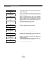
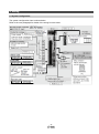
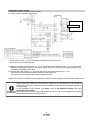
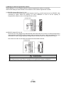
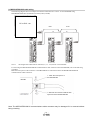
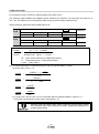
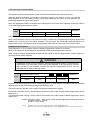
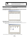
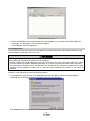
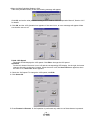
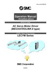
Doc. no. LEC-OM07503
(Simplified edition)
PRODUCT NAME
AC Servo Motor Driver
(MECHATROLINK-III type)
MODEL / Series / Product Number
LECYU Series
Contents
Introduction ................................................................................................. 6
1. Procedure before operation.................................................................... 7
1.1 Flow chart ........................................................................................................ 7
2. Wiring ....................................................................................................... 8
2.1 System configuration ..................................................................................... 8
2.2 Wiring for power supply ................................................................................. 9
2.3 Wiring for Safety cable .................................................................................. 11
2.4 Wiring for external regenerative resistor .................................................... 12
2.5 MECHATROLINK cable wiring ..................................................................... 13
3. Communications Setting ...................................................................... 14
4. Parameter setting (Driver side) ............................................................ 16
4.1 power supply specifications ........................................................................ 16
4.2 Overtravel ...................................................................................................... 16
4.3 Rotation Direction ......................................................................................... 17
4.4 Electronic Gear ............................................................................................. 18
4.4.1 List of the electronic gear setting for each actuator ..............................................19
4.5 Positioning Completed Width ...................................................................... 20
4.6 Regenerative Resistor .................................................................................. 20
5. Trial Operation (SigmaWin+) ................................................................ 21
5.1 Communications setting for PC .................................................................. 21
5.2 JOG Operation .............................................................................................. 23
5.3 Program JOG Operation............................................................................... 25
6. The recommended the parameter for each actuator........................... 28
6.1 The recommended value of the parameter [LEF] ....................................... 28
6.2 The recommended value of the parameter [LEJ] ....................................... 29
6.3 The recommended value of the parameter [LEY]....................................... 29
-2-
LECYU Series / Driver
Safety Instructions
These safety instructions are intended to prevent hazardous situations and/or equipment damage.
These instructions indicate the level of potential hazard with the labels of “Caution,” “Warning” or “Danger.”
They are all important notes for safety and must be followed in addition to International Standards (ISO/IEC),
Japan Industrial Standards (JIS)*1) and other safety regulations*2).
*1) ISO 4414: Pneumatic fluid power -- General rules relating to systems
ISO 4413: Hydraulic fluid power -- General rules relating to systems
IEC 60204-1: Safety of machinery -- Electrical equipment of machines (Part 1: General requirements)
ISO 10218-1992: Manipulating industrial robots -- Safety
JIS B 8370: General rules for pneumatic equipment.
JIS B 8361: General rules for hydraulic equipment.
JIS B 9960-1: Safety of machinery – Electrical equipment for machines. (Part 1: General requirements)
JIS B 8433-1993: Manipulating industrial robots - Safety. etc.
*2) Labor Safety and Sanitation Law, etc.
Caution
Caution indicates a hazard with a low level of risk which, if not avoided, could result in minor or
Warning
Warning indicates a hazard with a medium level of risk which, if not avoided, could result in death
Danger
Danger indicates a hazard with a high level of risk which, if not avoided, will result in death or
IMPORTANT
moderate injury.
or serious injury.
serious injury.
Indicates important information that should be memorized, as well as precautions, such as alarm
displays, that do not involve potential damage to equipment.
Warning
1. The compatibility of the product is the responsibility of the person who designs the equipment or
decides its specifications.
Since the product specified here is used under various operating conditions, its compatibility with specific
equipment must be decided by the person who designs the equipment or decides its specifications based
on necessary analysis and test results.
The expected performance and safety assurance of the equipment will be the responsibility of the person
who has determined its compatibility with the product.
This person should also continuously review all specifications of the product referring to its latest catalog
information, with a view to giving due consideration to any possibility of equipment failure when
configuring the equipment.
2. Only personnel with appropriate training should operate machinery and equipment.
The product specified here may become unsafe if handled incorrectly.
The assembly, operation and maintenance of machines or equipment including our products must be
performed by an operator who is appropriately trained and experienced.
3. Do not service or attempt to remove product and machinery/equipment until safety is confirmed.
The inspection and maintenance of machinery/equipment should only be performed after measures to
prevent falling or runaway of the driven objects have been confirmed.
When the product is to be removed, confirm that the safety measures as mentioned above are
implemented and the power from any appropriate source is cut, and read and understand the specific
product precautions of all relevant products carefully.
Before machinery/equipment is restarted, take measures to prevent unexpected operation and
malfunction.
4. Contact SMC beforehand and take special consideration of safety measures if the product is to
be used in any of the following conditions.
1) Conditions and environments outside of the given specifications, or use outdoors or in a place exposed
to direct sunlight.
2) Installation on equipment in conjunction with atomic energy, railways, air navigation, space, shipping,
vehicles, military, medical treatment, combustion and recreation, or equipment in contact with food and
beverages, emergency stop circuits, clutch and brake circuits in press applications, safety equipment or
other applications unsuitable for the standard specifications described in the product catalog.
-3-
3) An application which could have negative effects on people, property, or animals requiring special
safety analysis.
4) Use in an interlock circuit, which requires the provision of double interlock for possible failure by using
a mechanical protective function, and periodical checks to confirm proper operation.
Note that the
CAUTION level may lead to a serious consequence according to conditions. Please follow the
instructions of both levels because they are important to personnel safety.
-4-
LECYU Series / Driver
Safety Instructions
Caution
The product is provided for use in manufacturing industries.
The product herein described is basically provided for peaceful use in manufacturing industries.
If considering using the product in other industries, consult SMC beforehand and exchange specifications
or a contract if necessary.
If anything is unclear, contact your nearest sales branch.
Limited warranty and Disclaimer/Compliance Requirements
The product used is subject to the following “Limited warranty and Disclaimer” and “Compliance
Requirements”.
Read and accept them before using the product.
Limited warranty and Disclaimer
The warranty period of the product is 1 year in service or 1.5 years after the product is delivered.*3)
Also, the product may have specified durability, running distance or replacement parts. Please
consult your nearest sales branch.
For any failure or damage reported within the warranty period which is clearly our responsibility, a
replacement product or necessary parts will be provided.
This limited warranty applies only to our product independently, and not to any other damage
incurred due to the failure of the product.
Prior to using SMC products, please read and understand the warranty terms and disclaimers noted
in the specified catalog for the particular products.
*3) Vacuum pads are excluded from this 1 year warranty.
A vacuum pad is a consumable part, so it is warranted for a year after it is delivered.
Also, even within the warranty period, the wear of a product due to the use of the vacuum pad or failure
due to the deterioration of rubber material are not covered by the limited warranty.
Compliance Requirements
When the product is exported, strictly follow the laws required by the Ministry of Economy, Trade and
Industry (Foreign Exchange and Foreign Trade Control Law).
-5-
Introduction
It is recommended that the operator read the operation manual for LECYU prior to use.
For the handling and details of other equipment, please refer to the operation manual for used equipment.
Select ΣV as an object series when you use SigmaWin+.
Refer to the table for the following type when you select the model (parameter edit at offline etc.).
Driver type
MECHATROLINK-Ⅲ
SMC
LECYU2-**
Driver select
Sigma Win+
SGDV-****21* Y572AA
SMC
V5
V7
V8
V9
Motor select
Sigma Win+
SGDV-R90A21B
SGDV-1R6A21B
SGDV-2R8A21B
SGDV-5R5A21A
Please download setup software (SigmaWin+) via our website.
Refer to chapter 2.2 of operation manual for LECYU for method of installing setup software
(SigmaWin+).
-6-
1. Procedure before operation
1.1 Flow chart
Confirm that the cables to the driver and the actuator are
connected correctly.
Refer to [2. Wiring].
Wiring check
---
Surrounding
environment check
---
Check the surrounding environment (cable routing and
impurity such as wire off cuts or metallic dust) of the driver
and the servo motor.
Power-on of the power
supply
---
Follow the procedure shown in the "LECYU Operation
Manual" to supply power to the product. When the power
supply is turned on first, it is necessary to set up the
absolute encoder. (Only the absolute encoder) Refer to [2.
Wiring].
Communication setting
of MECHATROLINK
---
Set the MECHATROLINK communication.
Refer to [3. Communication setting].
Set the parameters.
Refer to [4. Parameter setting (Driver side)].
Parameter setting
---
Test operation
(JOG operation)
---
Use the test operation mode (JOG operation) at the
slowest speed and check whether the servo motor rotates.
Refer to [6. Trial Operation (SigmaWin+)].
Gain tuning
---
Operation with a vibration might be done according to the
condition.In that case, adjust gain.
Refer to the operation manual for LECYU.
Actual operation
---
Stop
---
Check if the cables to the driver and actuator are
connected correctly.
* "Return to home position" and "Positioning operation" etc.
are possible by the instruction from PLC.
Refer to the manual of the PLC for details.
Stop command to stop the operation.
-7-
2. Wiring
2.1 System configuration
The system configuration chart is shown below.
Refer to the next paragraph for details of the wiring for each cable.
-8-
2.2 Wiring for power supply
Connect the actuator and driver power supply.
(1) Power supply is AC200V three phase
Driver
Motor cable
[2]
Actuator
[1]
Encoder cable
∗ For the LECYU2-V5, V7, V8, terminals B2 and B3 are not short-circuited.
Do not short-circuit these terminals.
[1] Main circuit power input terminals, L1, L2, L3 and Control power input terminals, L1, L2: Connect the
200VAC external power supply to the power supply. Refer to the power supply specification for the
size of the acceptable electric wire.
[2] Connect the motor cable (U, V, W) to the servomotor connection terminals (U, V, W).
Connect the motor ground terminal to the driver ground terminal.
Connect the encoder cable to the encoder cable connector.
*Please connect lock connection terminal (B) with the DC24V power supply for the motor cable with the lock.
When starting the machine for the first time, setting up and reinitialization of the absolute
encoder are necessary. When the absolute encoder is used as the incremental encoder, it
is unnecessary.
In the SigmaWin+ main window, click Setup, point to Set Absolute Encoder and click
Reset Absolute Encoder.
The absolute encoder can only be set up while the servo is off. Turn the power back on after
the encoder has been successfully set up.
-9-
(2) Power supply is AC200V single phase
Driver
∗ For the LECYU2-V5, V7, V8, terminals B2 and B3 are not short-circuited.
Do not short-circuit these terminals.
[1] Main circuit power input terminals, L1, L2 and Control power input terminals, L1, L2: Connect the
200VAC external power supply to the power supply. Refer to the power supply specification for the
size of the acceptable electric wire.
[2] Connect the motor cable (U, V, W) to the servomotor connection terminals (U, V, W).
Connect the motor ground terminal to the driver ground terminal.
Connect the encoder cable to the encoder cable connector.
**Please connect lock connection terminal (B) with the DC24V power supply for the motor cable with the
lock.
When starting the machine for the first time, setting up and reinitialization of the absolute
encoder are necessary. When the absolute encoder is used as the incremental encoder, it is
unnecessary.
In the SigmaWin+ main window, click Setup, point to Set Absolute Encoder and click
Reset Absolute Encoder.
The absolute encoder can only be set up while the servo is off. Turn the power back on after
the encoder has been successfully set up.
- 10 -
2.3 Wiring for Safety cable
(1) Connection Example for input signals
The input signals must be redundant.
DRIVER
For safety function signal connections, the input signal is the 0 V common and
the output signal is the source output.
When using the safety function, a safety function device must be connected
and the wiring that is necessary to activate the safety function must be done to
turn ON the servomotor power. When not using the safety function, use the
DRIVER with the Safety Jumper Connector (provided as an accessory)
inserted into the CN8.
(2) Connection Example for output signals
EDM1 output signal is used for source circuit. It is not able to use the sink output.
DRIVER
PLC
- 11 -
2.4 Wiring for external regenerative resistor
Please prepare it in your company when the external regenerative resistor is necessary.
Refer to the catalog of each actuator for the selection of the external regenerative resistor.
(1) DRIVERs: Model LECYU2-V5, V7, V8
and B2 terminals on the DRIVER. After
Connect an external Regenerative resistor between the B1/
connecting a option, select the capacity. For more information on how to set the capacity of
Regenerative resistors, refer to 4.6 Regenerative resistor.
Enlarged View
(2) DRIVER: Model LECYU2-V9
Disconnect the wiring between the DRIVER’s B2 and B3 terminals and connect an external Regenerative
and B2 terminals. After connecting the option, select the capacity. For more
resistor between the B1/
information on how to set the capacity of Regenerative resistors, refer to 4.6 Regenerative resistor.
Note: Be sure to take out the lead wire between the B2 and B3 terminals.
Enlarged View
WARNING
Be sure to connect the regenerative resistor correctly. Do not short-circuit between B1/ ⊕ and
B2. Doing so may result in fire or damage to the regenerative resistor or DRIVER.
- 12 -
2.5 MECHATROLINK cable wiring
The following diagram shows an example of connections between a PC or PLC...etc and a DRIVER using
MECHATROLINK-III communications cables (CN6A, CN6B).
PC or PLC...etc.
Note 1
Note 1.
Note 1
The length of the cable between stations (L1, L2 ... Ln) must be 75 m maximum.
For removing the MECHATROLINK-III communications cable connectors from the DRIVER, refer to the following
procedure.
Slide the lock injector of the connector to the DRIVER side to unlock and remove the MECHATROLINK-III
communications cable connectors.
1. Slide the lock injector to
the DRIVER side.
DRIVER
2. Remove the connector while the lock
injector is slid to the DRIVER side.
Note: The MECHATROLINK-III communications cable connector may be damaged if it is removed without
being unlocking.
- 13 -
3. Communications Setting
The DIP switch S3 is used to make the settings for MECHATROLINK-III communications.
The station address is set using the rotary switches S1 and S2.
(1) Settings of the Rotary Switches S1 and S2
Set the station address using the rotary switches S1 and S2.
Station Address
00H to 02H: Disabled
(Do not use these addresses.)
03H (Factory setting)
04H
・
・
・
EFH
F0H to FFH: Disabled
(Do not use these addresses.)
S1
0
S2
0 to 2
0
0
3
4
E
F
F
0 to F
(2) Settings of the DIP Switch S3
The following table shows the settings of the DIP switch (S3).
Switch No.
Pins 1 and 2
Function
Sets the number of transmission
bytes.
Setting
Description
1
2
Number of transmission
bytes
OFF
OFF
16 byte
ON
OFF
32 byte
OFF
ON
48 byte
ON
ON
Reserved. (Do not change.)
Factory setting
1: OFF
2: ON
Pin 3
Reserved. (Do not change.)
OFF
Pin 4
Reserved. (Do not change.)
OFF
• When using the MECHATROLINK-III standard servo profile, set the number of transmission
bytes to either 32 or 48.
• When using the MECHATROLINK-II-compatible profile, set the number of transmission
bytes to either 16 or 32.
• Turn the power OFF and then ON again to enable the new settings.
- 14 -
Ex) When you connect three station
PC or PLC...etc.
No.1
No.2
No.3
Setting the Station Address
03H
04H
S1
0
0
S2
3
4
05H
0
5
Station Address
No.1
No.
2
No.
3
- 15 -
4. Parameter setting (Driver side)
The setting is a necessary parameter. Please optionally set it. Please refer to "LECYU manual" for a detailed
parameter.
Setup software (SigmaWin+) is necessary for the setting of the parameter.
※1 Please download setup software via our website.
※2 Prepare USB cable (LEC-JZ-CVUSB) separately.
4.1 power supply specifications
When using the DRIVER with single-phase, 200 V power input, set parameter Pn00B.2 to 1.
Parameter
Pn00B
n.口0口口
Enables use of three-phase power supply for
[Factory setting] three-phase DRIVER.
n.口1口口
When
Enabled
Classification
After restart
Setup
Meaning
Enables use of single-phase power supply for
three-phase DRIVER.
4.2 Overtravel
For machines that move using linear motion, connect limit switches to P-OT and N-OT of CN1 as shown
below to prevent machine damage. To prevent a contact fault or disconnection from causing accidents, make
sure that the limit switches are normally closed.
DRIVER
Parameters Pn50A and Pn50B can be set to enable or disable the overtravel function.
If the overtravel function is not used, no wiring for overtravel input signals will be required.
Parameter
Pn50A
When
Enabled
Classification
After restart
Setup
n.1口口口
Inputs the Forward Run Prohibited (P-OT) signal
[Factory setting] from CN1-7.
n.8口口口
Pn50B
Meaning
Disables the Forward Run Prohibited (P-OT)
signal. Allows constant forward rotation.
n.口口口2
Inputs the Reverse Run Prohibited (N-OT) signal
[Factory setting] from CN1-8.
n.口口口8
Disables the Reverse Run Prohibited (N-OT)
signal. Allows constant reverse rotation.
*P-OT and N-OT of the factory setting are effective.
Please set it invalidly when you use neither P-OT nor N-OT. (Please set to parameter Pn50A=n.8 口口口 and
Pn50B=n. 口口口 8. )
- 16 -
4.3 Rotation Direction
The servomotor rotation direction can be reversed with parameter Pn000.0 without changing the
polarity of the speed/position reference. This causes the rotation direction of the servomotor to
change, but the polarity of the signal, such as encoder output pulses, output from the DRIVER does
not change.
- 17 -
4.4 Electronic Gear
It is necessary to set it on the PLC side according to the kind of PLC.
The electronic gear enables the workpiece travel distance per reference unit input from the host PC or
PLC...etc. The minimum unit of the position data moving a load is called a reference unit.
Set the electronic gear ratio using Pn20E and Pn210.
Electronic Gear Ratio (Numerator)
Pn20E
Position
Setting Range
Setting Unit
Factory Setting
When Enabled
1 to 1073741824
1
4
After restart
Electronic Gear Ratio (Denominator)
Pn210
Position
Setting Range
Setting Unit
Factory Setting
When Enabled
1 to 1073741824
1
1
After restart
・Pn20E
Classification
Setup
Classification
Setup
M × P × (1/1000)
=
・Pn210
Actuator lead
L[mm] × (n1/n2)
M :Servo motor resolution is 1048576 [Pulse/rev]
P :Travel amount per 1 command pulse [μm]
n1/n2 :Pulley ratio *1
Ex.) To Travel amount per 1 command pulse (P=1μm) by actuator lead (L = 6mm)
and pulley ratio (n1/n2 = 1/1)
Pn20E
Pn210
=
Pn20E
Pn210
=
Pn20E
Pn210
=
Pn20E
Pn210
=
1
1048576 × 1 × 1000
6 × 1/1
1048576
6
× 1000
1048576
6000
65536
375
*1 For pulley ratio, refer to Lead of “LECYU Operation Manual (Simplified Edition)”,section 4.4.1.
The actuator not described for pulley ratio is calculated by “1/1”.
Electronic gear ratio setting range: 0.001 ≤ Electronic gear ratio (B/A) ≤ 4000
If the electronic gear ratio is outside this range, a parameter setting error 1
(A.040) will be output.
- 18 -
4.4.1 List of the electronic gear setting for each actuator
The recommended the electronic gear for each actuator.
Please change the electronic gear by use of the customer.
Series
LEY25/LEYG25
LEY25D/LEYG25D
LEY32/LEYG32
LEY63D
LEY
LEY32D/LEYG32D
LEY63
LEFS25
LEFS32
LEF
LEFS40
LEFB25
LEFB32
LEFB40
LEJB40
LEJB63
LEJ
LEJS40
LEJS63
Lead
Lead
symbol
(Including
pulley
ratio)
A
B
C
A
B
C
A
B
C
A
B
C
12
6
3
20
10
5
16
8
4
20
10
5
5(2.86)
L
(Pulley ratio
4/7)
H
A
B
H
A
B
H
A
B
S
S
S
T
T
H
A
B
H
A
B
20
12
6
24
16
8
30
20
10
Pn20E
131072
750
375
375
1250
625
625
1000
500
250
1250
625
625
229376
625
65536
131072
65536
131072
65536
65536
54
27
42
24
16
8
30
20
10
Pn210
1250
750
375
1500
1000
500
1875
1250
625
3375
131072
65536
3375
2625
1500
1000
500
1875
1250
625
*The travel distance of the actuator per 1 pulse should be 1 [μm/pulse].
- 19 -
4.5 Positioning Completed Width
This signal indicates that servomotor movement has been completed during position control.
When the difference between the number of references output by the host PC or PLC...etc and the
travel distance of the servomotor (position error) drops below the set value in the parameter, the
positioning completion signal will be output.
Note: Use parameter Pn50E.0 to allocate the /COIN signal for use. Refer to the operation manual for LECYU
3.3.2 Output Signal Allocations for details.
Positioning Completed Width
Pn522
Position
Setting Range
Setting Unit
Factory Setting
When Enabled
0 to 1073741824
1 reference unit
7
Immediately
Classification
Setup
The positioning completed width setting has no effect on final positioning accuracy.
Note: If the parameter is set to a value that is too large, a positioning completed signal might be output if the
position error is low during a low speed operation. This will cause the positioning completed signal to be
output continuously. If this signal is output unexpectedly, reduce the set value until it is no longer output.
4.6 Regenerative Resistor
Please prepare it in your company when the external regenerative resistor is necessary.
Refer to the catalog of each actuator for the selection of the external regenerative resistor.
When using an external Regenerative resistor, set the Pn600 so that the Regenerative resistor capacity is
equivalent to the resistor capacity.
WARNING
If parameter Pn600 is set to 0 while an external Regenerative resistor is connected, the
regenerative over- load alarm (A.320) may not be detected. If the regenerative overload
alarm (A.320) is not detected correctly, the external Regenerative resistor may be
damaged and an injury or fire may result.
Regenerative resistor Capacity
Pn600
Speed
Position
Torque
Setting Range
Unit
Factory Setting
When Enabled
0 to DRIVER
capacity
10 W
0
Immediately
Classification
Setup
Be sure to set the Regenerative resistor capacity (Pn600) to a value that is in accordance with the allowable
capacity of the actual external Regenerative resistor being used.
The setting will vary with the cooling method of external Regenerative resistor:
For natural convection cooling: Set the value to a maximum 20% of the actually installed regenerative option
capacity (W).
For forced convection cooling: Set the value to a maximum 50% of the actually installed regenerative option
capacity (W).
Example: Set 20 W (100 W × 20%) for the 100-W external Regenerative resistor with natural
convection cooling method:
Pn600 = 2 (unit: 10 W)
Note 1.
2.
If Pn600 is not set to the optimum value, alarm A.320 will occur.
When set to the factory setting (Pn600 = 0), the DRIVER’s built-in option has been used.
- 20 -
•
• When the external Regenerative resistors for power are used at the rated load
ratio, the resistor temperature increases to between 200 °C and 300 °C. The
resistors must be used at or below the rated values. Check with the
manufacturer for the resistor’s load characteristics.
For safety, use the external Regenerative resistors with thermoswitches.
5. Trial Operation (SigmaWin+)
The procedure of the test driving with setup software (SigmaWin+) is shown below. When use the setup
software (SigmaWin+), order USB cable (LEC-JZ-CVUSB) separately.
5.1 Communications setting for PC
When SigmaWin+ is initially started, the Connect dialog box appears. Enter the settings for communications
between SigmaWin+ and the DRIVER by means of a communication port.
Select the method to set up the DRIVER: online or offline. Online is the default setting.
<When Offline is selected>
Online: Select when setting up or tuning the servo drive with the DRIVER connected
Offline: Select when editing parameters or checking screens for tracing or mechanical analysis without the
DRIVER connected
Select the DRIVER series and click Starting. The SigmaWin+ main window will appear.
- 21 -
<When Online is selected>
Enter the necessary settings for communication setup.
1. Click Search.
2. Select DRIVER series and make the settings required. Click Search.
After the DRIVERs have been successfully connected to SigmaWin+, a list of the connected DRIVERs
will appear on the screen.
- 22 -
DRIVER Selection Box
3. Select the DRIVER to be connected and then click Connect, or just double-click the DRIVER to be
connected. The SigmaWin+ main window will appear.
Click Cancel to close the dialog box.
5.2 JOG Operation
This function turns the motor at the set JOG speed. The rotational direction and the speed setting can be
verified without connecting a PC or PLC etc.
WARNING
Performing JOG operation while the motor is running is dangerous. Be sure to check the user's manual
before executing. Pay particular attention to the following.
• Check the safety of the area adjoining the drive unit. The motor runs at the JOG speed, while the Forward
or Reverse button is pressed. Make sure that there is no danger in running the motor before execution.
• The Forward Run Prohibit (P-OT) and Reverse Run Prohibit (N-OT) signals are disabled during JOG
operation. During operation, make sure to verify the actual operation and position of the motor or
machine.
Perform a JOG operation using the following procedure.
1. In the SigmaWin+ main window, click Test Run, and then click Jog. A warning message appears
reminding you of the dangers that are possible when using this operation.
Click Cancel to return to the main window without performing JOG operation.
- 23 -
<When the Write Prohibited Setting is ON>
If the write prohibited setting is ON, the following message will appear.
Click OK, and set the write prohibited setting to OFF. Refer to “LECYU Operation Manual”, Section 4.4.5
for details.
2. Click OK, and the JOG Operation box appears. If the servo is on, an error message will appear. Make
sure that the servo is off.
Pn304: JOG Speed
Parameter Pn304 displays the JOG speed. Click Edit to change the JOG speed.
Operation
On the left, shows if the servo is on or off and the corresponding LED display. On the right, the button
changes according to the servo’s status. When the servo is off, the Servo ON button appears; when
the servo is on, Servo OFF button appears.
3. Check the JOG speed. To change the JOG speed, click Edit.
4. Click Servo ON.
5. Press Forward or Reverse. A JOG operation is performed only while one of these buttons is pressed.
- 24 -
5.3 Program JOG Operation
This function allows automatic operation determined by the preset pattern of operation.
WARNING
Using the program JOG operation function while the motor is running is dangerous. Be sure to check the
user’s manual before using this function. Pay particular attention to the following items.
• Check the safety of the area adjoining the drive unit. The motor actually runs based on a preset pattern
when this function is used. Make sure that there is no danger in running the motor before actually using it.
• Confirm the position of the machine. Reset the machine position using the Origin Return function before
using the program JOG function.
CAUTION
Two methods are available to stop program JOG operation while the motor is running, and the motor will
stop according to the method selected. Make sure to select the best method for the situation.
• If the Servo OFF button is used, the motor stops according to the stopping method after servo off specified
by the parameters.
• If the Cancel button is used, the motor coasts to a stop and then enters a zero clamp state.
Note: The Cancel button may not be used with some DRIVERs.
To perform the JOG operation for a particular pattern, use the following procedure.
1. In the SigmaWin+ main window, click Test Run and then click Program JOG Operation. A warning
message appears, reminding you of the possible dangers.
Click Cancel to return to the main window without performing program JOG operation.
2. Click OK, and the Running Condition Setting box appears.
- 25 -
3. Set the running conditions and click Apply. The graph for the operation pattern is displayed.
4. Click Run and the Program JOG Operation box appears.
5. Click Servo ON and Execute. The program JOG operation starts.
- 26 -
- 27 -
6. The recommended the parameter for each actuator
The recommended the parameter for each actuator. Please change the parameter values by use of the
customer. A mechanical resonance may occur depending on the configuration or the mounting
orientation of the transferred object. Please change the parameter in the initial setting.
Refer to “LECYU Operation Manual”, Section 4 and Section 5 and Section 10 for details.
6.1 The recommended value of the parameter [LEF]
LEFS25
Series
Parameter
Servomotor Rotation
Direction can
Tuning-less Function
Related Switch
Electronic Gear Ratio
(Numerator) *1
Electronic Gear Ratio
(Denominator) *1
LEFS32
H
A
B
H
A
B
H
A
B
Lead
Initial
Para.
value
No
20
12
6
24
16
8
30
20
10
500
1875
1250
625
Recommended value
Pn000
0000
0001
(+:Counter motors side )
Pn170
1401
1401
Pn20E
4
65536
Pn210
1
1250
750
375
1500
LEFS25(L,R)
Series
Parameter
Servomotor Rotation
Direction can
Tuning-less Function
Related Switch
Electronic Gear Ratio
(Numerator) *1
Electronic Gear Ratio
(Denominator) *1
Lead symbol
Para.
No
Lead
Initial
value
Parameter
Servomotor Rotation
Direction can
Tuning-less Function
Related Switch
Electronic Gear Ratio
(Numerator) *1
Electronic Gear Ratio
(Denominator) *1
1000
LEFS32(L,R)
LEFS40(L,R)
H
A
B
H
A
B
H
A
B
20
12
6
24
16
8
30
20
10
1875
1250
625
Recommended value
Pn000
0000
0000
(+:Counter motors side)
Pn170
1401
1401
Pn20E
4
65536
Pn210
1
1250
750
LEFB25
Series
LEFS40
Lead symbol
375
LEFB25U
1500
1000
LEFB32
500
LEFB32U
Lead symbol
S
Lead
Para.
Initial
value
No
54
LEFB40
LEFB40U
0001
(+:Counter
motors side )
0000
(+:Counter
motors side)
Recommended value
0001
(+:Counter
motors side )
0000
(+:Counter
motors side)
0001
(+:Counter
motors side )
0000
(+:Counter
motors side)
Pn000
0000
Pn170
1401
Pn20E
4
65536
Pn210
1
3375
1401
2301
: Different from the initial value.
*1:The minimum unit of the travel distance of the actuator should be 1 [μm]. It is necessary to set it on the
PLC side according to the kind of PLC.
- 28 -
6.2 The recommended value of the parameter [LEJ]
Series
Parameter
Servomotor Rotation
Direction can
Tuning-less Function
Related Switch
Electronic Gear Ratio
(Numerator) *1
Electronic Gear Ratio
(Denominator) *1
Lead symbol
Lead
Para.
Initial
value
No
Pn000
0000
Pn170
1401
Pn20E
4
Pn210
1
LEJS40
A
16
H
24
B
8
LEJS63
A
20
H
30
LEJB40
B
10
LEJB63
T
27
42
Recommended value
0001
(+:Counter motors side )
0000
(+:Counter motors side)
1401
65536
1500
1000
500
1875
1250
625
131072
65536
3375
2625
: Different from the initial value.
*1:The minimum unit of the travel distance of the actuator should be 1 [μm]. It is necessary to set it on the
PLC side according to the kind of PLC.
6.3 The recommended value of the parameter [LEY]
LEY25/ LEYG25
Series
Parameter
Servomotor Rotation
Direction can
Tuning-less Function
Related Switch
Electronic Gear Ratio
(Numerator) *1
Electronic Gear Ratio
(Denominator) *1
LEY25D/ LEYG25D
LEY32/LEYG32
Lead symbol
A
B
C
A
B
C
A
B
C
A
B
C
Lead
Para.
Initial
value
No
12
6
3
12
6
3
20
10
5
16
8
4
Pn000
0000
Pn170
1401
Pn20E
4
Pn210
1
Recommended value
0000
(+:Counter
motors side)
0000
(+:Counter
motors side)
0001
(+:Counter
motors side )
Parameter
Servomotor Rotation
Direction can
Tuning-less Function
Related Switch
Electronic Gear Ratio
(Numerator) *1
Electronic Gear Ratio
(Denominator) *1
65536
750
Lead symbol
Lead
(Including pulley
ratio)
Para.
Initial
value
No
Pn000
0000
Pn170
1401
Pn20E
4
Pn210
1
0001
(+:Counter
motors side )
1401
131072
375
375
65536
750
375
131072
65536
125
0
375
131072
62
5
625
LEY63
Series
LEY32D/ LEYG32D
A
B
65536
100
0
500
250
LEY63D
C
L
A
B
C
20
10
5
5(2.86)
20
10
5
(Pulley
ratio 4/7)
Recommended value
0000
(+:Counter motors side)
0001
(+:Counter motors side )
1401
65536
1250
625
131072
229376
625
625
65536
1250
131072
625
625
: Different from the initial value.
*1:The minimum unit of the travel distance of the actuator should be 1 [μm]. It is necessary to set it on the
PLC side according to the kind of PLC.
- 29 -
Revision history
No.LEC-OM07501
Feb./2014 1st printing
No.LEC-OM07502
Jul./2014 2nd printing
No.LEC-OM07503
Apr./2015 3rd printing
4-14-1, Sotokanda, Chiyoda-ku, Tokyo 101-0021 JAPAN
Tel: + 81 3 5207 8249 Fax: +81 3 5298 5362
URL http://www.smcworld.com
Note: Specifications are subject to change without prior notice and any obligation on the part of the manufacturer.
© 2015 SMC Corporation All Rights Reserved
- 30 -