1
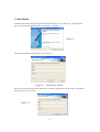
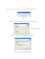
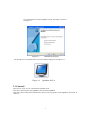
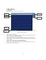
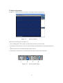
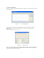
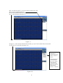
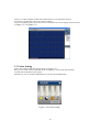
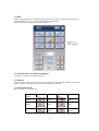
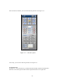
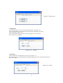
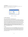
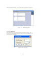
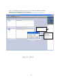
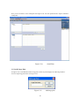
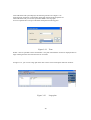
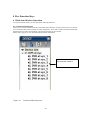
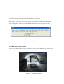
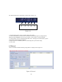
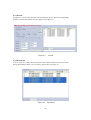
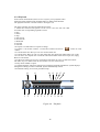
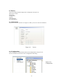
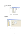
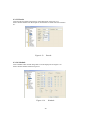
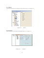
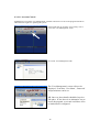
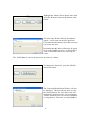
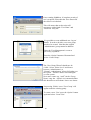
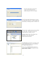
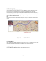
SightBoss System User’s Manual
For use with the DVR365 DVR range
Network all your DVR365 units using the
SightBoss software
Version 3.0
Table of Contents
Page
Welcome
1. Features
SightBoss Explained
2. Installation
2.1 Environment
2.2 Installation
2.3 Uninstall
3. Main Window
3.1 Interface
3.2 Device Operation
3.2.1 Device Management
3.3 Colour Setting
3.4 PTZ
3.4.1 Direction Keys & 3D positioning key
3.4.2 Speed
3.4.3 Zoom/Focus/Iris
3.4.4 Auto Scan
3.4.5 Pattern
3.4.6 Preset
3.4.7 Auto Tour
3.5 Plan Management
3.5.1 Add Small Plan
3.5.2 Add Large Plan
4. Five Function Keys
4.1 Realtime Monitor Operation
4.1.1 Network Connection
4.1.2 Switch Preview/Monitor Mode
4.1.3 Realtime Monitor Window
4.2 Record
4.2.1 Search
4.2.2 Download
4.2.3 Playback
2
4
4
4
4
4
5
7
8
8
9
10
12
13
13
13
13
14
15
15
16
16
17
19
22
22
22
23
23
24
25
25
26
4.3 Device
4.3.1 Information
4.3.2 Configuration
4.3.2.1 Device Configuration
4.3.2.2 General
4.3.2.3 Encode
4.3.2.4 Schedule
4.3.2.5 RS232
4.3.2.6 Network
4.3.2.7 Alarm
4.3.2.8 Detect Setup
4.3.2.9 PTZ
4.3.2.10 Tools
4.3.3 Upgrade
4.3.4 Control Record
4.3.4.1 User Management
4.3.4.1.1 Account Control
4.4 System
4.4.1 Local Record
4.4.2 Local User Manager
4.4.3 System Log
4.4.4 About
4.5 E-map
4.5.1 Add an E-map
4.5.2 Remove an E-map
4.5.3 Modify an E-map
4.5.4 E-map Operation
4.5.5 Device Operation
4.5.6 Open Device
4.5.7 Multiple E-maps Operation
4.5.8 Multiple Sub E-maps Setup
5. Appendix
3
27
27
27
28
28
29
29
30
30
31
31
32
33
33
34
35
36
40
40
40
41
41
42
42
43
43
43
44
44
44
45
46
Welcome
Thank you for using SightBoss.
This operating manual is designed to be a reference tool for the installation and
operation of your system.
Here you can find information about this multiple-client features and functions.
1. Features
Multiple-client has the following features:
Manages a number of DVR devices
Supports multiple-device connections, real-time surveillance and playback
Allows device management, log review and user management
Controls PTZs and alarm devices,
Video record controls
SightBoss Explained
The SightBoss software not only controls the individual DVR setup and control features,
but also allows a user to control a number of DVR365s remotely as a monitoring tool. The
software allows the building of a monitoring plan covering one or more DVRs, so that
timed displays from individual channels across the DVRs are sequenced within a 24 hour
period. No need now to log onto different static IP addresses for the individual DVRs as
these can be entered into the plan allowing instant monitoring facilities.
2. Installation
2.1 Environment
We recommend the following configuration:
Hardware
CPU P4 2.0GHz
Display card: must support hardware zoom - such as ATI, TNT2 PRO. We recommend ATI9800 or
above dual channel. 128M/128bit
Network card: 100M
Software:
For client end we recommend Windows 2000 or Windows XP.
4
2.2 Installation
Install from the CD by running Setup then “Install Client Software”located on the “Client Software
Tab”or by launching SightBoss-Setup.exe manually. See figure 2-1.
Figure 2-1
Figure 2-1 Start
Then the InstallAware Wizard displays as per Figure 2-2.
Figure 2-2
InstallAware Wizard
Enter your Name and Company name followed by 16 character alpha/numeric Serial Number. The number
will be found on CD cover sleeve.
Figure 2-3
5
If the Serial Number entered is not valid, the following error message will be displayed as per Fig. 2.4
Figure 2-4
Click next to continue or select folder name. The following image will appear. See Figure 2-5.
Figure 2-5 Select Folder
Click next to continue, the following image will be displayed. See Figure 2-6.
Figure 2-6 Ready to Install SightBoss program
6
Now click Install to start the SightBoss install. The image is shown as
in Figure 2-7.
Figure 2-7
Installation progress
You should now see multiple-client icon on the desktop displayed. See Figure 2-9.
Figure 2-9
SightBoss 2007-A
2.3 Uninstall
There are two ways for you to uninstall the multiple-client.
Click Start, then Program, then SightBoss, then Uninstall SightBoss.
Click Start, then Control Panel and then select add or remove programs. Select SightBoss, then click on
‘Remove’.
7
3 Main Window
3.1 Interface
Multiple-client main window is shown as in Figure 3-1.
Section 5
Section 1
Section 2
Section 6
Section 3
Section 4
Figure 3-1 Main window
There are a total of six sections:
Section 1: There are five function keys: monitor, record, device, system and e-map. Please
refer to chapter four for detailed information.
Section 2: This is where you view video channels.
Section 3: This is where you select display mode. System supports the following display
modes: Full-screen /Single window/Four-window/Six-window/Eight-window/Nine-window/
sixteen-window.
Section 4: This is where you view current help information.
Section 5: This is where data flux and CPU status are displayed.
Section 6: There are four function menus: PTZ/Colour setting/Device/Plan. Please refer to
chapter three for detailed information.
8
3.2 Device Operation
In Figure 3-1, click device button in section 6, the image is shown as in Figure 3-3.
Figure 3-3
Device interface
There are four function keys. See Figure 3-4.
1. Device Management: This is where you add a physical DVR to your device list.
2. Connect/Disconnect: Select a device or camera and then click this button to connect/disconnect from
it.
3. Reboot: Select a device and then click this button to reboot.
4. Talk: Select a connected device and then click this button to begin remote audio talk.
1
2
Figure 3-4
3
4
Device function keys
9
3.2.1 Device Management
In Figure 3-3, click device management button (Button 1 in Figure 3-4), the following image is shown
below. See Figure 3-5.
Figure 3-5
Device management
Click add button, you can see the following display for you to add a new device. See Figure 3-6.
Please input device name (such as DVR), IP address, user name, password and port number
(Default 37777)
Click save button and then click close to exit.
Figure 3-6
Add new device
NOTE: The username and password entered here are those configured on the actual DVR that you are
connecting to. When populating this list with multiple DVRs it is common practice to have different
usernames and passwords for various DVRs.
10
After you add a new device, you can see below the device list, that
there is a newly added DVR device.
You should see the font below the interface that advises when this
device is disconnected. See Figure 3-7.
Figure 3-7
In Figure 3-7, click connection/disconnection button, you can see the red font below the interface
says this device is connected. See Figure 3-8.
You can double
click here to
connect/disconnect
either a camera or
device.
Also the red cross
icon beneath the
Device or camera
name indicates
connection status.
Red Cross present =
disconnected.
Absent = connected.
Figure 3-8
11
Click on a window and then double click channel name on your right hand, and you
will see the corresponding video in the selected window.
You can click display icons below the screen to switch between various display modes (section 3
in Figure 3-1). See Figure 3-9 .
Figure 3-9
3.3 Colour Setting
Click colour setting button, the image is shown in Figure 3-10.
Here you can select a channel and then adjust its brightness, contrast, hue and saturation.
(Current channel border becomes green).
Alternatively you can click the default button to use the system default setup.
Figure 3-10 Colour setting
12
3.4 PTZ
Before any PTZ operation is attempted, please make sure you have set the correct PTZ protocol
parameters (Refer to 4.3.2 .9 Device-Pan/Tilt/Zoom) in the DVR.
Click PTZ button, the image is shown as in Figure 3-11.
Figure 3-11
PTZ interface
3.4.1 Direction key and 3D positioning key
In Figure 3-11, there are eight direction keys.
3.4.2 Speed
System supports eight-level speeds. You can select from the dropdown list. Speed 2 is faster than
speed 1. NOTE: This depends on the options available on your PTZ.
3.4.3 Zoom/Focus/Iris
Here is a sheet for your reference.
Name
Function
Key
Function
Function
Key
Function
Zoom
Near
Far
Focus
Near
Far
Iris
Close
Open
13
Then click Advance button, you can see the following interface. See Figure 3-12.
Figure 3-12 Advance option
Click setup, you can see the following interface. See Figure 3-13.
3.4.4 Auto scan
In Figure 3-13, move the camera to you desired location and then click the left limit button.
Then move the camera again and then click the right limit button to set a right limit.
14
Figure 3-13 Auto-scan
3.4.5 Pattern
Click Pattern button, you can see the following interface .see Figure 3-14.
You can input pattern value and then click start button to begin PTZ movement.
System goes back to figure 3-12.
After you finished camera operation, please go to figure 3-14 to click stop.
Now you have set one Pattern.
Figure 3-14
Pattern
3.4.6 Preset
Click Preset button, the image below is shown. See Figure 3-15.
Move the camera to your desired location and then input preset value. Click add button and you
have set one Preset.
Figure 3-15 Preset
15
3.4.7 Auto tour
Click auto tour button and the image below is shown. See Figure 3-16.
You can input auto tour value and preset value. Click add button, you have added one preset in
the tour.
Repeat the above procedure to add more presets in one tour.
Figure 3-16 Auto tour
3.5 Plan Management
What is a Plan and What is Plan Management ?
An operator may wish to view a series of cameras from several DVRs over a period of
time, he may want the display of particular cameras viewed to change periodically without
human intervention. He can choose a selection of cameras from the available DVRs and
specify a period for which each should be displayed, this selection can be saved in a list
called a ‘plan’.The sightBOSS software can maintain 2 such lists, a master (called ‘Large’
plan) and a secondary (called ‘Small’plan).The ‘Small’plan defines the cameras selected
and defines how long each camera should be displayed for, these display times being
expressed in seconds.The ‘Large’plan defines an activation time, for one or more of the
‘Small’plans. Each of these plans can be saved with a descriptive name for easy
identification and sightBOSS provides a means of adding, editing and deleting these plans
under it’s ‘Plan Management’facility.
Example:
A council may define a master ‘Large’plan called Daytime becoming active at 09:00 am
that uses smaller plans to display cameras around the market square and shopping areas.
This may be followed by a second ‘Large’plan called Evening becoming active at 10:00
pm which calls smaller plans to display cameras around the pubs & clubs. The choice of
cameras within any of the small plans may be changed at any time independently of the
large plans that use them.
16
Click plan management button, you can see the following interface. See Figure 3-17.
Figure 3-17
Plan management
3.5.1 Add Small Plan
Click add button and system displays the following interface. See Figure 3-18.
You can input small plan name and window amount (select from the dropdown list)
Click OK to add one small plan.
Figure 3-18 Small plan
17
Click + icon before the channel name and you can view the newly added four channels.
Click device channel and then select channel number.
System displays a dialogue box for you to set the interval parameter. See Figure 3-19.
Step 2
Double click channel
name
Step 3
System displays
interface. Input
interval value here and
then click OK
Figure 3-19
Interval
18
Now you can see there is a new small plan. See Figure 3-20. You can repeat the above steps to add more
small plans.
Figure 3-20
Small Plan
3.5.2 Add Large Plan
In Figure 3-20, click add button below large plan column. System displays the following interface.
You can input large plan name. See Figure 3-21.
Figure 3-21
19
Add large plan
Click add button and system displays the following interface. See Figure 3-22.
Input start time and select corresponding small plan name from the dropdown list.
Click OK button and you will see system has added a new large plan.
You can repeat the above steps to add other small plans into this big plan.
Figure 3-22
Time
NOTE: Time is specified as hours and minutes. The plan will match the current PC displayed time to
begin running and does not reference time set in a DVR.
In Figure 3-23, you can see a large plan front door consists of two small plans: Entrance and Exit.
Figure 3-23
20
Large plan
After you create a large plan, you can click the plan name and then click start to enable a large plan.
See Figure 3-24.
Figure 3-24 Enable Large Plan
21
4 Five Function Keys
4.1 Real-time Monitor Operation
In real-time monitor mode, you can operate the following functions.
4.1.1 Network Connection
Select a device name and then click the connect/disconnect button to connect current device to network.
You will see the little red cross below the name, disappears. Now click a window and then double click
channel name to see the corresponding video displayed in the current window.
Please refer to Figure 4-1 for connection/disconnection information.
Disconnected channels
Figure 4-1
Connection/Disconnection
22
4.1.2 Switch between Preview Mode and Real-time Monitor Mode
You can click the preview button to view total channels in one window.
System displays the following interface. See Figure 4-2.
Right click one video in the preview mode you can view current channel real-time monitor data.
Right click again system goes back to multiple-screen preview mode.
You can highlight the check box to disable this interface when you enter the option next time.
Figure 4-2
Prompt
4.1.3 Real-time monitor window
In the video window interface, you can see the device name in the top left-hand corner. There are five
function keys also situated in the top right-hand corner. See Figure 4-3.
Figure 4-3
Real-time monitor
23
For detailed function key information, please refer to Figure 4-4.
1
2
3
4
5
Figure 4-4
1: Switch display mode: resize or switch to full screen mode.
2: Local record. When you click local record button, the system begins recording and this
button becomes highlighted. You can go to system -.local record to set video file path.
3: Capture picture. You can snapshoot important video. All images are memorized in system
client folder \download\picture (default).
4: Audio :Turn on or off audio.(It has no relationship with system audio setup )
5: Close video.
4.2 Record
Click record button and the following image below is displayed. See Figure 4-5.
Figure 4-5 Record
24
4.2.1 Search
In Figure 4-5 you can select file type, start time/end time, device name and corresponding
channel, click the search button and view display. See Figure 4-6.
Figure 4-6
Search
4.2.2 Download
You can select one or more files in the search result column to download to your local PC.
During download procedure, you can refer to progress bar. See Figure 4-7.
Figure 4-7
Download
Figure 4-7 Download
25
4.2.3 Playback
In the search result interface, there are two ways for you to playback video.
Select file name and then click playback button or double click filename.
The playback interface is shown as below. See Figure 4-8.
The player interface provides the following functions:
1: Frame rate. There are nine options: 1f / 2f / 3f / 6f / 12f / 25f / 50f / 75f / 100f
You must click corresponding segment to select.
2: Play
3: Pause
4: Stop
5: Start record
6: Previous file
7: Backward
8: Forward
9: Next file
10: Capture: Use this feature to capture an image..
11: Sound: + is to increase volume, - is to decrease volume. Click icon “
”to turn on or off
volume.
12: Current frame rate: Here you can view current frame rate.
13: Current status: Here you can view play status bar, play mode and volume status (on or off).
14: Convert to AVI: System can convert the video file of suffix name such as mp4, Dav, mpeg,
H264 to AVI format.
15: Full-screen: There are two ways: click full-screen button to review in full-screen mode.
The other way is to double click current window to review in full-screen.
16: Play mode: shuffle or repeat.
17: Change language: The player supports two languages: English and Chinese. System displays
dialogue box asking to restart. Click OK, System automatically restarts.
18: Parameter setting. You can set parameter setup.
12
1
2
13
3
14 15 16 17 18
4
5
6
7
8
9 10 11
Figure 4-8 Playback
26
4.3 Device
Click device button and the image below is displayed. See Figure 4-9.
There are five items:
Information
Configuration
Upgrade
Control Record
User Management
4.3.1 Information
Information interface is shown as in Figure 4-9. Here you can view device information.
Figure 4-9
Device
4.3.2 Configuration
Click configuration and the interface below will be displayed as in Figure 4-10.
You can see there are two items: device configuration and setting.
Figure 4-10
Configuration
27
4.3.2.1 Device configuration
Click device configuration, you can see system hardware and software version information. See
Figure 4-11.
Figure 4-11
Device Configuration
4.3.2.2 General
Click general button to set device time, time format etc. See Figure 4-12.
Figure 4-12
General setup
28
4.3.2.3 Encode
Click Encode Set and the image below will be displayed. See Figure 4-13.
Select channel number from the dropdown list and then set frame rate and resolution
etc.
Figure 4-13
Encode
4.3.2.4 Schedule
Click schedule button and the image below will be displayed. See Figure 4-14.
Select channel number and then set period.
Figure 4-14
29
Schedule
4.3.2.5 RS232
Click RS232 button and you can set data bit, stop bit, baud rate, parity etc. see Figure 4-15.
Figure 4-15
RS232
4.3.2.6 Network
Click network button to set IP address, Subnet Mask, Gateway etc. see Figure 4-16.
Figure 4-16
Network
30
4.3.2.7 Alarm
Click alarm button and the image below will be displayed. See Figure 4-17.
Set alarm channel, alarm type etc.
.
Figure 4-17
Alarm in
4.3.2.8 Detect setup
Click detect button and system will display following interface. See Figure 4-18.
Set motion detection type, motion detection region, sensitivity etc.
Figure 4-18
Detection setup
In Figure 4-18, click select button and the image below will be displayed. See Figure 4-19
You can drag your mouse in the screen to set motion detection section. The blue zone is the motion
detection section.
31
Figure 4-19
Motion Detection Region
4.3.2.9 PTZ
Click the pan/tilt/zoom button and the following image will be displayed. See Figure 4-20.
Set PTZ information such as protocol, address etc.
Figure 4-20
PTZ
32
4.3.2.10 Tools
Click Tools button and the following image will be displayed. See Figure 4-21.
You can view system directory and load or save system configuration.
If you click the save configuration button you can save current system setup into a file (extension name
CFG) or you can click load configuration button to load a configuration file.
Figure 4-21
Tools
4.3.3 Upgrade
Click upgrade button and the following image will be displayed. See Figure 4-22.
Figure 4-22
Upgrade
33
Click BIOS upgrade tool and system displays the following interface. See Figure 4-23.
You can select upgrade file and then click send button to begin upgrade.
Please note that opening the file button is invalid if there is no connected device.
Figure 4-23
Open file.
4.3.4 Control Record
Click Control Record button and the system displays the following interface. See Figure 4-24.
Select a device and then select corresponding record type.
Figure 4-24
Record management
34
4.3.4.1 User Management
Click User Management button and system displays the following interface. You can add /delete a user
(group) or modify its corresponding password. See Figure 4-25.
Figure 4-25
User management
SightBoss allows access of multiple DVRs but can also be used from different locations
accessing one or more DVRs. It is therefore important to note the following rules:
1. It is important that an administrator changes the admin password to a unique name
which is best set at 6 characters in lower case.
2. When allocating certain rights of access these appertain to the Group and not to the
person. Set up a Group with necessary rights and then allocate users who can use this
Group.
3. Whilst it is possible to have several administrators (providing different passwords are
allocated) it is recommended that for ease of operation that only one admin user is
allocated. Users can be setup under a User Group and have rights allocated with the overall
control by the administrator.
The ways in which these Groups and Users are setup are explained below.
35
4.3.4.1.1 Account Control
SightBoss has a powerful ‘User Management’tool that controls user access to the program and allows
individual users rights for operating the system.
From initial start up, click the ‘User Config’icon to
access the ‘User Management’menu.
Now click ‘User Management’link.
The ‘User Management’screen will now be
displayed. From here ‘User Name’,‘Password’
and permissions can be set.
NB. Once set, these details should be kept in a
safe place. If lost, there is no alternative way to
access the program, as a result it will have to be
re-loaded and re-configured.
36
Highlight the ‘admin’link as shown above and
press the ‘Rename’button at the bottom of the
screen.
The following ‘Rename Wizard’should now
appear. A new name can now be input here.
Convention dictates that no more than six lower
case letters are used.
Remember that this name will need to be typed
in for each SightBoss session. A short name is
easier to remember and leaves less scope for
errors.
The ‘Finish Button’can now be pressed to save the new ‘Name’.
To change the ‘Password’,press the ‘Modify
Password’button.
The ‘Password Modification Wizard’will now
be displayed. The user will now have to enter
the ‘Old Password’,the ‘New Password’and
confirm the ‘New Password’. By pressing the
‘Finish’button the user will now be committed
to using the new ‘Password’to start SightBoss.
37
On re-starting SightBoss, if complete security of
use is required, ensure that the ‘Save Password’
check box is un-checked.
This will ensure that each session will
commence with a blank ‘User Name’and
‘Password’entry bar.
It is possible to create additional user ‘log on’
details. In order to do this, a new user group
needs to be created. Note that the original
‘Administrator’group cannot be added to.
Enter the ‘User Management’screen as
previously explained.
Press the ‘Option’button as illustrated and
select ‘Create Group’.
The ‘New Group Wizard’should now be
visible. Select ‘Select Level’and choose
between ‘Administrator’or
‘Normal’.‘Administrator’allows full rights over
the system. ‘Normal’allows restricted rights
over the system.
Now enter a name (eg. “staff”) in the ‘Group
Name’entry bar. Again it is recommended that
this should be no more than 6 lower case letters.
On pressing ‘Finish’a new ‘User Group’will
appear under the existing group.
To create a new ‘User’press the ‘Option’button
again and select ‘Create User’
38
Select the appropriate ‘User Group’
via the ‘New Account Wizard’
window and press ‘Next’to confirm.
Now fill in the blank fields with the ‘Account’
user name and ‘Password’. Finally confirm the
password by re-entering it in the ‘Confirm’bar.
The new ‘User’“jsmith can now be seen below
the “staff”link. This process can now be
implemented for a number of users.
Remember that it is the ‘User Group’(not
individual ‘Users’) that can have
rights/permissions defined.
By highlighting a particular ‘User Group’,that
group’s rights/permissions can be defined by
checking the appropriate box.
If the ‘User’is highlighted then access to a
particular DVR can also be controlled via the
upper ‘Device’window.
39
4.4 System
Click system button and the following will be displayed.
4.4.1 Local record
Local record interface is shown below. You can modify record video backup path and file size.
See Figure 4-26
Figure 4-26
System
4.4.2 Local User Manager
Click Local User Manager and you can see the following interface. See Figure 4-27.
Local user manager consists of four items: monitor/net playback/local control/remote control/user
right.
You can select a function by highlighting appropriate checkbox.
Figure 4-27
Local User Manager
40
4.4.3 System log
Click system log button to view system log information. See Figure 4-28.
Figure 4-28
Log
4.4.4 About
Click the About button and the image below is displayed. See Figure 4-29.
Here you can view system version information.
Figure 4-29
About
41
4.5 E-map
Click e-map button and you will see the following interface. There are four sections: Preview,
Map, E-map and Functions.
The Functions buttons are : edit, map, picture ,picture edit and save. See Figure 4-31.
Please note you need to highlight edit check box to enable map, picture and picture edit
functions.
Preview
Map List
E-map
Functions
Figure 4-31
E-map Main Window
4.5.1 Add an E-map
Click picture edit button in Figure 4-31, and system displays background picture manager interface.
See Figure 4-32. You can click add button to add a picture into the map.
Figure 4-32
Background Picture Manager
42
Click add button and you can see Figure 4-33.
Click browser button to select picture and then input picture name and description.
Click OK to finish operation. Repeat the procedure to add more pictures.
Finally, you can go to map list section to check newly added maps.
Figure 4-33
Add an E-map
4.5.2 Remove an E-map
In background picture manager interface (Figure 4-32), select picture to remove and then click remove
button. System displays a dialogue box asking for your confirmation. Click Yes button to
remove current E-map.
4.5.3 Modify an E-map
In background picture manager interface (Figure 4-32), select picture to be modified and then click
modify button. System displays E-map property dialogue box (just the same as Figure 4-33).
Now you can modify E-map property.
Tip: In background picture manager interface (Figure 4-32) you can double click a picture name to
modify its property.
4.5.4 E-map Operation
Click picture button, left click picture name and then drag it into E-map section.
You can see an interface as in Figure 4-34.
Figure 4-34
E-map
43
4.5.5 Device Operation
You can find a newly added E-map in the map list.
Click map button and then select the map you want to add device by double clicking device name.
Now there is a device icon on the map. You can drag it to your desired location on the map.
You will see there is a red icon in the preview section to indicate current position. See Figure 4-35.
Please note when you continuously add devices, you need to select and place each one as system places
them initially at the same point.
System only displays devices used in the map so that you can easily identify devices on the map or not.
Click save button to finish the operation.
Tip:
In the map preview section, drag rectangle cursor (green rectangle) to change map content in Emap
section.
Figure 4-35
Add New Device
4.5.6 Open Device
After you add a device, double click camera icon in the map list. You can enable device to go to realtime monitor mode. Note that inactivated devices display a red cross below the name.
4.5.7 Multiple E-maps Operation
You can add multiple sub-maps in one map. Please follow previous steps.
44
4.5.8 Multiple Sub E-maps Setup
Follow the procedures below
Open one map such as map1.
Click picture button and drag map 2 to anywhere in map1.
Click map button and click map 2 to open current map
Double click device name to add device to map 2.
You can view newly added E-map and device list in the map list section.
Click save button. Now you have added one sub-map and its device.
You can repeat this procedure to add more maps.
Tip:
You can use one device in several maps.
45
5 Appendix
AudioRecord.dll
AudioRecordEx.dll
decode.dll
render.dll
dhdvr.dll
dhnetsdk.dll
dhplay.dll
DhStreamParser.dll
dllh264.dll
ParaTimer.dll
HWPlay.dll
dhtmman32.dll
dspdec.out
Password.dll
Audio interface library
Audio interface enhanced library
Decode library
Play library
Network ground library
Network interface layer
Soft decoder library
Data stream analyzer
H.264 decoder library
Timer library
Decode card interface library
Decode card driver library
Decode card DSP library
Character string encryption library
Note:
Slight differences may be found in user interface.
All the designs and software here are subject to change without prior written
notice.
46