1
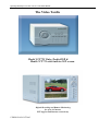
Operating Manual for CCT721 & CCT722 Video Tardis Manual
The Video Tardis
Model CCT722 Video Tardis DVR &
Model CCT721 with built-in LCD screen
Digital Recording and Remote Monitoring
for up to 4 Cameras.
PTZ support and Internet connectivity.
VERSION 005/OCT2005
Operating Manual for CCT721 & CCT722 Video Tardis Manual
CONTENTS
Page number
1.
2.
3.
4.
5.
6.
7.
8.
9.
10.
11.
12.
13.
14.
15.
16.
17.
18.
19.
20.
21.
22.
23.
24.
25.
26.
27.
28.
Contents
Operating Precautions/Accessories Checklist
Specification
Features
Recording Reference Table
Hard Disk installation
CCT722 Front Panel Layout
CCT721 Front Panel Layout
Key Functions Table
Rear panel layout
Alarm and RS485 connections
System operation
System Menu Structure
Recording Operation/PTZ Operation
Network Connection Operation
Front Panel Operation Guide
Menu Option Schedule
Record/Playback Operation
Pan-Tilt menu Guide
Menu Operation/Record Search/Information
Menu Operation/System Setting
Menu Operation/Admin Setting
Menu Operation/Backup
Playback of CDROM
Client Software
Web Software
Frequently Asked Questions (troubleshooting)
Appendix A
Recording Times
2
2
3
4
5
6
7
8
9
10
11
12
14
15
16
17
22
23
27
29
30
31
34
35
36
37
39
47
48
Operating Manual for CCT721 & CCT722 Video Tardis Manual
OPERATING PRECAUTIONS
All the safety and operating instructions should be read before the DVRs is operated.
All the safety and operating instructions should be retained for future reference.
Ensure all operating instruction and warning notes are complied with at all times.
Do not use strong or abrasive detergents when cleaning the DVRs.
There are no user-serviceable parts inside. Please contact a qualified engineer for servicing
Do not expose the DVRs to water or moisture and do not try to operate it in wet areas.
Please make sure that both ends of the power lead are plugged in.
Do not drop foreign objects through the DVRs case or expose it to moisture.
Do not attempt to disassemble the DVRs, other than to fit the Hard Drives.
Contact a qualified engineer if the following situation happens:
The power lead or plug is damaged.
o The DVRs has been exposed to rain or water.
o The DVRs does not operate normally by following the operating instructions.
o The DVRs is dropped or its cover is damaged.
When replacement parts are required, make sure that the service engineer has used replacement
parts specified by System Q Ltd or that these parts have the same characteristics as the original
ones. Unauthorized substitutions may result in fire, electric shock or other hazards.
Use only with a mounting accessory recommended by System Q Ltd.
Never push objects of any kind into the case of the DVR365 as they may touch dangerous voltage
points or short out parts that could result in a fire or electric shock.
If an outside cable system is connected to the DVR365, be sure that the cable system is grounded so
as to provide some protection against voltage surges and built-in static charges. It is recommended
that this unit is connected to a power surge protection unit.
All normal precautions to avoid component damage due to electrostatic discharge should be taken
during installation and operation.
To prevent electric shock, do not remove screws or the unit’s cover with the power connected.
Do not cover the ventilation fan
Accessories Check List
One Power Cable
One HDD Data Cable
One Standard Cat 5 Network Patch Lead
One Packet Of Installation Fixings
One CD For Installation of the Client software and the Player
One User Manual
One Crossover Lead (Yellow)
3
Operating Manual for CCT721 & CCT722 Video Tardis Manual
SPECIFICATION
Parameter
Processor
Operation system
Model
Video input
Video output
Audio input
Audio output
Video display
Video standard
System resource
Image resolution
Motion detection
Video compression
Audio compression
Image compression rate
Video recording speed
Image quality
Hard disk
HDD space used
Alarm input
Alarm output
Alarm relay
MODEM connection
Network connection
Pan-tilt control
Power
Power consumption
Working temperature
Working humidity
Barometric pressure
Size
Weight
4 Channel
PNX1302/200MH
Real-time operation system PSOS
CCT722 CCT721 DVR – The Video Tardis
4 Channel (NTSC/PAL) BNC 1.0VP- P 75
1 Channel PAL/NTSC BNC 1.0VP- P 75 video signal
1 Channel 200-1000mv10K (RCA)
1 Channel 2000mv 1K (RCA)
1,4, 5 windows display
NTSC 525 line, 60f/s
PAL 625 line, 50f/s
Non real-time recording and simultaneous network operation,
independent local playback
Real-time monitor 704×576, playback 352×288,
Area setting: 192 detection areas on the screen; detection sense setting:
3 levels detection sense for each area
MPEG-4 CBR (fixed frame rate); MPEG-4 VBR (variable frame rate)
ADPCM
352×288CIF format
Total resources 25frames for PAL mode, 30 frames for NTSC mode
6 levels selectable
Internally equipped with 1 IDE ports, supporting 2 drives
Audio 14.4Mbyte/hour Video 60-460Mbyte/hour
4 channel voltage alarm input
15V D. C. Needed for the alarm
input
3 channels output, output in open/close contact or controllable
12V output
30VDC 1A, 125VAC 0.5A relay output
Not Available
RJ45 10M/100M Ethernet connection
RS485, RS232
220+25%V 50+2% HZ
60W
10 deg. C ~ 55deg. C
10
90
86kpa 106kpa
200 (breadth) x275 (depth) x130mm (height)
5KG (not including hdd)
4
Operating Manual for CCT721 & CCT722 Video Tardis Manual
FEATURES
Real-time Monitor
·Analogue Video output port, standard 1volt peak to peak to a CCTV monitor
·Single window/4 windows monitor
Compression Method
·Multiple video compression modes: MPEG4 fixed frame MPEG4 adjustable frame
·Single channel or 4 split audio/video real-time recording or multi-channel non-real time audio/video recording
Storage
·1-2 IDE-connected large capacity HDD inside
·Alternate HDD working method, reduce the power consumption and heat emission
·Overwrite and Stop modes, user selectable for when the HDD is full.
Back-up
·USB port to backup records
·Download the files on DVR to local PC via network/RJ45 connection
Play and record
·Supports multiplex operation: live monitor, record, file search for downloading, one channel playback and remote transmission
simultaneously
·Multiple recording mode: manual, timed, alarm and motion detection,
·Playback: one window playback or one window playback with four small windows simultaneously on screen; real time monitoring
during local playback
·Fast search for timed recording and alarm/event recording
·Multiple playback modes: fast play, pause, x1/2,x1/3, x1/4 slow play and frame-by-frame playback
Alarm relay
·4 channel external alarm input, video loss alarm and motion detection alarm
·Multi channel relay switch alarm output allowing external device switching
·Limited protection circuit for the Alarm input and output thus reducing damage through incorrect operation
Pan-tilt Control
·Supports the pan-tilt decoder using RS485 communication
·Integrated multiple decoding protocols so as to control various pan-tilt cameras
Communication connection port
·15-pin port for alarm input and pan-tilt camera control
·RS232 port for the connection with keyboard for central control and matrix control
·Standard Ethernet port for remote connection and control via a network
Network operation
·Remote real-time monitor via network
·Pan-tilt control
·Record search and real-time playback (playback quality depends on network condition), backup downloading through network
·System setting modification and system software upgrading
·Remote alarm process and system log review
·Embedded TCP/IP protocol and operation system supports Web server, allowing web access
·Administration mode: Multi- level access from a normal user to administrator over a network; secure password mode assures the legal
user’s login
5
Operating Manual for CCT721 & CCT722 Video Tardis Manual
RECORDING REFERENCE TABLE
The recording length of the DVRs Tardis is dependant on the capacity of the installed HDD’s and the selected image level.
(6 being the highest quality setting)
The following storage time is based on the average used HDD space for single channel real-time recording @ 25f/s.
Coding
Image
level
Resolution
Frames
TV Frames
Maximum
data flux
Fixed Baud
1
352*288
25
330 lines
128 Kb/S
Average
used HDD
space/hour
40Mb
2
352*288
25
330 lines
256 Kb/S
80Mb
3
352*288
25
330 lines
384 Kb/S
120Mb
4
352*288
25
330 lines
512 Kb/S
160Mb
5
352*288
25
330 lines
768 Kb/S
240Mb
6
352*288
25
330 lines
1 Mb/S
320Mb
Rate
Fixed Baud
Rate
Fixed Baud
Rate
Fixed Baud
Rate
Fixed Baud
Rate
Fixed Baud
Rate
Note: Audio recording is not included.
6
Operating Manual for CCT721 & CCT722 Video Tardis Manual
HARD DISK INSTALLATION
If there is no hard disk fitted when initially purchased, check the hard disk equipment for the first installation. It is possible to fit
a maximum of 2 x 400GB capacity hard discs inside the machine. The user can decide the number of hard disks according to
required image quality, recording time and HDD capacity.
Installation Steps
Remove the fixing screws
securing the top cover.
Install the first HD (Master).
Replace the front cover.
Dismantle the front cover.
Fix the HD bracket.
Dismantle the HD Bracket.
Install the second HD (Slave).
Replace the top cover and fixing screws.
7
Operating Manual for CCT721 & CCT722 Video Tardis Manual
CCT722 FRONT PANEL LAYOUT
Key Functions
1.
Up Direction Arrow
2.
Left Direction Arrow
3.
Escape/Cancel Key
4.
Down Arrow Direction
5.
Enter
6.
Right Direction Arrow
7.
Go to Previous section (during playback) (Password Number 1)
8.
Record
9.
Slow Play (Password Number 2)
10. Function Key
11. Play/Pause (Password Number 3)
12. Fast Forward (during playback) (Password Number 4)
13. Go to next section (during playback) (Password Number 5)
14. Power On/Off
15. Channel Record Indicator
16. Channel Record Indicator
17. Channel Record Indicator
18. Channel Record Indicator
19. Power Indicator
NOTE: Password Numeric Keys are used for entering the two levels of passwords.
8
Operating Manual for CCT721 & CCT722 Video Tardis Manual
CCT721 FRONT PANEL LAYOUT
2
1
3
4
5
6
7
8
9
10
10
11
12
13
14
Channel
Record
Indicators
Key Functions
1. Power On/Off
2. Function Key
3. Record
4. Up Direction Arrow
5. Left Direction Arrow
6. Escape/Cancel Key
7. Enter
8. Right Direction Arrow
9. Down Arrow Direction
10. Go to Previous section (during playback) (Password Number 1)
11. Slow Play (Password Number 2)
12. Play/Pause (Password Number 3)
13. Fast Forward (during playback) (Password Number 4)
14. Go to next section (during playback) (Password Number 5)
NOTE: Password Numeric Keys are used for entering the two levels of passwords.
9
Operating Manual for CCT721 & CCT722 Video Tardis Manual
Key Functions
ORDER
14,19
15, 16
17, 18
KEY NAME
FUNCTION
Power switch
and indicator
light
POWER
Recording
light
RED
LED
Indication light, red light is ON
If the light is ON it means that channel is recording
2, 6
Left and right
For left/right control and menus, shifting level1and level2
in the menu; pan-tilt control Left and Right, when
monitoring audio/video, change between channel 3 and
channel 4
1, 4
Up and down
Up or Down control; change setup; change number; pantilt control; when monitoring audio/video, change
between channel 1 and channel 2
3
Cancel
5
Enter
ESC
ENTER
10
Function
assistant
FN
8
REC
7
9
11
12
13
REC
Play last
section
Slow play
Play/pause
REMARK
Power switch Power off by pressing this key and
holding for 4 seconds
/
Fast play
Play next
section
Cancel
Press during playback to return to real-time monitor
Enter
Enter main menu
In the state of monitoring this toggles between single/four
windows
Press the key to display the menu of the pan-tilt and
camera lens control
Used for setting Motion Detection areas
During playback, displays the playback status bar
Manual start/stop recording Press the Rec key together
with number key, shadow numbers of the required
channel to start recording
Select single channel the selected channel will be in
real time recording select A=four channels real time
recording. Select multi-channels, the channels will be non
real time recording. These are as follows: 2 channels = 12
F/S, 3 channels = 8 F/S and 4 channels = 6 F/S **
Play the previously recorded file before the current file
3 levels of slow play speed (×1/2, ×1/5, ×1/25)
Play/pause
When in monitor, press it to enter recording search menu
different levels of fast forward play speed
Plays the recorded file after the current file
** F/S = frames per second
10
RECORD
1234
A
SELECT
CHANNEL
Operating Manual for CCT721 & CCT722 Video Tardis Manual
REAR PANEL LAYOUT
1.
2.
3.
4.
5.
6.
7.
8.
9.
10.
11.
12.
13.
14.
15.
16.
Alarms and RS485 connector (15 way ‘D’ type)
Cooling Fan
RS232 connector (9-way ‘D’type)
Modem telephone line connection (RJ12)
USB connector
RJ45 Network connector (Cat5)
Audio Output (BNC)
Audio Input (BNC)
Video Output (BNC)
Video Output (BNC)
Video Input (BNC)
Video Input (BNC)
Video Input (BNC)
Video Input (BNC)
Power Switch
Power Connector (3-pin IEC)
11
Operating Manual for CCT721 & CCT722 Video Tardis Manual
Alarm In/Out and RS485 Connections – (15-way ‘D’ type connector)
Pins 1, 2, 3, and 4 = alarm in 1-4
6, 7,8 =Alarm Output 1: 9, 10= Alarm output 2
15= +12 volt output
11= A line output RS485
12= B line output RS485
5 = Ground
13, 14 = Alarm Out 3 (normally open contact)
5 4 3
10 9 8
15 14 13
2 1
7 6
12 11
PTZ A line output RS485
PTZ B line output RS485
RS485 15 way 'D' type connector pin connections
The DVRs requires +12volts for its alarm input trigger. Pin 15 has a +12volt supply from the DVR. This will be enough to
operate approx 2 low current PIR devices (approx 50mA) as well as providing the switching voltage. If an external power supply
is used then remember to connect the 0volts to the DVRs Ground connection to provide a common reference. See examples 1
and 2 below:
Diagram of the Alarm Input
Example 1
Wiring diagram to trigger alarm using 12v supply from DVR
Alarm In
DVR
RS485
Pins 1-4
PIR
Pin 15 12v output
The above diagram shows a 12-volt alarm device being powered from the 15-way alarm connector on the rear of the DVR. The
Common terminal and the 12volt terminal are linked on the alarm device and the NO (Normally Open) contact is connected to
the required alarm input on the DVR. When the device is triggered 12volts is applied to the alarm input thus activating the DVR.
12
Operating Manual for CCT721 & CCT722 Video Tardis Manual
Example 2 Wiring diagram to trigger alarm using external 12v supply
DVR 12v
PIR
com
DVR
RS485
Pin 5 Ground
-0v
+12v
The above diagram shows a 12-volt alarm device being powered from an independent 12 volt power supply.
13
Operating Manual for CCT721 & CCT722 Video Tardis Manual
SYSTEM OPERATION
Before switching on the DVR make sure that the Hard Drives have been fitted as required. Refer to Installation for further
details.
Starting up the DVR
Plug in the power line; switch on the power button at the back of the recorder; at this point the power indicator light should be on. Now press
the front POWER key. The DVR will now start. If the settings are still at default the system will start recording automatically. The default
screen is four windows for the video output; press the Enter key to access the menu mode (the password will be required to enter the menus);
the corresponding channel indicator light will be on and the system works in the normal way.
Note: if the system stops at the starting image of HDD (Hard Disk Drive) detection, this means the HDD may not be installed correctly and
needs to be checked. See troubleshooting
Enter the set-up menu
Before you enter the menu, you must input the password. There are two levels of password—user password and advanced password
User password
444444
Press the "FAST PLAY" key 6 times (Numeric 4 Key)
The password is required every time the system set-up is entered. You are also limited to the changes you can make. You will not be allowed to
enter the system setting and admin setting.
Advanced password
555555
Press "GO TO NEXT SECTION" 6 times (Numeric 5 Key)
Note: For added security it is possible to change the default setting in admin setting. Refer to the Menu operation section.
Switching off the DVR
Press the POWER key on the front panel for 4 seconds to stop the DVR. Then switch off the power button at the rear to turn off the power.
Note: Always follow this procedure to shut down the DVR correctly and prevent data corruption. After pressing the POWER key the user
should wait for 5 seconds before trying to restart. Press the Power key in 5 seconds; the power goes into a state of protection, so the machine
can start again.
Power off recovery
If there is power loss during normal operation of the DVRs the recorder will preserve the recorded information and return to the previous state
and continue to work at the next restart. The state will be the same as it was before the power loss.
14
Operating Manual for CCT721 & CCT722 Video Tardis Manual
System menu structure
Record
List
SEARCH
Alarm
System information
Hdd information
INFORMATION
Version information
M
E
N
U
General
Timing
SYSTEM
SETTING
Image
Alarm
Control
Network
Motion detection
Password
Admin setting
Backup record
BACKUP
Others
Data delete
Default
Delete Backup
15
Logout
Operating Manual for CCT721 & CCT722 Video Tardis Manual
RECORDING OPERATION
The default recording mode after starting the DVR is 24 hours continuous recording. The recording options are selected by the user and are as
follows:
Timed recording
Enter the menu, now you can navigate to the Timing menu and set the time period for the recording.
Note that when you go into the timing menu you will see that Sunday is highlighted. To change each day you must go to the required day e.g.
Monday, highlight it, you will now notice that both Sunday and Monday are highlighted. To change the times for Monday you must go back to
Sunday and un-highlight it. Once you have changed Monday ensure that you save your settings before progressing to Tuesday. This process
must be done for each day. See details at Menu>System setting>Timing
Manual recording
Check the status of each channel in the recording menu. The highlighted channel is the recording channel.
For recording on the required channel, simply press the related number key and the REC key to highlight it. Then press Enter to begin the
recording.
To stop recording of a particular channel press the related number key.
Press Cancel or ESC to return. Note: The total recording resources is 25 frames for PAL mode, 30 frames for NTSC mode. This means that 1
channel will record at 25 frames, 2 channels at 12 frames, 3 channels at 8 frames and 4 channels at 6 frames.
Alarm Recording
Alarm recording allows you to increase the recording time of the DVR, as it will only start recording when the PIR etc picks up any movement.
Connect the alarm input device to the DVR according to the device connection i.e. Normally Open or Normally Closed detector. Select the
correct setting in the menu to start Alarm recording. See details at Menu>System setting>Alarm setting
Video Motion Detection (VMD) recording
Motion detection recording will also increase the recording time of the DVR, as it will only start the DVR recording when it picks up any
movement.
Points to consider when using Video Motion Detection: - It is important to remember that the DVR’s VMD circuits look for movement in the
camera’s picture, therefore if it is so dark that the camera cannot see any movement nor will the VMD circuits. However, if you were using
VMD in a darkened room as soon as the light is turned on, the VMD would cause the DVR to record, as the change in light would be seen as
movement. When you are using the VMD with external cameras, sudden changes of bright sunlight to cloud, may cause the VMD circuits to
trigger the DVR. With this in mind, outdoor use of VMD needs careful planning. In order for VMD to trigger the DVR you need to turn off
24h recording on the channel that requires VMD, ensuring that you do this for each day.
Now you can turn VMD on.
Set up the required times and required motion detection setting in the menu. See details at Menu>System setting>Motion Detection
Alarm output
The alarm output can be used to control an external device such as a buzzer to tell the user that the unit has been alarmed. Or it allows you to
remotely control a floodlight e.g. you could set the DVRs to turn a light on/off from the other side of the world. The alarm output is directly
proportional to the length of the recording time. After an alarm activation the unit will record for a user defined length of time and the output
relay will be latched for the same period of time. So if the recording is set at 30secs, the alarm output will be active for 30secs.
See details Menu>System setting>Alarm setting
Pan-tilt control operation
The Tardis range allows you to control Pan Tilt & Zoom Equipment. It is possible to control PTZ equipment from the DVR, using a Remote
Controlled Unit or you can operate it over a network connection.
Confirm the correct connection of the PTZ and the decoder, then set the correct decoder address.
You should enter the corresponding protocol of the PTZ equipment that you are using, from the Menu>System setting>Control menu.
Select :
CH
PROTOCOL
BAUD RATE
ADDR
SAVE
Channel number
Protocol type (note that the Tardis may utilise an alternative to the camera setting)
Baud rate speed
Address set in camera - usually set by dip switches
Save settings
Confirm the right connection of the camera's decoder A and B line and the DVR’s 15-pin port A and B line.
To have control over the PTZ equipment you need to ensure that the monitor is in single window mode (with the camera you require
displayed). You should now press the function1 key (Fn1). This gives you the control interface and if you press it again, the next menu will
pop up. Use the direction keys to move the PTZ equipment.
Please note – The PTZ protocols are of a limited range, therefore some functions that you can control on a PTZ keypad will not be available
using the DVR.
16
Operating Manual for CCT721 & CCT722 Video Tardis Manual
NETWORK CONNECTION OPERATION
The Tardis can be networked in three different ways; Direct connection, LAN connection or Internet connection.
1. DIRECT CONNECTION
It is possible to connect the DVR directly to a PC that has a Network Interface Card. It must be connected to a P.C using a
network crossover lead. This lead (NET992) can be supplied by SystemQ. You must give the DVR an Internet Protocol (IP)
address e.g 192.168.001.108. The subnet mask should be set to 255.255.255.0 Leave the Default Gateway blank. Power down
the Tardis to register the changes. Hold the front power button for 4 seconds, then switch off at the rear. Now power back on at
the rear of the DVR and then the front. Now set the PC with a unique I.P address in the same range as the DVR e.g
192.168.001.100 This can be usually be found by Entering main menu > system settings > networking. Set the subnet mask and
Gateway as above. Now load the DVR365 client and player software. The client software will require the DVR I.P adddress e.g
192.168.001.108, the subnet mask and Gateway as above.
2. LOCAL AREA NETWORK
You can connect the DVR to a Local Area Network (LAN) using the connection port on the rear of the DVR. You must use a
LAN cable as per the one supplied with the unit. You must give the DVR an Internet Protocol (IP) address. This must be unique
to your network but in the same range e.g 192.168.001.xxx. The subnet mask should be set to 255.255.255.0 The Default
Gateway should reflect the Router's IP address. Now set the PC with a unique I.P address in the same range as the DVR e.g
192.168.001.100 This can be usually be found by entering main menu > system settings > networking. Set the subnet mask and
Gateway as above. Now load the DVR365 client and player software. The client software will require the DVR I.P adddress e.g
192.168.001.108, the subnet mask and Gateway as above. In order to confirm the correct network connection between DVR and
computer, you can use the PING command that comes with Microsoft Windows systems. To access the PING command, follow
the sequence below: Start > Programs > Accessories > Command Prompt.
Once Command Prompt is open type (if 192.168.001.108 is the IP address of the DVR): PING 192.168.1.108
If it comes back and says ‘Request Timed Out’ then the two devices are not communicating/connected correctly. This could be
due to a bad or incorrect cable connection or the incorrect IP addresses. If it comes back and says ‘Reply from 192.168.001.108’
the two devices are connected correctly.
17
Operating Manual for CCT721 & CCT722 Video Tardis Manual
3. INTERNET CONNECTION
CHECKLIST – getting a Video Tardis on to the Internet
You need a broadband (ADSL) internet connection at the site where the DVR is to be installed.
The ADSL connection at the site where the DVR is installed must have a “STATIC IP address”.
(Note - you can request a static IP address from most Internet Service Providers (ISP’s), but they may charge a small fee for this.)
You will need a broadband router/modem at the DVR site. A good one is the Netgear DG834.
At the remote site where your computer will be located you will also need a broadband connection to ensure that you have a fast
connection to your DVR.
TIP - You can’t use a USB type modem connected to a stand alone PC to get the Tardis connected to the internet, you must get a routermodem, that allows multiple computers to share the broadband ADSL connection. USB modems rely on a computer’s operating system to drive
them and the DVR365 cannot do the same thing.
Once you have got your ADSL Internet connection with a static IP address at your DVR site, you can progress to installing the DVR.
If the site where the DVR is to be installed already has an ADSL Internet connection that is shared by one or more computers it is
likely to already have an ADSL modem/router of some description. If this is the case you will have to either configure the existing
modem/router or replace it with a new one. If it’s an existing installation, we strongly recommend you enlist the help of the person or
company that installed and configured it originally.
The rest of these instructions now refer to installation using the Netgear modem/router.
STEP 1 - GETTING THE ROUTER-MODEM CONNECTED TO THE INTERNET
If you have already done this and can already “surf the internet” you can skip this section and go straight on to step 2).
Your ISP should have given you all the information you need to get your modem and computers connected to the Internet. You should have the
following information;
login user name
password
static IP address
Connect your computer to the Netgear router using the blue STRAIGHT RJ45 cable supplied with the router. Next, you need to set up the
router to connect to the Internet. See the Netgear instructions of how to do this if you’re not sure, but the basic method is;
1.
Run Internet Explorer
2.
Type in the router’s address 192.168.000.1 (usual default for a Netgear)
3.
Type in the user name “admin”,
4.
Type in the password “password”
5.
You should now see the Netgear set-up page.
On this page navigate on the left-hand side to the
“WIZARD” and run this wizard to set up your
connection. When it asks you for the password etc
enter them. Obviously the Netgear modem needs to
be connected to your ADSL enabled telephone point.
When you have finished running the wizard you
should be able to test your connection and see live
Internet pages on your PC. If you cannot get the
Internet connection please run the wizard again and
check you have entered your user name and password
correctly. If you still have a problem at this stage you
MUST CONTACT your ISP.
TIP- if you cannot get your computer to connect to
the Netgear device, check that your computer is in the
same IP address range as the Netgear. This can be found by navigating from My Computer > Control Panel > Network Setting >TCP/IP >
Properties. If your computer is set up correctly in the same range as the Netgear router it will look like the picture on the right.
18
Operating Manual for CCT721 & CCT722 Video Tardis Manual
The Address 192.168.000.XXX means it’s in the same range as other devices that share the same common address 192.168.000. With just the
last 3 digits distinguishing between the various devices. For most networks - DO NOT CHANGE the subnet mask and leave it as
255.255.255.000
Once connected to the Internet you now need to set up the router so that you can connect to it and the DVR from anywhere in the world over
the Internet.
STEP 2 – SETTING UP YOUR STATIC IP ADDRESS IN THE ROUTER.
In the router navigate to the “Basic Settings” screen and click on “static IP address”.
Next enter the STATIC IP address given to you by your ISP, look at the following picture as an example, obviously the IP address in the
picture is an example you must enter your own here. The IP address you enter is the STATIC ADDRESS GIVEN TO YOU BY YOUR ISP.
Once you have entered this, please click the “apply” button at the bottom of the screen to update the router.
Once you have set up your router to work with a static IP address anyone who types this address into their web browser will be re-directed to
your router from anywhere in the world. The next task is to make the router “route” this request to the DVR.
19
Operating Manual for CCT721 & CCT722 Video Tardis Manual
STEP 3 – MAKE THE ROUTER “ROUTE” EXTERNAL CONNECTIONS TO THE DVR
There are a few ways to do this but we will show you the quickest and most reliable.
The Netgear router can be set up to forward all external connections to a particular IP
address (equipment) on your local area network, in this case this is the Tardis. The
method we are going to show you uses the DMZ feature of the Netgear router. Some
other routers have this feature so you will have to “tweak” and apply these notes to
your router if it’s a different model.
Open the Netgear’s menu marked WAN
Click default DMZ server,
Now enter the IP address of the Tardis - by default this may be 192.168.000.111 or possibly 192.168.1.111. Whatever IP address
you enter here is the IP address you MUST enter into the DVR. The Netgear router will send all external connections to this IP
address.
TIP – On a Netgear router the IP address of the DMZ server may appear greyed out, but you will be able to enter and amend the last 3 digits
of the IP address. If your local area network is not in the range 192.168.000.xxx, you will need to set up the Netgear router to the appropriate
range in its LAN settings screen.
Once you have set up the router to use a DMZ server and set up the DMZ’s IP address you can move on to setting up the DVR.
STEP 4 – SETTING UP THE DVR
The DVR needs to be connected into the same network as the Netgear router or directly to the router itself. To connect into the network or
directly to the router, use the “straight” grey RJ45 cable supplied with DVR. (Note when you are connecting the DVR directly to a computer
with no router you need a “crossover cable”. We can supply these as order code: NET992).
In the DVR you need to set up its IP address to be the same address as you set the DMZ server to be in the Netgear router. In this example,
both the DVR’s IP address and the DMZ server’s need to be set up to be 192.168.000.111. Also, you will set up the DVR’s “gateway” to be
the Static IP address of the router this means that it accesses the Internet through this “gateway”. In this example the DVR’s gateway will be
82.10.189.10
To get into the DVR menu press “enter” followed by the password “888888” if it’s still the default password
Now navigate to System Settings>Network
In System Setting enter the details as follows:
NETWORK
IP
SUBNETMASK
GATEWAY
SERVERPORT
TCP PORT
MONITOR
PLAYBACK
SAVE
192.168.000.111
255.255.255.000
82.10.189.001
00080
37777
TCP
TCP
CANCEL
Remember:
IP address = whatever you set the DMZ server to in the router
GATEWAY = the router’s IP address, i.e. your static IP address supplied by your ISP.
SUBNETMASK is that of your local area network = Leave at 255.255.255.000
TIP- we recommend you do not change the subnet mask, as this is the default setting for most networks.
20
Operating Manual for CCT721 & CCT722 Video Tardis Manual
After you have changed and saved the network settings in the DVR (such as the IP address) you MUST reboot the DVR for these changes to
take effect. Obviously please make sure you save the settings before you reboot!!
Once rebooted, and if the DVR is connected to the Netgear router you will need to test it from another broadband connection to make sure it is
working correctly.
Whilst we can help with the DVR settings, it is the ISP's responsibility to advise on the setup of your ADSL connection.
TOP TIP – You could use all the same settings in this example but CHANGE the static IP address 82.10.189.001 for the one given to you by
your ISP and use all the other IP addresses, as above. For example if your ISP has given you a static IP address of 212.123.67.98 wherever the
address “82.10.189.001” appears in the above example, replace it by 212.123.67.98 but use all the other settings as stated.
21
Operating Manual for CCT721 & CCT722 Video Tardis Manual
Front panel and remote controller operation
Operation menu introduction *The Flashing item is the currently selected one*
Menu items changing and setting
Operation
step
Enter main
menu and
level 1
submenu
Button-pressing
order
Instruction
1 Confirm Enter
During real-time monitor, press to bring up the
password , then either press the numeric key 4
six times for User password or press the
numeric key 5 six times for the Advanced
password. The menu should now be accessed.
2 Direction (Cursor
or direction
arrows)
Press to move and select the available options
3 Confirm Enter
Enter the selected level 1 submenu
4 Direction (Cursor
or direction arrows)
Press to move and select the level 2 submenu
item required
5 Confirm Enter
Enter the selected level 2 submenu
1 Direction (Right
Cursor or direction
arrow)
Select the option to be changed, when the
heading is flashing then that menu can be
selected
2 Direction
Press to change the settings
3 Confirm Enter
Save is flashing, press to confirm whether you
want to keep the revised setting.
Direction (Left
Cursor or direction
arrow)
Return to the previous option of the current
menu
Screen display
Displayed on screen
SEARCH
Enter level
2 submenu
Set
CH
PROTOCOL NONE
BAUD RATE
Menu
ADDR
Contents
SAVE CANCEL
SEARCH
Exit the
current
menu
Cancel ESC
Exit to the previous level menu and or the
menu screen
You can perform multiple channels setting before exiting the same level menu and save the settings altogether
22
Operating Manual for CCT721 & CCT722 Video Tardis Manual
Menu option schedule
Main menu
Menu level 1
Menu level 2
Remarks
CH 1
RECORD
Use DIRECTION Arrow keys to
perform setting in menu level 2
DATE 06-08-2004
TIME 10 18AM
PLAY START
CH 1
SEARCH
LIST
Use DIRECTION Arrow keys to
perform setting in menu level 2
DATE 06-08-2004
TIME 10 18 AM
LIST SEARCH
ALARM
CH 1
Not able to search motion detection
records
DATE 06-08-2004
SEARCH START
HDD NUM
SYSTEM
INFORMATION
01
HDD CAP
0083886M
FREE SPACE
0040832M
FILE START 06-10-2004 10 36 PM
FILE END 06-10-2004 11 28 PM
INFORMATION
HDD INFORMATION
Displayed information can only be
INDEX 1 2
MASTER W
SLAVE
referred to, it is not possible to modify it
R
USB STATE NO
VERSION INFORMATION
VERSION ID 1.59
ISSUE DATE 29-07-2004
WEB VERSION 1.69
23
Operating Manual for CCT721 & CCT722 Video Tardis Manual
Backup data
DEVICE USB
If there is no backup disk the system will show the
message:
CH 1
NO BACKUP DEV
BACKUP SPEED NORMAL
STARTING DATE 21-08-2005
BACKUP
STARTING TIME 09:02
ENDING DATE 21-08-2005
ENDING TIME 09:10
BACKUP ADD START
Data delete
DEVICE USB
DELETE CONFIRM
24
Operating Manual for CCT721 & CCT722 Video Tardis Manual
Menu level 1
GENERAL
Menu level 2
Remarks
DATE 07-22-2005
FORMAT MM-DD-YYYY DD-MM-YYYY
YYYY-MM-DD
TIME 16:42:50
FORMAT AM/PM 24H
SAVE SAVETIME
HDDFULL OVERWRITE
RECORDLEN 15MIN
REMOTEADDR 008
SAVE
TIMING
CH
WEEK S M T W T F S
TIME1 hh:mm – hh:mm
STATE ON
TIME2 hh:mm – hh:mm
STATE OFF
SAVE
IMAGE
CANCEL
CANCEL
MODE LIMIT AUTO
FRAMERATE 25F/4S/CH AUTO
CH 1
QUALITY 1 – 6
VID LOSS OFF/
ON ALMOUT 1-3
NOTIP/TIP
The SAVETIME option must be clicked
after changing the Time in order for it to
be stored.
NOTE: If you change the date or time
after recording, the unit’s directories
will be corrupted and previous
recordings will not be found. You will
need to delete all files and reload factory
defaults.
Two timeslots can be selected per 24
hour period. Set TIME 1 start and
finish times and then set STATE to
ON.
Left at the default settings, recordings
are 24 x 7.
Set-up for recording image quality
ALARM
CH1
TYPE NO NC
RECORD 1234
ALMOUT 123
DELAY 60sec 30sec 10m 5m 90sec
TIME1 OFF or ON 00:00 – 24:00
TIME2 OFF or ON 00:00 – 24:00
SAVE
CANCEL
25
If alarm event only recording is required
then the times must be switched off in
the Timing menu.
Operating Manual for CCT721 & CCT722 Video Tardis Manual
CONTROL
NETWORK
Motion Detection
Password
Others
CH 1
PROTOCOL NONE
BAUDRATE 1200 2400 4800 9600-115200
ADDR 000
SAVE CANCEL
IP 192.168.001.108
SUBNETMASK 255.255.255.000
GATEWAY 192.168.001.001
SERVER PORT 00080
TCP PORT 37777
MONITOR TCP
PLAYBACK TCP
SAVE
CANCEL
CH 1
TIMING 30sec
ALMOUT OFF
SENS MID
AREA SET
TIME 1 00:00 - 24:00 OFF
TIME 2 00:00 - 24:00 OFF
SAVE CANCEL
GUEST ******
CONFIRM ******
MANAGE ******
CONFIRM ******
SAVE
CANCEL
PLAYMODE AUDIO SYNC VIDEO BEST
ALARM TIP ON/OFF
SHUT PASSWORD ON/OFF
MONITOR OSD ON/OFF
PASSWORD __ __ __ __ __ __
Set-up for pan-tilt control
Network connection information. The IP
address must be obtained from the IT
manager when connecting to an existing
network.
The times must be off in the Timing menu before
motion detect will work as an alarm event only
recording
You will only be able to change the
password if you logged in with the
ADMIN password
Audio set-up
After inputting administrator’s password
you will then be able to select delete data
Data Delete
ARE YOU SURE YOU WANT TO LOAD
DEFAULT CONFIGURES? YES NO
Reloads the Factory Defaults
Default
ARE YOU SURE YOU WANT TO GET
DEFAULT NETUSER?
YES NO
Press ENTER to logout
Logout
26
Operating Manual for CCT721 & CCT722 Video Tardis Manual
Recording Operation
Model
Button-pressing
order
1 Record REC
Instruction
Display
Manual start/stop recording press together with
the number key, highlighted numbers start
recording. Highlight a single channel this
channel will record in real time. Highlight A, and
the quad screen is recorded in real time. Highlight
multi-channels, the highlighted channels will be
recorded in non real time as follows:
RECORD
1234
SELECT
CHANNEL
PAL mode:
2 channels x 12frames/channel - 3channels x 8
frames/channel - 4channels x 6 frames/channel.
CCT722&
CCT721
2 Direction
or the related
number key
Press to change the recording state on/off. The one
highlighted indicates which is recording
3 Direction
Press to change the recording channel; the Red
Light indicates which channel is recording.
4 press Enter
Press to save the setting
RECORD
1234
SELECT
CHANNEL
Playback operation
Key-pressing order
1 Play/pause
Instructions
Display
Press the button to enter screen display. (if the
current state is logout, please enter password)
Note: When recording this quick start method is
ineffective, playback rate is at 25frames/second.
2 Play/pause
Press twice to begin the playback (on the screen
shows channel, date, time). If it shows NO REC,
the operation will not take effect. After the
completion of the playback, it shows “End”, and
changes to 4 (quad) real time monitoring windows
automatically
RECORD SEARCH
CH 1
DATE 21-09-2005
TIME 09:10
SEARCH START
RECORD SEARCH
CH 1
DATE 21-09-2005
TIME 09:10
SEARCH NOREC
Record information display: during playback, press Fn to shift between the full screen playback and one playback window +4
real time recording windows.
27
Operating Manual for CCT721 & CCT722 Video Tardis Manual
Playback fast play
Button-pressing order
Instruction
Display
During playback press this key to shift between 2
times speed, 4 times speed
01 REC 25F/S
1. Fast Play
2. Play/Pause
3. Play next section, play
the previous section
During fast play press this key to shift between
play and pause.
This only works during playback. Press
to view the next or previous record for the
same channel.
Playback slow play
Button-pressing order
Instruction
Display
During playback press to change the frame rate
1 Slow play
from 25f/s 15f/s 1f/s speed and
pause.
2 Play/Pause
During slow play of the playback record press to
change between play and pause.
3 Play next section, play
previous section
When in playback press
to view the next or
previous record of the same channel.
01 REC 25F/S
1f/s speed slow play is the equivalent to playing back frame-by-frame.
28
Operating Manual for CCT721 & CCT722 Video Tardis Manual
Control of Pan-Tilt and Lens
Button-pressing order
1. Refer to Menu
Operation
Instruction
Press Fn to display
In Control setting select the related Channel and
Protocol, see the right picture. Set the correct Baud
rate and Address to correspond with the decoder
card. Press Enter to save.
When in single window monitoring press Fn1 to
enter the screen display.
2.
Assistant
Function
Fn1
CH
PROTOCOL
BAUD RATE
ADDR
SAVE CANCEL
PT CONTROL
With each press the screen changes between:
DIRECTION
PT CONTROL DIRECTION
LENSCONTROL ZOOM FOCUS IRIS
LIGHT CONTROL (OFF ON).
3 Direction
The Arrow keys are used to control the related
pan-tilt, lens and light (if light is
connected).
LIGHT CONTROL
This is an option that is rarely used and
depends on whether the controller card has an
auxiliary output that can control a separate
light.
OFF ON
`
Note: It is possible to perform multiple setting changes before exiting the same level menu and then save the settings
altogether, although it is not recommended as it can lead to errors which do not show up immediately.
29
Operating Manual for CCT721 & CCT722 Video Tardis Manual
Menu operation
SEARCH
*All the menu settings below must be saved before they take effect. *
The menu for record search (refer to picture on the right)
Record search
Record
First set the channel date and time you want to search, then select START and then
playback begins.
List
CH 1
DATE 06-08-2005
TIME 10:18 AM
PLAY START
First set the channel date and time you want to search, then select SEARCH, the
screen shows the 8 recording files following the search time. Only 3 recording files
are shown on the current screen. Use
to select the file to be played.
Press ENTER to begin the playback.
Note the letters before the record denote the following: R—Record M—Motion detection A—Alarm. CH1
DATE 06-08-2005
TIME 10:18 AM
LIST SEARCH
Alarm
First set the search date, then select START, all the alarm records will be displayed.
Press
to select the record. Press ENTER to play the alarm record.
DATE 06-08-2005
SEARCH START
This search method is specially used for the case of data turbulence. By inputting the
exact date and time, you can retrieve the records lost under a normal search.
Information
INFO SYSTEM
Menu of System Information as shown in the picture on the right
System Info
Displays the HDD number. HDD capacity remaining space. Recording start time
(the earliest recording time among all the HDD’s) and the recording end time.
None of this information is changeable.
Press Enter to see the bit rate information.
Displays the frame rate of the current channels.
Frame rate in Kb/s HDD space measured in MB/h
SYSTEM INFO
HDD NUM 01
HDD CAP 0080043M
FILE START 2005-12-08 00:08:08
FILE END
2006-01-01 18:18:52
PRESS ENTER FOR BITRATE
INFORMATION
HDD STATE
HDD State
Displays HDD Index and the Master / Slave Drive status. If the HDD is in
Operation it will show as “W”.
Version
This displays the issuing date and ID of the operation system.
This information is not modifiable.
30
INDEX 12345678
MASTER –W-----SLAVE ------CDR STATE NO
USB STATE NO
Operating Manual for CCT721 & CCT722 Video Tardis Manual
System Setting
GENERAL
This sub menu allows you to change the DATE & TIME and format that it is displayed in e.g. DD-MM-YYYY
or MM-DD-YYYY or YYYY-MM-DD. NOTE: When you have changed the time & date please ensure that you
press the SAVETIME function; otherwise the time will not be changed. If you change the date or time after recording, the unit's
directories will be corrupted & previous recordings will be lost. You will then need to delete all files and reload factory defaults.
HDDFULL
GENERAL SETTING
This allows you to choose what to do when the HDD is full i.e. you can stop the DVR
from recording or you can make it start recording again. The DVR’s software will look at
the earliest recorded date on the HDD and it will start recording from that point.
RECORDLEN
To make it easier to search for video footage the DVR stores records in blocks. You can
choose what length these blocks are i.e. on this DVR the blocks are 15Min, 30Mins and
60Mins. The recommended block size is 15 mins.
DATE 12-09-2004
FORMAT DD-MM-YYYY
TIME 12:20:22 PM
FORMAT AM/PM
SAVE SAVETIME
HDDFULL
OVERWRITE
RECORDLEN 15 MIN
REMOTEADDR 008
SAVE CANCEL
TIMING
This is a very powerful menu; it is where you set up your required recording schedules. It allows you to set
different recording times for different cameras on different days of the week e.g. you could set Channel 1 to be recording for
24hours a day, 7 days a week whilst cameras 2, 3, and say 4 are recording between the hours of 0900 – 1700. Alternatively a
channel or channels could be set up as event only recording. You may not be using all your channels, so therefore to save
recording time on your HDD you can stop the DVR from recording on these channels.
TIMING RECORDING
To set up your DVR to record all channels 24/7 please follow the operation given:
Select your required channel e.g. 1
CH
1
In WEEK you can select each day simultaneously e.g. S M T W T F S
WEEK
SMTWTFS
Now set TIME1 to 00.00 – 24.00
TIME 1 08:00 AM – 08:00
Change STATE1 to ON
STATE
ON
Ignore TIME2 & STATE2
TIME 2 08:00 AM – 08:00
Press the SAVE option at the end of the menu.
STATE
OFF
Note if you do not change the time in TIME1 to 00.00 – 24.00 then no action will be
taken by the DVR.
SAVE
CANCEL
To turn off recording follow the above procedure but change STATE1 to OFF.
Tip - It is a lot simpler & quicker to change these settings when the DVR is connected
to a PC using the client / web software. This is because you have an option ALL that allows all channels for a given day to be set
automatically rather than manually.
IMAGE MODE
This sub menu allows you to change the rate at which the DVR records video footage.
MODE can be set to LIMIT or AUTO. Set AUTO for variable bit rate for Internet use. This
reduces data traffic, handling changed image data only.
IMAGE SETTING
FRAMERATE
Note: The number of cameras recording determines the frame rate.
The DVR is capable of recording at a rate of 25 frames on one channel.
2 channels will record at 12 frames, 3 channels at 8 frames and 4 channels at 6 frames.
In Manual recording there is an option to record individual channels, at the above rates, and pressing
record and highlighting the appropriate channel/s select these. A quad screen can be recorded at 25
frames using this method.
FRAMERATE 25F/4S/CH
31
MODE
CH
LIMIT AUTO
1
QUALITY 1-6
VID LOSS OFF ALMOUT 1~3
NOTIP/TIP
Operating Manual for CCT721 & CCT722 Video Tardis Manual
QUALITY
The video quality can be changed from 1-6 (6 being the highest). The better the resolution the higher the data storage requirements and the
more data traffic over the Internet. If video blocking occurs reduce the QUALITY setting.
VID LOSS
Set to ON a video loss on a channel can be alarmed on ALMOUT1 to 3. DVR will sound and trigger the alarm output when there is video loss.
NOTIP/TIP Set NOTIP (No Title in Picture) or TIP (Title in Picture). Allows you to give names to the channels.
ALARM SETTINGS
This sub menu allows you to add external alarm inputs such as PIRs, door contacts, doorbells etc to your DVR
You can set each alarm input individually by setting the required channel in CH. The TYPE allows you to select Normally
Open (NO) or Normally Closed (NC) depending on your input type. After the external input you would want your DVR to start recording, The
RECORD allows you to select which channels to record i.e. you may want to record the channel that was activated or you may want to record
every channel after an alarm activation. DELAY is the time that the DVR will record for after an alarm input: 30 secs, 60 secs, 90secs, 5mins,
10mins
Select the relevant channel in CH. TYPE has NO (normal Open) or NC (normal closed) electrical
outputs. If the number in RECORD were selected, recording would be started automatically when there
is an alarm input. If the alarm output port is chosen, it will trigger corresponding equipment when there
is an alarm input. DELAY means to lengthen the recording time after receiving alarm signals
(30secs,60secs... etc). When the outside alarm is cancelled, the system will lengthen the recording time
automatically before closing the alarm and relay output. When Time 1 & Time 2 are open, within the
time of the setting, the recording will be triggered by alarm signals. The beginning time should be
earlier than the ending time; the setting in Time 2 should be later than the setting in Time 1
ALARM SETTING
CH
1
TYPE
NO
RECORD
1234
ALMOUT
1
ADDR
008
DELAY
60SEC
TIME 1
08:00 AM – 06:00 PM
STATE
ON
TIME 2 06:01 PM – 07:59AM
STATE
OFF
SAVE
CANCEL
CONTROL - PTZ
CONTROL
Select the channel used by the PTZ camera and enter in CH and choose the protocol of
the brand name of corresponding PTZ decoder in PROTOCOL. ADDR is the address
of the corresponding platform decoder. Tip. If the PTZ does not work, try setting the PTZ address 1 less
than that of the address of the PTZ decoder card.
CH
1
PROTOCOL NONE
<TYPE>
BAUDRATE
<1200>
ADDR
000
SAVE
CANCEL
NETWORK
NETWORK
The IP address is set by using
or input the exact numbers to change the IP
address. The related SUBNETMASK and GATEWAY should be set according to the
IP address. The MONITOR and PLAYBACK settings can be changed using
(TCP,
MULTICAST).
Reserve the setting with SAVE and RESTART the recorder.
Note:
MULTICAST: This means that as a user views the DVR remotely, subsequent users who logon simply
see the first users screen and action so they are literally watching slave monitors. Up to 5 users can
operate like this.
TCP Protocol: All users are able to monitor any channel. User shall select according to necessity. If
you want to transmit over the Internet then TCP should be chosen. There is a maximum of 2 users
only.
32
IP
192-168-000-58
SUBNETMASK 255-255-255-000
GATEWAY 192-168-000-001
SERVER PORT 00080
TCP PORT 37777
MONITOR TCP
PLAYBACK TCP
SAVE
CANCEL
Operating Manual for CCT721 & CCT722 Video Tardis Manual
MOTION DETECTION SETUP
MOTION DETECTION
The DVRs range comes with built in video motion detection circuits on each camera
input – this can save you having to install external alarm input devices. For the video
motion to be operational please turn off recording in the TIMING menu for the hours
you wish VMD recording to be active.
CH
1
TIMING 30SEC
ALMOUT OFF
SENS
MID
AREA
SET
TIME 1 08:00 – 13:00 ON
TIME 2 14:00 – 18:00 ON
TIMING
This allows you to set how long the DVR will record for after alarm activation i.e. 5Mins, 3Mins, 60secs, 30secs or 10secs.
Note the DVR will record the first 4seconds before it was sent into alarm.
ALMOUT
With this set to ON, when the alarm is activated the DVR will operate the output relay, the relay stays on for the duration of the alarm i.e. if
you set it to record for 60secs the relay will be on for 60secs.
SENS
You can set how sensitive you want the VMD to be i.e. HIGH, MEDIUM or LOW
AREA
It is possible to set areas of the camera image up for VMD i.e. you may only want the DVR to start recording when a vehicle drives through a
gateway. This is set up by going into the SET sub menu.
The blue squares represent active VMD areas; clear squares are when there is no VMD active. You will see a pink square that you can move
across the screen using the cursor keys; to toggle the squares press the Fn key (the cursor square will now be white). As you now move it
around it toggles the blue area to clear, thus turning off VDM and vice-versa.
TIME 1
TIME 2
Set these for the hours you want VMD to be active.
33
Operating Manual for CCT721 & CCT722 Video Tardis Manual
ADMIN SETTINGS
PASSWORD
To change the GUEST or ADMINISTRATORS password simply move across to the required one and enter your
new password using the number keys and confirm by entering your new password again.
Note only the Administrator can change the password.
OTHERS
PLAYMODE has two modes; VIDEO BEST the best flow and AUDIO SYNC the best synchronization
With ALARM TIP on, when there is an alarm input from an external device, the DVR will display the alarm
information on screen.
If SHUT PASSWORD is on, you need to input the right manage level password before turning off the DVR; if it
is off, you need to press and hold the power button for 4 seconds for the DVR to power down.
MONITOR OSD (Monitor Output Slave Device) allows the second monitor output to be switched off.
PLAYMODE AUDIO SYNC
AUDIO BEST
ALARM TIP ON OFF
SHUT PASSWORD OFF ON
MONITOR OSD ON OFF
DATA DELETE
This is used to clear the data on the HDD. Be careful with this item. Before you delete the data, you have to
input the administrator’s password. The message ‘Are you sure’ will be displayed before Data is deleted.
DATA DEL
PASSWORD: _______
DEFAULT
This allows you to reset all the settings to the factory default.
Note: ONLY USE AS A LAST RESORT. If you reset factory defaults
DO NOT CHANGE the date or time settings as you will not be able to
access your recorded data.
LOGOUT
Press to logout from menu operation.
34
DEFAULT
ARE YOU SURE YOU
WANT TO LOAD DEFAULT
CONFIGURES?
YES NO
Operating Manual for CCT721 & CCT722 Video Tardis Manual
BACKING UP FILES
Backup data:
Move the cursor to select the backup device.
If backing up via a CDR or memory stick ensure USB is set.
See note below.
Enter the channel number and set backup speed. Setting backup speed to FAST is only
allowed when backing up to the HDD.
Enter start date, start time, end date and end time. Note date is in Month, Day Year
format.
DEVICE USB
CH
1
BACKUP SPEED NORMAL
STARTING DATE 08-22-2005
STARTING TIME 09:02
ENDING DATE 08-22-2004
ENDING TIME 09:06
BACKUP
ADD START
Select ADD backup, then select START to start backup.
The system will pop up a backup progress box. If the backup device is not properly connected the system will indicate:
NO BACKUP DEV. If the backup device is full, system will indicate the volume of the device is full. While backing up, the display will
show the remaining time.
NOTE: There are a vast range of USB storage devices on the market that should be compatible
with this DVR. However we cannot guarantee compatibility with all products. We have tested
some USB 1.1 memory sticks and these are compatible. Please contact your supplier for details.
DELETE BACKUP FILES
The backup files written to the backup device can be removed using the Delete Backup
option.
35
DELETE BACKUP
DEVICE
USB
DELETE
CONFIRM
Operating Manual for CCT721 & CCT722 Video Tardis Manual
PLAYBACK OF CD-ROM
When the backup CD has been created, you may wish to view the recording. You will need to have either the
Client software or the Player software loaded on your P.C as the recorded data is encrypted and can only be
viewed via this software. Using the client software, double click on the DVR365 icon.
Click here
You should now see a playback module. The right hand buttons can be used to view the recording or you can record part of a
video direct to your HDD by pressing the first left hand button Save Record, followed by the second Stop Save button. This is
saved to C:\download. To capture a still frame, press Pause followed by Capture.
Save record
Stop save
Capture picture
36
Full screen
Operating Manual for CCT721 & CCT722 Video Tardis Manual
OPERATION USING THE CLIENT SOFTWARE
There are two ways in which you can access the DVR over a network; one way is to use the client software that is provided on the CD, the
other way is to use Internet Explorer.
Using the client software
Once you have installed the software on your PC, there should be an icon on your desktop that points top the software.
Once you have opened the software you will see the following interface on your monitor:
Now click on the Login icon
The following menu is now opened.
Click on the Network Login then click OK
This menu allows you to add the IP number of the DVR you are accessing
Click on the Add button.
37
Operating Manual for CCT721 & CCT722 Video Tardis Manual
Enter a Name for your DVR, then enter the IP number and press OK (the Port number is defaulted to 37777)
NOTE: The IP address must be obtained from the Network Administrator if the DVR is to be used on an existing network.
You can now click on the Login button; you will be prompted for the username and password:
The default Username is admin (lower case)
The default Password is admin (lower case)
You should now be logged into the DVR.
The first task you should complete is to change the default administrator User & Password and add a general user. This is done through the
Assistant>User Manager
The software allows you to have full control over the DVR.
38
Operating Manual for CCT721 & CCT722 Video Tardis Manual
OPERATION USING THE WEB SOFTWARE
You can log on to the DVR from anywhere in the world by accessing it over the Internet. The DVR sends software to the Internet browser that
is trying to access it. All you have to do is type the IP address in the address bar of an Internet browser; the DVR will then send the program to
the browser. You can now logon to the system and have the same control over it as you would when using the Client software.
Note this software does not need to be manually installed. Please check the connection of the network, for example, ping the IP address of the
DVR.
Login and logout
Please input the IP address of the DVR in the address bar of an Internet browser. Take the DVR’s IP address: 192.168.001.108 as an example:
Input http://192.168.001.108. At the first time of visiting this DVR the system will pop up the dialogue box to ask whether you accept ActiveX
or not, and please choose Yes, then the system will install the software automatically.
You will now see an interface where you can choose to Login:
Enter the user name and password for your DVR and click OK. You can now view the
cameras in live mode by clicking on the relevant number at the top of the screen.
The following message may be displayed after attempted login. This simply means that the password
is in use or is incorrect.
39
Operating Manual for CCT721 & CCT722 Video Tardis Manual
Note: depending which model you have will determine how many cameras are displayed i.e. 4-way gives you 4, 8-way gives you
8 and the 16-way gives you 16 cameras that you can view.
Records Search
Click on search icon, the following box will open and allow you to enter time parameters for searching the DVR.
Save record
Stop save
Capture picture
Full screen
During playback of video, you can record part of the video to your local HDD by pressing the Save record button, followed by the Stop button
when you have enough of the video saved. Note this video is saved to C:\download
40
Operating Manual for CCT721 & CCT722 Video Tardis Manual
Click Config button to access the pop up the dialogue box. There are five setting menus.
General Timing Image Alarm Motion detection
Note: The greyed out parts of the menus are those you have to set on the local DVR.
General Included in this menu is the recording length setting. This sets the length of file and as a rough guideline 15 minutes
gives an approximate file length of 40-60 megs.
In Control Column select the channel number and its pan-tilt decoder’s protocol along with its related address so as to control the
lens and pan-tilt.
6-15
Timing. There are two time periods for setting.
The set time in Time 1 and Time 2 is independent to the set time in Motion detection. There is no week setting for Motion
detection.
Timing of motion detection: the user can set two time periods of the motion detection time and the state of the motion detection
so as to activate the recording during a specific time period. Only when Motion detection is on will the set time period take
effect. If the state of the two time periods are both off the system views it as 24 hours motion detection off.
Image This menu allows changes to be made to the image quality and protocols for each channel.
41
Operating Manual for CCT721 & CCT722 Video Tardis Manual
Net transmission Protocol: The two choices are TCP and Multicast. Connect to the DVR via the internet, select TCP; Via intranet, select
Multicast, its bandwidth is narrower.
Multicast protocol: the user with admin control power can view the images at will; other users can only view what the admin user is viewing. 5
users are allowed to view at the same time.
TCP protocol: each user can view the image at will. According to the need, user can choose the different protocol. If it is through the Internet
you must choose TCP. 2 users are allowed to view at the same time.
The video alarm can be set to on or off. If on then an alarm will sound if the video signal is lost from an input.
Image Settings: Among the options in the menus are VBR (variable baud rate) CBR (constant baud rate)
The frame rate can also be changed as follows:
f/10s f/5s f/2s 1f/s 2f/s 3f/s 4f/s 5f/s 6f/s 8f/s 10f/s 12f/s 15f/s 20f/s.
Select one of the options and then the Save.
For VBR and selectable frames there are 1
6 levels of image quality. Choose the level most suitable for your application.
Level 1 data flux 128Kb/S, Level 2: 256Kb/S, Level
3: 384Kb/S, Level 4:512Kb/S, Level 5 768 Kb/S, Level
6:1Mb/S.
The different data flux settings place different demands
on the bandwidth and the transmission image quality is
also different.
Level 6 makes the highest demands on the bandwidth
and is the best image quality.
42
Operating Manual for CCT721 & CCT722 Video Tardis Manual
Alarm set-up window
Alarm The user can select the recording channel and the output port as required when the alarm(s) are
used.
Motion set-up window
Motion detection. The time period is separate to the normal
Timing menu. The normal Timing for recording has to be set to
off and the times for Motion Detection set to on.
The blue area is the selectable motion detection area. The user can
move the cursor to choose the area and can also set the sensitivity
of the area as required.
Click Full screen or press the right mouse key on the area to
display the motion detection area at full screen. After setting the
area the user can save channel or Clear the area.
Alarm output: An option to activate the relay output and the
relay output default port is 2.
43
Operating Manual for CCT721 & CCT722 Video Tardis Manual
Client Software Assistant Icon
User manage
This displays the user information of the DVR. The right buttons allow the user to save, add, modify, delete and cancel the information.
Three levels of users
1.
Administrator
2.
User
3.
Guest
fully set the system and modify the user information;
cannot set system parameter and modify other users’ information;
cannot set system parameter and records search, can only modify personal information.
Add. Click Add to show the following dialogue box
The user can add user information in this dialogue box to select your password level. There is only one administrator allowed.
44
Operating Manual for CCT721 & CCT722 Video Tardis Manual
Modify Select this button to show the following. Modify as required.
Record control. Control the recording of each channel manually.
Apply for control right The Web client software allows multiple users to log in. If a user wants to have the overall control power it is
possible to apply for it using this option. The user has to apply for and gain the authorization of the user currently with control power. If the
logged-in users are all normal user, the first logged-in user gains the control power automatically. If the Administrator logs in later, he or she
can gain the control power by force. If only one user logs in or the logged-in user is the user with control power, the box is grey as below.
The following picture is another user sending a request to the user with control power.
45
Operating Manual for CCT721 & CCT722 Video Tardis Manual
Log information. The operations on the system are all recorded in log information.
System information. Shows an overview of the
system configuration. When sound is not needed
it can be switched off. Depending on bandwidth
limitations the user can select the different Video
transport mode, and if non real-time is chosen the
mode is called Extract I frame. Video type PAL or
NTSC has to be selected right. If Auto recycle
monitoring is on, the system will switch between
all the channels automatically and the time
interval can be set (seconds).
Net data flux during real-time monitor shows the statistics of the network data flux.
Channel name Able to name each channel and the letters are no more than 6. The revised channel names will be displayed on the
screen. The default setting of the channel name is Channel No.1 to Channel No4.
46
Operating Manual for CCT721 & CCT722 Video Tardis Manual
Frequently Asked Questions
1.
Why does the buzzer sound continuously?
When the machine is started successfully, it will give a short buzz.
If a HDD could not be identified, it would give a long continuous buzz.
2.
Recording time is erratic?
This is a common fault where the timing settings for each channel and individual day are not correctly set in
the menu. The best approach is to set all the channels to an off state and then set them up one by one,
especially for motion detection. Set-up and confirm just one channel is working correctly before introducing
any other channels.
3.
The indicator light is flashing while recording
Check the external video input signal first. This could happen if there is a lack of video due to a poor
connection or camera failure. If this is not the problem it can also be caused by the reading speed of the
HDD being too slow. System Q HDD’s are specified for this DVR and are extremely unlikely to be a cause
of this problem.
4.
Data Corruption on the HDD
If a bad or corrupt sector of a HDD is detected and the affected area of disk is not too large, the machine will
automatically ignore it and bypass it. Otherwise the system will reject the HDD and will output
corresponding information.
5.
What kind of external equipment could work with the recorder?
It will work together with a variety of matrix and decoder cards for PTZ operation.
It will interface with many USB data storage devices including USB memory sticks, CD writers and other
USB data storage devices. USB 1.1 memory sticks have been tested successfully. Not all memory sticks are
compatible. It will interface directly through a P.C, or via a LAN or via a high speed Broadband Link.
6.
Why is the unit producing a background noise?
Just like a P.C the Tardis needs cooling. There are two fans located in the Tardis. If the unit has a restricted
air flow, the unit may run hot and consequently the fan bearing lubrication dries out causing fan noise.
47
Operating Manual for CCT721 & CCT722 Video Tardis Manual
Appendix A - Recording Times with various HDD drives.
LOW
RES
Gb/Hr
80Gb
160Gb
200Gb
250Gb
300Gb
400Gb
0.04
83 days
(2.6
months)
166 days
(5 months)
208 days
(6.7
months)
260 days
(8.4
months)
312 days
(10
months)
416 days
(1 yr 1 mth)
0.05
66 days
(2.1
months)
133 days
(4.3
months)
166 days
(5.3
months)
208 days
(6.7
months)
Gb/Hr
80Gb
160Gb
200Gb
250Gb
300Gb
400Gb
0.16
20 days
41 days
(1.3
months)
52 days
(1.6
months)
65 days
(2.1
months)
78 days
(2.5
months)
104 days
(3.3 months)
0.17
19 days
39 days
(1.2
months)
49 days
(1.5
months)
61 days
(1.9
months)
73 days
(2.3
months)
98 days
(3.1 months)
Gb/Hr
80Gb
160Gb
200Gb
250Gb
300Gb
400Gb
0.32
10 days
20 days
26 days
32 days
(1 month)
39 days
(1.2
months)
52 days
(1.6
months)
0.33
10 days
20 days
25 days
31 days
(1 month)
37 days
(1.2
months)
50 days
(1.6
months)
SETTING
1
1-4
cameras
(no audio)
1 -4
cameras
&1x
audio
250 days
333 days
(8 months) (10 months)
MEDIUM
RES
SETTING
4
1-4
cameras
(no audio)
1 -4
cameras
&1x
audio
HIGH
RES
SETTING
6
1-4
cameras
(no audio)
1 -4
cameras
&1x
audio
NOTE: The TARDIS records at 25 Frames Per Second (FPS) using one camera, 12.5 FPS for two cameras, 8
FPS for three cameras and 6.5 FPS for four cameras. Therefore whether you are using one camera or 4 cameras,
you will be using the same amount of HDD space. The TARDIS also allows one audio channel. This takes
additional HDD resource.
The charts above therefore show the amount of time available before disk overwriting begins.
48