1
Greco Systems
CNC Station
Operation Manual
OM-6069
Greco Systems
A division of e-DNC Inc.
303 E Gurley St. #522
Revised 06/2004
Prescott, AZ 86301 USA
800-234-7326
Greco Systems © Copyright 1990-2004
TABLE OF CONTENTS
DOCUMENTATION POLICY ........................................................................................... i
WARRANTY POLICY ..................................................................................................... ii
SAFETY PRECAUTIONS .............................................................................................. iii
1.0
Introduction ...................................................................................................... 1
2.0
Getting Started ................................................................................................. 2
2.1
Power Up .......................................................................................................... 2
2.2
Configure Communication Parameters ......................................................... 2
2.3
Cable Connection ............................................................................................ 3
2.4
Start-Up Screen................................................................................................ 4
2.5
Keyboard .......................................................................................................... 4
3.0
Sessions ........................................................................................................... 5
3.1
Sessions List.................................................................................................... 6
3.2
Session Switching ........................................................................................... 7
4.0
Overview of Menus .......................................................................................... 8
4.1
Main Menu ........................................................................................................ 8
4.1.1
Quick Menu
(Section 5)...................................................................... 8
4.1.2
File Transfer Menu
(Section 6)...................................................................... 8
4.1.3
File Functions Menu
(Section 7)...................................................................... 8
4.1.4
Disk Functions Menu
(Section 8)...................................................................... 8
4.1.5
Network Functions Menu
(Section 9)...................................................................... 8
4.1.6
Special Functions Menu
(Section 10).................................................................... 8
4.2
Menu Tree......................................................................................................... 8
4.3
Moving Around the Menus.............................................................................. 9
4.4
Inputting Data into Menus............................................................................... 9
4.4.1
Editing Values On-Screen ........................................................................................... 9
5.0
Quick Menu .................................................................................................... 11
5.1
Send File TO Control ..................................................................................... 11
5.2
Read File FROM Control................................................................................ 11
5.3
Directory Viewer ............................................................................................ 11
5.4
View File. ........................................................................................................ 11
5.5
Edit File. .......................................................................................................... 12
6.0
File Transfer Menu ......................................................................................... 13
6.1
Send File to Control....................................................................................... 13
6.1.1
File Search Functions................................................................................................ 14
6.1.2
Send Monitor Screen ................................................................................................. 15
6.2
Read File From Control ................................................................................. 16
6.2.1
Read Monitor Screen ................................................................................................. 17
7.0
File Functions Menu ...................................................................................... 18
7.1
View (File Viewer)........................................................................................... 18
7.2
Editing Text Files ........................................................................................... 20
7.3
Copying Files Between Disk Drives ............................................................. 20
7.4
Rename File.................................................................................................... 21
7.5
Deleting Files ................................................................................................. 21
8.0
Disk Functions Menu..................................................................................... 22
8.1
Directory Viewer ............................................................................................ 22
8.1.1
Filename/Mask Entry Screen .................................................................................... 24
8.2
Show Space Disk ........................................................................................... 24
8.3
Disk Special Functions.................................................................................. 25
8.3.1
Verify Disk................................................................................................................... 25
8.3.2
Initialize Diskette ........................................................................................................ 25
8.3.3
Format a New Diskette............................................................................................... 26
8.3.4
Test Disk ..................................................................................................................... 26
9.0
Network Functions Menu .............................................................................. 28
9.1
Network file Transfer Menu........................................................................... 28
9.1.1
Get a File From the Network File Server.................................................................. 28
9.1.1.1. NFT GET Monitor Screen.......................................................................................... 29
9.1.2
Put a File To Server.................................................................................................... 29
9.1.2.1 NFT PUT Monitor Screen........................................................................................... 29
9.2
9.3
9.4
Network Redirection Menu............................................................................ 30
9.2.1
Send a File From the Server to a Remote Device ................................................... 30
9.2.2
Save a File From a Remote Device to the Server ................................................... 31
Server Directory Menu................................................................................... 31
9.3.1
View Device Download Directory ............................................................................. 31
9.3.2
View Device Upload Directory .................................................................................. 32
Print Server file Menu .................................................................................... 32
9.4.1
Print from Download Directory................................................................................. 32
9.4.2
Print from Upload Directory ...................................................................................... 32
10.0
Special Functions Menu................................................................................ 33
10.1
Setup Control Menu....................................................................................... 33
10.1.1
Setup Control Menu ................................................................................................... 33
10.1.2
Save Setup to Disk..................................................................................................... 33
10.1.3
Load Setup From Disk ............................................................................................... 34
10.1.4
Load Setup From Permanent Storage ..................................................................... 34
10.1.5
View Change Setup.................................................................................................... 34
10.1.5.1 Setup: Default Drives ................................................................................................ 34
10.1.5.2 Setup: CNC Station Options..................................................................................... 34
10.1.5.3 Setup: Serial Channel 0 and 1 ................................................................................... 35
10.1.5.4 Setup: Parallel Channel (2) ....................................................................................... 36
10.1.5.5 Setup: Protocol Options-A ....................................................................................... 37
10.1.5.6 Setup: Protocol Options-B ........................................................................................ 38
10.1.5.7 Setup: Character Format, Channel 0 and 1.............................................................. 39
10.1.5.8 CNC Station H/W Configuration ................................................................................ 39
10.2
Date and Time ................................................................................................ 40
10.2.1
Set the Date and Time................................................................................................ 41
10.3
Terminal Setup Menu..................................................................................... 41
10.4
Adjust the Screen (LCD) Display .................................................................. 43
11.0
Function Key Commands.............................................................................. 44
12.0
Editor Commands .......................................................................................... 48
12.1
Overview......................................................................................................... 48
12.2
Maximum File Sizes ....................................................................................... 48
12.3
Reserved File Names..................................................................................... 48
12.4
Operational Modes......................................................................................... 48
12.5
Command Mode Command Set .................................................................... 48
12.6
File Editor ....................................................................................................... 50
12.7
Editor Command Set ..................................................................................... 52
13.0
Information Messages ................................................................................... 53
13.1
Error Message “Popup” Screen ................................................................... 53
13.3
Monitor and Editor Messages ....................................................................... 54
13.3.1
Monitor Messages...................................................................................................... 54
13.3.2
Editor Messages......................................................................................................... 55
14.0
Menus and Screens Reference ..................................................................... 56
15.0
Minifile “#” Command Translations ............................................................. 57
16.0
CNC Station Security..................................................................................... 59
16.1
Security Lockout............................................................................................ 59
17.0
Troubleshooting............................................................................................. 60
17.1
CNC Station “Beep” When Powered On ...................................................... 60
18.0
Questions and Answers ................................................................................ 61
DOCUMENTATION POLICY
The content of this manual is the property of Greco Systems of Greco Systems, Prescott, Arizona, USA.
Any reproduction of this information without the express written permission of Greco Systems is
prohibited.
This manual is base upon the data available at the time of publication. While sincere effort has been
made to make the manual accurate, the information contained herein does not purport to cover all the
details of variations in hardware, software, or firmware; not to provide for every possible contingency in
connection with installation, operation, maintenance, repair or replacement. Also, features may be
described herein, which are not present in all hardware, software or firmware configurations.
Greco System’s policy is one of continuous improvement. Thus, the information in this manual is subject
to change without notice and should not be construed as a commitment by Greco Systems. Greco
Systems also assumes no obligation to notify manual holders of subsequent revisions.
Greco Systems makes no representation of warranty, expressed or implied, or statuary with respect to,
nor assumes responsibility for, the accuracy, completeness, sufficiency, or usefulness of this manual, nor
any problems that may arise from the use of the information contained herein.
The Greco System’s CNC Station™ Operator’s Manual Copyright© 1992 - 2004 by Greco Systems. All
rights reserved.
CNC Station ™ User Manual
i
WARRANTY POLICY
POLICY
Greco Systems warrants that all products manufactured by Greco Systems conform to published
specifications and are free from defects in materials and workmanship for a period of one (1) year from
the date of delivery when used under normal operating conditions and within the service conditions for
which they were furnished.
The obligation of Greco Systems arising from a Warranty claim shall be limited to repairing or, at its
option, replacing without charge, any product which in Greco Systems’ sole opinion proves to be
defective within the scope of the Warranty. In the event Greco Systems is not able to modify, repair or
replace nonconforming defective parts or components to a condition as warranted within a reasonable
time after receipt thereof, Greco Systems will refund the purchase price to the customer in return for the
nonconforming or defective parts.
Greco Systems must be notified in writing of the defect or nonconformity within the Warranty period and
the affected product returned to Greco Systems’ factory or to an authorized service center within thirty
(30) days after discovery of such defect or nonconformity.
For product warranties requiring return to Greco Systems, products must be returned to a service facility
designated by Greco Systems. Buyer shall prepay shipping charges, taxes, duties and insurance for
products returned to Greco Systems for warranty service. Except for products returned to Buyer from
another country, Greco Systems shall pay for return of products to Buyer.
Greco Systems shall have no responsibility hereunder for any defect or damage caused by improper
storage, improper installation, unauthorized modification, misuse, neglect, inadequate maintenance,
accident, or for any; product which has been repaired or altered by anyone other than Greco systems or
its authorized representative and not in accordance with the instructions furnished by Greco Systems.
EXCLUSION OF OTHER WARRANTIES
THE WARRANTY DESCIBED ABOVE IS BUYER’S SOLE AND EXCLUSIVE REMEDY AND NO OTHER
WARRANTY, WHETHER WRITTEN OR ORAL IS EXPRESSED OR IMPLIED. GRECO SYSTEMS
SPECIFICALLY DISCLAIMS THE IMPLIED WARRANTIES OR MERCHANTABILITY AND FITNESS
FOR A PARTICULAR PURPOSE. No statement, representation, agreement, or understanding, oral or
written, made by an agent, distributor, representative, or employee of Greco Systems, unless made in
writing and executed by an authorized Greco Systems employee. Under no circumstances shall Greco
Systems be liable for any direct, indirect, special, incidental, or consequential damages, expenses, losses
or delays (including loss of profits) based on contract, tort, or any other legal theory.
RETURN MATERIAL AUTHORIZATION
All equipment returned for Warranty repairs require a Return Material Authorization (RMA) number to be
issued by Greco Systems prior to shipping the equipment. To obtain this number, the Buyer/End User
must provide Greco Systems with the following information:
Greco Customer/End User name;
Greco Customer/End User contact and telephone number;
Product model and serial numbers(s);
Product cable number(s), if applicable;
A description of the problem;
A Purchase Order number for return shipping charges; and
The mode of return shipment.
For non-warranty repairs, the following additional information is required:
A Purchase Order number for repair charges and return shipping charges;
A “not to exceed” price; and
Whether to call with charges before shipping.
CNC Station ™ User Manual
ii
SAFETY PRECAUTIONS
Protect yourself. Follow these precautions:
Do not bypass the power cord’s ground lead with two wire extension cords or plug adapters.
Do not plug in the AC power cord until directed to do so by the installation instructions.
Do not repair the equipment unless qualified in working with hazardous voltages.
Heed the WARNING statements. These statements pint out situations that can cause injury or death.
Heed the CAUTION statements. These statements point out situations that can cause equipment damage.
CNC Station ™ User Manual
iii
1.0
INTRODUCTION
Greco Systems’ CNC Station is a versatile NC/CNC part program management system that can
also be used as an integral part of a DNC network. The CNC Station’s powerful capabilities allow
part programs to be manually created or edited directly at the machine tool control with the added
benefit of increasing storage for older controls.
The CNC station interfaces to virtually any
NC/CNC control utilizing pre-programmed communication protocols and the industry’s largest
library of interface applications. The CNC Stations’ compact shop-hardened design coupled with
its superior capabilities will increase the productivity of any job shop while maximizing machine
tool functionality.
CNC Station ™ User Manual
1
2.0
GETTING STARTED
The CNC Station provides many features, which you may want to try at a later time. This section
provides the steps necessary to get the CNC Station operational. Additional information about
the system set-up and configuration is provided in Section 9.
2.1
POWER UP
Unpack the CNC Station and plug the unit into a 120 or 220 VAC power source. Power-on the
CNC station and the Start-up screen should appear. If the screen appears blank press shiftDEL, then press F6 a number of times until you can read the display. This will adjust the viewing
angel of the screen display. Press the ESC key until you are back at the Main Menu.
2.2
CONFIGURE COMMUNICATION PARAMETERS
IMPORTANT!!! Refer to the Applications Note(s) supplied with your CNC Station for detailed
instructions and parameter settings for your particular installation. If you do not have these notes,
contact the Customer Service department at Greco Systems for assistance.
In general, perform the following steps:
Select the Active Comm Port on the Setup: CNC Station Options screen.
If you select Serial Channel 0 or 1, set the following parameters to the proper values on the
Setup: Serial Channel X screen,
•
Protocol
•
Baud Rate
•
Auto Enables
•
Character Format (which includes data bits, stop bits, and parity)
If protocol is “16) MAZAK CONVER”, also set the Mazak Terminators on the Setup: Protocol
Options screen
If you selected the Parallel port, setup the following parameters to the proper values: On the
Setup: Parallel (2) screen,
•
Reader Speed
•
Config Erg
•
Switch Reg.
•
Leader/Trailer character
On the Setup: Protocol Options screen,
•
Looping
•
Send nulls in text
In all cases setup the following parameters to the proper values:
On the Setup: Protocol Options screen
•
Data mode
•
EIA mode
•
End-of-line characters
On the Setup: Default Drives screen,
•
Send/Data (Comm) Drive
CNC Station ™ User Manual
2
Save the parameters to disk or to internal EEPROM storage, on the Setup Control Menu.
MINIFILE SETUP
Set the Minifile parameters as follows:
COMMAND
ARGUMENT
Channel 0 Protocol
10#
FANUC
Channel 0 Baud Rate
9600#
9600 Baud
Selected Channel
0#
Channel 0 Active
Store Parameters
The CNC Station does not provide the Minifile’s ‘#’ commands but has menu items that
correspond to the’#’ parameters (see Appendix 1 for a translation table). So given the above
example, you need to set the Channel 0 Protocol to 10) FANUC, the Channel 0 Baud Rate to
9600, and the Selected Channel to 0. Then store the parameters to permanent storage.
To setup the CNC Station per the above applications note:
If necessary, return to the Main Menu.
Press the F6 (“Special Functions”) key.
Press the F1 (”Setup Control”) key.
Press the F6 (“View/Change SETUP”) key.
Press the PgDn key.
Hold the SHIFT key and press F6 until “Active Comm Channel” is Serial CH 0”.
Press the PgDn key.
Hold SHIFT and press F1 until “Protocol” is “10>FANUC”.
If necessary, hold SHIFT and press F2 until “Baud Rate” is 9600.
Press the ESC key.
Hold SHIFT and press F1 to “Save setup to permanent storage”.
Pres ESC twice more to return to the Main Men.
2.3
CABLE CONNECTION
Make sure the communications cable from the machine tool control is connected to the proper
channel of the CNC Station (0,1, or 2) as specified in the applications note. The channel
numbers are labeled on the connector panel of the CNC Station.
CNC Station ™ User Manual
3
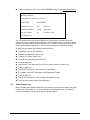
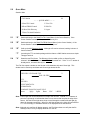
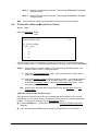
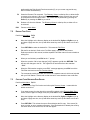
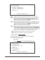
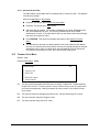
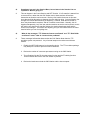
2.4
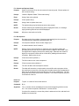
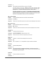
START-UP SCREEN
Session: Main
Path from Main Menu: Ctrl-RET
M
C N C Station
V02.02 press
return
to
start
© 1992-3 Greco Systems
This screen shows the product name, copyright notice, network type, and the version level of the
internal software. The actual version number shown will vary as the firmware is updated.
2.5
Ctrl-C
Brings up the CNC Station H/W Configuration screen.
RETURN
Brings up the Main Menu.
KEYBOARD
Most of the keys on the keyboard are functional. However, the following keys are not
implemented because their functions are not supported by the CNC Station hardware, or because
other keys provide that functionality.
NUM LOCK
SCR LOCK
PRTSC
BREAK/PAUSE
ALT
FN
Some of the other keys only work in certain menus, screens or modes. Typical of these are the
function keys F1 through F10, the arrow keys, PgUp, PgDn, Home and others.
The CAPS LOCK key works, but some editable items force everything to upper case for
compatibility with DOS directories and other system interfaces.
CNC Station ™ User Manual
4
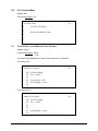
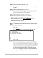
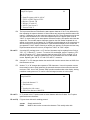
3.0
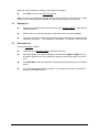
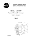
SESSIONS
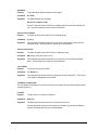
Session Menu
Session: none
Path from anywhere: Ctrl-space
Session Menu
cdimnv
C – MTC Comm V – File Viewer
D – Disk Functions
I – Errors/Messages
M * Main Session
N – NetFile Transfer
The CNC Station has a very useful feature called “sessions”. You can use every function of the
CNC Station without understanding sessions, but you can use only one function at a time.
Understanding sessions allows you to do more than one thing at a time.
The Session List is located on the right end of the top line of the screen. It is always displayed,
no matter what else is going on. The list is composed of one or more letters, in alphabetical
order. Each letter represents one active session. The letter representing the session you are
currently in is UPPER case, all the rest are in lower case.
Mnv
Sample Session List
The CNC Station menu tree is broken up into several sections. Each section is handled by a
different session. Each session can perform a function at the same time as other sessions. The
menu tree is setup such that you can use all of the functions, one at a time, and the sessions are
switched automatically.
If you watch the Session List while you move around the menu tree, you will notice that at certain
points, letters come and go. Each letter represents an active session. Each session is activated
and deactivated as you move in and out of its portion of the menu tree.
While a function is being performed by one session, another session can do something else.
The contents of this menu vary, depending on what sessions are active. This example shows
about the most you will ever see. The Main Session will always be present. Note that all of the
letters in the Session List are lower case. This shows that you are not in any session.
The session with the asterisk “*” between its ID and description is the session that you just left.
Space
RETURN
Switch to the next session in the list (the one after the one with the asterisk).
Returns to whatever session you were in (the one with the asterisk).
CNC Station ™ User Manual
5
ID letter
ESC
Switches directly to the session matching the letter you typed. It must be one of
those shown on the menu, which only includes active sessions.
Switches directly to the Main Session.
Ctrl-T Toggles the Test Session on and off.
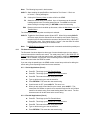
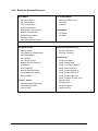
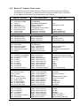
3.1
SESSIONS LIST
“M” Main Menu
“C” Comm Session
“V” File Viewer
“E” File Edit Session
“N” Network File Transfer
“D” Disk Special Functions
“I” Information (special)
“P” Display Comm Output Data (special)
“T” TTY Emulation Session
The Main Menu Session is always active. Many functions are handled by the Main Menu Session
directly. Other sessions are activated automatically as needed to access their respective portions
of the overall menu tree.
The Comm Session (ID letter “C”) controls and monitors file transfers between the CNC Station
and the Machine Tool Control. Both the SEND and READ menus are handled by the Comm
Session, but only one at a time. The activity monitor screens for SEND and READ operations
activate and deactivate automatically for all file transfers, even those that are started remotely.
The Display Comm Output Data (ID letter ”P”) starts automatically when the Comm Session starts
sending data to the machine tool control. It displays data as it is sent to the control. The user
can switch between the Comm Session and Display Data session by using the space key. The
Display Data session will continue until the Comm Session is exited, even after all the data has
been sent to the control.
The View Session (ID letter “V”) runs the read-only file viewer.
The Edit Session (ID letter “E”) runs the text file editor.
Note: You cannot view a file and edit a file at the same time.
The Network file Transfer (NFT; ID letter “N”) session controls and monitors file transfers between
the CNC station and the network file server. The Network File Transfer Menu is handled here.
The activity monitor screens for GET and PUT operations activate and deactivate automatically
for all network file transfers, even those that are started remotely.
The Disk Special Functions (DSF; ID letter “D”) session handles the menu of the same name.
These are disk functions that require some time to complete.
The Information Session (ID letter “I”) is different; it has no menu functions to perform. Its job is
to display certain information and error messages. When one of these messages needs to be
displayed, the Info session will ‘pop-up’ with the message. Once the message is acknowledged
(see the screen for the proper key), the Info session goes away and the screen returns to
whatever was interrupted. Note that processing continues in the interrupted session even while
the message is displayed.
CNC Station ™ User Manual
6
The TTY emulation session transforms the CNC Station into a Teletype (c) terminal. The user
can choose to capture data received by and keyed into the terminal TTY emulation can also send
files.
3.2
SESSION SWITCHING
When performing functions one at a time from the Main Menu tree, you are switched
automatically form one session to another and back. However, it is possible to manually switch
between active sessions. This allows you to start a function in one session, switch back to the
Main Menu Session while that function is still running, and do something else at the same time.
The list of letters in the top right-hand corner of the screen shows the sessions that re active at
that time. The Main Menu Session is always active; the others come and go, as they are needed.
Each session is identified by a single letter, and the list is always in alphabetical order.
You can always tell what session you are in by finding the one letter in upper case (capitals).
There are two ways to manually change sessions.
1.
Press the Shift-space key. This switches to the next session in the Session List. When
it gets to the end, it starts over with the first.
2.
Press the Ctrl-space key. This brings up the Session Menu. This shows the ID letters
and names of all active sessions. The session that you were last in has an asterisk (“*”)
next to it, the others have dashes (“-“).
From the Session Menu the RETURN key returns you to the same session, the space
key switches you to the next session (same as typing shift-space), and typing the letter
of any active session switches you directly to that session (i.e., typing M switches you to
the S Session).
Remember that each session runs independently of the others, so the screen displayed
when you return to a session may not be the same as when you left. This is especially
true for the Comm Session and NFT Session. These sessions have status monitoring
screens that appear automatically whenever a file transfer is in progress.
Note: When you are in the Session Menu, all session ID letters will be lower case. This
is because the Session Menu is not a session, it merely provides a way to switch
between sessions.
CNC Station ™ User Manual
7
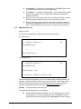
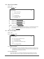
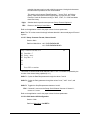
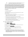
4.0
OVERVIEW OF MENUS
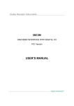
4.1
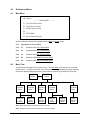
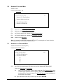
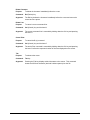
MAIN MENU
CNC Station
⎯ ⎯ MAIN MENU ⎯ ⎯
F1 File TRANSFER Menu
F2 FILE Functions Menu
F3 DISK Functions Menu
F4
F5 NETWORK
F6 Special Functions Menu
All of the following functions are available from the Main and Quick menus.
4.2
4.1.1
Type space for QUICK MENU
4.1.2
F1
Switches to the File Transfer Menu
4.1.3
F2
Switches to the File Functions Menu
4.1.4
F3
Switches to the Disk Functions Menu
4.1.5
F5
Switches to the Network Functions Menu
4.1.6
F6
Switches to the Special Functions Menu
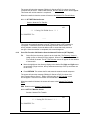
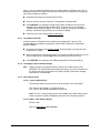
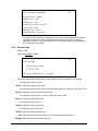
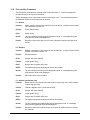
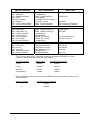
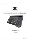
MENU TREE
All functions are selected from on-screen menus. The Main Menu is the top level of a tree with
several levels. To perform a function, move to the proper menu by pressing the proper keys (the
choices are always displayed on-screen), then select the function by pressing its function key.
Sign-on
Screen
Main/Quick
Screen
File
Transfer
Menu
File
Functions
Menu
Disk
Functions
Menu
Network
Functions
Menu
Send File
To
Control
Read File
From
Control
Disk
Special
Functions
Network
File
Transfer
Special
Functions
Menu
Network
Redirect
Menu
Setup
Control
Menu
Note: Single letter paths from Quick Menu are not shown.
Note: Individual function screens are not shown, only main menus.
CNC Station ™ User Manual
8
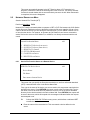
4.3
MOVING AROUND THE MENUS
Each menu has a list of functions than can be selected from that menu. You choose the item by
pressing the key listed to the left of the description.
For example, one of the items on the Main Menu is “F3 DISK Functions Menu,” pressing the F3
key will switch to the Disk Functions Menu.
To move back up the menu tree, press ESC.
Combinations of the keys are used on some menus. They are always shown in the same way, as
follows:
F3
Means to press the F3 key by itself.
SF3
Means to hold down either SHIFT key while pressing the F3 key.
CF3
Means to hold down the CONTROL key while pressing the F3 key.
If the key is followed by a dash “-“ or equals sign “=”, do NOT type the dash or equals sign, just
the function key or letter before it.
D
Means to press the D key
A few screens have the function key choices listed along the bottom line (such as the Directory
Viewer). In some cases a help screen can be called up by pressing the question mark”?” to
explain what each key does (Note: the question mark is a SHIFTED character.)
When you see the word “arrows” on the bottom of the screen, this means that you can use the
arrow keys to move the cursor or highlight around on the screen. The backspace key looks very
similar to the left arrow key, but they are NOT the same.
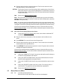
4.4
INPUTTING DATA INTO MENUS
Some menu items allow you to change an operating parameter. These are always displayed with
an equals “=” sign between the item name and the item’s current setting. This says that the item
named to the left of the equals sign is set to the value displayed to the right of the equals sign. It
also means that the function key listed to the left of the whole thing will let you change that value.
For example, one of the lines on the Special Functions Menu is: F6 LCD Adjust = 10. This
means that the current setting of the “LCD Adjust” parameter is 10. It also says that pressing the
F6 key will change it.
Different ways are used to change different kinds of items. Whit some items, pressing the
function key will cycle it to the next one of a fixed sequence of valid values (such as in our
example.) When it gets to the last value, it starts over at the beginning of the list. In other cases,
you edit the item directly on-screen (such as the Switch Reg on the Setup: Parallel Channel (2)
screen). And when the item is a filename (such as the “File” item on the Send File TO Control
menu), it will call up the Directory Viewer, which lets you select one of the files on a diskette, or
type in the name of a new file.
Refer to Section 11.0, “Menus and Screens References,” for details on what values can be
assigned to each parameter, and how each one can be changed.
4.4.1
Editing Values On-Screen
Whenever you need to edit a value on-screen, the same editing keys are available.
When editing, the cursor will appear on the first (left-most) character of the value. You
can move the cursor left and right, type letters or numbers, and a few other things. When
you are done, press the RETURN key to save the new value. If you make a mistake or
change your mind press the ESC key to cancel the changes.
CNC Station ™ User Manual
9
While editing a value, that value occupies a fixed amount of space on the screen. You
can move the cursor within that area, but cannot move it elsewhere on the screen. This
area is called the ‘field’. A field is always limited to one or more characters on a single
line.
The following keys can be used while editing a parameter on-screen:
The left arrow key moves the cursor one character to the left, without changing
anything.
The right arrow key moves the cursor one character to the right, without changing
anything.
Home Moves the cursor to the left end of the field.
End Moves the cursor to the first blank after the character in the field. If the last
character is at the right-most edge of the field, the cursor will be on that
character.
ESC
RETURN
Ends the edit, cancels any changes made and returns the item to its original
value.
Ends the edit and saves the new value of the item (Note: this does NOT change
the value saved in the EEROM).
Ctrl-J
Moves the cursor one character to the left, without changing anything
Ctrl-K
Moves the cursor one character to the right, without changing anything
Ctrl-H
Moves the cursor to the left end of the field
Ctrl-L
Moves the cursor to the first blank after the last character in the field. If
the last character is at the right-most end of the filed, the cursor will be on
Depending on what is being edited, different sets of keys can be typed in the field.
Filenames and other text fields:
Type any letter, digit, or punctuation
For numeric fields:
(such as Reader Speed)
Only type digits 0 through 9
For binary fields”
(such as the Config. Reg.)
Type only the digits 0 and 1
CNC Station ™ User Manual
10
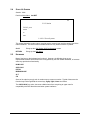
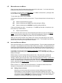
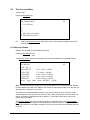
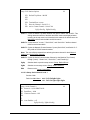
5.0
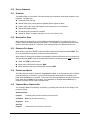
QUICK MENU
Session: Main
CNC Station
M
⎯ ⎯ QUICK MENU ⎯ ⎯
S-Send TO Control
V-View File
R-Read FROM Control
E-Edit File
D-Show Disk Directory
L-Logon
T-Enter Terminal Emulation
5.1
“S”
Switches directly to the Send File TO Control Menu (in the Comm Session). If the
Comm. Session is already active, we switch directly to it.
5.2
“R”
Switches directly to the Read File FROM Control Menu (in the Comm Session). If the
Comm Session is already active, we switch directly to it.
5.3
“D”
Calls up the disk Directory Viewer. Although a file can be selected, nothing is done to it
from this function.
“T”
Launches the TTY emulation package with the feature a CNC Station serves as a simple
Teletype Terminal.
“V”
Starts the text File Viewer. The Directory View is called up first, to allow a file to be
selected. When a file is selected, the File View is started on it. If the ”V” or “E” session is
already active, we switch directly to it.
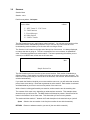
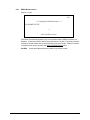
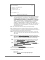
5.4
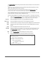
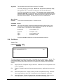
The File View opens a window on the file that is 38 characters wide and 6 lines high. This
window can be moved up and down and left and right across the file.
VIEW FILE: FILENAME.TEX
V
TOP= OF=FILE
: G71
: N1G9Z 0.
: N2G17M99T10Z 0.
: N3M06T00Z 0.
: N44G00X 524.894Y-434.443Z 250.Z
arrows
PgUp
PgDn
Home
ESC
?=HELP
Note: Lines longer than 38 characters do not wrap to the next line. Instead, a “>” character is
put in the right margin to indicate that there is more text on that line past the edge of the
screen. Use the left and right arrow keys to scroll through the window left and right (by
about 20 characters each time). When you shift the window to the right, all lines will have
a “<” in the left edge, to indicate that there is un-displayed text in that direction.
Note: Although only text files will display properly, the File Viewer does not verify that the file
actually is text; it will try to display whatever is in the file.
CNC Station ™ User Manual
11
5.5
“E”
“L”
Starts the File Editor. The Directory Viewer is called up first, to allow a file to be selected.
When a file is selected, the File Editor is started on it. If the “V” or “E” session is already
active, we switch directly to it.
Logon enters the security menu screen.
Ctrl-RET Returns to the Start-up Screen.
CNC Station ™ User Manual
12
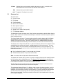
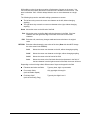
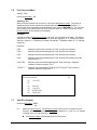
6.0
FILE TRANSFER MENU
Session: Main
Path from Main Menu: F1
File Transfer Menu
F1
F2
F3
F4
F5
F6
6.1
M
Send File TO Control
Read to File FROM Control
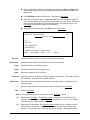
TO SEND A FILE TO THE MACHINE TOOL CONTROL
Session: Comm
Path from Main Menu: F1 F1
or S
This screen varies depending on which communications port is selected.
For serial (port 0):
Send File TO Control
SF1
F2
F3
F4
F5
F6
Cm
START Sending
File = <none>
Serial Search = OFF
Search String = <none>
For parallel (port 2):
Send File TO Control
Cm
SF1 START Sending
F2 File = <none>
F3
F4
F5 Search String = <none>
F6
CNC Station ™ User Manual
13
Note:
The following keys work in both screens:
Shift-F1 Starts sending the specified file to the Machine Tool Control. If file is set
to”<none>”, nothing will happen.
F2
Calls up the Directory Viewer to select a file for the SEND.
F5
Allows the Search String to be edited. Up to 16 characters can be entered.
Leading spaces count, but trailing spaces do not. Press ESC to exit mode
without saving the changed string, or RETURN to save the new string.
Returns to the menu that called up this screen, either the Main Menu or the File
Transfer Menu.
ESC
The following key works only when a serial port is selected:
Shift-F4 Toggles the Serial Search option ON and OFF. When ON, pressing Shift-F1
will cause output from the selected file to the machine tool control to begin at
the point in the file that matches the contents of the Search String. When OFF,
the entire file is sent. If the search string is “<none>”, then the entire file will be
sent regardless of the setting of the search mode.
Note:
6.1.1
The SEND Monitor Screen provides search commands used with the parallel port.
File Search Functions
The file search functions depend on what type of communications port you are using to
communicate with the machine tool control. For serial ports (0 and 1), the SEND File TO
Control menu allows you to edit the search string, and enable or disable the search
function. When enabled, only that part of the file starting with the matched string will be
sent to the control when the SEND is started.
If you are using the parallel port, the SEND monitor screen has provisions for editing the
search string, and requesting forward and reverse searches.
6.1.1.1 Serial Applications (Port 0)
Press F1. This brings up the File Transfer Menu.
Press F1. This brings up the SEND File TO Control menu.
Press F5. This enters the search string edit mode.
Type or edit the string you want to search for.
Press RETURN. This saves the new search string.
If serial search is OFF, press shift-F4. This turns it on.
When you are ready to send the file to the control, press shift-F1. This
causes the CNC Station to open the file, search through the file until it finds a
match for the search string, then starts sending data to the control. The first
characters sent will be the same as the search string.
6.1.1.2 Parallel Applications (Port 2)
Press F1. This brings up the File Transfer Menu.
Press F1. This brings up the SEND File TO Control menu.
Press F5. This enters the search string edit mode.
Type or edit the string you want to search for.
Press RETURN. This saves the new search string.
CNC Station ™ User Manual
14
Press Shift-F1. This opens the file and brings up the SEND Monitor screen
(we expect that the control is not accepting data yet).
Press Shift-“>”. This starts a forward search. The file pointer will be moved
forward until a match is found. Progress and completion messages will
appear as warranted.
At this point, you can search for the next occurrence of the string, or edit the
string and search for something else, or you can search in reverse.
When you are at the proper point in the file, tell the machine tool control to
start accepting data (push a button on the control, or whatever makes it do
that). The first thing sent will be the same as the last search string found.
6.1.2
SEND Monitor Screen
Session: Comm
This screen varies depending n which communications port is active.
For serial (port 0):
* * * Send File TO Control * * *
Cm
File SOMEFILE.TEX
-->Press Ctrl-ESC to close
For parallel (port 2):
* * * Send File TO Control * * *
Cm
File SOMEFILE.TEX
F5 Search String = <none>
“<”=REVsrch “>”=FWDsrch Ctrl-ESC=CLOSE
This screen automatically appears in the Comm Session when a SEND operation is in
progress. It shows the name of the file being sent to the control. The activity indicator
consists of several dashes with an arrow that slowly moves to the right. When the
transfer is completed, the screen returns to the Send File TO Control menu.
Ctrl-ESC
Closes (aborts) the send operation.
For parallel, the following keys are also available:
F5
CNC Station ™ User Manual
Allows the Search String to be edited. Up to 16 characters can be entered.
Leading spaces count, but trailing spaces to not. Press ESC to exit edit
mode without saving the changed string, or RETURN to save the new string
15
Shift-“>” Issues a Forward Search command. The message “SEARCHING” will appear
during the search.
Shift-“<” Issues a Reverse Search command. The message “SEARCHING” will appear
during the search.
Note:
6.2
Once a search is started, you cannot abort it or close the file until it is finished.
TO READ A FILE FROM THE MACHINE TOOL CONTROL
Session: Comm
Path from Main Menu: F1 F3
or R
Read File FROM Control
Cm
SF1 START Reading
F2 File = <none>
F3
F4
F5
F6
One of the items on this menu shows the name of the file to be read. If no filename has been
entered, it shows <none>”. If it already shows the name of the file you want to read, press Shift-F1.
Shift-F1
Starts reading a file from the Machine Tool Control using specified filename. If the
filename is set to”<none>”, nothing will happen.
F1
Calls up the Filename/Mask Entry screen. Type in the name of the file you want to
create, then press Shift-F1.
F2
Calls up the Directory Viewer to select a filename to read to. If an existing filename is
selected, it will be overwritten when the read is started. To enter a new filename,
press F1 at the Directory Viewer to enter the Filename/Mask Entry screen. Press
return when completed.
ESC
Returns to the menu that called up this screen, either the Main Menu or the File
Transfer Menu.
Initiate file output from the machine control.
Some protocols close the file at the end of a read automatically, but others do not. It is also
possible that you may want to close the file before it finishes as a result of errors or some other
problem. To close the file manually from the Read Monitor screen:
Press the Ctrl-ESC key. The file will be closed and the READ File FROM Control menu
reappears.
If you were canceling the READ and do not want to keep the file, be sure to delete it.
CNC Station ™ User Manual
16
6.2.1
READ Monitor Screen
Session: Comm
Cm
* * * Reading File FROM Control * * *
File SOMEFILE.TEX
-->Press Ctrl-ESC to close
This screen automatically appears in the Comm Session when a READ operation is in
progress. It shows the name of the file being read from the control. The activity indicator
consists of several dashes with an arrow that slowly moves to the left. When the transfer
is completed, the screen returns to the Read File FROM Control menu.
Ctrl-ESC
CNC Station ™ User Manual
Closes the Read and saves any data not yet written to disk.
17
7.0
FILE FUNCTIONS MENU
Session: Main
Path from Main Menu: F2
Selecting a File
When a function requires a file to work on, it will call up the Directory Viewer. This show an
alphabetical list of all files stored on the selected disk drive. The top file is highlighted. To
choose a file, move the highlight to the desired file, then press the RETURN key. You can also
use a function key to allow you to type in the full name of the file. Refer to the section on the
Directory Viewer in this manual for more details.
File Masks
If the listing of files in the Directory Viewer is too long, you can specify a file mask. The special
characters “?” and “*” can be used to limit the list of files displayed. A ”?” matches any single
character, while the “*” matches any number of characters. The default masks of “*.*” matches
everything.
Examples:
FOO.*
Matches only files with a filename of “FOO”, but with any extension.
FOO*.*
Matches only filenames starting with “FOO” and with any extension.
FOO*
Matches only filenames starting with “FOO” and with any extension.
FOO*.
Matches only filenames starting with “FOO” and with NO extension (note the
period after the “*”).
FOO?.TEX
Matches only those filenames starting with “FOO”, with only 1 additional
character, and the extension “TEX”.
??FOO*.T?
Matches only filenames with “FOO” as the 3rd through 5th letters, and a 2character extension starting with “T”.
File Functions Menu
F1
F2
F3
F4
F5
F6
7.1
M
View File
Edit File
Copy File
Rename File
Delete File
VIEW (FILE VIEWER)
Path from Main Menu: F2 F1
or V
F1
Starts the text File Viewer. The Directory Viewer is called up first, to allow a file to be
selected. When a file is selected, the File Viewer is started on it. If the “V” or “E” session
is already active, we switch directly to it.
The Directory Viewer will be displayed in File View mode.
CNC Station ™ User Manual
18
Move the highlight on the directory display to the desired file (PgUp and PgDn move
up and down a page at a time, the up and down arrow keys move up and down one
file at a time).
Press RETURN to select the desired file. This starts the File Viewer.
Move around the file as desired. PgUp and PgDn moves up and down a page at a
time. The up and down arrow keys scrolls up and down one line at a time, and the left
and right arrow keys shifts the file left and right by about 20 characters each. See
File Viewer in the reference section for more options.
When you have seen enough, press ESC to exit the File Viewer.
VIEW FILE: FILENAME.TEX
mV
TOP= OF=FILE
: G71
: N1G9Z 0.
: N2G17M99T10Z 0.
: N3M06T00Z 0.
: N44G00X 524.894Y-434.443Z 250.ZZ
arrows
PgUp/PgDn
Home
ESC
?=HELP
Up arrow
Scrolls the window up one line (the file moves down in the screen)
Down arrow
Scrolls the window down one line (the file moves up in the screen)
PgUp
Scrolls the window up one page (6 lines)
PgDn
Scrolls the window down one page (6 lines)
Home
Moves the window to the top of the file
Left arrow
Right arrow
“?”
ESC
Shifts the window to the left by 20 columns (another 20 each time). The maximum shift is
100 characters. Note that this is a shifted character.
Shifts the window to the right by 20 columns, but not past column 0. Note that this is a
shifted character.
Brings up a help screen, which shows the functions available in the File Viewer.
Exits the File Viewer.
Note: It is not possible to view a file at the same time the File Editor is active.
F3
Starts the text File Editor. The Directory Viewer is called up first, to allow a file to be
selected. When a file is selected, the File Editor is started on it. If the “V” or “E” session
is already active, we switch directly to it.
F4
Starts Copy File Command. The Directory Viewer is called up first, to allow the source
file and drive to be selected. Then the file is copied to the other drive using the same
filename. This command only copies from one drive to the other. Note that the copy is
CNC Station ™ User Manual
19
performed by the Disk Special Functions session (D), so you cannot copy and do any
DSF functions simultaneously.
F5
Starts the Rename File command. The Directory Viewer is called up first, to allow the file
to rename to be selected. When the file to be renamed has been selected, the user will
be prompted to enter a new file name. The rename will be performed by pressing the
Enter key or pressing the ESC key to cancel.
F6
Deletes a file from the diskette. The Directory Viewer is called up first, to allow a file to
be selected.
ESC
7.2
Returns to Main Menu.
EDITING TEXT FILES
Path from Main Menu: F2 F3
or E
Move the highlight on the directory display to the desired file (PgUp and PgDn move up
and down a page at a time, the up and down arrow keys move up and down one file at a
time).
Press RETURN to select the desired file. This starts the File Editor.
Edit the file as desired. Refer to the File Editor page in the Menus and Screens
Reference section of this manual, and the separate File Editor manual for more details on
editing files.
When you are finished, press ESC at the “*” prompt.
When the question “OK to lose changes [Y/N]?” appears, type N, then RETURN. This
will save the changes to the file. The original file is renamed to have the extension
“.BAK”.
When the “Edit session complete, enter ESC” message appears, press ESC to exit the
File Editor and return to the File Functions Menu.
The commands used by the editor are covered in a separate manual, which was included
with your CNC Station. Please refer to that manual for more details on how to edit files.
7.3
COPYING FILES BETWEEN DISK DRIVES
Path from Main Menu: F2, F4
This selects the Copy File function and calls up the Directory Viewer. It starts with the
default comm drive.
If you want to copy from the other drive, press F1 to switch to the Filename/Mask Entry
screen, then F1 again to change drives, the press ESC to return to Directory Viewer.
Move the highlight on the directory display to the desired file (PgUp and PgDn move up
and down a page at a time, the up and down arrow keys move up and down one file at a
time).
Press RETURN. This selects the source file and begins the file copy. If the source file
does not exist, an error message will appear. If the destination drive already has a file by
the same name as the source file, an error will appear.
CNC Station ™ User Manual
20
When the copy is finished, the message “Copy finished” will appear.
Press ESC to return to the File Functions Men.
Note: The Copy File command only copies from one drive to the other, or the other way. It does
not allow you to change the name of the file, or copy to another name on the same disk.
7.4
RENAME FILE
This selects the Rename File function and calls up the Directory Viewer. It starts with the
default comm drive.
Select the file to be renamed using the up and down arrow keys and press Enter.
Type in the new name for the file using the DOS naming convention which has a limit of 8
characters, followed by “.” Then followed by 3 characters. For example: XXXXXXX.XXX
7.5
DELETING FILES
Path from Main Menu: F2, F6
This brings up the Directory Viewer in the Delete File mode.
Move the highlight on the directory display to the desired file (PgUp and PgDn move up
and down a page at a time, the up and down arrow keys move up and down one file at a
time.).
Press RETURN to select the desired file. This selects the file and brings up a verification
screen
If you really want to delete the file, press F1. If you changed your mind, or selected the
wrong file, press ESC to cancel.
CNC Station ™ User Manual
21
8.0
DISK FUNCTIONS MENU
Session: Main
Path from Main Menu: F3
Disk Functions Menu
M
F1 View Directory
F2
F3
F4
F5 Show Space On Diskette
F6 Disk Special Functions
F1
Calls up the Directory Viewer. Although76 a file can be selected, nothing is done with it
from this function.
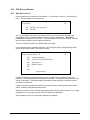
8.1 DIRECTORY VIEWER
Session: Can be used by several different sessions
Path from Main Menu: F3 F1
or D
The Directory Viewer provides a full-screen view of the list of filenames in a diskette directory.
Disk Directory
M
F1Dir – D0:*.*
ANOTHER FIL
1,565 2/03/92 3:00PM
FILE01.TEX
375 12/04/91 8:40AM
FILE02.BIN*
5,606 1/01/01 12:00AM
FILE02.TEX
8,430 12/04/91 9:58PM
MOREFILE
89,086 4/19/89 1:00AM
arrows PgUp PgDn Home RETRUN ?=HELP
Note: The date and time will usually be correct for files written on a PC and newer CNC Stations,
but since Minifiles and older CNC Stations do not have an internal time-of-day clock, the time and
date may not be accurate for some files.
The names are sorted alphabetically, and you can see five names at a time. Each line on the
screen shows the name of the file, the size of the file in bytes, and the date and time the file was
written. One name is highlighted (it has an asterisk "*" to the right of the name), and you can
change which one that is.
The Directory Viewer also has a filemask parameter. Pressing F1 calls up the Filename/Mask
Entry screen. This screen allows you to change drives, enter a filemask, or enter the full filename.
Enter a full filename is useful when creating a new file, since you can't select something that isn't
there yet
CNC Station ™ User Manual
22
The Directory Viewer is also used by numerous other functions to allow the user to select a file to
process.
The title on the top line will show the name of the function that called up the directory, such as
SEND. When called by itself, the title is as shown.
The last line shows some of the keys which perform functions in the Directory Viewer. This
screen also has a HELP screen which provides longer explanations of those keys.
The five middle lines show up to five file entries from the disk directory .The filename, size, date,
and time are shown. The files are shown in alphabetical order.
One file is always highlighted. The highlight consists of an asterisk "*" to the right of the filename.
F1
Up arrow
Down arrow
Calls up the Filename/Mask Entry screen. This allows you to change the file mask, or just
type in the full filename. It also allows you to change which drive you are looking at.
Moves the highlight to the next file. The list is paged down as needed.
Moves the highlight to the previous file. The list is paged up as needed.
PgUp
Scrolls the window up one page (5 lines) and moves the highlight up by the same amount
PgDn
Scrolls the window down one page (5 lines) and moves the highlight down by the same
amount
Home
Moves the highlight and the window to the first file in the list
RETURN
ESC
"?"
Performs a function on the selected file. The function that is performed depends on how
the Directory Viewer was started. For example, if started from the "Delete File" menu
pick, the file would be deleted.
Exits the Directory Viewer without selecting a file or doing a function.
Brings up a help screen. This screen shows what the function keys do.
HELP: Directory Viewer
M
arrows = move to prev/next file
PgUp/PgDn = show previous/next page
Home = move to first file
F = type name or change mask
ESC = cancel
RETURN = select marked file
CNC Station ™ User Manual
23
8.1.1
Filename/Mask Entry Screen
Path from Directory Viewer: F1
SPECIFY FILE/MASK:
M
F1 Drive = D0:
Enter file name or file mask
**
RETURN=Select
F1
ESC
RETURN
ESC = Show Dir
Cycles the disk drive parameter through the values "D0:" and "D2:".
Returns to the Directory Viewer with no changes to the filemask. It does allow
changes to the drive selection.
If a filemask was entered, returns to the Directory Viewer. which re-reads the
directory with the new filemask and/or drive selection. If a complete filename was
entered, the function is performed on the file (same as pressing RETURN from
the Directory Viewer screen when the filename already exists). If left blank, the
default mask of "*.*" is used.
Field Editing keys are active.
Other keys are entered into the field at the cursor position. If the result contains one or
more question marks "?" or asterisks "*", it is a filemask, otherwise it is a complete
filename.
8.2
SHOW SPACE DISK
Session: Main
Path from Main Menu: F3 F5
DISK SPACE
M
F1 Drive = D0:
bytes
F1
ESC
Note:
blocks
used
126,976
248
free
1,330,688
2599
total
1,4f57,664,
2847
Cycles the Drive selection through the values "D0:" (floppy disk) and "D2:" (RAM disk).
Returns to the Main Menu.
There may be a delay of 2 or 3 seconds before the results appear. This occurs while the
disk is being read, and will happen when first called up, and each time the F1 key is
pressed to change drives.
CNC Station ™ User Manual
24
If you change diskettes, you must exit this screen, and re-enter it to read the new diskette.
F5
ESC
8.3
Calls up the Disk Space screen. It shows the total storage space on the disk, the amount
of space used, and amount of space available. Both the number of blocks (512 bytes
each), and number of bytes are reported (do not add them together, they are different
ways of measuring the same thing).
Returns to the Main Menu.
DISK SPECIAL FUNCTIONS
Session: Disk Special Functions
Path from Main Menu: F3 F6
Disk Special Functions
Dm
F1 Verify Diskette (read only)
F2
F3
SF4 INIT Diskette (erase dir)
SF5 FORMAT Diskette (erase everything)
SF6 Test Diskette (erases everything)
These functions operate on the default comm drive only.
8.3.1
Verify Disk
Session: Disk Special Functions (DSF)
Path from Main Menu: F3 F6 F1 RETURN
Verifying Disk
Current Block Number:
Dm
104
Read Errors: 0
Seek Errors: 0
ESC=STOP
This test performs a non-destructive test on a diskette (the contents of the disk are NOT
damaged). It reads each block on the diskette to verify that there are no errors. All read and seek
errors are counted. When it gets done, it stops.
ESC
Stops the verify (if not already done). When the message "Verify complete, press ESC"
appears, press ESC again to return to the Disk Special Functions menu.
The Current Block Number counts from zero to the maximum block number of the disk. The error
counters start at zero, and show all errors that occurred since the verify was started.
8.3.2
Initialize Diskette
Session: Disk Special Functions (DSF)
CNC Station ™ User Manual
25
Path from Main Menu: F3, F6, SF4
SF4 Initializes a diskette by erasing the directory. The diskette must already be
formatted.
The screen prompts for volume name. You can also use F1 to change drives. Enter the
volume name and press RETURN. Then the screen shows the message "Initializing Disk
..." while the format is performed. When finished, it returns to the Disk Special Functions
Menu.
8.3.3
Format a New Diskette
Session: Disk Special Functions (DSF)
Path from Main Menu: F3, F6, SF5
SF5 Formats a diskette. This erases ALL data from the diskette. Most new diskettes
must be formatted before they can be used. When finished, the disk has no files on
it, and all space is free.
WARNING: This will permanently erase ALL data from the diskette.
If the wrong drive is displayed, press F1 repeatedly until the desired drive is
shown.
If desired, type in the volume name. It can be from 1 to 11 letters or digits, no
spaces. If you omit it, the default volume name of "CNC-STATION" is used.
Put a diskette in the drive. (This does not apply to RAM disks.)
Press RETURN. This starts the format operation. The format may require a
minute or two to complete.
When the format is completed, the Disk Special Functions Menu returns.
The screen prompts for new volume name. You can also use F1 to change drives. Enter
the volume name and press RETURN. Then the screen shows the message "Initializing
Disk ..." while the format is performed. When finished, it returns to the Disk Special
Functions Menu.
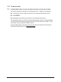
8.3.4
Test Disk
Session: Disk Special Functions (DSF)
Path from Main Menu: F3, F6, SF6
Note: This menu cannot be accessed while a Copy File command is running.
Testing Disk
Dm
Current Block Number: 1532
Read Errors: 0
Seek Errors: 0
Writing disk,
CNC Station ™ User Manual
test value = 04
ESC=STOP
26
WARNING: This will permanently erase ALL data from the diskette.
TEST performs a destructive test on a diskette. It writes a test value to every byte of
every block on the disk, then reads each block to verify that they contain the proper data.
All read and seek errors are counted. When it gets done, it starts over with a different test
value. This test runs indefinitely until stopped.
ESC Stops the test. When the message “Disk Test complete, Press ESC” appears,
press ESC again to return to the Disk Special Functions menu. The disk must be
reformatted before it can be used for data storage again.
The last line shows when the test is “Writing” or “Reading” the disk. The current test
value is also shown. The Current Block Number counts from zero to the maximum block
number of the disk, and starts over when switching between reading writing phases. The
error counters start at zero, and show all errors that occurred since the test was started.
The test value will vary.
Note: The diskette must be formatted BEFORE running this test. If already formatted,
ALL data on the disk will be erased. .
Note: The disk must be formatted after running this test before it can be used for data
storage again.
CNC Station ™ User Manual
27
9.0
NETWORK FUNCTIONS MENU
Session: Main
Path from Main Menu: F5
Network Functions Menu
F1
F2
F3
F4
F5
F6
M
Network File Transfer Menu
Network Redirection Menu
Server Directory Menu
Print Server File Menu
F1
Switches to the Network File Transfer Menu.
F2
Switches to the Network Redirection Menu.
F4
On RS-232 network only, switches to Server Directory Menu.
F5
On RS-232 network only, switches to Print Server File Menu.
ESC
Returns to the Main Menu
Note: If a network file transfer is in progress (GET or PUT), selecting either of these functions
will simply switch you to the Network Monitor screen.
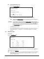
9.1
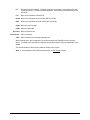
NETWORK FILE TRANSFER MENU
Session: Network File Transfer (NFT')
Path from Main Menu: F5 F1
Network Transfer Menu
mN
F1 GET File FROM Server
F2 PUT File TO Server
F3
F4
F5
F6
9.1.1
Get a File From the Network File Server to the CNC Station (NFT Download)
Start at the Main Menu or Quick Menu.
F1
Gets a file from the server (copies it to the local disk). The Filename Entry screen
is called up first to allow a file to be entered. When a filename has been entered,
the Network File Transfer is started. The NFT GET Monitor screen will appear for
the duration of the transfer.
Type in the name of the file you want to get, then press RETURN.
CNC Station ™ User Manual
28
The screen will show the message "Waiting for Server to Poll" for a short time, then
"Request Sent to Server”. Within a few seconds, the GET Monitor screen should appear.
This screen will until the transfer is completed.
When the transfer is done the screen will return to the Network File Transfer Menu.
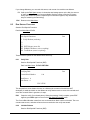
9.1.1.1. NFT GET Monitor Screen
Session: Network File Transfer
mN
* * * Getting File FROM Server * * *
File SOMEFILE.Tex
- > -This screen automatically appears in the NFT Session when a GET operation is
in progress. It shows the name of the file being read from the file server. The
activity indicator consists of several dashes with an arrow that slowly moves to
the right. When the transfer is completed, this screen disappears.
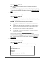
9.1.2
Put a File From the CNC Station Onto the Network File Server (NFT Upload)
F2
Gets a file from the server (copies it to the local disk). The Directory Viewer is
called up first, to allow a file to be selected. When a file is selected, the Network
File Transfer is started. The NFT PUT Monitor screen will appear for the duration
of the transfer.
Move the highlight on the directory display to the desired file (PgUp and PgDn move
up and down a page at a time, the up and down arrow keys move up and down one
file at a time).
Press RETURN. This selects the file and starts the network transfer sequence.
The screen will show the message "Waiting for Server to Poll" for a short time,
then "Request Sent to Server". Within a few seconds, the PUT Monitor screen
should appear. This screen will remain until the transfer is completed.
When the transfer is finished, the screen will return to the Network File Transfer
Menu.
ESC Returns to the Network Functions Menu.
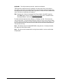
9.1.2.1 NFT PUT Monitor Screen
Session: Network File Transfer
mN
* * * Putting File TO Server * * *
File SOMEFILE.Tex
- > -CNC Station ™ User Manual
29
This screen automatically appears in the NFT Session when a PUT operation is in
progress. It shows the name of the file being sent to the file server. The activity indicator
consists of several dashes with an arrow that slowly moves to the left. When the transfer
is completed, this screen disappears.
9.2
NETWORK REDIRECTION MENU
Session: Network File Transfer (NFT)
Path from Main Menu: F5 F2
Network File Transfer commands allow an operator to GET or PUT files between the CNC Station
and the file server. Redirection refers to the ability to have the file server transfer a file to or from
a device other than the one you are issuing the command from: you can SEND or SAVE a file to
or from the other device. For instance, an operator at CNC Station A can issue a command to
send a file from the server to CNC Station B, or a Minifile, or a directly connected machine tool
control.
Network Redirection Menu
F1
F2
F3
F4
F5
F6
9.2.1
mN
SEND File TO Device (from server)
SAVE File TO Server (form device)
SEND Tile TO Control
GET File FROM control
CLOSE File on Device
DELETE File on Device
Send a File From the Server to a Remote Device
SEND File TO Device/Server
mN
Device Name:
File Name:
Enter name of remote Device
This screen lets you specify the file and remote device to use for a redirected download
(GET). It starts with the cursor in the Device Name field.
First, type in the name of the device you want to send to; this name must match a device
defined on the server. Press RETURN; the cursor moves to the File Name field. Type inthe name of the file to send; this must match the name of a file in the server download
directory for the device named in the Device Name field. Press RETURN; the request will
be sent to the server, which will respond with a message to indicate whether the request
was accepted or not
F1
Calls up the SEND File TO Device entry screen, which allows a redirected GET
command to be issued.
Enter the name of the remote device. This must match a device defined on the
server.
CNC Station ™ User Manual
30
Enter the name of the file to send to that device. This file must exist in the server
download directory of the selected device.
RETURN
ESC
The first time (cursor is in the Device Name field): completes entry of the Device
Name and moves the cursor to the File Name field. The second time (cursor is in
the File Name field): completes entry of the File Name and issues the redirection
request to the server.
Returns to the Network Redirection Menu.
Note: The Device Name and File Name are remembered (as long as the CNC Station
remains turned on) so if the device and/or file name you want is already there, just press
RETURN to accept that entry.
Note: You can have several redirected file transfers running at the same time (as many
as one for each remote device), but you cannot use this command while a GET or PUT is
in progress on this device (including redirected transfers requested from another device).
As soon as the request has been accepted by the server, the screen will return to the
Network Redirection Menu. You can issue another redirected request to another device
immediately, if desired.
9.2.2
Save a File From a Remote Device to the Server
F2
Calls up the SAVE File TO Server entry screen, which allows a redirected PUT
command to be issued.
Enter the name of the remote device. This must match a device defined on the
server. .
Press RETURN. The cursor will move to the filename field.
Enter the name of the file to get from the device. This file must exist on the default
network diskette of the specified device.
Press RETURN. This will send the request to the server. Progress, status, and error
messages will appear as warranted.
As soon as the request has been accepted by the server, the screen will return to the
Network Redirection Menu. You can issue another redirected request to another device
immediately, if desired.
9.3
F3
Calls up the "SEND File TO Control" entry screen which will send a file directly to
a machine control attached to the network.
F4
Calls up the "GET File FROM Control" entry screen which alerts the file server
that a file will be uploaded from a machine control.
F5
Calls up the "CLOSE File ON Control" entry screen which tells a control to close
a file.
F6
Calls up the "DELETE File ON Control" entry screen. The user may name a
control and file. The specified control then deletes the requested file.
ESC
Returns to the Network Functions Menu.
SERVER DIRECTORY MENU
9.3.1
F1
View Device Download Directory
Enter the Device name and the mask for the files to be displayed.
CNC Station ™ User Manual
31
9.3.2
9.4
F2
View Device Upload Directory
Enter the Device name and the mask for the files to be displayed.
PRINT SERVER FILE MENU
9.4.1
F1
Print from Download Directory
Enter the Device name and the File name to be printed.
9.4.2
F2
Print from Upload Directory
Enter the Device name and the File name to be printed.
CNC Station ™ User Manual
32
10.0
SPECIAL FUNCTIONS MENU
Session: Main
Path from Main Menu: F6
Special Functions
F1
F2
F3
F4
SF4
F6
10.1
Setup Control Menu
Set Date and Time
Terminal Setup
Terminal Emulation
LCD Adjust = 10
F1
Switches to the Setup Control Menu.
F2
Switches to the Set Date and Time screen.
F4
Switches to the Set Date and Time screen.
Shift-F4
M
Switches into Terminal Emulation.
F6
Cycles the LCD Adjust setting through the values 0 to 15. Note that the screen may
be unreadable for some settings (so press if repeatedly until you can read it).
ESC
Returns to the Main Menu.
SETUP CONTROL MENU
Session: Main
Path from Main Menu: F6 F1
Setup Control Menu
SF1
F2
F3
SF4
SF5
F6
M
Save setup to permanent storage
Save setup to disk
Load setup from disk
Load setup from permanent storage
View/Change SETUP
10.1.1 Setup Control Menu
SF1 Stores the current system configuration settings in the internal on-volatile memory
chip (EEROM). This allows the settings to be remembered when the power is off,
and restored automatically when turned on.
10.1.2 Save Setup to Disk
This function allows you to create files containing the setup parameters of the CNC
Station. These files can then be loaded on other CNC Stations that require the same
CNC Station ™ User Manual
33
setup, or you can create several files for a single CNC Station for different uses. This is
especially useful when a single CNC Station is connected to a switch box or is frequently
moved from machine to machine.
Press F2. This brings up a Filename Entry screen.
Enter the name to save the setup with. The extension is always “MFP".
Press RETURN. The message "Saving setup to disk" will appear for a short time,
followed by the message "Setup saved to disk". If an error occurs, the message
"Unable to save setup" will appear. This can be caused by running out of space on
the disk, if the disk is write protected, or if no disk is installed.
Press any key to return to the Setup Control Menu.
10.1.3 Load Setup From Disk
Loads the system configuration from a disk file (as created with F2, above). This
overwrites the current system configuration, but does NOT change the configuration
stored in EEROM
Press F3. This brings up the Directory Viewer, which will show only those files with
the extension of "MFP".
Move the highlight on the directory display to the desired file (F5 and F6 move up and
down a page at a time, LF and space move up and down one file at a time).
Press RETURN. This loads the CNC Station parameters from the selected file.
10.1.4 Load Setup From Permanent Storage
SF4
Loads the system configuration from the internal non-volatile memory chip
(EEROM). This is performed automatically upon power up, but this command can
be used to return the configuration to its power-up state if it has been changed
temporarily or unintentionally.
10.1.5 View Change Setup
10.1.5.1 Setup: Default Drives
The following codes are used to refer to the disk drives in the CNC Station:
"D0:" refers to the internal 3 ½" floppy disk drive
"D2:" refers to the internal RAM disk drive (optional)
Note: The "D1:" (second floppy) drive is not available on the CNC Station; these
codes are used to maintain compatibility with other Greco Systems products.
10.1.5.2 Setup: CNC Station Options
Session: Main
Path from Main Menu: F6 F1 F6 PgDn
CNC Station ™ User Manual
34
Setup: CNC Station Options
SF1
SF2
SF3
SF4
F5
SF6
M
Default Top Menu = MAIN
Terminal Port=<none>
Network Channel = Serial Ch 1
Active Comm Channel = Serial Ch 0
PgUp=PrevPg PgDn=NextPg
Shift-F1 Cycles the Default Top Menu between the options "MAIN" and "QUICK". This
setting determines which of the Main and Quick menus are displayed when
returning to the top menu level. Note that in this manual, all references to the
Main Menu refer to both the Main and Quick menus.
Shift-F4 Cycles between "<none>", "Serial Ch 0", and “Serial Ch 1" defines channel
used for terminal emulation.
Shift-F5 Cycles the Network Channel between "(none) Serial Ch 0", and Serial Ch 1".
Only valid on RS-232 network stations.
Note: The user will be prevented from selecting the same channel for both Network
Channel and Active Comm Channel.
Shift-F6 Cycles the Active Communication Channel (to the Machine Tool Control)
through "(none)". "Serial Ch 0", "Serial Ch 1", and "Parallel (2)".
PgUp
Switches back to previous setup screen: Setup: Default Drives.
PgDn
Switches to next setup screen: Setup: Serial Channel 0.
ESC
Returns to the Setup Control Menu.
10.1.5.3 Setup: Serial Channel 0 and 1
Session: Main
Path from Main Menu: ch0: F6 F1 F6 PgDn PgDn
ch1: F6 F1 F6 PgDn PgDn PgDn
Setup: Serial Channel 0
SF1 Protocol = 0) NO PROTOCOL
SF2 Baud Rate = 9600
SF3 Character Format = 8N1
SF4
F5
SF6 Auto Enables = off
PgUp=PrevPg PgDn=NextPg
CNC Station ™ User Manual
M
35
Setup: Serial Channel 1
SF1 Protocol = 0) NO PROTOCOL
SF2 Baud Rate = 9600
SF3 Character Format = 8N1
SF4
F5
SF6 Auto Enables = off
PgUp=PrevPg PgDn=NextPg
M
Shift-F1 Cycles the Protocol parameter through the values. Samples of the protocols
are: "0) NO PROTOCOL", "1) X-ON/X-OFF", "2) EDITOR PORT", "3) DNC
LOADER", "4) EASY LINK", "5) 491 LVL 2 SLV", "6) HEIDENHAIN", "7)
PUNCH/READER", "8) READER/SYNC", "9) RS491 LEVEL 1", "10) FANUC",
"11) HEIDENHAIN BLK", "12) FAPT", "13) HECC-80/3XX", "14) 491 LVL2
MSTR", "15) HITACHI SEIKI", "16) MAZAK CONVER", "17) P/R MASTER",
"18) X-ON/X-OFF II", "19) TLM", "20) SHARNOA REM", "21) FANUC
CASSET", "22) MAZAK CASSET", "23) KELCO", "24) STARLINK", "25)
BYSTRONIC", "26) LUCAS LM-4", "27) STR-LNK 2 HW", "28) YASNAC FC1 ",
"29) PNCH/RDR II", and "30) Allen-Bradley". It is not possible to select the
protocol directly by number.
Note: The numbers listed match those used by Greco Systems' MiniFile.
Note: Changing the protocol also changes several other parameters to their default
values for the new protocol. If you need to use different parameters than the defaults, be
sure to set the protocol first, then adjust the others as needed.
Shift-F2 Cycles the Baud Rate parameter through the values 50, 75, 110, 135, 150,
300, 600, 750, 1000, 1200, 1500, 1800, 2000, 2400, 3000, 3600,4800, 7200,
9600, 19200.
Shift-F3 Switches to the Setup: Character Format Ch.0 setup screen. Note that the
short form of the character format is used here: first digit is data bits, letter is
parity, and last digit is stop bits. Shift-F6 toggles the Auto Enables option "ON"
and "Off”. This enables the hardware handshake lines on the serial port.
PgUp From the Setup: Serial Channel 0 screen, switches back to previous setup
screen: CNC Station Options. From the Setup: Serial Channel 1 screen,
switches back to the Setup Serial Channel 0 screen.
PgDn From the Setup: Serial Channel 0 screen, switches to the Setup: Serial
Channel 1 screen. From the Setup: Serial Channel 1 screen, switches to the
Setup: Parallel Channel (2) screen.
ESC Returns to the Setup Control Menu.
Refer to the application note for the proper values for these parameters.
10.1.5.4 Setup: Parallel Channel (2)
Session: Main
Path from Main Menu: F6 F1 F6 PgDn PgDn PgDn PgDn
CNC Station ™ User Manual
36
Setup: Parallel Channel (2)
SF1 Leader/Trailer = nulls
SF2 Switch Reg = 0000000000000000
SF3 Config. Reg = 0000000000000000
SF4 Reader Speed = 0
F5
SF6
PgUp=PrevPg PgDn=NextPg
M
Shift-F1 Toggles the Leader/Trailer character option between "nulls" and "spaces".
Shift-F2 Allows the Switch Register (Switch Reg) value to be edited. Refer to the Field
Editor reference section for details on editing. Only the digits 0 and 1 are
accepted in this field. While editing, press RETURN to save the new value, or
ESC to cancel editing without saving any changes.
Shift-F3 Allows the Configuration Register (Config Reg) value to be edited. Refer to the
Field Editor reference section for details on editing. Only the digits 0 and 1 are
accepted in this field. While editing, press RETURN to save the new value, or
ESC to cancel editing without saving any changes.
Shift-F4 Allows the Reader Speed value to be edited. Refer to the Field Editor reference
section for details on editing. Only the digits 0 through 9 are accepted in this field
(you must enter all necessary leading zeros). While editing, press RETURN to
save the new value, or ESC to cancel editing without saving any changes. Valid
values include 0, and the range from 15 to 1000 characters per second.
PgUp Switches back to previous setup screen: Setup: Serial Channel 1.
PgDn Switches to next setup screen: Setup: Protocol Options-A.
ESC Returns to the Setup Control Menu.
Refer to the application note for the proper values for these parameters.
10.1.5.5 Setup: Protocol Options-A
Session: Main
Path from Main Menu: F6 F1 F6 PgDn PgDn PgDn PgDn PgDn
Setup: Protocol Options-A
SF1 EIA translation = off
SF2 End-Of-Line Chars(s) = CR only
SF3 Looping = off
SF4 Mazak Terminators = 1
F5 Sent Nulls in Text = no
SF6 Data Mode = text
PgUp=PrevPg PgDn=NextPg
CNC Station ™ User Manual
M
37
Shift-F1 Toggles the EIA translation option "ON" and "off".
Shift-F2 Cycles through the options for End-Of-Line characters used between the CNC
Station and the Machine Tool Control. The sequence is: "CR only", "LF only",
"CR and LF",
Shift-F3 Toggles the Parallel looping option "ON" and "Off".
Shift-F4 Toggles the Mazak Terminator setting between 1 and 2. This option applies
only when protocol "16) MAZAK CONVER" is selected. It has no effect on
protocol "22) MAZAK CASSET", or any other protocols.
Shift-F5 Toggles the Send Null in Text option "ON" and "Off".
Shift-F6 Toggles the Data Mode option between "text" and "binary".
PgUp Switches back to previous setup screen: Setup: Parallel Channel (2).
PgDn Switches to next setup screen: Setup: Protocol Options-B.
ESC Returns to the Setup Control Menu.
Refer to the application note for the proper values for these parameters.
Note: The "-A" on the screen title simply indicates that this is the first page of Protocol
Options.
10.1.5.6 Setup: Protocol Options-B
Session: Main
Path from Main Menu: F6 F1 F6 PgDn PgDn PgDn PgDn PgDn PgDn
Setup: Protocol Options-B
SF1 Comment Stripping = <off>
SF2 Set File Types: Read Extension
SF3 Set Password
SF4 Disable Security
F5
SF6
PgUp=PrevPg
M
Shift-F1 Allows the Comment Stripping value to be edited. Refer to the Field Editor
reference section for details on editing. Two ASCII characters can be entered:
the first is the character that indicates the start of a comment; the second is the
character that indicates the end of a comment. While editing, press RETURN
to save the new value, or ESC to cancel editing without saving any changes. If
either character is blank or invalid, the display will show "<off>".
The setting of this parameter affects how files are sent to the machine tool
control during a PUT (download). If <off>, the files are sent unchanged. If any
other characters are displayed, then any text between these characters in the
file is stripped (not sent). Typically, if a comment starts with an open
parenthesis "(" and ends with a close parenthesis ")", then this could be set to
"()" to strip those comments from the data sent to the control. Any other
CNC Station ™ User Manual
38
printable characters can be used to delimit comments. Having both characters
the same letter is possible, but not recommended.
This option cycles between "Read Extension", " An are Text", and" All are
Binary." New files become DOS file type binary or text by this rule. "Read
Extension" looks for filenames ending in ".BIN", ".EXE", or ".COM" and labels
these files binary.
Switches back to previous setup screen: Setup: Protocol Options-A.
PgUp
ESC
Returns to the Setup Control Menu.
Refer to the application note for the proper values for these parameters.
Note: The "-B" on the screen title simply indicates that this is the second page of Protocol
Options.
10.1.5.7 Setup: Character Format, Channel 0 and 1
Session: Main
Path from Main Menu: ch0: F6 F1 F6 F6 F6 SF3
ch1: F6 F1 F6 F6 F6 F6 SF3
Setup: Character Format, Ch x
SF1 Data Bits = 7
SF2 Parity = none
SF3 Stop Bits = 2
SF4
F5
SF6
Press ESC to continue
M
This screen is used for both serial channels 0 and 1. The 'x' in the title is replaced by the
number of the channel being updated (0 or 1).
Shift-F1 Cycles the Data Bits parameter through the values 7 and 8.
Shift-F2 Cycles the Parity parameter though the values "none", "odd". "even", and
"mark".
Shift-F3 Toggles the Stop Bits parameter between 1 and 2.
ESC If channel 0, returns to the Setup: Serial Channel 0 screen. If channel 1,
returns to 1 screen
Refer to the application note for the proper values for these parameters.
10.1.5.8 CNC Station H/W Configuration
Session: Main
Path from Main Menu: Ctrl-RET C
CNC Station ™ User Manual
39
CNC Station H/W Configuration
M
Floppy Disk Size: 1.44MB
RAM Disk Size: 128K
Hard Disk Size: none
Network Type: Async Greco-Net
Control Card: 101235
RAM Disk Type: 101215
Software Rev/Date: F/06-09-92
The previous screen shows the configuration of the CNC Station hardware and software.
The status of these items can be changed only by installing, removing, or updating
hardware or software. The actual values shown will vary depending on the configuration
of your particular CNC Station
10.2
DATE AND TIME
Session: Main
Path from Main Menu: F6 F2
M
DATE and TIME
FEB 19, 2002 12:59am
-- --- --- -- --F1 F2 F3 F4 F5
ESC=cancel
RETURN=save
SFx=down
This screen shows what the date that the CNC Station is set to, and allows it to be changed.
F1 Changes to the next month
Shift-F1 Changes to the previous month
th
F2 Changes to the next day of the month (does NOT check for invalid days, such as Feb 30 ).
Shift F-2 Changes to the previous day of the month
F3 Changes to the next year. Year can range from 1900 to 2099
Shift F-3 Changes to the previous year.
F4 Changes to the next hour.
Shift-F4 Changes to the previous hour.
F5 Changes to the next minute.
Shift-F5 Changes to the previous minute.
ESC Exits without saving the date and time. Any changes made are ignored.
RETURN Exits and saves the new date and time.
CNC Station ™ User Manual
40
10.2.1 Set the Date and Time
The CNC Station uses its Date and Time settings when it creates new files. This appears
in the directory listings.
Start at the Main Menu or Quick Menu.
Press F6. This brings up the Special Functions Menu.
Press F2. This brings up the Date screen.
Adjust the date as needed. For the date, F1 advances the month, F2 advances the
day, and F3 advances the year. For the time, F4 advances the hour and F5
advances the minutes. If you hold down a shift key, then those function keys change
their items to the previous value.
Press RETURN. This saves the new date and returns to the Special Functions
Menu.
The date and time are kept in a battery-backed clock circuit inside the CNC Station.
Once set, the date and time should remain accurate, but should probably be checked
periodically since it might run a little fast or slow and gradually become inaccurate.
The battery will eventually run down, but it should last for many years.
10.3
TERMINAL SETUP MENU
Session: Main
Path from Main Menu: F6 F4
Terminal Setup
F1
F2
F3
F4
F5
M
Capture a file
Send a file
Setup file capture
Setup send file
F1
This key enters the standard select file menus to specify a capture file. Usually capturing
begins with a new file. To do this, press F1 twice, enter the name of your file, press return,
and enter two escape keys. Naming a capture file locks out the F1 key until the file has
been closed.
F2
This key also enters the standard select file menus. Choose and existing file to send.
F4
This key enters the “Setup File Capture” menu.
F5
This key enters the Setup Send File” menu.
CNC Station ™ User Manual
41
Setup File Capture
F1
F2
F3
F4
F5
F6
F7
F2
F4 and F5
M
Start file capture with 10=41h’A”
FULL or HALF Duplex=FULL
Replace CR with -CR
Replace LF with=LF
On FF Clear Screen-Y
Process TABs-Y
The key entered after an F2 defines the start capture character. If the F1 key defined a file,
then repeating the capture character 10 times without any intervening character starts a file
capture. Characters put on the screen are captured to a file. These characters may be sent
over the communications line or come from keyboard input if the duplex option is set to
"HALF". A second string of ten start capture characters ends the file capture and closes the
capture file. The ten start capture characters typed on the CNC Station keyboard do not
appear on the screen or the capture file. Full duplex terminals depend on the computer they
are connecting to for echoing of characters. Typed characters display on the screen and
get captured in "HALF" duplex. Should you attach your station to a computer and see every
keyed character twice on the screen, change from "HALF" to "FULL" duplex.
A received CR, carriage return. or LF, line feed, character may be replaced in the file by a
"CR", "LF" ."CR and LF", "<none>". To receive a file unchanged, set the F4 option to "CR"
and the F5 option to "LF". Some computer data has just a single "CR" or a single "LF" at
the end of every line. Viewing this data writes only on the bottom line of the CNC Station
screen. Replacing the "CR" or "LF" with "CR" and "LF" cures this.
F6
A simple "Y" or "N" changes whether the terminal will clear the screen when an ASCII form
feed character arrives.
F7
Another "Y" or "N" changes the response to TAB characters. Yes on this question causes
the terminal's cursor to jump forward to the nearest 8-character column when the terminal
receives a TAB. A no to the "Process TABs" question transfers tabs to the display, leaving
a halftone rectangular mark. To receive a file unchanged, answer no to this option.
Setup Send File
F1
F2
F3
F4
F5
F6
M
Send end character? Y
End character=
Synchronize with <none>
End of line character=00h NULL
F2 and F3
A "Y" answer to the F2 option sends an extra character after the file data. The F3 option
specifies the extra character.
FS and F6)
F5 gives three choices for sending protocol:
<none>
Simply sends the file.
ECHO
Waits for the receiver to return the character. This usually works with
CNC Station ™ User Manual
42
LINE
the character defined by the F6 option. Usually F6 holds a CR character. This
allows the receiver to answer with a CR after each line of data.
The Shift F4 command on the "Setup: CNC Station Options" menu selects the serial data port
number 0 or 1. This options menu appears from the top menu with the F6, Fl, F6, and PAGE DN
keys. Additional PAGE DN keys find menus that setup serial port characteristics like baud rate,
parity, and number of stop and data bits. Be sure that the characteristics of the selected serial
port match the device you wish to communicate with. A shifted F4 from this menu or the "Special
Functions Menu" jumps into the terminal mode. The letter "T" on the QUICKMENU screen also
leads to the terminal program. If a file and start character were setup, then data capture begins
with the receipt of 10 bytes of the start character. Another shift F4 exits the terminal emulation
mode and temporarily stops an outstanding file capture.
Error Messages
"TTY Character Queues Overflowed"
"TTY Disk Buffer Overflowed"
These messages indicate that data reaches the CNC Station faster than the TTY emulation
system can process it.
Any of several steps can be taken to avoid these failures:
1. Enable the XOFF.XON protocol on the sending device. The TTY emulation package may
attempt to use this to prevent overflow conditions.
2. Reduce the number of concurrent processes running on the CNC Station.
3. Turn off options like the F6 clear the screen function and the F7 tabbing function. These
functions take time for the CNC Station to process.
4. Insert a new diskette into the CNC Station and reformat it. Capture your data on this new
diskette. Old worn diskettes may take more time to process.
5. Reduce the baud rate on both the CNC Station and the host computer.
10.4
ADJUST THE SCREEN (LCD) DISPLAY
Start the Main Menu or Quick Menu
Press F6 to get to the Special Functions Menu.
Press F6 repeatedly to adjust the LCD (the screen). Stop when you like what you see.
Press F1 to go to the Setup Control Menu.
Press Shift F1 to save the new settings to the internal permanent storage.
If nothing (or very little) appears on the Screen When you turn it on, try this:
Turn on the CNC Station
Press Ctrl-DEL, then press F6 several times. Watch the screen as you repeatedly, and
slowly, press F6. If you don’t see anything on the screen after 20 presses or so, turn the
power off, wait several seconds, and turn it back on again. Then start pressing F6 again. If it
still doesn’t work after doing this several times, contact the Customer Service Department at
Greco Systems for assistance.
CNC Station ™ User Manual
43
11.0
FUNCTION KEY COMMANDS
The function key commands are entered at the command prompt (*). These commands will
prompt the user for the required information.
These commands can be canceled at any time by entering a Ctrl-C. The command prompt will
be displayed and the next command may be entered.
F1 – Search
Purpose:
Search from the current line to end of file for a text string. It works the same as the
“SN” command in section 3.5.
Prompt:
“Enter Search String”
Enter:
Search String
Result:
The line containing the string will be displayed if found, or a message saying the
string was not found will be displayed.
Pointer:
Will point to the line the string is on if found, otherwise will point to the last line of
the file.
F2 – Replace
Purpose:
Replace a text string on the current line with a new string. It works the same as the
“change” command in section 3.5.
Prompt:
“Replace Initiated”
Enter:
String of text to be replaced
Prompt:
“Enter replace string.”
Enter:
String of text to replace above text.
NOTE:
The replace string may be blank (just enter at the prompt).
Result:
The line containing the string will be displayed if found, or a message saying the
string was not found will be displayed.
Pointer:
Will remain at the current location.
F3 – Search and Replace Once
Purpose:
Search from the current line to the end of file for a text string and, if found, replace
it with a new text string.
Prompt:
“Search & Replace Once” “Enter search string”.
Enter:
String of text to be replaced
Prompt:
“Enter replace string:”
Enter:
String of text to replace above text.
NOTE:
The replace string may be blank (just enter at the prompt).
Result:
The line containing the modified string will be displayed if found, or a message
saying the string was not found will be displayed.
Pointer:
Will point to the line the search string is on if found, otherwise will point to the last
line of the file.
CNC Station ™ User Manual
44
F4 – Search and Replace Global
Purpose:
Search to the end of file or all occurrences of a text string and, if found, replace all
with a new text string.
Prompt:
“Search & Replace Global” “Enter search string:”
Enter:
String of text to be replaced
Prompt:
“Enter replace string”
Enter:
String of text to replace above text.
NOTE:
The replace string may be blank (just enter at the prompt).
Result:
All lines containing the modified string will be displayed if found, or a message
saying the string was not found will be displayed.
Pointer:
Will point to the last line of the file.
F8 – Re-sequence
Purpose:
Re-sequence the line numbers of a part program starting from the current line
using Re-sequence parameters provided by the user.
Prompt:
“Re-sequence initiated” “Enter number of digits (0-5:”
Enter:
A number between 0 and 5 inclusive
NOTE:
Entering a zero (0) will cause the re-sequencer not to pad the numbers with
preceding zeros, but use only the required number of digits for the number, up to
four digits before wrapping around to the starting digit. Otherwise the number of
digits in the sequence number will be a fixed value, padding with zeros where
necessary. Default value is zero
Prompt:
“Enter start number (default 1):”
Enter:
The first number to use in the re-sequence
Prompt:
“Enter increment value (default 1):”
Enter:
The value to add to the last sequence number
Result:
The editor will start at the current location in the edit file and re-sequence all the
line numbers to the end of the file using the information entered for the parameters.
Each line will be displayed before and after the line number modification. The edit
prompt will return to the screen when completed. The current line pointer will point
to the last line of the file.
Print Line
Purpose:
To print “n” number of lines on the terminal.
Command:
P (n)
Argument:
The “n” number of lines are displayed on the terminal, beginning with the current
line. The current line pointer is advanced “n” number of lines.
If only the P is entered, the current line pointer is advanced one line, and that line is
displayed on the terminal.
CNC Station ™ User Manual
45
Quit Editor
Purpose:
To quit the Editor without saving the file changes.
Command:
Q on ESC
Argument:
The Editor displays the message:
OK to lose changes? (Y/N)
A letter Y response returns control to the Monitor and all current text changes are
lost. Any other response returns control to the Editor.
Search to End of Buffer
Purpose:
To search to the end of the buffer for a character string.
Command:
S (string)
Argument:
This command searches forward to the end of the current buffer for the entered
character string. These strings can contain up to 80 characters.
Search to End of File
Purpose:
To search forward to the end of a file for a character string.
Command:
SN (string) or F1 (see Section 3.6.1)
Argument:
This command searches forward to the end of the file for the entered character
string. These strings can contain up to 80 characters.
Top of Buffer
Purpose:
To move to the top of the buffer.
Command:
T or Home key
Argument:
This command moves the current line pointer to the top of the buffer. The first line
in the buffer is displayed on the terminal.
Text Mode Command Set
The Text Mode is indicated by the cursor being at the left margin of the terminal’s display without
a prompt symbol (*).
Line Edit
Purpose:
To enter a line or to exit the Text Mode.
Command:
Enter key
Argument:
The Enter key enters the text on the current line into the file.
If no text has been entered on the current line, the Enter key causes the Editor to
exit the Text Mode and enter the Command Mode.
CNC Station ™ User Manual
46
Delete Character
Purpose:
To delete the character immediately before the cursor
Command:
Del (Delete) key
Argument:
The Del key deletes the character immediately before the cursor and moves the
cursor back one space.
Delete Line
Purpose:
To cancel a current command line.
Command:
Ctrl (Control) key and the letter U.
Argument:
The current command line is canceled by holding down the Ctrl key and pressing
the letter U.
Cancel Print
Purpose:
To cancel the P (n) command.
Command:
Ctrl (Control) key and the letter C.
Argument:
The active Print command is canceled by holding down the Ctrl key and pressing
the letter C before the requested number of lines are displayed on the screen.
Tab
Purpose:
To advance the cursor.
Command:
Tab key
Argument:
Pressing the Tab key displays a block character to the screen. This command
inserts the ASCII tab character (decimal 9 without spaces) into the file.
CNC Station ™ User Manual
47
12.0
EDITOR COMMANDS
12.1
OVERVIEW
The Minifile Editor is a line editor of files that contain any information visible when entered via the
keyboard. The Editor can:
Create and save new files
Upload existing files, saving both the updated and the original versions.
Create, delete, edit, insert and display lines of text with up to 131 characters.
Search and Replace Global
Re-sequence part program line numbers
Search for, delete, or replace characters in one or more lines of text.
12.2
MAXIMUM FILE SIZES
When editing an existing file on a single Minifile-configured diskette, the maximum file size is
limited to half the available capacity of the diskette. This limitation is required because the Editor
does not erase the original file. Therefore, upon exiting the Editor, the diskette has two files.
12.3
RESERVED FILE NAMES
When editing a new file (CREATE mode), the Editor creates a temporary file named TEMP. This
file is renamed with the file name provided on the command line.
When editing an existing file, the Editor automatically provides the file name on the command line
with the extension .BAK. Because of these Editor functions, the following rules must be followed.
Never use TEMP as the file name
Never name a file with the extension .BAK.
Never attempt to edit a file containing the extension .BAK.
12.4
OPERATIONAL MODES
The Editor has two modes of operation: Command and Text. In the Command mode, the Editor
is idle and waits for a command. Any entered characters are interpreted as commands to the
Editor when the Enter key is pressed. In the Text mode, entered characters are stored in the text
buffer each time the Enter key is pressed. If no characters are entered and the Enter key is
pressed, the Editor returns to the Command mode.
12.5
COMMAND MODE COMMAND SET
The Command Mode is indicated by an asterisk (*) preceding the cursor at the left margin of the
terminal’s display.
Advance Pointer
Purpose:
To advance the current line pointer to the next line.
Command:
Enter key or down arrow key (_)
Argument:
None
Add Text
Purpose:
To add text to the end of the current line.
CNC Station ™ User Manual
48
Command:
A
Argument:
This command causes the Editor to enter the Text Mode.
If the Editor displays the message. “Buffer full. OK to write one block? (Y/N),”
the text buffer is full and the Editor has attempted to insert text into the first 512byte data block. To continue inserting text in the file, enter the letter Y.
If the Editor then displays the message: “To insert more code at this location,
exit and re-enter file,” the text buffer is full and the Editor has attempted to insert
text into the first 512-byte data block. Exit and re-enter the file to save the data in
the buffer onto the diskette to make room for more modifications.
Move to End of Buffer
Purpose:
To move the Editor pointer to the end of the current text buffer.
Command:
B or END key
Argument:
The last line of the buffer becomes the current line and is displayed on the terminal.
Move to End of File
Purpose:
To move the Editor pointer to the end of the file.
Command:
BN or F10 key
Argument:
The last line of the file becomes the current line and is displayed on the terminal.
Change Text
Purpose:
To replace old text with new text.
Command:
C/OLDTEXT/NEWTEXT or F2 (see Section 3.6.2)
Argument:
The first occurrence of old text is replaced by the new text.
Delete Line
Purpose:
To delete “n” number of lines starting with the current line.
Command:
D(n)
Argument:
The “n” is optional. If “n” is not specified, only the current line is deleted.
Exit Editor
Purpose:
To exit the editing session.
Command:
E
Argument:
The currently edited file is saved onto the diskette. If the file exists, the file is
renamed with the extension .BAK. IF there is another file with the same file name
and extension, that file is deleted.
Insert Text
Purpose:
To insert text before the current line.
Command:
1
CNC Station ™ User Manual
49
Argument:
This command causes the Editor to enter the Text Mode.
If the Editor displays the message: “Buffer full. OK to write one block? (Y/N),”
the text buffer is full. To continue to insert text in the file, enter the letter Y.
If the Editor then displays the message: “To insert more code at this location,
exit and re-enter file,” the text buffer is full and the Editor has attempted to insert
text into the first 512-byte data block. Exit and re-enter the file to save the data in
the buffer onto the diskette. This will make room for more modifications.
Move Pointer
Purpose:
To move the current line pointer “n” number of lines.
Command:
M(-)(n)
Argument:
The current line pointer is moved forward the specified number of lines. If the
minus sign (-) is included, the current line pointer is moved back the specified
number of lines. The current line is then displayed.
Down arrow
-
move forward 1 line
Up arrow
-
move back 1 line
PgDn
-
move forward 6 lines
PgUp
-
move back 6 lines
If only the letter M is entered, the next line becomes the current line.
12.6
FILE EDITOR
Session: Edit
Path from Main Menu: F2 F3
or E
EDIT: D0:SOMEFILE.TEX
Em
*_
The editor supplied is a command line editor. Commands can be entered at the “*” prompt. The
commands available in the editor are described in the File Editor manual, supplied separately.
However, the following special shortcut keys and commands are available in the CNC Station
version.
F1
Search Forward. Prompts for string to search for. Searches from current position to end
of file, if necessary.
F2
Replace. Prompts for string to find, and replacement string. Applies only to the current
line.
F3
Search & Replace Once. Prompts for string to find, and replacement string. Searches
from current position to end of file, if necessary, but only changes first occurrence.
F4
Search & Replace. Prompts for string to find, and replacement string. Searches from
current position to end of file. Replaces all occurrences of matching string.
CNC Station ™ User Manual
50
F8
Re-sequence Line Numbers. Replaces existing line numbers in part program files with
new line numbers, in correct numerical sequence. Runs from the current position to the
end of file.
F10
Move current position to End of File.
Home Move current position to top of buffer (NOT top of file).
END
Move current position to end of buffer (NOT end of file).
PgUp Moves to previous page.
PgDn Moves to next page.
Up-arrow
Down-arrow
ESC
Move to previous line.
Move to next line.
Exits the editor (from command prompt only).
While entering text in the command line or function prompts, the Field Edit function keys are
active. To cancel any of the search or replace commands during the string prompt phase, enter
Ctrl-C.
The drive and name of the file being edited is shown on the top line.
Note: It is not possible to edit a file at the same time the File Viewer is active.
CNC Station ™ User Manual
51
12.7
EDITOR COMMAND SET
This appendix lists the available commands in alphabetical order under the categories Monitor
Commands and Editor Commands. In addition, the Editor Commands are subdivided under the
categories Command Mode and Text Mode.
EDITOR COMMANDS
Command Mode:
Entry
A
B
BN
C
Argument
None
None
None
/Oldtext/Newtext
D
Number
E
I
None
None
M
Number
P
Number
Q
S
SN
T
Enter Key
None
String
String
None
None
Purpose
To add text after the current line to the end of a line
To move to the end of the buffer.
To move to the end of a file.
To replace text with new text.
To delete a set number of lines (can be used without
an argument)
To exit the Editor.
To insert text before the current line.
To move a set number of lines; a minus number can
be used (can be used without an argument).
To display a set number of lines (can be used without
an argument).
To quit the Editor without saving files.
To search for a string to the end of the buffer.
To search for a string to the end of the file.
To move to the top of the buffer.
To advance the pointer to the next line.
C
U
None
None
None
To cancel a PRINT command
To cancel the current command line.
To delete the character to the left
To enter a line or to exit the Text mode
Insert tab character in file.
Text Mode:
Ctrl Key
Ctrl Key
Del Key
Enter Key
Tab Key
CNC Station ™ User Manual
52
13.0
INFORMATION MESSAGES
Session: Info
Path: None, you cannot call up this screen directly.
*** STATUS/INFO MESSAGE***
Im
The message appears in this location
and may be several lines long.
SHIFT-ESC TO CONTINUE
This screen “pops-up” when certain informational messages are posted by various parts of the
system. One source of messages is the file server operator. Note that several messages from
different sources may be queued up, and only the highest priority message will be displayed until
it is cleared.
Shift-ESC
Clears the displayed message. If other messages re queued, the next one will
appear, otherwise the screen that was interrupted will reappear.
Important: If you switch to another session while this screen is active (without clearing the
message), the screen will NOT pop-up when another message arrives. It also will not pop-up if
an error occurs (the screen will show the errors when you switch back, but it won’t pop-up). You
should always clear these messages as soon as possible.
13.1
ERROR MESSAGE “POPUP” SCREEN
Session: Info
Path: None, you cannot call up this screen directly.
ERROR MESSAGES
1
DISK ERROR
2
COMM ERROR
3
DISK WRITE PROTECTED
Im
SHIFT-DEL TO CONTINUE
This screen “pops-up” when certain system errors are detected. If additional errors occur while
this screen is active, they will be added to those already displayed. Up to four messages can be
on-screen at any one time. As more errors occur, the oldest messages are lost.
This screen has priority over the Information Message screen, which is also handled by the Info
Session.
CNC Station ™ User Manual
53
The numbers displayed by each message are simply sequence numbers, they are not error
codes. They can be used to determine how many errors have occurred, since the old messages
scroll off the top of the screen. The numbers reset each time the screen is cleared.
Shift-DEL
Clears all errors and resets the error counter. If an information message is
queued, it will appear next; otherwise the screen that was interrupted will
reappear.
Important: If you switch to another session while this screen is active (without clearing the
errors), any additional errors will be logged to the screen, but it will NOT pop-up again for each
one. This allows you to handle any problems that are causing the errors, but also makes it
possible to miss new and unexpected errors since it won’t pop-up in this situation. You should
always return to this session and clear the errors after taking care of the problem.
13.3
MONITOR AND EDITOR MESSAGES
The displayed Monitor and Editor messages are preceded by three asterisks (***) to differentiate
them from the text.
13.3.1 Monitor Messages
Diskette directory full
An attempt to open a file for writing failed because the directory could not accept another
file entry. The maximum range of files that can be written to a diskette is 1111 to 271,
depending upon the Minifile mode.
***Diskette I/O fault
An attempted diskette input/output operation failed, even with retries. Format anew
diskette, create a file, and perform the same function. If the problem continues, seek
technical assistance.
***Diskette time-out
An attempt to access the diskette failed because the diskette either was not inserted into
the drive or inserted improperly into the drive.
***Diskette write protected
An attempt to write to the diskette failed because the diskette was write protected.
***End of medium – operation not completed
An attempt was made to write beyond the capacity of the diskette and the current
operation was aborted.
***File already exists
An attempt to open a new file for writing failed because a file with the same name already
exists on the diskette.
***File not text type
An attempt to type or edit a text file was not successful because the file did not contain
legible ASCII characters. Although a file name may have a .TXT extension, it still can be
a binary file and cannot be edited.
***Insufficient number of arguments in command file
The requested command required more arguments than were supplied by the user.
***Invalid command
The command entered at the Monitor’s prompt was not a Monitor command.
CNC Station ™ User Manual
54
***Invalid input
An argument supplied for a given operation was illegal, or contained illegal characters.
13.3.2 Editor Messages
***Buffer full. OK to write on block? (Y/N)
If the text buffer becomes full while adding text to the file, this message requests the
buffer be written to the diskette. If the letter Y is entered, a block of text is written onto
the diskette and text insertion is allowed to continue. A letter N response returns the user
to the Editor’s prompt. The current line is the last line entered in the buffer.
***Buffer now empty
When creating a new file, or after deleting all data from an old file, entering any command
except INSERT, or QUIT displays this message.
***End of File
The last line of the file was displayed, or an attempt was made to move past the end of
the file.
***File not found. Creation mode assumed
The file name used with the Editor command did not exist on the diskette. It is assumed
that anew file is being created. The only valid commands at this point are INSERT or
QUIT
***File not text type
An attempt was made to edit a non-text file. The Editor is terminated and the user is
returned to the Monitor.
***Invalid command character entered
An invalid command character was entered.
***Invalid number in command string
A non-numeric character was entered where a number was expected, or the entered
number was larger than 65,535.
***OK to lose changes? (Y/N)
When the QUIT command is entered, this message verifies that the user wants to quit the
editing session without saving the changes. Any answer except a Y returns the user to
the Editor and saves the changes.
***Target string not found
The character string for the CHANGE or SEARCH command was not found.
***To insert more code at this location, exit and re-enter
The buffer became full while text was being added to the first 712-byte data block. The
only way to add more text to the desired location is to exit the Editor so the buffer can be
written to the diskette, then re-enter the Editor.
***Top of buffer
This message, and the first line of the text buffer, are displayed when an attempt is made
to move past the top of the next buffer.
CNC Station ™ User Manual
55
14.0
MENUS AND SCREENS REFERENCE
Major Menus
File Transfer Menus
•
Main/Quick Menu
•
Read File FROM Control
•
File Transfer Menu
•
Verify Disk
•
File Functions Menu
•
Test Disk
•
Disk Functions Menu
•
Disk Special Functions Menu
File View/Edit
•
Network Functions Menu
•
File Viewer
•
Special Functions Menu
•
File Editor
•
Directory Viewer
•
Filename/mask Entry Screen
Info/Status Screens
Redirection Request Screens
•
Start-Up Screen
•
Send File TO Device
•
CNC Station H/W Configuration
•
Save File TO Server
•
Disk Space Display
•
Send Monitor
Setup Screens
•
Send File TO control
•
Setup Control Menu
•
Network File Transfer Menu
•
Setup: Default Drives
•
Read Monitor
•
Setup: CNC Station Options
•
NFT Get Monitor
•
Setup: Serial Channel 0/1
•
Network Redirection Menu
•
Setup: Parallel Channel (2)
•
Comm Data Output Display
•
Setup: Protocol Options-A
•
NFT Put Monitor
•
Setup: Protocol Options-B
•
Setup: Character Format, Ch 0/1
“Pop-Up” Screens
•
Date and Time
•
Informational Message Screen
•
Terminal Setup
•
Error Message Screen
•
Setup File Capture
•
Session Menu
•
Setup Send File
CNC Station ™ User Manual
56
15.0
MINIFILE “#” COMMAND TRANSLATIONS
This table shows how CNC Station functions correspond to the Minifile ‘pound’ sign commands.
Those listed as “not applicable” are commands that do not apply to the CNC Station. Thos listed
as “not supported in this release: will be supported in a future release.
Minifile Command
CNC Station Menu
Menu Item
1#
2#
3#
4#
5#
6#
7#
8#
9#
define file
select file by number
close file
free blocks
show disk directory
show volume name
select file by name
forward search
reverse search
Read File FROM Control
(not applicable)
Send Monitor/Read Monitor
Disk Functions Menu
Directory Viewer
(not supported in this release)
Send File TO Control
Sending File TO Control
Sending File TO Control
20#
21#
22#
23#
copy file by number
copy file by name
save parms to disk
load parms from disk
(not applicable)
File Functions Menu
Setup Control Menu
Setup Control Menu
Copy File
Save setup to disk
Load setup from disk
30#
31#
32#
33#
34#
39#
network enable
editor enable
network drive default
editor drive default
parameter drive default
set time
(not applicable)
(not applicable)
Setup: Default Drives
Setup: Default Drives
Setup: Default Drives
Special Functions Menu
Network Access Drive
Edit/View Drive
Save/Restore Parameter Drive
Set Time
40#
41#
42#
43#
44#
45#
46#
47#
48#
49#
display parms
read parms from EEROM
save parms to EEROM
ch 0 baud
ch 1baud
ch 0 parity
ch 1 parity
ch 0 protocol
ch 1 protocol
select active channel
(see the Setup screens)
Setup Control Menu
Setup Control Menu
Setup: Serial Channel 0
Setup: Serial Channel 1
Setup: Char Format, Ch 0
Setup: Char Format, Ch 1
Setup: Serial Channel 0
Setup: Serial Channel 1
Setup: CNC Station Options
Save setup to permanent storage
Load setup from permanent storage
Baud Rate
Baud Rate
Parity
Parity
Protocol
Protocol
Active Comm Channel
50#
51#
52#
53#
54#
55#
56#
57#
58#
59#
set date
text/binary mode
LF out put
EIA
comm drive select
LF to CR conversion
parallel looping
ch 0 auto enables
ch 1 auto enables
LCD viewing angle
Special Functions Menu
Setup: Protocol Options-A
Setup: Protocol Option1-A
Setup: Protocol Options-A
Setup: Default Drives
Setup: Protocol Option1-A
Setup: Protocol Option-A
Setup: Serial Channel 0
Setup: Serial Channel 1
Special Functions Menu
Set Date
Data Mode
End-Of-Line Char(s)1
EIA
Send/Read (Comm) Drive
End-Of-Line Char(s)1
Looping
Auto Enables
Auto Enables
LCD Adjust
61#
62#
65#
66#
67#
68#
69#
ch 0 stop bits
ch 1 stop bits
ch 0 data bits
ch 1 data bits
nulls in text
single Mazak terminator
serial search
Setup: Char Format, Ch 0
Setup: Char Format, Ch 1
Setup: Char Format, Ch 0
Setup: Char Format, Ch 1
Setup: Protocol Options-A
Setup: Protocol Options-A
SEND File TO Control
Stop Bits
Stop Bits
Data Bits
Data Bits
Send Nulls in Text
Mazak Terminators2
Search Enable (serial only)
CNC Station ™ User Manual
START Reading
Close
Show Space on Disk
START Sending
FwdSrch (parallel only)
RevSrch (parallel only)
57
Minifile Command
CNC Station Menu
Menu Item
70#
71#
72#
73#
74#
75#
76#
77#
numeric input
alpha input
parallel leader/trailer
RESET
line pre-display
display file
comment lead character
comment trail character
(not applicable)
(not applicable)
Setup: Protocol Options-A
(not supported)
(not supported in this release)
Send File to Control
Setup: Protocol Options-B
Setup: Protocol Options-B
80#
82#
84#
85#
86#
87#
88#
89#
set switch reg
reader speed
configuration reg
parts.job download
parts.job upload
server download
server upload
parts.job redirection
Setup: Parallel Channel (2)
Setup: Parallel Channel (2)
Setup: Parallel Channel (2)
(not applicable)
(not applicable)
Network File Transfer
Network File Transfer
(not applicable)
Switch Reg
Reader Speed
Config Reg
91#
92#
93#
96#
98#
99#
format disk
init directory
test disk
verify disk
delete file by number
delete file by name
Disk Special Functions
Disk Special Functions
Disk Special Functions
Disk Special Functions
(not applicable)
File Functions Menu
FORMAT Diskette
INIT Diskette
Test Diskette
Verify Disk
Leader/Trailer
(Automatic)
Omit comment lead character
Omit comment trail character
GET File FROM Server
PUT File TO Server
Delete File
1
The ‘LF output’ and ‘CR to LF conversion’ options are combined in the End-Of-Line Chars
parameter. The following table shows how they compare.
End-Of-Line Char(s)
52# LF output
55# CR to LF conversion
CR only
disabled
disabled
LF only
disabled
enabled
CR and LF
enabled
disabled
(not supported)
enabled
enabled
2
The following table shows how the CNC Station Mazak Terminators parameter compares to the
Minifile parameter.
Mazak Terminators
68# Single Mazak Terminator
1
enabled
2
disabled
CNC Station ™ User Manual
58
16.0
CNC STATION SECURITY
16.1
SECURITY LOCKOUT
Security features are included with CNC stations. To unlock them, enter an “L” from the quick
menu. This will display the following menu:
Logon Menu
F1
F2
M
LOGON – give password
LOGOFF
An F1 key followed by the correct 4 characters and an enter key will unlock the editor and
configuration screens. When the station sees the incorrect 4 characters an “INCORRECT
PASSWORD” message warns of the error. Then the station will freeze for 2 seconds. After the
wait, one may try again or quit by typing and ESC key
The F2 key restores the lock to its condition before any logon.
On an unlocked system, typing the sequence “F6 F1 F6 PgDn PgDn PgDn PgDn PgDn PgDn”
gets to the last setup screen. This screen looks like:
Setup: Protocol Option – B
SF1
SF2
SF3
SF4
SF5
SF6
M
Comment Stripping =
Set File Types: Read Extension
Set Password
Disable Security
PgUp=PrevPg
A shifted F3 followed by 4 characters and an enter key defines the 4 characters at the new
password. The new password immediately goes into effect. This password maybe saved on the
“Setup Control Menu”. Saving the setup to permanent storage keeps the 4 characters forever,
even after the power fails.
A shift-F4 removes any password protection, leaving no barriers to editing either files or system
setups. Defining a new password cancels this.
Note that to reach the menu to define new passwords the system must be unlocked. If you forget
the password on your system, please call Greco Systems for assistance.
Greco Systems will ship you CNC Station with security disabled.
CNC Station ™ User Manual
59
17.0
TROUBLESHOOTING
17.1
IT BEEPS WHEN I TURN IT ON, BUT THE DISPLAY IS BLANK, OR TOO FAINT TO READ.
This may be caused by an improper LCD viewing angle value. To adjust the viewing angle:
Turn the power off and on again to make sure you are starting at the Start-Up screen.
Press Shift-DEL.
Repeatedly press the F6 key (give it about a half second between presses.)
This automatically takes you to the LCD viewing angle adjustment function, and starts adjusting.
If no improvement is seen after pressing the key 20 times, cycle power and try it again. If it still
doesn’t work, call Greco Systems Customer Service.
Once the viewing angle is set properly, be sure to save the new value with the Save Setup to
Permanent Storage function on the Setup Control Menu.
CNC Station ™ User Manual
60
18.0
QUESTIONS AND ANSWERS
Q.
What are those letters in the upper-right corner of the screen?
A.
That is the session list. It is possible to ignore these letters, and perform every function
from the menu tree; you are automatically switched between sessions as you move up
and down the tree. That approach is fine so long as you only do one thing at a time.
Advanced users can perform several functions at the same time by switching sessions
manually. Once a function has been started in a session, he can switch back to the main
menu to do other things at the same time.
Q.
Why do I sometimes get a “Directory in use by another session” message?
A.
Due to memory limitations, only one session can display a directory at a time. If you
change sessions while a directory is displayed (this includes the Filename/Mask Entry
screen), and then try to display a directory form another session, you get this message.
Remember that many functions request directory displays automatically to let you select
the file to process.
To clear the conflict, simply switch to the other session, exit the Directory Viewer, and
switch back to where you were. Then retry the command.
Q.
Why don’t new files appear in the Directory Viewer?
A.
The Directory Viewer takes a snapshot of the disk directory contents each time it is
started. If a file is created (or deleted) by another session, that change is recorded in the
directory on disk, but if the Directory Viewer is already running, it won’t show the change.
To get the latest directory contents, press the ESC key to exit the Directory Viewer. Then
select the command again to restart it. This will cause the diskette directory to be read
again.
Q.
Why doesn’t the new disk appear in the Directory Viewer when I change disks?
A.
Same reason as above. Just exist the viewer and restart it after changing disks.
Q.
Why does the Session List change sometimes when I haven’t done anything?
A.
The Comm Session (“C”) and Network File Transfer session (“N”) activate automatically
when they detect file transfers in progress. Some machine tool protocols automatically
start and stop file transfers as commanded by the control. Network file transfers can be
requested by the server console and by other network nodes (redirection).
Also, most error messages and some informational messages are display by the
Information Session (“I”). Some of these messages appear briefly and go away
automatically. Some errors can occur at any time, such as comm. Errors caused by
noise on the line. The Info session goes away when you acknowledge the message.
Q.
I’m getting so many error messages that I can’t get the Info Session to go away
long enough to do anything about the problem. What can I do?
A.
Using the session switching capabilities, rather than try to clear the Info Session, switch
to the offending session (Ctrl-space or shift-space). This leaves the Info Session
active, so it won’t interrupt again. After clearing the problem from the other session,
return to the Info session and clear the error message. The screen should return to the
originally interrupted session.
CNC Station ™ User Manual
61
Q.
Sometimes I am not in the Session Menu, but no letters in the Session List are
capitalized. What is going on?
A.
This can happen in the Comm Session and NFT Session. If a file transfer is started from
a remote source, rather than the CNC Station menu, these sessions will activate
themselves to show the monitor screen. But they don’t switch the screen in this case
since that would be disruptive to whatever the user might be doing. Only the Session List
changes t to indicate that something is happening. Likewise, when the file transfer is
done, they deactivate themselves, and do not switch screens back. Normally, this all
happens transparently, but if the user switches sessions to see the monitor screen, and is
still looking at it when the file transfer finishes, the session deactivates itself and the
screen is not changed. This doesn’t hurt anything, but you must switch back to an active
session before you can do anything else.
Q.
What do the messages “TTY Character Queues overflowed” and “TTY Disk Buffer
overflowed” mean? How do I resolve these problems?
A.
These messages indicate that data reaches the CNC Station faster than the TTY
emulation system can process it. Any of several steps can be taken to avoid these
failures:
1. Enable the XOFF/XON protocol on the sending device. The TTY emulation package
may attempt to use this to prevent overflow conditions.
2. Reduce the number of concurrent processes running on the CNC Station.
3. Turn off options like the F6 clear the screen function and the F7 tabbing function.
These functions take time for the CNC Station to process.
4. Reduce the baud rate on both the CNC Station and the host computer.
CNC Station ™ User Manual
62