1
United States Patent [191
[11]
[45]
Painton et al.
[54]
VIDEO PLAYER WITH POWER-DOWN
CAPABILITY
Patent Number:
Date of Patent:
127266
OTHER PUBLICATIONS
East Rochester; John J. Bradley,
Rochester; Richard H. Bolton, East
Rochester, all of NY.
IEEE Transactions on Consumer Electronics Kihara et
[21] Appl. No.: 776,239
Sep. 16, 1985
[22] Filed:
[51] Int. Cl.4 ........................................... .. H04N 5/781
[52] US. Cl. .................................. .. 358/310; 358/342;
360/l0.1; 360/35.l; 360/69; 360/74.1; 369/33
Field of Search ............. .. 358/335, 342, 906, 310;
360/l0.l, 35.1, 55, 69, 74.1, 74.4, 75, 105;
369/19, 33
References Cited
U.S. PATENT DOCUMENTS
Mitsuya et a1. ..................... .. 360/75
4,470,076
Arai et a1.
9/l984
. . . . . . . ..
[57]
ABSTRACT
A video player includes a playback head that repeatedly
passes in contact with a circular track on a ?exible
magnetic disk in order to reproduce a still picture on a
video display. By cycling the player into a special quies=
cent state after a certain interval elapses without user
instructions, excessive disk wear is avoided. While in
the quiescent state, the disk drive motor is stopped—-im
mobilizing the disk-to-head interface-and the video
display is blanked. If user instructions are received
while in this state, the disk drive motor is reenergized
and the video display is resumed, showing the still pic
4,120,010 10/1978
4,556,919 12/1985 Fujibayashi
al., vol. CE-28, No. 3, pp. 325-330, 8/82.
User’s Manual Iomega Cartridge Disk Subsystem, 7/84.
Primary Examiner-—-Robert L. Richardson
Attorney, Agent, or Firm-David M. Woods
Rochester, N.Y.
4,635,145
7/1984 Japan .
Marchetti, Rochester; John J. Acello,
[73] Assignee: Eastman Kodak Company,
[56]
Jan. 5, 1988
FOREIGN PATENT DOCUMENTS
[75] Inventors: Richard C. Painton, Webster; Jay D.
[58]
4,717,968
. . . ..
ture displayed prior to interruption. If no user instruc
tions are received during a further interval, the player is
shut off.
360/35.1
360/74.l
1/ 1987 Horie et al. ..................... .. 360/75 X
15 Claims, 5 Drawing Figures
US. Patent
Jan. 5, 1988
Sheet 1 of 5
4,717,968
30
r- - -— — — l — - -- _. ..
:
'
AUTO
PLAYBACK \38
OPER.
:48"P6M
I
‘
:46’ FNEE'Y
~|——
'
i
50
v
*
3“
: POWER- DN
RST
I
PDN :
PROGRAM
I
|
i
A
‘V
SIGNAL
r-
i
_
\32
PROCESSING‘
cmcun
— _ u
i
+
L _____ _ __J'
POWER
\54
{\2nd VIDEO SIGNAL
/
42
l
lsf VIDEO SIGNAL {,
i
_
ONTROI
UNIT
\
34x
40
n FWD
DAUTO
l
I
\. _ _ .. J
=1 REV.
DON/OFF
_ ‘I
F IG.I
US. Patent
Jan. 5, 1988
Sheet 3 of5
4,717,968
#78
v76
CLAMP
L-L3
J86
L-l
NTSC
CLAMP
l
9O
!
f'B-Y
:cs
15
F
HORIZONTAL
DRIVE
'
1
f
72b
A CLAMP
84
L L2
/
_L / CSP
-o
(34
LANK
DISPLAY
IR
REMOTE __,40
UNIT
0 FWD
uREv
D ON/OF F
:1 AUTO
FIG. 2b
eucom-zn T
(92 ’
RF M00
US. Patent
.Jan. 5, 1988
Sheet 5 of5
4,717,968
START
TINIER
0o
SELECTION
55\
PRODUCE
BLANKING
SIGNAL
*
PowER DOWN
(QUIESCENT STATE‘)
sI-Iow LAST
PICTURE
TURN OFF
MOTOR
4
V
TURN ON
REsTART
MOTOR
TIMER
4
II
~56
INACTIVATE
PowER
SUPPLY (V)
>—- PowER OFF
(SHUT DOWN)
1
4,717,968
2
Kihara et al, IEEE Transactions on Consumer Electron
VIDEO PLAYER WITH POWER-DOWN
CAPABILITY
BACKGROUND OF THE INVENTION
1. Field of the Invention
This invention pertains to video apparatus of the type
ics, Vol. CE-28, No. 3, Aug. 1982, pp. 325-330). The
Sony publication, while not drawing an outright con
clusion about performance after 24 hours of use, shows
5 signal output dropping even further. A 0.5 to 1.0 dB
additional signal loss is about all that can be tolerated in
a commercial system (considering that a total loss of 3
db would mean half the signal power is lost).
that processes signals representative of a still picture
Faced with the likelihood of a serious wear problem
developing after 24 hours of use on one track, it is im
perative that disk-to-head contact be kept to a useful
minimum-—useful in the sense that such apparatus is in
recorded on a magnetic medium. More particularly, the
invention relates to a video player that reproduces a still
picture by repeatedly transversing a circular track on a
magnetic disk.
fact being used during the period of disk-to-head
2. Description Relative to the Prior Art
Video apparatus according to this invention utilizes a
magnetic disk having a ?exible recording member on
which a picture is recorded as one ?eld of a composite
contact. For example, if for some reason the user should
color video signal. A disk ordinarily contains many
pictures recorded on separate tracks. Each picture may
leave the player-say to answer the telephone-the
disk-to-head contact is no longer serving a useful pur
pose. It is also likely that the player could be left on
through forgetfulness or inattention. Whatever is done
be put on the isk by a video still camera employing an
to alleviate wear should place little or no demand on the
electronic imager to capture an image of the still pic 20 user. The user may feel obliged to answer the telephone
ture. A recording circuit in the camera transfers, for
but cannot be expected to intervene on behalf of the
each picture, the contents of the imager to the magnetic
player anymore than for an ordinary television—which
disk as, for example, a circular record track containing
is usually left unattended and operating in such situa
one video ?eld.
The recorded disk is removed from the camera and 25
inserted into a video player to reproduce each recorded
?eld as a visible picture. A disk drive motor in the
player rapidly rotates the magnetic disk at an angular
velocity of 3600 r.p.m., which corresponds to the repe
tition frequency of a television ?eld. Each revolution of
the disk thus generates a playback signal having the
correct ?eld rate for NTSC reproduction. To complete
30
the magnetic coating and ruin the disk. Too little
50
tions.
SUMMARY OF THE INVENTION
The invention treats the problem of minimizing disk
wear without intervention from the user by cycling the
apparatus into a special quiescent state in which the disk
is stopped after a certain interval without user input. ~
Even though disk-to-head contact may be maintained
(which is optional), disk wear is minimized since the
a video frame, the player forms a second ?eld from a
disk is immobilized with respect to the head. Any subse
second pass over the recorded ?eld and interlaces the
quent user input within a further interval (that of the
two ?elds for reproduction on a video display. Since the 35
quiescent
state) causes the apparatus to resume opera
display time for a complete frame is one-thirtieth of a
tion with the same track being accessed as prior to
second, the player must repeatedly cycle the same video
entering the quiescent state. After the quiescent interval
frame to the display (one minute of viewing, for exam—
elapses without user input, the apparatus shuts off. In
ple, corresponds to 3600 passes over the recorded
the quiescent state, and until the user reactivates the
4-0
track). U.S. Pat. No. 4,470,076 describes a player of this
apparatus, the apparatus remains mostly powered ex
type, that is, one that presumes continued passage over
cept for_the disk drive. This not only ensures a quick
a single track for continued viewing of a single picture.
and simple reactivation but permits a more “hospitable”
Such continued passage, however, is not without its
user environment. For example, in the case of a player,
problems. The recording member includes a magnetic
coating on a flexible substrate. A playback head (as well 45 the display screen is blanked so as to keep the partial
shutdown as inconspicious as possible.
as a record head) must remain in intimate contact with
A video player according to an embodiment of the
the surface of this type of disk for effective playback (or
invention produces still pictures on a video display
recording). Too much contact pressure between the
depending on user selections entered from a control
head and the disk can quickly scrape the track clear of
unit. A signal processing circuit included in the player
operates in two modes. In its ?rst mode, a playback
signal recovered from the disk is converted into a ?rst
consequently degrades signal output. The disk-to-head
video signal for displaying a still picture on the display.
contact, therefore, is ordinarily stabilized with mini
In its second mode, a second video signal is generated
mum contact pressure by using such assists as a grooved
guide plate to aerodynamically, and gently, urge the 55 for displaying some predetermined image (e. g., a blank
screen) on the display in lieu of the still picture. A sys
disk to the head. Nonetheless, continued passage of the
tem controller in the player includes timing means for
head over the same track will apply enough stress and
generating a power-down signal after a predetermined
wear to the magnetic coating to eventually change, its
interval elapses without any selections from the control
magnetic properties and thereby reduce signal output (a
contact pressure results in an unstable interface and
phenomenon called the Villari e?'ect).
Clearly, a compromise is made between contact pres
sure and the useable life of the disk. The compromise,
unfortunately, often dictates a rather short life. Some
60
unit. Means responsive to the power-down signal inacti
vates the drive motor that rotates the disk and instructs
the signal processing circuit to enter the second mode
and route the second video signal to the display. There
upon the disk comes to a stop and the display is blanked.
published work by Sony Corporation shows that after
24 hours of playback over the same track, the signal 65 The player then assumes a quiescent state in which it is
still responsive to selections from the user. A selection
output has declined about one dB, a ?gure found to be
made by the user during the quiescent state will reacti
acceptable by the Sony authors (see “The Electronic
vate the drive motor, thereby regenerating a playback
Still Camera A New Concept in Photography,” by N.
3
4,717,968
4
signal, and instruct the signal processing circuit to re
back section 38. When automatic playback is selected,
turn to the ?rst mode and route the ?rst video sig
the prearranged instructions in the instruction memory
nal—-the picture-to the display.
46 determine the arrangement of playback according to
an operating program 48. (More entry buttons, or dual
BRIEF DESCRIPTION OF THE DRAWINGS
5 functions for the existing buttons, may be desirable on
The invention will be described with reference to the
the control unit 40 for specifying and entering the ar
drawings, in which:
rangement for automatic playback).
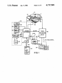
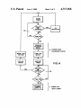
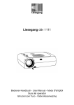
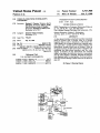
FIG. 1 is a block diagram showing a video disk player
The player is put into a quiescent state according to
arranged according to the invention;
the invention upon receipt of a power-down signal
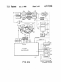
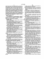
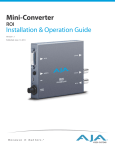
FIGS. 24 and 2b are diagrams elaborating in particu
PDN from a power-down program 50. The signal PDN
lar upon the system controller and signal processing
is generated after a timer 52 indicates the elapse of a
blocks shown by FIG. 1;
predetermined interval of time (the play interval) with
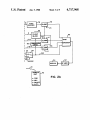
FIG. 3 is a diagram showing more detail of the sys
out the system processor 36 receiving any selections
tem controller; and
from the control unit 40 or instructions from the auto
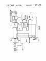
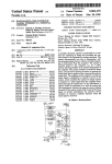
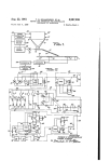
FIG. 4 is a functional flow diagram for a computer 15 matic playback section 38. Should the processor 36
program that may be used with the system controller of
FIGS. 1, 2 and 3 to place the player in a quiescent state.
receive a selection (or automatic instruction) before the
signal PDN is generated, it sends a reset signal RST to
restart the timer 52, which again starts counting from
the beginning of the play interval. The play interval is
DETAILED DESCRIPTION OF THE
PREFERRED EMBODIMENT
20 set to such a time, say ?ve minutes, that only in rare
FIG. 1 shows a general diagram of a video disk
situations would no selection (or instruction) be re
player incorporating a quiescent state and auxiliary
ceived while a user is actually viewing a set of pictures.
features according to the invention. A magnetic disk 10
Ordinarily, then, the quiescent state would never be
is attached by its hub 12 to a disk drive motor 14. A
invoked during use of the player, and the user would go
stepper motor 16 is connected by a reduction gear 18 to 25 through the pictures unaware of the continuously reset
a lead screw 20, which mates with a threaded hole 22 in
ting timer 52.
a non-rotatable head block 24. A playback head 26 is
mounted on the head block 24. The head block 24 is
supported for movement radially of the disk 10 so that
received during the play interval, and the power-down
On the other hand, if no selection (or instruction) is
signal PDN is generated, the system processor 36 inacti
the playback head 26 may be positioned in contact with 30 vates the drive motor 14 and sends the blanking signal
a selected track on the disk 10, such as a magnetic track
BLANK to the signal processing circuit 32. The signal
A.
BLANK instructs the signal processing circuit to enter
The player includes a system controller 30 (enclosed
its second mode and produce the second video signal, a
by broken lines) and a signal processing circuit 32. The
primary function of the player is to reproduce a play
back signal from the selected magnetic track A and to
generate from that a video signal suitable for displaying
a selected still picture (corresponding to the playback
picture blanking signal, for the display 34. Meanwhile
35 the drive motor 14 comes to a stop, the disk 10 there
with, and the head 26 no longer generates a playback
signal. Importantly, the head 26-though still adjacent
the surface of the disk 10-is no longer traversing the
track A and stressing, or even wearing away, the mag
tion, the signal processing circuit 32 operates in two 40 netic material. In addition, instead of showing an unap
~modes: in the ?rst mode the circuit 32 responds to the
pealing, noisy raster, the display 34 shows a blank
' signal) on a video display 34. For purposes of this inven
playback signal sensed by the playback head 26 and
produces a ?rst video signal for displaying the selected
(black) screen, or any other image desired (for example,
from a text generator).
still picture on the video display 34; in the second mode
Once the system processor 36 puts the player into the
it responds to a control signal (BLANK) and produces 45 quiescent state due to receipt of the power-down signal
a second video signal for displaying some predeter
PDN, the system processor 36 immediately sends the
mined image-normally that of a blank screen-in lieu
signal RST to restart the timer 52. The timer 52 pro
of the still picture. (The ?rst mode is depicted in FIG. 1
ceeds to count until a second predetermined interval of
by the display 34 being in solid line and its connection to
time (the quiescent interval) has elapsed. Should a selec
the circuit 32 also in solid line; the alternative second 50 tion from the control unit 40 (or an instruction from the
mode is shown by broken line, both as to the same
auto playback section 38) be received before the second
display 34 and its connection to the circuit 32.)
interval has elapsed, the system processor 36 energizes
The positioning of the head 26 in correspondence
the drive motor 14 and deactivates the blanking signal
with the selected track A and the rotation of the disk 10
BLANK. The circuit 32 then reverts to its ?rst mode
are controlled by the system controller 30. A system 55 during which its sends the first video signal to the dis
processor 36, residing in the system controller 30, re
play 34 and shows the selected still picture from the
sponds to selection instructions from an automatic play
track A. At the same time the timer 52 is reset and starts
back section 38 and from a control unit 40, which is the
counting again (toward the elapse of the play interval).
user interface with the player. The user turns the player
The quiescent interval is set to a suitably long time, say
on or off and controls the order of picture viewing (by
one hour, during which the user has an opportunity to
forward and reverse buttons) from the control unit 40.
resume viewing at the point of interruption.
As shown here, the control unit 40 emits a coded infra
If, however, the end of the quiescent interval is
red signal 42, which is received by an IR receiver 44
reached without receipt of a selection (or an instruc
and transmitted to the system processor 36. An arrange
tion), the player is put into a semi-powered shutdown in
ment for automatically viewing the pictures on the disk 65 which most, but not all, of the player is deenergized.
10, for example, as to the order or the time allotted for
For this reason a power supply 54 is provided having
displaying each picture, is entered via the control unit
. 40 to an instruction memory 46 in the automatic play
two powered modes: a playback mode and an off mode.
In the playback mode both power lines V and V’ are
5
4,717,968
6
to generate the luminance of each line of the interlaced
?eld. Ordinarily the chrominance for the interlaced
?eld is just a repeat of the recorded ?eld.
energized, providing power to the system controller 30
and to the signal processing circuit 32, thereby effecting
playback. The power supply 54 is put into the off mode
upon receipt of a disable signal P.EN from the system
processor 36 (after the quiescent interval has run out).
The power supply 54 responds to the signal P.EN by
Since the signal from the disk is line-sequential (that
is, a pair of color difference signals alternate from line to
line), it is necessary to store the color difference signal
from each line and repeat it for the next line so that both
deenergizing the line V, leaving energized only the
color difference signals are available for subsequent
power line V’. The energized line V’ is connected to the
processing. Such a store and repeat operation is per
receiver 44 and to the processor 36 to interpret and act
upon an on/off signal from the control unit 40 via the 10 formed by a chroma repeater 70. The color difference
signals R-Y and B-Y are then applied to respective
receiver 44. This means that all parts of the player are
clamps 72a and 72b for establishing appropriate dc lev
deenergized except those parts necessary to restart the
els. Meanwhile the tips of the synchronization portion
player if the on/off button is actuated from the control
of the luminance signal Y are clamped in a sync tip
unit 40.
clamp 74 and then clipped off the signal in a sync clip
The functional routine for putting the player into the
per 76 (an operation that is desirable for subsequent
quiescent state, and then into shutdown, is shown by the
encoding). The clipped luminance signal is then
?ow diagram of FIG. 4. For the example shown, the
clamped to an appropriate dc level in a clamp 78. As
?rst predetermined interval (play interval) is 5 minutes
will be shown, the clamps 72a, 72b and 78 operate on
and the second predetermined interval (quiescent inter
val) is 55 minutes. The timer 52 is shown in its preferred 20 their respective signals whether the player is receiving
a playback signal from the disk 10 or is in the quiescent
form as software timing routines 55 and 56. These tim
state (and the disk 10 is stopped).
ing routines are interrupted by a selection (or an instruc
A playback synchronization signal CS is provided by
tion) and the ?ow reverts back to the beginning of the
a synchronization separator 80 connected into the path
diagram. If 5 minutes run out before a new selection is
entered, the display is blanked and the drive motor 25 of the Y signal. Alternatively a synchronization signal
CS’ is locally-generated by a free-running sync genera
stops. Then, if 55 more minutes run out without any
tor 82 and used during the quiescent state to stabilize the
selection, the player is turned off. Thereafter, the player
picture on the display 34. Both sync signals are applied
only responds to the on/off selection from the control
to the input terminals of a switch 84; its output signal is
unit. However, any selection (forward, reverse, etc.)
other than “on/off” during the 55 minutes of the quies 30 a composite sync signal CSP necessary for proper gen
cent interval turns the drive motor on and returns the
eration of an NTSC encoded signal in an encoder 86.
last picture to the display. (Depressing the “on/off”
button puts the player into the semi-powered shutdown
mode.) The user, in effect, always picks up where view
ing left off regardless of the button pushed (except the 35
The switch 84 is operated according to the condition of
the signal BLANK (also described in connection with
FIG. 1) received from the system controller 30. The
“on/off’ button); thereafter the buttons resume their
normal functions and other pictures may be displayed.
84-whenever the head 26 is moving between tracks or
signal BLANK changes state-and toggles the switch
when the disk 10 is not rotating (the quiescent state).
This invention is especially concerned with the latter
occurrence. When the signal BLANK is high because
detailed diagram of the player, and in particular of the
signal processing circuit 32; FIG. 3 shows more detail 40 the motor 14 is off (or the head is between tracks) the
switch 84 conducts the locally-generated sync signal
of the system controller 30, which appears in both
CS’ through to the encoder 86 (as the playback sync
FIGS. 1 and 24. Components already discussed in con
signal CSP). At other times, when the signal BLANK is
nection with FIG. 1 are given like'numbered reference
low, the switch 84 conducts the playback synchroniza
characters. The playback signal generated by the play
back head 26 is, in the preferred embodiment, a low 45 tion signal CS through to the encoder 86 (as the play
back sync signal CSP).
level, line sequential fm signal which is provided to the
The clamps 72a, 72b and 78 operate concurrently
input terminals of a preampli?er and equalization circuit
with the proper sync signal to clamp the color differ
60. Rfequalization compensates for distortion present in
ence signals R-Y and B-Y and the luminance signal Y at
the output voltage from the playback head. The output
FIGS. 20 and b taken together are a generally more
voltage from the preampli?er and equalization circuit
50 correct dc levels for the encoder 86. The clamps are
operated at selected dc levels L1, L2 and L3 by clamp
and blank logic 88 during a substantial portion-prefer
ably all-of the horizontal drive interval. Since the sync
back signal. The separate Y and C signals are applied to
signals exist only for a short time at the beginning of the
respective limiters 64a and 64b in order to eliminate
amplitude ?uctuations. The limited Y and C fm signals 55 drive interval, a suitably long triggering pulse for the
logic 88 is generated from the sync signal CSP by a
are demodulated in respective circuits 66a and 66b,
horizontal drive generator 90. The logic 88 also needs
which also attenuate the higher frequencies (deempha
to recognize the presence of the 0.5 H delayed interlace
sis) according to the amount that they were intention
?eld in order to correctly time the clamps; this is done
ally boosted at recording. It should be recalled that the
by a signal F from the ?eld interlacer 68. The clamped
signal recorded on the disk 10 (track A) represents one
60 is fed to a separation ?lter 62 for separating the lumi
nance (Y) and chrominance (C) signals from the play
?eld of a television signal. In order to provide a full
frame signal, the demodulated Y and C signals are ap
plied to a ?eld interlacer 68. As is conventional, the
interlacer 68 internally switches between two signal
luminance and color difference signals are formulated
into an NTSC signal by the encoder 86 in relation to
timing information provided by the playback sync sig
nal CSP. The encoded video signal is converted into a
paths: one path directly passes the signals through for 65 radio frequency signal by an rf modulator 92 and sent to
the video display 34.
one ?eld; the other path includes a 0.5 H delay and
The player is controlled according to user demands
provides the interlaced ?eld. The luminance signal Y
by the system controller 30. User selections are entered
for adjacent lines of the recorded ?eld may be averaged
7
4,717,968
through the hand-held remote unit 40, which has its
own battery power source. The remote unit 40 includes
an infra-red transmitter, which generates a coded infra
8
enable the address latch 112 and the memory 102, re
spectively, for external data memory access and exter
nal program memory fetch operations. Each compo
nent of the system controller 30 is continuously pow
red signal IR that radiates through space to the receiver
44. The receiver 44 decodes the input signal IR and
provides the decoded user signal REM IN to the system
ered by the section 540 of the power supply 54, though
the remainder of the player may be deenergized. A
controller. Pursuant to the appropriate user command,
program of the type shown as a ?ow diagram in FIG. 4
the four motor phase signals (bl-$4 applied to the step
per motor 16 which accordingly steps through its posi
is stored in the program memory 102 for powering parts
of the player down (the drive motor 14) when in the
tions as directed. The lead screw 20 is turned and the 10 quiescent state and all of the player but the system con
head 26 is positioned adjacent a desired track (such as
the track A). Meanwhile, a signal M.EN provided to a
speed control circuit 94 starts the disk drive motor 14. A
troller 30 and the receiver 44 when in shutdown.
The player as thus far described assumes that the
drive motor 14 stops and the head 26 simply stays put in
tachometer circuit (not shown) monitors the motor
speed and, when operating speed is attained, a signal
the quiescent state (e.g., by providing only two of the
M.LOCK signi?es that the disk 10 is locked up at cor
ward for the signal processing circuit 32 to resume in
the ?rst mode (FIG. 1) when the motor 14 is restarted,
again showing the picture last seen on the display 34.
rect playback speed.
phase signals ‘DI-(1)4). This makes it quite straightfor
If the predetermined play interval passes without any
input from the remote unit 40, then the disk drive motor
However, it may be desirable to move the head to some
14 is deenergized by a signal M. STOP sent to the speed 20 parking position at the edge of the disk or to separate
control circuit 94 from the system controller 30. No
the head from the disk when the drive motor 14 and the
playback signal, consequently, is sensed by the head 26.
player sit in the quiescent state. In such a case, the mi
At the same time, the signal BLANK is emitted by the
croprocesser 100, which is normally monitoring track
controller 30 to the switch 84, toggling the switch so
locations anyhow, memorizes the location of the track
that the generated sync signal CS’ forms the signal CSP 25 A (i.e., track 1 or 2, etc. ) in its internal (or external)
sent to the encoder 86 (in lieu of the playback sync
memory. Then, if play is resumed within the quiescent
signal CS). The clamps 72a, 72b and 78 operate during
the horizontal drive interval (from the generator 90)
derived from the signal CSP (that is, the generated sync
signal CS’). Thus the generated sync signal CSP occurs 30
substantially at horizontal intervals, causing a stable
picture to appear on the display 34. With the horizontal
interval (55 minutes) the microprocessor 100 will call
for this track location and signal the stepper motor 16 to
move the head 26 back to the track it was before play
back was interrupted.
The preceding disclosure of the operation of the sys
tem controller 30 constitutes a sufficient speci?cation of
the operating software for putting the player in or out of
drive interval of each signal clamped to black by virtue
of the clamps 72a, 72b and 78, and with no video signal
the quiescent state and shutdown, and for accomplish
coming from the ?eld interlacer 68, the video portion of 35 ing ancillary activities (starting and restarting a timing
the clamped signals remains at a black level and pro
routine, producing the blanking signal, providing the
vides a dark, blank picture on the display 34. The sys
stepper motor phase signals, controlling the disk drive
tem controller, in the meantime, starts timing out the
motor, and the like). A programmer of ordinary skill
predetermined quiescent interval. If the quiescent inter
can, from this speci?cation, develop the program code
val passes without any user input from the remote unit
to accomplish the stated operation without engaging in
v40, then the signal P.EN to the power supply 54
any undue experimentation or effort.
changes state and causes the power supply 54 to deener
The invention has been described in detail with par
gize the section 54b producing the supply voltage V.
ticular reference to a presently preferred embodiment,
This deenergizes the portion of the player devoted to
but it will be understood that variations and modi?ca
signal processing and to the drive system. The system 45 tions can be effected within the spirit and scope of the
controller 30 remains powered from the supply section
invention. For example, while video apparatus accord
540, which provides the supply voltage V’.
ing to the invention has been described in connection
The system controller 30 is shown in greater detail in
FIG. 3. A microprocessor 100 (such as an Intel 8031
with a player, it may also be described in connection
with a video still camera that utilizes a similar type of
microprocessor) provides the central processing capa
magnetic disk. Though the picture recording takes
bility. Operating programs for the player are stored in a
program memory (ROM) 102. Input data is received
place during one passage of the camera’s recording
from the player directly by the microprocessor 100 and
head over a circular track on the disk, the head will
repetitively pass over the same circular area prior to
by an input buffer 104. Output data is provided to the
player by a latch 106 (and could also be provided di
cent timer is set when the camera is turned on. Then, if
rectly by the microprocessor 100). The four phase sig
the camera’s shutter is not released in, say 5 minutes the
nals (Pl-Q4 to the stepper motor 16 are generated by a
camera enters a quiescent state to minimize disk wear
(and to conserve energy. since the camera runs off bat
driver 108 pursuant to instructions relayed from the
microprocessor 100 through the latch 106. Addresses
taking the picture. According to the invention, a quies
tery power). The power-consuming part of the camera’s
and data are moved back and forth through a bus struc= 60 electronics, as well as a disk motor, are inactivated. The
ture 110. Memory instructions are accessed by ad
recording head remains in the recording position and
dresses latched off the bus 110 by an address latch 112.
certain parts of the electronics (e. g., a microprocessor)
The system controller components are each enabled by
remain powered in order to receive and process a “reac
respective lines tied to the microprocessor 100. More
tivate” signal. A partial depression of the shutter button
particularly, the read and write enable lines RD and 65 restores the camera to full operation and the quiescent
WR connect to the buffer 104 and the latch 106, respec
timer is reset (e.g., to 5 minutes). Alternatively, if the
tively, for read and write operations. The address en
shutter button was not depressed for, say, 30 minutes,
able ALE and the program store enable line PSEN
the quiescent state is terminated and the camera is com
9
4,717,968
10
controller means for receiving and processing in
structions from said control unit;
signal processing means responsive to said playback
signal for generating a video signal suitable for
displaying said selected still picture on the video
pletely inactivated. The recording head is retracted to a
home position (relative the edge of the disk) and all of
the electronics is shut off. The user must reactivate a
main power switch to use the camera again. The camera
therefore utilizes elements of the invention, that is, the
display;
automatic entry of a quiescent state after a ?rst time
a power supply for selectively energizing said con
troller means and said signal processing means;
means responsive to the elapse of said predetermined
interval for initiating a further predetermined inter
interval and ‘the automatic termination of the quiescent
state and inactivation of the apparatus after a second
time interval in the quiescent state. The camera also
includes the important option of easily terminating the
val;
quiescent state (by instructions from a control unit, such
as a shutter) and reactivating the apparatus anytime
during the second interval.
What is claimed is:
means for generating a second power-down signal
after said further predetermined interval has
elapsed; and
means responsive to said second power-down signal
for inactivating only the part of said power supply
that energizes said signal processing means.
1. Video apparatus for processing signals represent
ing still pictures, said apparatus utilizing a magnetic
medium on which the signals are recorded on recircu
5. A video player for producing still pictures on a
video display from signals recorded on circular tracks
a magnetic head;
means for positioning said magnetic head in contact 20 on a magnetic medium, said player comprising:
a playback head for sensing the signals recorded on
with a selected track;
lating tracks, said apparatus comprising:
the medium;
a control unit for entering instructions to the appara
tus regarding the processing of the signals;
means for supporting the medium for rotation relative
to said magnetic head so that said head repeatedly
passes a selected track;
means for generating a ?rst power-down signal after
a ?rst predetermined interval has elapsed without
any instructions from said control unit;
30
means responsive to said ?rst power-down signal for
arresting said rotation of the medium;
means for generating a second power-down signal
after a further predetermined interval has elapsed
means responsive to an instruction entered through
said control unit during said further predetermined
interval for resuming rotation of the medium;
a timer for counting out said ?rst interval; and
means responsive to resumed rotation of the medium
for resetting said timer to again start counting said 45
?rst interval.
3. A video player for producing still pictures on a
video display from signals recorded on circular tracks
on a magnetic medium, said player comprising:
a playback head for sensing the signals recorded on 50
'
means for positioning said playback head in contact
with a selected circular track;
a control unit for entering user selections to the
55
means for supporting the medium for rotation relative
to said playback head so that said head repeatedly
senses a selected track and accordingly generates a
playback signal representative of a selected still
picture;
means for generating a power-down signal after a
predetermined interval has elapsed without any
selections from said control unit; and
means responsive to said power‘down signal for ar
resting said rotation of the medium and discontin 65
uing generation of said playback signal.
prising:
drive means for moving the medium relative to said
playback head so that said head repeatedly tra
verses a selected track and accordingly generates a
signal processing means responsive in a ?rst mode to
said playback signal for generating a ?rst video
signal suitable for displaying said selected still pic
ture on the video display and in a second mode for
2. Video apparatus as claimed in claim 1 further com
4. A video player as claimed in claim 3 further com
player, particularly selections directed to said head
positioning means and indicating the identity of the
selected track;
picture;
prising:
player regarding selected tracks;
a control unit for entering user selections to the
playback signal representative of a selected still
following said ?rst interval; and
35
means responsive to said second power-down signal
for inactivating the apparatus.
the medium;
means for positioning said playback head in contact
with a selected circular track;
generating a second video signal suitable for dis
playing a predetermined image on the video dis
play in lieu of said selected still picture;
means for generating a power-down signal after a
predetermined interval has elapsed without any
selections from said control unit;
means responsive to said power-down signal for inac
tivating said drive means, thereby arresting said
relative movement, and for instructing said signal
processing means to enter said second mode and
route the second video signal to the display; and
means responsive to a selection entered through said
control unit for reactivating said drive means and
for instructing said signal processing means to
route the ?rst video signal to the display.
6. A player as claimed in claim 5 further comprising:
a receiver for detecting selections entered into the
control unit;
a power supply operative in a playback mode for
energizing the player to effect playback and in an
off mode for enabling the receiver to detect at least
certain selections from said control unit;
means responsive to said ?rst power-down signal for
generating a second power-down signal after a
further predetermined interval has elapsed without
any selections from said control unit; and
means responsive to said second power-down signal
for inactivating said power supply by placing it in
said second mode.
7. A player as claimed in claim 5 further comprising:
11
4,717,968
a memory for storing prearranged instructions which
are optionally provided in lieu of selections from
said control unit;
with a selected track on the disk;
means for generating a ?rst synchronizing signal
referenced to said playback signal and a second
synchronizing signal from a free-running sync gen=
erator;
means for automatically directing said positioning
means to move from track to track according to
said prearranged instructions; and
said means for generating a power-down signal addi
tionally generates said power-down signal after a
predetermined interval has elapsed without receiv—
ing any prearranged instructions.
12
means for positioning the playback head in contact
10
signal processing means responsive to said playback
signal and to said ?rst synchronizing signal for
generating a video display signal for reproducing a
picture on the display device;
8. In a video disk player capable of cycling between
a remote control unit for communicating user track
a powered state and a semi-powered shutdown, the
powered state one in which (a) a magnetic disk is sup
ported for rotation in contact with a playback head for
reproducing a playback signal from a track on the disk
according to instructions from a control unit and (b) a
selections to the player;
means for receiving said selections from said remote
control unit and utilizing them to control said posi
tioning means;
means for generating a power-down signal after a
video picture signal is generated from the playback
signal for operating a display, the semi-powered shut
down being a condition in which the player is capable
predetermined time interval has elapsed without
of processing at least some instructions from the control 20
unit, particularly instructions to return the player to the
powered state, the improvement of a quiescent state in
which the player further comprises:
means for generating a power-down signal after a
predetermined time interval has elapsed in the
25
powered state without any instructions from said
control unit;
means responsive to said power-down signal for initi
ating the quiescent state by arresting movement of
the disk relative to the head and by replacing the
video picture signal with a blanking signal for
synchronizing signal, said signal processing means
then substituting a picture blanking signal in lieu of
said display signal; and
means responsive to a selection from said control unit
for actuating said disk drive motor and regenerat
ing the display signal.
13. A video disk player for reproducing still pictures
30 on a video display from a composite color video signal
recorded as one ?eld per circular track on a. ?exible
magnetic disk having many such tracks, said player
comprising:
blanking the display; and
a playback head for sensing the composite signal
means responsive to an instruction from the control
unit during the quiescent state for resuming move 35
ment of the disk relative to the head and for return
ing the playback signal to the display.
recorded on the disk;
means for urging said playback head into physical
contact with a selected track on the disk;
9. A player as claimed in claim 8 further comprising
means operative in the quiescent state for generating a
second power-down signal after a further predeter
means for supporting the magnetic disk for rotation
relative to said head, said supporting means includ
ing a drive motor for rotating the disk;
means for separating luminance and chrominance
mined interval has elapsed without receiving any in
structions from the control unit; and means responsive
to said second power-down signal for putting the player
into shutdown.
10. A player as claimed in claim 8 further including
an automatic display facility responsive to prearranged
instructions which are optionally provided in lieu of
signals from the composite signal;
means for separating a synchronizing component
from said luminance signal;
means for generating a substitute synchronizing com
ponent;
signal processing means responsive to said separated
synchronizing component for generating a video
instructions from the operator control unit, said means
for generating a power-down signal therefore generat
ing said signal after either a predetermined interval has
elapsed without receiving any instructions from the
any selections from said receiving means;
means responsive to said power-down signal for de
energizing said disk drive motor and for replacing
said ?rst synchronizing signal with said second
display signal from input signals derived from said
timing means for counting through said predetermined
luminance and chrominance separating means;
a system controller for operating the player accord
ing to externally-generated instructions, said con
troller generating a power-down signal after a pre
determined time interval has elapsed without re
ceipt of said external instructions;
means responsive to said power-down signal for inac
tivating said drive motor and for routing said sub
interval and for providing a timing signal at the end
thereof, and means responsive to said timing signal for
stitute synchronizing signal to said signal process
ing means in lieu of said separated synchronizing
50
control unit or a predetermined interval has elapsed
without receiving any prearranged instructions from
the automatic display facility.
11. A player as claimed in claim 8 in which said 55
means for generating a power-down signal comprises
generating said power-down signal°
60
12. A video disk player for reproducing pictures on a
video display from signals recorded on circular tracks
on a ?exible magnetic disk, said player comprising:
a playback head for sensing the signals recorded on
the disk and providing a playback signal;
65
a disk drive for supporting the magnetic disk for
rotation relative to said head, said disk drive in
cluding a drive motor for rapidly rotating the disk;
signal;
'
means responsive to said substitute synchronizing
signal for clamping the input signals to said signal
processing means to do levels corresponding to a
blank display; and
means responsive to the receipt of an external instruc
tion for reactivating said drive motor and for rer
outing said separated synchronizing signal to said
signal processing means.
4,717,968
-
14
13
means responsive to said ?rst power-down signal for
arresting said rotation of the medium;
means for generating a second power-down signal
after a further predetermined interval has elapsed
14. Imaging apparatus for recording signals repre
senting pictures on circular tracks on a magnetic me
dium, said apparatus comprising:
a recording head for recording the signals on the
following said ?rst interval; and
means responsive to said second power-down signal
for inactivating the apparatus.
15. Apparatus as claimed in claim 14 further compris
medium;
means for positioning said recording head in contact
with a selected circular track;
a control unit for entering user instructions to the
apparatus;
mg:
means responsive to an instruction entered through
means for supporting the medium for rotation relative
to said recording head so that said head repeatedly
passes a selected track and, when instructed by said
control unit, records the signals representative of a
said control unit during said further predetermined
interval for resuming said rotation of the medium;
selected still picture;
means for generating a ?rst power-down signal after 15
a ?rst predetermined interval has elapsed without
any instructions from said control unit;
25
35
45
50
55
65
a timer for counting out said ?rst interval; and
means responsive to resumed rotation of the medium
for resetting said timer to again start counting said
?rst interval.
*
i
i
*
i