1
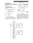
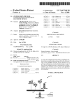
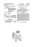
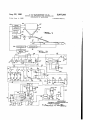
Aug. 22, 1961
T. R. SCHUERGER ET AL
Filed June 4, 1958
2,997,205
METHOD AND APPARATUS FOR CONTROLLING
DISCHARGE OF MATERIALS
2 Sheets-Sheet l
!
20
23\ speed
22
A
3”
——compuling
2/
circa/‘l
'
3"
1
1
memory
device
‘
-
1
motor
control
za?trronsducerH sumniofor I:
+
I
/
55 ’ amp.
27
By
Aug. 22, 1961
T. R. SCHUERGER ETAL
2,997,205
METHOD AND APPARATUS FOR CONTROLLING
DISCHARGE OF MATERIALS
Filed June 4, 1958
-
dc.
2 Shee‘ts-Sheet 2
TE: 3
E
30
56
l0 m0/0r32
D,
0
FIG? 4
-
75
"
TIMER 70 "
?'
'
"01v TIME"
A
‘
"0FF TIME”
"01v TIME "
TIME‘? 7/ __[ ——-—--s
TIME/i’ 72
A-——---——--— ----- 'oFF r/MF"
—_¢
—- "01v TIME"
I
——
_-
-N
TIMER 73
"oFF T/MF”
"am TIME”
"OFF TIME ”
IN VE/V TOPS
THOMAS H. SCHUERG‘ER and
FRANK SLAM/U?
5!
Altar/1 ey
,.
United grates Patent 0 ” 1C@
1
2,997,205
Patented Aug. 22, 1961
2
a portion of a sinter feed compounding apparatus equipped
2,997,205
METHOD AND APPARATUS FOR ‘CONTROLLING
DISCHARGE 0F MATEREALS
Thomas R. Schuerger and Frank ‘Slamar, Monroeville,
Pa., assignors to United States Steel ‘Corporation, a
corporation of New Jersey
Filed June 4, 1958, Ser. No. 739,870
'18 ‘Claims. (Cl.222--1)
with a control mechanism in accordance with our inven
tion;
FIGURE 2 is a schematic wiring diagram of a speed
computing circuit, calibration device, memory device and
motor control embodied in our control mechanism;
FIGURE 3 is a schematic wiring diagram of a timer
circuit embodied in our mechanism; and
FIGURE 4 is a graph showing the operating sequence.
This invention relates to an improved mechanism and 10
FIGURE 1 shows a portion of a sinter feed compound
method for controlling discharge of material from a bin
ing apparatus similar to that of the aforesaid earlier ap
or the like.
plication. The portion shown includes the discharge end
An earlier application of the present co-inventor
of a main conveyor belt 10 carrying a bed of material M,
Schuerger Serial No. 579,326, ?led April 19, 1956, now
a bin 12 supported above the belt and containing hot
abandoned, discloses an apparatus and method for auto
matic proportioning of ingredients of a sinter feed ap
15 recycle R, a table feeder 13 at the bin discharge, and a
vibratory conveyor 14 carrying hot recycle from the
plicable especially to iron ore. (A continuation-in-part of
table feeder to the ‘belt. A variable speed D.-C. motor
the earlier application issued as Patent No. 2,980,291,
15 drives the table feeder, and the quantity of hot recycle
April 18, 1961). The apparatus includes a main con
discharged from the bin is a function of the speed of
veyor belt, a series of bins located above the belt and 20 this motor. The material M consists of ore (for ex
containing the individual ingredients, and table feeders
for feeding these ingredients in controlled quantities to
the belt. Several bins nearest the feed end of the belt
contain ore ?nes and equivalents. The next bins con
ample iron ore) and additives previously fed to the belt,
and protects the belt from direct contact with hot re
cycle, which commonly is at a temperature su?icient to
burn the belt. The belt runs over a ?rst belt scale 16
tain additives, such as coke and anthracite ?nes, ?ue dust 25 immediately before hot recycle feeds thereto and a second
and sized returns. The bin nearest the discharge end of
belt scale 17 immediately after. The difference in weight
the belt contains hot ?nes returned from the sintering ma
registered by these scales represents the actual weight of
chine for recycling. These ?nes, known as “hot recycle,”
'hot recycle reaching the ‘belt. The scales transmit signals
‘ are another equivalent of ore and must be used approxi
to a summator 18, which continuously computes this dif
rnately as received, except that the bin allows sui?cient 30 ference. The scales and summator can be similar to cor
surge capacity to permit their feeding to the belt at uni
responding parts in the earlier application; hence they
form rates for reasonable periods. The invention claimed
are shown only in block diagram in the present applica
in the earlier application concerns a control for auto
tion. Material discharging from the belt is moistened,
matically proportioning additives in accordance with com
mixed in a pug mill, and sintered as in the earlier ap
bined weight of ore and hot recycle, even though hot 35 plication.
recycle reaches the ‘belt after the additives. The mech
Bin 12 is equipped with a device for sensing the level of
anism and method of the present invention are particu
hot recycle therein. The preferred sensing device in
larly suited for controlling the discharge of hot recycle
cludes lower and upper radiation-sensitive “Ohmart” cells
from its bin to the main conveyor in a system like that
shown in the earlier application. Nevertheless the in
19 and 20 mounted on an outside wall of the bin and cor
responding radiation sources- 21 and 22 mounted on the
vention is not thus limited, but may be applied else
where to overcome analogous problems.
An object of the present invention is to provide an
improved mechanism and method for controlling dis
opposite outside wall. The lower cell 19 ‘and radiation
source 21 de?ne the lower limit of the predetermined
range within which the hot recycle level is maintained,
and the upper cell 2t) and radiation source 22 the upper
charge of material ‘from a bin or the like to hold the 45 limit. When radiation from either radiation source passes
level of material in the bin within a predetermined range.
through material in the bin' before reaching the corre
A further object is to provide an improved mecha
nism and method for controlling discharge of material
from a bin by sensing whether the level of material in
the bin is within a predetermined range and, if out of
sponding cell, the quantity of radiation reaching the cell
is at a minimum. As known in the art, each cell may
be compensated by a second cell connected in opposition
(not shown) so that the cell transmits no signal when
this range, periodically changing the discharge rate by
receiving minimum radiation. This device has the ad
increments ?rst to return the level to the range and
thereafter to hold it within the range.
A more speci?c object is to provide an improved mech
vantage that it eliminates any need for mechanical con
tacts or probes within the bin where they are easily
damaged; otherwise a mechanical device would be large
control by changing the discharge rate by both a tem
porary increment to return the level to the predetermined
range and a permanent increment to hold it in this range.
predetermined range, only cell 20 transmits va signal.
When the level is too low, both cells transmit signals;
when too high, neither transmits a signal. The cells
anism and method which afford the foregoing type of 55 ly equivalent. When the hot recycle level is within the
A further object is to provide the foregoing type of
and radiation sources are not shown in detail, since suit
control, but to delay changes until compensating changes 60 able devices are known and available commercially.
are made elsewhere, for example in an apparatus for
compounding sinter feed, to delay changes in hot recycle
Nevertheless reference may be made to Ohmart Patent
No. 2,763,790 for a detailed showing of one such ar
rangement.
The cells 19 and 20‘ of the sensing device transmit sig
A further object is to provide the foregoing type of 65 nals to a periodically acting speed computing circuit 23.
discharge rate until the ore feed rate has been changed
inversely.
control, and to include means for periodically and auto
matically calibrating the mechanism.
In accomplishing these and other objects of the inven
tion, we have provided improved details of structure, a
preferred form of which is shown in the accompanying
drawings, in which:
FIGURE 1 is a diagrammatic side elevational view of
If the level is outside the predetermined range when the
circuit acts, the discharge rate from the bin should be
changed, and circuit 23 computes a new speed for motor
15 to effect such change. This new speed equals the alge
braic sum of the instant speed, a temporary increment
to bring the level back to the predetermined range, and
a permanent increment to hold it in this range. Both
2,997,205
.
~
,
a
3
4
increments are‘ of course negative when the level is too
low and positive when too high; If the level'returns
is too low, both contacts 19a and 20a open and both
relays A and B ‘are deenergized. When the level is within
the predetermined range, contacts 19a close and relay A
picks up. When the level is too high, both contacts 19a
and 20a close and both relays pick up.
Relays A and B control a pair of relays C and D, which
in turn control the application of negative and positive
from outside the range to within the range, when the cir
cuit again acts, it computes another new speed which
equals the instant speed with the temporary increment
discontinued. Circuit 23 transmits a signal representative
of the most recently computed speed for motor 15 to a
calibration device 24 and to a memory device '25. If the
speed computed for the next period is the same as for the
temporary speed change increments respectively. The
coil of relay C is connected across lines 30 and 31 in
present speed, this’ signal merely remains constant. The 10 series with back contacts A1 of relay A and front contacts
circuit 23, calibration device 24 and memory device 25
are shown only in block diagram in FIGURE 1, but are
shown more completely in FIGURE 2 and described in
E1 of a relay E of the timer circuit. Similarly the coil
of relay D is connected across these lines in series with
front contacts B1 of relay B and front contacts E2 of
relay B. As hereinafter explained, relay E automatically
The calibration device 24 also receives a signal from 15 and periodically picks up for brief intervals. If the level
more detail hereinafter.
the summator 18 representative of the actual weight of
hot recycle feeding to belt 10. Even though the motor
speed may remain constant, the weight may vary slightly
due to such factors as changes in characteristics of the
hot recycle or wear of the parts. Since the summator
commonly is a pneumatic pressure device and the cali
bration device is electric, a transducer 26 can be inter
posed between the two to convert the pressure signal to
in the bin is within the predetermined range when relay E
picks up, neither relay C nor D picks up, since both con
tacts A1 and B1 remain open. If the level is too low,
relay C picks up with relay E, since relay A is deener
gized and its contacts A1 closed. Similarly if the level
is too high, relay D picks up with relay E since relay B
is energized and its contacts B1 closed. Whenever either
relay C or D picks up, it seals in via back contacts E3 or
E4 of relay E and its own front contacts C1 or D1. Relays
a proportionate electric signal. The calibration device
transmits a signal representative of the weight of hot re 25 C and D are relatively slow-acting to enable them to re
main energized during the interval contacts E1 and E2 are
cycle to be fed at the most recently computed motor speed
opening and contacts E3 and E4 closing. After a tem—
through a line 27 to a suitable device, not shown, for
porary increment in the discharge rate returns the level
computing the combined weights of ore and hot recycle
feeding to the belt. Consequently a compensating change
to the predetermined range, contacts A1 or B1 immediately
open. The next time relay E picks ‘up and opens its con
can be made in the ore feed rate either if a change in
tacts E3 or E4, relay C or D drops out and the temporary
the speed of motor 15 is to be made or if there is a change
increment is discontinued.
in the weight of hot recycle feeding at the present speed.
Relays A and B also control a reversing motor 32 which i
The transducer 26 is not shown in detail, since devicm
in turn controls the application of permanent speed
suitable for this purpose are known and available com
mercially. Nevertheless reference can be made to Carl 35 change increments. This motor is connected across lines
30 and 31 in series with back contacts A2 and A3 of relay
son Patent No. 2,059,549 for a detailed showing of one
such device. The device which receives the signal from
A and front contacts E5 and E6 of relay E ‘for energizing
it in one direction, and in series with front contacts B2
to corresponding parts shown in the earlier application;
and B3 of relay B and the same contacts E5 and E6 for
hence their showing is not repeated. If needed, an elec 4:0 energizing it in the opposite direction. If the level is
within the predetermined range when relay E picks up,
tric-to-pneumatic transducer can be used to convert the
the motor does not operate, since contacts A2, A3, B2 and
electric signal from the calibration device to a pressure
line 27 and the parts associated therewith can be similar
signal for use in these parts. For a showing of a device
suitable for this last purpose reference can be made to a
B3 are all open. If the level is too low, the motor runs
in a direction to apply a negative increment, since relay
A is deenergized and contacts A2 and A3 are closed.
publication by the Foxboro Company, Foxboro, Massa
Similarly if the level is too high, the motor runs in the
chusetts, Bulletin 20-16 entitled “EMF Pneumatic Trans
opposite direction to apply a positive increment, since
mitter.”
relay B is energized and contacts B2 and B3 are closed.
When circuit 23 computes a new speed for motor 15
In either event the motor stops when relay E drops out
di?erent from the instant speed, the memory device 25
retains the instant speed until compensating changes are
and opens its contacts E5 and E5, thus limiting the mag
made in the ore feed rate and until belt lit travels a 50 nitude of the permanent increment.
The circuit includes a potentiometer 33 whose slide
sufficient distance that the altered portion of ‘bed M reaches
wire is connected to a suitable D.-C. source for develop~
the discharge end of vibratory conveyor 14. At the proper
ing a speed controlling voltage. The potentiometer has
moment the signal from circuit 23 representative of the
an arm 34 which is electrically connected to an output
newly computed speed acts on the memory device. There~
upon the memory device transmits this signal to a motor
terminal 35 via two variable resistances 36 and 37 in
series, and is mechanically connected to motor 32. Back
control 28, which changes the speed of motor 15 to the
contacts C2 of relay C are connected in parallel with
newly computed speed. This speed (including any tem
a portion of resistance 36 and thus normally shunt out
porary increments) is held until the cycle repeats. The
this portion of the resistance. When relay C picks up
motor control is shown only in block diagram in FIGURE
1, but is shown more completely in FIGURE 2 and de 60 as a result of a low level of material in the bin, contacts
C2 open and place the entire resistance 36 in series with
scribed in more detail hereinafter.
arm 34 and terminal 35. Consequently the voltage
Speed computing circuit
transmitted to the terminal drops to effect a negative
FIGURE 2 shows our speed computing circuit 23 more
temporary speed increment. Front contacts D2 are con
completely, but omits the applicable portion of the timer 65 nected in parallel with a portion of resistance 37. When
circuit shown separately in FIGURE 3. Circuit 23 is
relay D picks up as a result of a high level of material
energized through lines 30 and 31 connected to a suitable
in the bin, contacts D2 close and shunt out a portion of
D.-C. source. Cell 19 or its mechanical equivalent con
trols contacts 19a which are connected across these lines
in series with the coil of a relay A. Cell 20‘ or its me
chanical equivalent controls contacts 26a which are con
nected across the lines in series with the coil of a relay B.
In each instance the contacts open when the correspond
ing cell transmits a signal, and close when material in bin
12 outs oif the signal. Thus when the level of material
the resistance in series with arm 34 and terminal 35.
Consequently the voltage transmitted to the terminal
rises to e?ect a positive temporary speed increment.
The magnitude of temporary increments can be adjusted
by adjusting resistances 36 and 37. When motor 32
runs, it moves arm 34 along the slide wire in a direc
tion to lower or raise the voltage transmitted to the
terminal to e?ect a negative, or a positive permanent
2,997,205
speed increment. The magnitude of permanent incre
3
servomotor.‘ Periodically relay F picks up for a de?nite
ments can be adjusted by adjusting the length of time
interval and then drops out. The ampli?er 44 and servo
the motor runs. The ultimate voltage on the output
motor are energized for this interval and deenergized at
terminal 35 is proportionate to the most recently com
its conclusion.
puted speed for motor 15 and is transmitted to both the
The action of the integrator can be explained mathe
calibration device 24 and memory device 25. This volt
matically as follows:
age remains constant from the moment it is set until the
Let
next time relay E picks up, and even then remains con
e1 represent the input voltage to the ampli?er propor
stant unless a speed change is needed.
tionate to the weight of hot recycle;
10
Calibration device
e2 represent the input voltage to the ampli?er derived
from the tachometer-generator;
FIGURE 2 also shows the calibration device 24 more
completely, but again omits the applicable portion of
t represent the time interval the servomotor runs for
each calibration;
the timer circuit shown separately in FIGURE 3. The
calibration device includes a potentiometer 40 whose 15 x represent the number of revolutions of the tachometer
generator during the time t.
slide wire is electrically connected to terminal 35 of the
speed computing~ circuit, whereby the voltage applied
Then
to the slide wire is proportionate to the most recently
(92-61) is the effective voltage which tends to drive the
computed speed of motor 15. The potentiometer has
servomotor; and
an arm 41, which is mechanically connected to a cali 20
brating servomotor 42 and electrically connected with
gis the angular velocity of the tachometer-generator.
line 27. As hereinafter explained, the servomotor sets
the arm 41 in accordance with a proportionality factor
representative of the Weight of hot recycle which has
been feeding. When the voltage transmitted from the 25
output terminal 35 changes, line 27 immediately trans
mits a voltage proportionate to the weight of hot recycle
to be fed at the new motor speed, assuming any imme
e2=K-%
(e2— el) = 151%‘;
diate change inthe rate of feeding is directly propor
tional to the change in motor speed, that is, a constant 30
K?-— =Kliidig
The calibration device includes an integrator 43, which
computes an average rate of feeding for a portion of
the period after the memory device 25 and motor con
e1: (Ir-Keg
proportionality factor.
1
trol 28 have operated but before the next operation 35
of the speed computing circuit 23, and thus eliminates
any effect of minor ?uctuations in the rate of feeding
at any given motor speed. The integrator comprises an
Thus it is seen that x is a function of e1, and measure
electronic conversion ampli?er 44, a servomotor 45, and
a tachometer-generator 46. The ampli?er has the char 40 ment of x over a de?nite time interval can be used to
obtain an average value of e1 or the average rate at
acteristic that it energizes the servomotor in the appro
which hot recycle feeds for the same interval.
priate direction whenever its input terminals are at dif
The tachometer-generator is mechanically connected
ferent voltages, but stops the servomotor when they are
at the same voltage.
The ampli?er per se is a known
device and hence has been shown only in block form,
to the arm 49 of a potentiometer 50- through suitable
reduction gearing. At the beginning of a calibration
but reference can be made to Wills Patent No. 2,423,540 45 cycle the arm is at a zero or grounded position. The
distance the arm travels from this position during time
for a complete showing of a suitable ampli?er of this
type. A suitable ampli?er is available commercially
interval 1‘ furnishes a measure of the number of revolu
from Minneapolis-Honeywell Regulator Company under
tions x during this interval. The slide wire of poten
tiometer 50 is electrically connected to a suitable D.-C.
voltage source, whereby arm 49 transmits a voltage pro
portionate to the average rate at which hot recycle has
the trade name “Electronik,” No. 356,358 and is de
scribed in a printed publication by the manufacturer
entitled “Service Manual 15019M for Class 15 ‘Elec
fed during the interval 2‘.
‘
tronik’ Instruments” issue 8 (1956). The servomotor
After the computed rate has been utilized to set the
is a two-phase A.-C. induction motor which has the
potentiometer arm 41, as hereinafter explained, the
characteristic that under transient conditions its speed
varies with the voltage applied to its ?eld. We have not 55 potentiometer arm 49 is reset to its‘ zero position. For
this purpose the connection between transducer 26 and
described the motor in detail since it likewise is a known
the ?rst input terminal of ampli?er 44 contains contacts
device, but for a complete description reference can be
G1, and the connection between the generator 46 and the
made to Thaler and Brown “Servomechanisms Analysis,”
other input terminal contains contacts G2, which contacts
copyright 1953 by McGraw-Hill Book Company, Inc.,
60 are in a relay G of the timer circuit and are closed while
pages 63 and 391.
the integrator is averaging the feed rate. Contacts G3
The ampli?er 44 and servomotor 45 are electrically
of relay G ‘are adapted to connect the ?rst input terminal
connected to a suitable A.-C. source 47 which contains
to a ground 51. Contacts G; of relay G are adapted to
front contacts F1 of a relay F of the timer circuit in
connect the other input terminal to arm 49 of the potenti
series with the servomotor. One input terminal of the
ampli?er is electrically connected to the transducer 26, 65 ometer 50. Additional contacts G5 of relay G are adapted
whereby the voltage applied to this terminal is propor
tionate to the Weight of hot recycle feeding to belt 10,
but subject to minor ?uctuations. The other input ter
to connect servomotor 45 to the A.~C. source 47, bypass
ing the contacts F1. Contacts G3, G4 and G5 are open
While the integrator is averaging the feed rate. When the
potentiometer arm is to be reset, relay G picks up, where
minal of the ampli?er is electrically connected to one
of the output terminals of the tachometer-generator 46, 70 upon contacts G1 and G2 open and contacts G3, G4 and
whereby the voltage applied to the latter terminal is pro
G5 close. The servomotor 45 runs rapidly in the reverse
direction until the voltages applied to the two input ter
portionate to the generator output. The voltages applied
'to the two input terminals are of like polarity, but the
minals of the ampli?er 44 are equal. Since one terminal
latter is smaller. The output terminals of the ampli?er
is grounded at 51, these voltages become equal when the
.are electrically connected to a ?eld winding 48 of the 75 other terminal is grounded, that is, when the potentiom~
2,997,205
‘eter arm :49 reaches its zero setting. The integrator in
elfect becomes a null-seeking device while it is resetting
generator 65 and a magnetic ampli?er 66 which has a
‘the arm.
portion of the motor-generator vare connected to suitable
A.-‘C. sources. Arm 63 of potentiometer 62 is electrical
Another electronic conversion ampli?er 55 controls
the servomotor 42 which periodically sets the potenti
ometer arm 4-1 in accordance with the proportionality
factor. This ampli?er can be of similar construction to
control winding 67. The magnetic ‘ampli?er and motor
‘ly connected to the winding 67 and continuously transmits
thereto a voltage proportionate to the most recently ap
plied speed for motor 15. The magnetic ampli?er is
‘connected to a ?eld winding 68 of the D.-C. generator,
that used in the integrator. One input terminal of
whereby the voltage applied to the ?eld winding, and
ampli?er 55 is electrically connected to the potentiom
eter arm 49, whereby the voltage applied to this terminal 10 hence the voltage output of the generator, vary with the
voltage applied to the control winding 67. The genera
is proportionate to the average .rate of feeding just com
tor is electrically connected to the D.-C. motor :15, whose
puted by the integrator. The other input terminal is
speed thus is governed by this same voltage. We have
electrically connected to the slide wire 41. The output
not described the magnetic ampli?er in detail since it is
terminals of the ampli?er are connected to a ?eld vwinding
56 of servomotor 42. The ampli?er and servomotor are 15 a known device, but for a complete description reference
can be made to Storm “Magnetic Ampli?ers,” copyright
electrically connected to a suitable A.-C. source 57,
1955 by General Electric Company. An explanation of
which contains front contacts H1 of a relay H of the
timer circuit in series with the servomotor.
After arm
49 has been set, relay H picks up and energizes the ampli
the way a magnetic ampli?er can be used as a voltage
regulator for a D.-C. generator appears on pages 418 and
?er and servomotor, which runs until arm 41 reaches a 20 419 of this publication.
position along its slide wire such that the voltages ap
plied to the two terminals of the ‘ampli?er become equal.
Timer circuit
The usual condition is that the servomotor moves arm
FIGURE 3 is‘ a schematic wiring diagram of a preferred
41 only slightly if at all for each calibration. Any
timer circuit. In addition to the relays C, D, E, F, G and
voltage change on the slide wire of potentiometer 40 25 H already mentioned, this circuit includes another relay
already has produced a change both in the speed of motor
1 and four interval timers 70, 7-1, 72, and 73. These
15 and in the rate at which hot recycle is feeding before
timers are of a type which have an adjustable “off-time”
the integrator performs its computation, as explained
and an adjustable “on-time” that repeat as long as the
hereinafter in the description of the timer circuit. Conse
timer is running. Such timers per so are known and
quently the distance which arm 49 travels along its slide 30 are available commercially; ‘hence no detailed descrip
wire reflects this change in the feeding rate. A change in
tion is deemed necessary. However reference can be
the voltage applied to the second terminal of ampli?er
made to a printed publication of General Electric Com
55 by reason of a change in voltage applied to potenti
pany entitled “TSA-lS Industrial Interval Timer” for
ometer 4i} is largely compensated by arm 49‘ having
a complete showing and description. Relays C and D
reached a different position on its slide wire and thus 35 are energized from D.-C. lines 30 and 31 already men
applying a different voltage to the ?rst terminal.
tioned. The other relays and the timers are energized
from lines 74 and 75 connected to a suitable A.-C.
Memory device
FIGURE 2 also shows the memory device 25, again
source.
Timer 70' runs continuously and has contacts 70a and
omitting the applicable portion of the timer circuit. The 40 70b which open during its “o?-time” and close during its
memory device includes an electronic conversion ampli
tier 6%, a servomotor '61, and a potentiometer 62. The
ampli?er and servomotor are similar to corresponding
“on-time.” The “on-time” de?nes the interval during
which the speed computing circuit 23 computes a new
speed if such is needed. The “off-time” de?nes the inter
parts of the integrator. One input terminal of the ampli~
val between successive computations while the other ac
?er is electrically connected to the output terminal 35 45 tions take place. Contacts 70a and the coil of relay E
of the speed computing circuit 23, whereby the voltage
are connected in series across lines 74 and 75, and like
applied to this terminal is proportionate to the most
wise contacts 70b and the coil of relay J, whereby relays
recently computed speed for motor 15. The other
input terminal of the ampli?er is electrically connected
E and J pickup during the “on-time” and drop out during
the “off-time.” The way in which relay E controls relays
The slide wire of 50 C and D and motor 32 already has been explained in
to the arm 63 of potentiometer 62.
this potentiometer ‘is connected to a suitable D‘.'C. source,
whereby voltage applied to the terminal of the ampli?er
the descriptionof the speed computing circuit 263. Relay
I has three front contacts J1, J2 and I3 connected in series
respectively with timers 71, 72 and 73 across lines 74 and
wire. The ampli?er and servomotor are electrically con
75. These three timers do not run continuously like
nected to a suitable A.-C. source 64, which-contains front 55 timer 70, but are set to operate through only a single
contacts‘ Gs of relay G of the timer circuit in series with
cycle‘of “off-time" and “on-time” whenever they are en
the servomotor. As already mentioned, relay G also
ergized. Otherwise any errors in timer synchronization
controls resetting of the integrator 43 of the calibration
would be cumulative and would soon upset the operating
device 24. The servomotor 61 is mechanically connected
sequence. When relay J picks up, timers 71, 72 and 73
is proportionate to the position of arm 63 along the slide
to the potentiometer arm 63.
As already explained, changes in the ‘hot recycle dis
charge rate are delayed until compensating changes are
made in the ore feed rate. After relay E drops out and
60 are energized and go into “off-time.” These timers have
a second connection with line 75 via a conductor 76,
whereby they continue to operate through the remainder
of theircycles after relay I drops out.
after an appropriate delay for this purpose, relay G
After timer 70 shifts from “on-time” to “off-time,”
picks up and energizes the ampli?er 6t] and s'ervomotor 65 there is a delay during which all the timers are in “off
61, as well as resetting the integrator. If the voltage
time” to ‘allow any compensating changes in the ore feed
transmitted from terminal 35 to the ampli?er has changed
rate to be made and to allow conveyor 10 to travel a
since the preceding operation, the servomotor runs and
su?icient distance that 'such changes are re?ected in the
adjusts the potentiometer arm 63 until the voltage trans
bed of material M. Immediately following this delay,
mitted from potentiometer ‘62 to the ampli?er again 70 the “on-time” of timer 71 commences. This timer has
equals the ?rst voltage. Thereupon the servomotor stops
contacts 71a which open when the timer is not running
and relay G drops out until time for the next adjustment.
and during its “oif-time” and close during its “on-time.”
Contacts 71a are connected in series with the coil of re
Motor control
lay G across lines 74 and 75, whereby relay G picks up
The motor control 28 illustrated includes a motor 375 during the “on-time” .of timer 71 but otherwise drops out.
2,997,205
10
The way in which relay G controls operation of the
servomotor 6-1 to apply newly computed speeds to motor
15 already has been explained in the description of the
taining the level of material in a bin within a predeter
mined range. As applied to a compounding apparatus
for sinter feed, the invention coordinates any changes in
memory device. The way in which this relay controls re
the discharge of hot recycle with compensating changes
setting of the integrator 43 already has been explained in
which must take place. The control also provides for its
own automatic calibration. Most of the instruments used
are of standard manufacture and readily available com
the description of the calibration device. Timer 71 re
mains in “on-time” long enought for these steps to be com
pleted and then ceases to run for the remainder of the
merically.
cycle.
While we have shown and described only a single em
Next the “on-time” of timer 72 commences. This 10 bodiment of the invention, it is apparent that modi?ca
timer has contacts 72a which open when the timer is not
tions may arise. Therefore, we do not wish to be limited
running and during its “off-time” and close during its
to the disclosure set forth but only by the scope of the
“on-time.” Contacts 72a are connected in series with the
appended claims.
coil of relay F across lines 74 and 75, whereby relay F
1. The combination, with a bin adapted to contain
picks up during the “on-time” of timer 72 but otherwise 15 material to a level within a predetermined range, and a
drops out. The way in which relay F controls the inte
device for discharging material therefrom at a variable
grating action of the integrator 43‘ already has been ex
rate, of a control mechanism comprising means for sens
plained in the description of the calibration device. The
ing Whether the level of material in said bin is within or
“on-time” of timer 72 de?nes the interval it mentioned in
outside the range, and means operatively connected with
this description. It should be pointed out that timer 72 20 said sensing means and said discharging device and oper
allows the integrator to act during a period of the operat
able when the level is outside the range for periodically
ving cycle while no changes are taking place either in the
changing the discharge rate both by a temporary incre
ore feed rate or the hot recycle feed rate, and also that
the integrator acts for most of the period between suc
ment to return the level to the range and simultaneously
by a permanent increment to hold the level in the range
cessive operations of the speed computing circuit in order 25 after it has returned.
to furnish a truly representative proportionality factor.
2. The combination, with a bin adapted to contain
After integration is completed, timer 72 ceases to run.
material to a level within a predetermined range, and a
Next the “on-time” of timer 73 commences. This
variable speed device for discharging material there
timer has contacts 73a which open when the timer is not
from, of a control mechanism comprising means for
running and during its “off-time” and close during its 30 sensing whether the level is within or outside the range,
“on-time.” Contacts 73a are connected in series with the
and a speed computing circuit operatively connected with
coil of relay H across lines 74 and 75, whereby relay H
said sensing means and said discharging device and
picks up during the “on»time” of timer 73, but otherwise
operable when the level is outside the range to compute
drops out. The way in which relay H controls the servo
new speeds for the discharging device, the new speed
motor 42 to set the calibration device 24 already has been
including a temporary increment to return the level to the
explained in the description of the calibration device.
range and a permanent increment adapted to be applied
simultaneously with the temporary increment to hold the
level within the range after it has returned.
3. The combination, with a bin adapted to contain
Timer 73 remains in “on-time” long enough for this step
to be completed and then ceases to run for the remaining
moments of the cycle. Shortly thereafter the “on-time”
of timer 70 commences and the cycle repeats.
material to a level within a predetermined range, and a
Operating sequence
variable speed device for discharging material there
FIGURE 4 shows a typical sequence diagram for our
mechanism when applied to a sinter feed compounding
periodically ‘acting speed computing circuit operatively
apparatus. Initially timer 70, which runs continuously,
‘is just going into “on-time,” and the other timers 71, 72
from, of a control mechanism comprising means for
sensing whether the level is within or outside the range, a
45
connected with said sensing means and operable when
the level is outside the range to compute a new speed for
and 73 are starting to run and going into “oif-time.” Next
said discharging device, the new speed equalling the
timer 70 completes its “on-time” and goes into “off-time”
algebraic sum of the instant speed, a temporary incre
which continues for the remainder of the cycle. For the
ment to return the level to the range and a permanent
moment all four timers remain in “olf-time” to produce
increment to hold the level within the range after it has
the aforementioned delay. Next timer 71 goes into “on 50 returned, said circuit also being operable when the level
time,” at the conclusion of which this timer ceases to
returns from outside the range to within the range to
run. Next, and for the greatest part of the cycle, timer
compute another new speed for said discharging device
72 goes into “on-time,” at the conclusion of which this
equalling the instant speed with the temporary incre—
timer ceases to run. Finally timer 73 goes into “on-time,”
ment discontinued, and means operatively connecting said
55
at the conclusion of which this timer ceases to run.
circuit and said discharging device for applying newly
computed speeds to said discharging device.
Thereafter the cycle repeats with timer 70 going again
into “on-time.”
Typically a ‘full cycle requires about 30 minutes.
material to a level within a predetermined range, a vari
Timer 70 has about 5 to 10 seconds “on-time” at the
able speed device for discharging material therefrom, and
' and about 5 to 10 seconds “on-time” and is idle for the
said discharging device, the new speed equalling the
4. The ‘combination, with a bin adapted to contain
beginning of the cycle and is in “off-time” for the rest 60 means for receiving material from said discharging de
of the cycle. The “on-time” can be adjusted to adjust the
vice, of a control mechanism comprising means for sens
length of time motor 32 runs and hence the magnitude of
ing whether the level is within or outside the range, a
permanent speed increments. The ensuing delay at the
periodically acting speed computing circuit operatively
conclusion of the “on-time” of timer 70 lasts about 1 to 5
connected with said sensing means and operable when
minutes. Timer 71 has about 1 to 5 minutes “off-time” 65 the level is outside the range to compute a new speed for
rest of the cycle. Timer 72 has a few seconds longer
“off-time” than timer 71 and about 20 to 25 minutes “on
time.” Timer 73 has slightly less than 30 minutes “off
time” and about 5 to 10 seconds “on-time.” However,
these intervals are stated only to show a typical example,
and may vary widely with different conditions.
From the foregoing description it is seen that the pres
ent invention affords a fully automatic control for main 75
algebraic sum of the instant speed, a temporary incre
ment to return the level to the range and a permanent
increment to hold the level within the range after it has
returned, said circuit also being operable when the level
returns from outside the range to within the range to
compute another new speed for said discharging device
equalling the instant speed with the temporary increment
discontinued, and time delay means operatively connected
with said circuit and said discharging device for applying
2,997,205
1.1
newly computed speeds to the latter after compensating
,
12
range, a periodically acting speed computing circuit op
eratively connected with said sensing means and operable
changes are made with respect to said receiving means.
5. In an apparatus for compounding a mixture of in
when the level is outside the range to compute new
gredients, which apparatus includes a main conveyor
speeds ‘for said discharging device to return the level to
adapted to carry at least one ingredient, a bin adapted to 5 the range and hold it in the range after it has returned,
contain another ingredient to a level within ‘a predeter
a calibration device operatively connected to said Weigh
mined range, ‘and a variable speed device for discharging
ing means and said circuit for determining a propor
said last named ingredient from said bin to saidconveyor,
tionality factor dependent on the weight of said last named
the combination therewith of a control mechanism com
ingredient actually discharging at any speed of said dis
prising means for sensing whether the level of the in 10 charging device and transmitting a signal representative
gredient in said bin is within or outside the range,
of the weight to be discharged at the most recently com
periodically acting computing means operatively con
puted speed, and time delay means operatively connected
nected with said sensing means for computing new speeds
with said circuit and said discharging device for applying
for said discharging device to return the level to the range
newly computed speeds to the latter after a delay to allow
if sensed to be outside and to hold the level within the 15 compensating changes in the ingredients already on said
range if sensed to be already within, and time delay means
conveyor responsive to signals from said calibration de
operatively connected with said computing means and
vice.
said discharging device for applying newly computed
9. In an apparatus for compounding a mixture of
speeds to the latter after a delay to allow compensating
ingredients, which apparatus includes a main conveyor
changes in the ingredients already on said belt.
20 adapted to carry at least one ingredient, a .bin adapted
6. In an apparatus for compounding a mixture of in
to contain another ingredient to a level within a pre
gredients, which apparatus includes a main conveyor
determined range, a variable speed device for discharging
adapted to carry at least one ingredient, a bin adapted to
said last named ingredient from said bin to said conveyor,
contain another ingredient to a level within a predeter
and weighing means for determining the actual weight of
mined range, and a variable speed device for discharging 25 said last named ingredient received on said conveyor, the
said last named ingredient from said bin to said conveyor,
combination therewith of a control mechanism compris
the combination therewith of a control mechanism com
prising means for sensing whether the level of the in
gredient in said bin in within or outside the range, a
periodically acting speed computing circuit operatively
connected with said sensing means and operable when
the level is outside that range to compute a new speed
for said discharging device, the new speed including a
ing means‘ for sensing whether the level of the ingredient
in said bin is within or outside the range, a periodically
acting speed computing circuit operatively connected with
said sensing means ‘and operable when the level is out
side the range to compute a new speed for said discharging
device, the new speed equalling the algebraic sum of the
instant speed, a temporary increment to return the level
temporary increment to return the level to the range ‘and
a permanent increment to hold the level within the range 35 to the range and a permanent increment to 'hold the ‘level
within the range after it has returned, said circuit also
after it has returned, and time delay means operatively
connected with said circuit and said discharging device
for simultaneously applying both increments of newly
being operable when the level returns from outside the
range to within the range to compute another new speed
computed speeds to the latter after a delay to allow com
for said discharging device equalling the instant speed
pensating changes in the ingredients already on said belt.
with the temporary increment discontinued, a calibra
tion device operatively connected to said weighing means
and said circuit for determining a proportionality factor
dependent on the (weight of said last named ingredient
7. In an apparatus for compounding a mixture of in
gredients, which apparatus includes a main conveyor
adapted to carry at least one ingredient, a bin adapted
to contain another ingredient to a level within a prede
termined range, and a variable speed device for discharg
ing said last named ingredient from said bin to said con
veyor, the combination therewith of a control mechanism
comprising means for sensing whether the level of the
ingredient in said bin is within or outside the range, a
periodically acting speed computing circuit operatively
connected with said sensing means and operable when
the level is outside the range to compute a new speed for
said discharging device, the new speed equalling the
actually discharging at any speed of said discharging de
vice and transmitting a signal representative of the weight
to be discharged at the most recently computed speed,
and time delay means operatively connected with said
circuit and said discharging device for applying newly
computed speeds to the latter after a delay to allow com
pensating changes in the ingredients already on said con
veyor in response to the signal from said calibration
device.
10. In an apparatus for compounding sinter feed, which
ment to return the level to the range and a permanent
increment to hold the level within this range after it has
apparatus includes a main conveyor adapted to carry
a bed of ore ?nes and additives, the additives being pro
portioned in accordance with the weight of ore ?nes and
returned, said circuit also being operable when the level
their equivalents, a bin adapted to contain hot recycle
algebraic sum of the instant speed, a temporary incre
returns from outside the range to within the range to
to a level within a predetermined range, and a variable
compute another new speed for said discharging device
equalling the instant speed with the temporary increment
discontinued, and time delay means operatively connected
with said circuit and said discharging device for applying
newly computed speeds to the latter after a delay to allow
compensating changes in the ingredients already on the
belt.
speed device for discharging hot recycle ‘from said bin to
said conveyor upon said bed, the combination therewith
of a control mechanism comprising means for sensing
whether the level of hot recycle is within or outside the
range, periodically acting computing means operatively
connected with said sensing means ‘for computing speeds
for said discharging device to return the level to the
8. In an apparatus for compounding a mixture of in 65 range if sensed to be outside and to hold the level within
the range if sensed to be already within, means for trans
adapted to carry at least One ingredient, a bin adapted to
mitting signals representative of the weight of hot re
contain another ingredient to a level Within a predeter
cycle to be discharged at the most recently computed
mined range, a variable speed device for discharging
speed to enable compensating changes to be made in
said last named ingredient vfrom said bin to said con -70 the weights of ore and additives included in said ‘bed,
gredients, which apparatus includes a main conveyor
veyor, and weighing means for determining the actual
weight of said last named ingredient received on said
conveyor, the combination therewith of a control mech
anism comprising means for sensing whether the level
of the ingredient in said bin is within or outside the
and time delay means operatively connected with said
computing means and said discharging device for apply
ing newly computed speeds to the latter after the com
pensating changes have been re?ected in said bed.
2,997,205
13
14
11. In an apparatus for compounding sinter feed, which
apparatus includes a main conveyor adapted to carry a
15. A method of maintaining the level of material in
a bin within a predetermined range comprising discharg
bed of ore ?nes and additives, the additives being propor
tioned in accordance with the weight of ore ?nes and their
equivalents, a bin adapted to contain hot recycle to a
ing material from the bin at a substantially constant rate
for a period, sensing Whether the level remains within
or moves outside the range, periodically computing new
level within a predetermined range, and a variable speed
discharge rates when the level is outside the range, the
device for discharging hot recycle from said bin to said
newly computed rates equalling the algebraic sum of the
conveyor upon said bed, the combination therewith of a
control mechanism comprising means for sensing whether
the level of hot recycle is within or outside the range, a
instant rate, a temporary increment to return the level
to the range and a permanent increment to hold it in
the range after it has returned, and periodically changing
the discharge rate to the newly computed rate.
16. A method of maintaining the level of material in
a bin within a predetermined range comprising discharg
periodically acting speed computing circuit operatively
connected with said sensing means and operable when
the level is outside the range to compute new speeds
for said discharging device, the new speed including a
ing material from the bin at a constant rate for a period,
temporary increment to return the level to the range and 15 sensing whether the level remains within or moves out
a permanent increment to hold the level within the range
side the range, periodically computing new discharge rates
after it has returned, means operatively connected with
when the level moves outside the range, the new rates
said computing circuit for transmitting signals repre
equalling the algebraic sum of the instant rate, a tem
sentative of the weight of hot recycle to be discharged at
porary increment to return the level to the range and a
the most recently computed speed to enable compensat~
permanent increment to hold it in the range after it has
ing changes to be made in the weights of ore and addi
tives included in said bed, and time delay means opera
returned, periodically computing other new discharge
rates when the level returns from outside the range to
within the range, the last named new rates equalling the
tively connected with said computing circuit and said
discharging device for applying newly computed speeds
instant rate with the temporary increment discontinued,
to the latter after the compensating changes have been 25 and periodically changing the discharge rate to the newly
re?ected in said bed.
12. In an apparatus for compounding sinter feed, which
apparatus includes a main conveyor adapted to carry a
bed of ore ?nes and additives, the additives being pro
computed rate.
17. In compounding a sinter mix of individual ingre
dients which include ore, additives and hot recycle, a
method of controlling the addition of hot recycle com
portioned in accordance with the weight of ore fines and 30 prising feeding hot recycle from a supply thereof at a
their equivalents, a bin adapted to contain hot recycle to
constant rate for a period, sensing whether the level of
a level within a predetermined range, and a variable
hot recycle in the supply remains within or moves out
speed device for discharging hot recycle from ‘said bin
side a predetermined range, periodically computing new
to said conveyor upon said bed, the combination there
rates for feeding hot recycle when the level moves out
with of ‘a control mechanism comprising means for sens
ing whether the level of hot recycle is
or outside
the range, a periodically acting speed computing circuit
connected with said sensing means and operable when
35 side the range to return the level to the range and there
after hold the level within the range, changing the other
ingredients to compensate for changes in hot recycle at
newly computed feed rates, and applying newly com
the level is outside the range to compute a new speed
puted feed rates to hot recycle after delays for com
for said discharging device, the new speed equalling the 40 pensating changes to be re?ected in the mix.
algebraic sum of the instant speed, a temporary incre
18. In compounding a sinter mix of individual ingre
ment to return the level to the range and a permanent in
crement to hold the level within the range after it has re
dients which include ore, additives and hot recycle, a
method of controlling the addition of hot recycle com
turned, said circuit also being operable when the level
prising feeding hot recycle from a supply thereof at a
returns from outside the range to within the range to 45 constant rate for a period, sensing whether the level of
compute another new speed :for said discharging device
hot recycle in the supply remains within or moves out
equalling the instant speed with the temporary increment
side a predetermined range, periodically computing new
discontinued, means operatively connected with said com
rates for feeding hot recycle when the level moves out
puting circuit for transmitting signals representative of
side the range, the newly computed rates equalling the
the weight of hot recycle to be discharged at the most 50 algebraic sum of the instant rate, a temporary increment
recently computed speed to enable com-pensating changes
to be made in the weights of ore and additives included
to return the level to the range and a permanent incre
ment to hold it in the range after it has returned, chang—
in said bed, and time delay means operatively connected
ing the other ingredients to compensate for changes in
with computing circuit and said discharging device for ap
hot recycle at newly computed feed rates, and applying
plying newly computed speeds to the latter after the 55 newly computed feed rates to hot recycle after delays
compensating changes have been re?ected in said bed.
for compensating changes to be re?ected in the mix.
13. A combination as de?ned in claim 12 in which
said apparatus also includes weighing means for deter
References Cited in the ?le of this patent
mining the actual Weight of hot recycle discharged to
UNITED STATES PATENTS
said conveyor and said means for transmitting signals 60
1,922,883
Crago ______________ _... Aug. 15, 51933
representative of the weight of hot recycle includes a
1,983,093
Montgomery __________ __ Dec. 4, 1934
calibration device operatively connected with said weigh
ing :lieans for applying a proportionality factor to the
2,040,157
Story et a1. __________ __ May 12, 1936
sign
2,147,422
2,261,655
Bendz _______________ __ Feb. 14,
Lowe ________________ __ Nov. 4,
Lindholm ____________ __ Aug. 6,
De Brabander ________ __ Nov. 18,
Lowe _______________ __ Nov. 10,
Hemmelheber ________ __ Mar. 13,
Martin _______________ __ July 2,
.
14. A method of maintaining the level of material in 65
a bin within a predetermined range, while continuously
discharging material therefrom, comprising sensing wheth
er the level is within or outside the range, periodically
computing new discharge speeds when the level is sensed
to be outside, which new speeds include a temporary 70
increment to return the level to the range and a perma
nent increment to hold the level in the range after it has
returned, and simultaneously applying both increments
of newly computed speeds to the discharge.
2,381,505
2,618,395
2,658,644
2,737,997
2,797,702
1939
1941
1945
1952
l1953
1956
1957
FOREIGN PATENTS
729,633
Great Britain ________ __ May 11, 1955