1
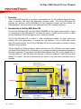
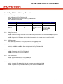
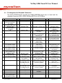
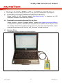
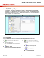
NuTiny-SDK-Nano130 User Manual ARM Cortex™-M0 32-bit Microcontroller NuTiny-SDK-Nano130 User Manual for NuMicro™ Nano130 Series The information described in this document is the exclusive intellectual property of Nuvoton Technology Corporation and shall not be reproduced without permission from Nuvoton. Nuvoton is providing this document only for reference purposes of NuMicro™ microcontroller based system design. Nuvoton assumes no responsibility for errors or omissions. All data and specifications are subject to change without notice. For additional information or questions, please contact: Nuvoton Technology Corporation. Oct. 16, 2012 Revision V1.0 NuTiny-SDK-Nano130 User Manual Table of Contents 1 Overview .................................................................................................... 3 2 Introduction to NuTiny-SDK-Nano130 ................................................................. 3 2.1 2.2 2.3 3 NuTiny-SDK-Nano130 Jumper Description ................................................................. 4 Pin Assignment for Extended Connectors .................................................................. 5 NuTiny-SDK-Nano130 PCB Placement ..................................................................... 7 Starting to Use NuTiny -SDK-Nano130 on the Keil μVision® IDE ................................. 8 3.1 3.2 3.3 3.4 4 Downloading and Installing Keil μVision ® IDE Software ................................................... 8 Downloading and Installing Nuvoton Nu-Link Driver ....................................................... 8 Hardware Setup ................................................................................................. 8 LCD_DEMO Example Program ............................................................................... 9 Starting to Use NuTiny-SDK-Nano130 on the IAR Embedded Workbench.................... 10 4.1 4.2 4.3 4.4 Downloading and Installing IAR Embedded Workbench Software .................................... 10 Downloading and Installing Nuvoton Nu-Link Driver ..................................................... 10 Hardware Setup ............................................................................................... 10 LCD_DEMO Example Program ............................................................................. 11 5 NuTiny-EVB-Nano130 Schematics ................................................................... 12 6 Downloading NuMicro Related Files from Nuvoton Website ................................... 14 ™ 6.1 6.2 6.3 7 Downloading NuMicro™ Keil μVision® IDE Driver......................................................... 14 Downloading NuMicro™ IAR EWARM Driver .............................................................. 16 Downloading NuMicro™ Nano100 series BSP Software Library ....................................... 18 Revision History ......................................................................................... 19 Oct. 16, 2012 2 Revision V1.0 NuTiny-SDK-Nano130 User Manual 1 Overview The NuTiny-SDK-Nano130 is a specific development tool for the NuMicro Nano130 series users to develop and verify the application program easily. The NuTiny-SDK-Nano130 includes two portions: NuTiny-EVB-Nano130 (an evaluation board) and Nu-Link-Me (its Debug Adaptor), such that users do not need additional ICE or debug equipment. 2 Introduction to NuTiny-SDK-Nano130 The NuTiny-SDK-Nano130 uses the NANO130KE3BN as the target microcontroller. Figure 2-1 shows the NuTiny-SDK-Nano130 for Nano130 series, in which the left portion is called NuTiny-EVB-Nano130 and the right portion is called Nu-Link-Me. The NuTiny-EVB-Nano130 is similar to other development boards, by which users can develop and verify applications to emulate the real behavior. The on board chip covers Nano130 series features. The NuTiny-EVB-Nano130 can be a real system controller to design the users’ target systems. The Nu-Link-Me is a Debug Adaptor, which connects your PC's USB port to a target system (via Serial Wired Debug Port) and allows you to program and debug embedded programs on the target hardware. To use the Nu-Link-Me Debug adaptor with IAR or Keil, please refer to “Nuvoton NuMicro™ IAR ICE Driver User Manual” or “Nuvoton NuMicro™ Keil ICE Driver User Manual” for details. The two documents will be stored in the local hard disk when each is installed. LQFP-128 pin Extended Connector VDD33 JP15 ICE Controller JP11 LCD Panel J2 J1 GND JP17 Target Chip USB Connector JP16 LQFP-128 pin Extended Connector Reset Key PC12 Key ICE Controller USB Connector Figure 2-1 NuTiny-SDK-Nano130 (Yellow PCB Board) Oct. 16, 2012 3 Revision V1.0 NuTiny-SDK-Nano130 User Manual 2.1 2.1.1 NuTiny-SDK-Nano130 Jumper Description Power Settings J1: USB port in NuTiny-EVB-Nano130 JP2: VDD33 Voltage connector in NuTiny-EVB-Nano130 J2: USB port in Nu-Link-Me Power Model Model 1 J2 USB Port Connect to PC J1 USB Port X JP2 VDD33 DC 3.3V output MCU Voltage DC 3.3V Model 2 X Connect to PC DC3.3V output DC 3.3V Model 3 X X DC 1.8 V ~ 3.6 V Input DC 1.8 V ~ 3.6 V Decided by JP2 VDD33 Input X: Unused. 2.1.2 Debug Connectors JP4: Connector in target board (NuTiny-EVB-Nano130) for connecting with Nuvoton ICE adaptor (Nu-LinkMe) JP8: Connector in ICE adaptor (Nu-Link-Me) for connecting with a target board (e.g. NuTiny-EVBNano130) 2.1.3 USB Connectors J1: Mini USB Connector in NuTiny-EVB-Nano130 for application use J2: Mini USB Connector in Nu-Link-Me connected to a PC USB port 2.1.4 Extended Connectors JP11, JP15, JP16 and JP17: Show all chip pins in NuTiny-EVB-Nano130 2.1.5 Buttons SW1: Reset button in NuTiny-EVB-Nano130 SW2: PC12 button in NuTiny-EVB-Nano130 2.1.6 Power Connectors JP2: VDD33 connector in NuTiny-EVB-Nano130 JP3: GND connector in NuTiny-EVB-Nano130 2.1.7 Power Jumpers JP1: Jumper in ICE adaptor (Nu-Link-Me) for power source selection of JP8. JP9: Jumper in NuTiny-EVB-Nano130 to set power source from JP4 and J1 Oct. 16, 2012 4 Revision V1.0 NuTiny-SDK-Nano130 User Manual 2.2 No 01 02 Pin Assignment for Extended Connectors The NuTiny-EVB-Nano130 provides the NANO130KE3BN target chip on board and the extended connectors (JP11, JP15, JP16 and JP17) for LQFP128-pin. No 33 34 Pin Name PE12/UART1_CTSn PE11/UART1_RTSn No 65 66 Pin Name PE4/SPI0_MOSI0 PE3/SPI0_MISO0 No 97 98 Pin Name VREF NC 35 PE10/UART1_TXD 67 PE2/SPI0_CLK 99 AVDD 36 PE9/UART1_RXD 68 PE1/PWM1_CH3/SPI0_SS0 100 05 Pin Name PE13/ LCD_SEG27 PB14/INT0/SC2_CD/ SPI2_SS1/LCD_SEG12/ LCD_SEG26 PB13/EBI_AD1/ LCD_SEG11/LCD_SEG25 PB12/EBI_AD0/ CLKO/LCD_SEG10/ LCD_SEG24 NC 37 PE8/LCD_SEG9 69 PE0/PWM1_CH2/ I2S_MCLK 101 06 X320 38 PE7/LCD_SEG8 70 102 07 X32I 39 NC 71 08 NC 40 NC 72 09 41 NC 73 42 NC 74 43 NC 75 44 76 14 PD9/LCD_SEG18 46 15 PD10/LCD_SEG17 47 79 PA12/PWM0_CH0/ EBI_AD13/TC0/I2C0_SDA/ CTK10/LCD_SEG24 111 PB15/INT1/ SNOOPER/ LCD_SEG14/LCD_SEG31 16 17 PD11/LCD_SEG16 PD12/LCD_SEG15 48 49 PB0/UART0_RXD/ SPI1_MOSI0/ LCD_SEG1/LCD_SEG7 PB1/UART0_TXD/ SPI1_MISO0/ LCD_SEG0/LCD_SEG6 PB2/UART0_RTSn/ EBI_nWRL/SPI1_CLK/ LCD_COM3/LCD_SEG 5 PB3/UART0_CTSn/ EBI_nWRH/SPI1_SS0/ LCD_COM2/LCD_SEG 4 PD6/LCD_SEG3 PD7/LCD_SEG2 PC8/SPI1_SS0/ EBI_MCLK/I2C1_SDA/ CTK12/LCD_SEG28 PA15/PWM0_CH3/ I2S_MCLK/TC3/SC0_PWR/ UART0_TXD/LCD_SEG27 PA14/PWM0_CH2/ EBI_AD15/TC2/ UART0_RXD/LCD_SEG26 PA13/PWM0_CH1/ EBI_AD14/TC1/I2C0_SCL/ CTK11/LCD_SEG25 107 13 PA11/I2C1_SCL/EBI_nRD/ SC0_RST/SPI2_MOSI0/ LCD_SEG9/LCD_SEG23 PA10/I2C1_SDA/EBI_nWR/ SC0_PWR/SPI2_MISO0/ LCD_SEG8/LCD_SEG22 PA9/I2C0_SCL/ SC0_DAT/SPI2_CLK/ LCD_SEG7/LCD_SEG21 PA8/I2C0_SDA/ SC0_CLK/SPI2_SS0/ LCD_SEG6/LCD_SEG20 PD8/LCD_SEG19 PC13/SPI_MOSI1/ PWM1_CH1/SNOOPER/ INT0/I2C0_SCL PC12/SPI1_MISO1/ PWM1_CH0/ INT0/I2C0_SDA PC11/SPI1_MOSI0/ UART1_TXD/ CTK15/LCD_SEG31 PC10/SPI1_MISO0/ UART1_RXD/ CTK14/LCD_SEG30 PC9/SPI1_CLK/I2C1_SCL/ CTK13/LCD_SEG29 PD0/UART1_RXD/ SPI2_SS0/SC1_CLK/ CTK0/AD8 PD1/UART1_TXD/ SPI2_CLK/SC1_DAT/ AD9/CTK1 PD2/UART1_RTSn/ I2S_LRCLK/SPI2_MISO0/ SC1_PWR/AD10/CTK2 PD3/UART1_CTSn/ I2S_BCLK/SPI2_MOSI0/ SC1_RST/AD11/CTK3 NC 80 81 112 113 NC XT1_IN 18 19 PD13/LCD_SEG14 PB4/UART1_RXD/ SC0_CD/SPI2_SS0/ LCD_SEG5/LCD_SEG13 PB5/UART1_TXD/ 50 51 PD14/LCD_SEG1 PD15/LCD_SEG0 82 83 PF0/ICE_DAT/INT0 PF1/ICE_CLK/ CLKO/INT1 NC VDD 114 115 XT1_OUT NC 52 PC5/SPI0_MOSI1/ 84 NC 116 nRESET 03 04 10 11 12 20 Oct. 16, 2012 45 77 78 5 103 104 105 106 108 109 110 PD4/I2S_DI/ SPI2_MISO1/SC1_CD/ CTK4/LCD_SEG35 PD5/I2S_DO/ SPI2_MOSI1/CTK5/ LCD_SEG34 PC7/DA1_OUT/ EBI_AD5/TC1/ PWM0_CH1/LCD_SEG17 PC6/DA0_OUT/ EBI_AD4/TC0/ SC1_CD/PWM0_CH0 PC15/EBI_AD3/ TC0/PWM1_CH2/ LCD_SEG16/LCD_SEG33 PC14/EBI_AD2/ PWM1_CH3/ LCD_SEG15/LCD_SEG32 Revision V1.0 NuTiny-SDK-Nano130 User Manual 23 SC0_RST/SPI2_CLK/ LCD_SEG4/LCD_SEG12 PB6/UART1_RTSn/ EBI_ALE/SPI2_MISO0/ LCD_SEG3/LCD_SEG11 PB7/UART1_CTSn/ EBI_nCS/SPI2_MOSI0/ LCD_SEG2/LCD_SEG10 NC 24 LDO_CAP 56 25 NC 57 26 27 NC VDD 58 59 PC3/SPI0_MOSI0/ I2S_DO/SC1_RST/ LCD_COM1 PC2/SPI0_MISO0/ I2S_DI/SC1_PWR/ LCD_COM0 PC1/SPI0_CLK/ I2S_BCLK_SC1_DAT/ LCD_DH2 PC0/SPI0_SS0/ I2S_LRCLK/ SC1_CLK/LCD_DH1 PE6 LCD_VLCD 28 NC 60 LCD_VLCD 92 29 VSS 61 PE5 93 30 VSS 62 94 31 VSS 63 32 VSS 64 PB11/PWM1_CH0/ TM3/SC2_DAT/ SPI0_MISO0/LCD_V1 PB10/SPI0_SS1/ TM2/SC2_CLK/ SPI0_MOSI0/LCD_V2 PB9/SPI1_SS1/ TM1/SC2_RST/ INT0/LCD_V3 21 22 LCD_COM3 53 PC4/SPI0_MISO1/ LCD_COM2 85 VSS 117 VSS 54 86 VSS 118 VSS 87 AVSS 119 NC 88 AVSS 120 VDD 89 PA0/AD0/ SC2_CD/CTK8 121 NC 90 91 PA1/AD1/EBI_AD12/CTK9 PA2/AD2/EBI_AD11/ UART1_RXD/LCD_SEG23 PA3/AD3/EBI_AD10/ UART1_TXD/LCD_SEG22 PA4/AD4/EBI_AD9/ SC2_PWR/I2C0_SDA/ LCD_SEG21/LCD_SEG39 PA5/AD5/EBI_AD8/ SC2_RST_I2C0_SCL/ LCD_SEG20/LCD_SEG38 PA6/AD6/EBI_AD7/ TC3/SC2_CLK/PWM0_CH3/ LCD_SEG19/LCD_SEG37 PA7/AD7/EBI_AD6/ TC2/SC2_DAT/ PWM0_CH2/CTK_CAP/ LCD_SEG18/LCD_SEG36 122 123 PF4/I2C0_SDA/CTK6 PF5/I2C0_SCL/CTK7 124 VSS 125 PVSS 126 127 PB8/STADC/TM0/ INT0/SC2_PWR/ LCD_SEG13/LCD_SEG30 PE15/LCD_SEG29 128 PE14/LCD_SEG28 55 95 96 Table 2-1 NANO130KE3BN LQFP 128-pin Assignment for Extended Connectors Oct. 16, 2012 6 Revision V1.0 NuTiny-SDK-Nano130 User Manual 2.3 NuTiny-SDK-Nano130 PCB Placement The following figure shows the NuTiny-SDK-Nano130 PCB placement. Figure 2-2 NuTiny-SDK-Nano130 PCB Placement Oct. 16, 2012 7 Revision V1.0 NuTiny-SDK-Nano130 User Manual 3 Starting to Use NuTiny -SDK-Nano130 on the Keil μVision® IDE 3.1 Downloading and Installing Keil μVision® IDE Software Please connect to the Keil company website (http://www.keil.com) to download the Keil μVision® IDE and install the RVMDK. 3.2 Downloading and Installing Nuvoton Nu-Link Driver Please connect to Nuvoton NuMicro™ website (http://www.nuvoton.com/NuMicro) to download the “NuMicro™ Keil μVision® IDE driver” file. Please refer to section 6.1 for the detailed download flow. After the Nu-Link driver is downloaded, please unzip the file and execute the “Nu-Link_Keil_Driver.exe” to install the driver. 3.3 Hardware Setup The hardware setup is shown in the following figure. Figure 3-1 NuTiny-SDK-Nano130 Hardware Setup Oct. 16, 2012 8 Revision V1.0 NuTiny-SDK-Nano130 User Manual 3.4 LCD_DEMO Example Program This example, as shown in the directory of Figure 3-2, demonstrates the download and debugging of an application on a NuTiny-SDK-Nano130 board. The example file can be downloaded from Nuvoton NuMicro™ website as described in 6.3 Downloading NuMicro™ Nano100 series BSP Software Library. Directory Project File Figure 3-2 LCD_DEMO Example Directory To use this example: The LCD panel on the NuTiny-EVB-Nano130 board will display a NUVOTON logo. Start μVision® Project-Open Open the LCD_DEMO.uvproj project file Project - Build Compile and link the LCD_DEMO application Flash – Download Program the application code into on-chip Flash ROM Oct. 16, 2012 9 Start Debug mode When using the debugger commands, you may: Review variables in the watch window Single step through code Reset the device Run the application Revision V1.0 NuTiny-SDK-Nano130 User Manual 4 Starting to Use NuTiny-SDK-Nano130 on the IAR Embedded Workbench 4.1 Downloading and Installing IAR Embedded Workbench Software Please connect to IAR company website (http://www.iar.com) to download the IAR Embedded Workbench and install the EWARM. 4.2 Downloading and Installing Nuvoton Nu-Link Driver Please connect to Nuvoton Company NuMicro ™ website (http://www.nuvoton.com/NuMicro) to download the “NuMicro™ IAR ICE Driver User Manual” file. Please refer to section 6.2 for the detailed download flow. When the Nu-Link driver has been well downloaded, please unzip the file and execute the “Nu-Link_IAR_Driver.exe” to install the driver. 4.3 Hardware Setup The hardware setup is shown in the following figure. Figure 4-1 NuTiny- SDK-Nano130 Hardware Setup Oct. 16, 2012 10 Revision V1.0 NuTiny-SDK-Nano130 User Manual 4.4 LCD_DEMO Example Program The example, as shown in the directory of Figure 4-2, demonstrates the download and debugging of an application on a NuTiny-SDK-Nano130 board. The example file can be downloaded from Nuvoton NuMicro™ website as described in 6.3 Downloading NuMicro™ Nano100 series BSP Software Library. Directory Project File Figure 4-2 LCD_DEMO Example Directory To use this example: The LCD panel on the NuTiny-EVB-Nano130 board will display a NUVOTON logo. Start IAR Embedded Workbench File-Open-Workspace Open the LCD_DEMO.eww workspace file Project - Make Compile and link the LCD_DEMO application Oct. 16, 2012 11 Project – Download and Debug Program the application code into on-chip Flash ROM Single step through code Reset the device Run the application Revision V1.0 NuTiny-SDK-Nano130 User Manual 5 NuTiny-EVB-Nano130 Schematics VDD33 PIN[1..128] R1 10K 0603R C1 10uF/10V TANT-A DVDD VCC33(B) D1 1 From ICE Bridge's USB Power VDD33 DVDD JP9 1 2 HEADER 2PX1 2 U1 1 3 5 7 9 VCC33(A) TICE_DAT TICE_CLK TICE_RST 2 4 6 8 10 C4 10uF/10V TANT-A HEADER 5PX2 HEADER 5PX2 X32KO X32KI ICE Interface C2 C3 DVDD R2 XTAL2 20pF 0603C X2 12MHz XTAL3-1 33 R4 0603R 1M/DNE 0603R 10uF/10V TANT-A C5 XTAL1 PIN1 PIN2 PIN3 PIN4 PIN5 PIN6 PIN7 PIN8 PIN9 PIN10 PIN11 PIN12 PIN13 PIN14 PIN15 PIN16 PIN17 PIN18 PIN19 PIN20 PIN21 PIN22 PIN23 PIN24 PIN25 PIN26 PIN27 PIN28 PIN29 PIN30 PIN31 PIN32 1 2 3 4 5 6 7 8 9 10 11 12 13 14 15 16 17 18 19 20 21 22 23 24 25 26 27 28 29 30 31 32 SW PUSH BUTTON C13 0.1uF C0603 C14 1uF C0603 CB2 0.1uF C0603 NANO130_LQFP128 PIN33 PIN34 PIN35 PIN36 PIN37 PIN38 PIN39 PIN40 PIN41 PIN42 PIN43 PIN44 PIN45 PIN46 PIN47 PIN48 PIN49 PIN50 PIN51 PIN52 PIN53 PIN54 PIN55 PIN56 PIN57 PIN58 PIN59 PIN60 PIN61 PIN62 PIN63 PIN64 X32KO PA.7 PA.6 PA.5 PA.4 PA.3 PA.2 PA.1 PA.0 AVSS AVSS VSS VSS NC VDD NC ICE_CK/PF.1 ICE_DAT/PF.0 PA.12 PA.13 PA.14 PA.15 PC.8 PC.9 PC.10 PC.11 PC.12 PC.13 PE.0 PE.1 PE.2 PE.3 PE.4 96 95 94 93 92 91 90 89 88 87 86 85 84 83 82 81 80 79 78 77 76 75 74 73 72 71 70 69 68 67 66 65 PIN96 PIN95 PIN94 PIN93 PIN92 PIN91 PIN90 PIN89 PIN88 PIN87 PIN86 PIN85 PIN84 PIN83 PIN82 PIN81 PIN80 PIN79 PIN78 PIN77 PIN76 PIN75 PIN74 PIN73 PIN72 PIN71 PIN70 PIN69 PIN68 PIN67 PIN66 PIN65 DVDD TICE_CLK TICE_DAT DVDD CB5 0.1uF C0603 33 34 35 36 37 38 39 40 41 42 43 44 45 46 47 48 49 50 51 52 53 54 55 56 57 58 59 60 61 62 63 64 DVDD C7 PE.13 PB.14 PB.13 PB.12 NC X32O X32I NC PA.11 PA.10 PA.9 PA.8 PD.8 PD.9 PD.10 PD.11 PD.12 PD.13 PB.4 PB.5 PB.6 PB.7 NC LDO NC NC VDD NC VSS VSS VSS VSS PE.12 PE.11 PE.10 PE.9 PE.8 PE.7 NC VBUS VDD33 USB_DM USB_DP PB.0 PB.1 PB.2 PB.3 PD.6 PD.7 PD.14 PD.15 PC.5 PC.4 PC.3 PC.2 PC.1 PC.0 PE.6 VLCD NC PE.5 PB.11 PB.10 PB.9 20pF 0603C 10pF 0603C nINT0 SW2 PE.14 PE.15 PB.8 PVSS VSS PF.5 PF.4 NC VDD NC VSS VSS RESET NC XT1_Out XT1_In NC PB.15 PC.14 PC.15 PC.6 PC.7 PD.5 PD.4 NC PD.3 PD.2 PD.1 PD.0 AVDD NC VREF SS24A RB060L VCC33(A) JP4 CB4 0.1uF C0603 PIN128 PIN127 PIN126 PIN125 PIN124 PIN123 PIN122 PIN121 PIN120 PIN119 PIN118 PIN117 PIN116 PIN115 PIN114 PIN113 PIN112 PIN111 PIN110 PIN109 PIN108 PIN107 PIN106 PIN105 PIN104 PIN103 PIN102 PIN101 PIN100 PIN99 PIN98 PIN97 VDD33 C15 1uF C0603 128 127 126 125 124 123 122 121 120 119 118 117 116 115 114 113 112 111 110 109 108 107 106 105 104 103 102 101 100 99 98 97 Reset Circuit PIN1 PIN2 PIN3 PIN4 PIN5 PIN6 PIN7 PIN8 PIN9 PIN10 PIN11 PIN12 PIN13 PIN14 PIN15 PIN16 PIN17 PIN18 PIN19 PIN20 PIN21 PIN22 PIN23 PIN24 PIN25 PIN26 PIN27 PIN28 PIN29 PIN30 PIN31 PIN32 PIN33 PIN34 PIN35 PIN36 PIN37 PIN38 PIN39 PIN40 PIN41 PIN42 PIN43 PIN44 PIN45 PIN46 PIN47 PIN48 PIN49 PIN50 PIN51 PIN52 PIN53 PIN54 PIN55 PIN56 PIN57 PIN58 PIN59 PIN60 PIN61 PIN62 PIN63 PIN64 DVDD PIN71 CB3 0.1uF C0603 XTAL2 XTAL1 SW PUSH BUTTON TICE_DAT TICE_CLK TICE_RST TICE_DAT TICE_CLK TICE_RST TICE_RST TICE_RST SW1 X1 32.768KHz XTAL3-1 PIN24 TICE_RST PIN65 PIN66 PIN67 PIN68 PIN69 PIN70 PIN71 PIN72 PIN73 PIN74 PIN75 PIN76 PIN77 PIN78 PIN79 PIN80 PIN81 PIN82 PIN83 PIN84 PIN85 PIN86 PIN87 PIN88 PIN89 PIN90 PIN91 PIN92 PIN93 PIN94 PIN95 PIN96 PIN97 PIN98 PIN99 PIN100 PIN101 PIN102 PIN103 PIN104 PIN105 PIN106 PIN107 PIN108 PIN109 PIN110 PIN111 PIN112 PIN113 PIN114 PIN115 PIN116 PIN117 PIN118 PIN119 PIN120 PIN121 PIN122 PIN123 PIN124 PIN125 PIN126 PIN127 PIN128 DVDD C8 VDD33 C9 0.1uF C0603 C10 1uF C0603 1 C12 1uF C0603 VDD33 1 10pF 0603C 1 X32KI TP1 SIP/1P TP2 SIP/1P TP3 SIP/1P JP2 R11 330 0603R Crystal 1 2 2 1 HEADER 2PX1 HEADER 2PX1 PIN58 IO KPT-2012 KP-2012 JP3 1 2 HEADER 2PX1 HEADER 2PX1 Title NuTiny-EVB-Nano130-LQFP128 V1.1 Size Document Number Custom Date: Oct. 16, 2012 12 Rev V1.1 NANO130KE3BN.SCH Wednesday , October 31, 2012 Sheet 2 of 3 Revision V1.0 NuTiny-SDK-Nano130 User Manual PIN127 PIN125 PIN123 PIN121 PIN119 PIN117 PIN115 PIN113 PIN111 PIN109 PIN107 PIN105 PIN103 PIN101 PIN99 PIN97 PIN[1..128] 31 29 27 25 23 21 19 17 15 13 11 9 7 5 3 1 PIN1 PIN2 PIN3 PIN4 PIN5 PIN6 PIN7 PIN8 PIN9 PIN10 PIN11 PIN12 PIN13 PIN14 PIN15 PIN16 PIN17 PIN18 PIN19 PIN20 PIN21 PIN22 PIN23 PIN24 PIN25 PIN26 PIN27 PIN28 PIN29 PIN30 PIN31 PIN32 U4 RT9164A-3.3V JP11 R12 33 0603R USB_DM USB_DP R13 33 0603R 1 2 3 4 5 J1 VCC DM DP NC GND 32 30 28 26 24 22 20 18 16 14 12 10 8 6 4 2 OUT PIN128 PIN126 PIN124 PIN122 PIN120 PIN118 PIN116 PIN114 PIN112 PIN110 PIN108 PIN106 PIN104 PIN102 PIN100 PIN98 CT4 10uF/10V TANT-A 6 7 8 9 SHIELD SHIELD SHIELD SHIELD PIN127 PIN125 PIN123 PIN121 PIN119 PIN117 PIN115 PIN113 PIN111 PIN109 PIN107 PIN105 PIN103 PIN101 PIN99 PIN97 PIN42 PIN43 VBUS mini USB 5pin USB_MINI_B L1 L0603 31 29 27 25 23 21 19 17 15 13 11 9 7 5 3 1 PIN40 4 3 1 2 IN GND OUT HEADER 16PX2 VCC33(B) JP1 PIN65 PIN66 PIN67 PIN68 PIN69 PIN70 PIN71 PIN72 PIN73 PIN74 PIN75 PIN76 PIN77 PIN78 PIN79 PIN80 PIN81 PIN82 PIN83 PIN84 PIN85 PIN86 PIN87 PIN88 PIN89 PIN90 PIN91 PIN92 PIN93 PIN94 PIN95 PIN96 PIN97 PIN98 PIN99 PIN100 PIN101 PIN102 PIN103 PIN104 PIN105 PIN106 PIN107 PIN108 PIN109 PIN110 PIN111 PIN112 PIN113 PIN114 PIN115 PIN116 PIN117 PIN118 PIN119 PIN120 PIN121 PIN122 PIN123 PIN124 PIN125 PIN126 PIN127 PIN128 PIN128 PIN126 PIN124 PIN122 PIN120 PIN118 PIN116 PIN114 PIN112 PIN110 PIN108 PIN106 PIN104 PIN102 PIN100 PIN98 32 30 28 26 24 22 20 18 16 14 12 10 8 6 4 2 HEADER 16PX2, 2.00mm PIN33 PIN34 PIN35 PIN36 PIN37 PIN38 PIN39 PIN40 PIN41 PIN42 PIN43 PIN44 PIN45 PIN46 PIN47 PIN48 PIN49 PIN50 PIN51 PIN52 PIN53 PIN54 PIN55 PIN56 PIN57 PIN58 PIN59 PIN60 PIN61 PIN62 PIN63 PIN64 JP15 PIN1 PIN3 PIN5 PIN7 PIN9 PIN11 PIN13 PIN15 PIN17 PIN19 PIN21 PIN23 PIN25 PIN27 PIN29 PIN31 1 3 5 7 9 11 13 15 17 19 21 23 25 27 29 31 JP5 2 4 6 8 10 12 14 16 18 20 22 24 26 28 30 32 PIN2 PIN4 PIN6 PIN8 PIN10 PIN12 PIN14 PIN16 PIN18 PIN20 PIN22 PIN24 PIN26 PIN28 PIN30 PIN32 PIN1 PIN3 PIN5 PIN7 PIN9 PIN11 PIN13 PIN15 PIN17 PIN19 PIN21 PIN23 PIN25 PIN27 PIN29 PIN31 1 3 5 7 9 11 13 15 17 19 21 23 25 27 29 31 JP6 2 4 6 8 10 12 14 16 18 20 22 24 26 28 30 32 PIN2 PIN4 PIN6 PIN8 PIN10 PIN12 PIN14 PIN16 PIN18 PIN20 PIN22 PIN24 PIN26 PIN28 PIN30 PIN32 PIN96 PIN94 PIN92 PIN90 PIN88 PIN86 PIN84 PIN82 PIN80 PIN78 PIN76 PIN74 PIN72 PIN70 PIN68 PIN66 32 30 28 26 24 22 20 18 16 14 12 10 8 6 4 2 JP16 31 29 27 25 23 21 19 17 15 13 11 9 7 5 3 1 PIN95 PIN93 PIN91 PIN89 PIN87 PIN85 PIN83 PIN81 PIN79 PIN77 PIN75 PIN73 PIN71 PIN69 PIN67 PIN65 PIN96 PIN94 PIN92 PIN90 PIN88 PIN86 PIN84 PIN82 PIN80 PIN78 PIN76 PIN74 PIN72 PIN70 PIN68 PIN66 32 30 28 26 24 22 20 18 16 14 12 10 8 6 4 2 31 29 27 25 23 21 19 17 15 13 11 9 7 5 3 1 PIN95 PIN93 PIN91 PIN89 PIN87 PIN85 PIN83 PIN81 PIN79 PIN77 PIN75 PIN73 PIN71 PIN69 PIN67 PIN65 VDD33 HEADER 16PX2, 2.00mm R14 100K HEADER 16PX2 ADC0 2 4 6 8 10 12 14 16 18 20 22 24 26 28 30 32 PIN89 HEADER 16PX2, 2.00mm PIN34 PIN36 PIN38 PIN40 PIN42 PIN44 PIN46 PIN48 PIN50 PIN52 PIN54 PIN56 PIN58 PIN60 PIN62 PIN64 HEADER 16PX2 Thermistor JP7 NTC1 C11 100K 0.1uF 1 3 5 7 9 11 13 15 17 19 21 23 25 27 29 31 HEADER 16PX2, 2.00mm PIN33 PIN35 PIN37 PIN39 PIN41 PIN43 PIN45 PIN47 PIN49 PIN51 PIN53 PIN55 PIN57 PIN59 PIN61 PIN63 PIN90 CTKey _SLIDER PIN75 PIN78 5 JP17 CTK14 HEADER 16PX2 CTK13 1 3 5 7 9 11 13 15 17 19 21 23 25 27 29 31 PIN74 CTK15 CTK12 CTK11 PIN33 PIN35 PIN37 PIN39 PIN41 PIN43 PIN45 PIN47 PIN49 PIN51 PIN53 PIN55 PIN57 PIN59 PIN61 PIN63 PIN73 2 2 4 6 8 10 12 14 16 18 20 22 24 26 28 30 32 1 PIN72 4 3 PIN34 PIN36 PIN38 PIN40 PIN42 PIN44 PIN46 PIN48 PIN50 PIN52 PIN54 PIN56 PIN58 PIN60 PIN62 PIN64 K1 Title NuTiny-EVB-Nano130-LQFP128 V1.1 Size Document Number Custom Date: Oct. 16, 2012 13 Rev V1.1 OTHER.SCH Wednesday , October 31, 2012 Sheet 3 of 3 Revision V1.0 NuTiny-SDK-Nano130 User Manual 6 6.1 Downloading NuMicro™ Related Files from Nuvoton Website Downloading NuMicro™ Keil μVision® IDE Driver ™ Step 1 Visit the Nuvoton NuMicro website: http://www.nuvoton.com/NuMicro Step 2 Click here to enter Device Driver and Software Library. Oct. 16, 2012 14 Revision V1.0 NuTiny-SDK-Nano130 User Manual Step 3 Step 4 Download the NuMicro Keil μVision® IDE driver. Oct. 16, 2012 15 Revision V1.0 NuTiny-SDK-Nano130 User Manual 6.2 Downloading NuMicro™ IAR EWARM Driver Step 1 Visit the Nuvoton NuMicro™ website: http://www.nuvoton.com/NuMicro Step 2 Click here to enter Device Driver and Software Library. Oct. 16, 2012 16 Revision V1.0 NuTiny-SDK-Nano130 User Manual Step 3 Step 4 Download the NuMicro™ IAR Embedded Workbench® driver. Oct. 16, 2012 17 Revision V1.0 NuTiny-SDK-Nano130 User Manual 6.3 Downloading NuMicro™ Nano100 series BSP Software Library Step 1 Visit the Nuvoton NuMicro™ website: http://www.nuvoton.com/NuMicro Step 2 Click here to enter Device Driver and Software Library. Step 3 Download the NuMicro™ Nano100 series software library. Oct. 16, 2012 18 Revision V1.0 NuTiny-SDK-Nano130 User Manual 7 Revision History Revision Date 1.0 Oct. 16, 2012 Description Preliminary version Important Notice Nuvoton products are not designed, intended, authorized or warranted for use as components in systems or equipment intended for surgical implantation, atomic energy control instruments, airplane or spaceship instruments, transportation instruments, traffic signal instruments, combustion control instruments, or for other applications intended to support or sustain life. Further more, Nuvoton products are not intended for applications wherein failure of Nuvoton products could result or lead to a situation wherein personal injury, death or severe property or environmental damage could occur. Nuvoton customers using or selling these products for use in such applications do so at their own risk and agree to fully indemnify Nuvoton for any damages resulting from such improper use or sales. Please note that all data and specifications are subject to change without notice. All the trademarks of products and companies mentioned in this datasheet belong to their respective owners. Oct. 16, 2012 19 Revision V1.0