1
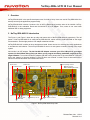
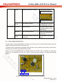
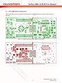
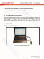
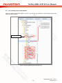
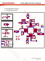
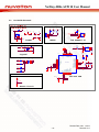
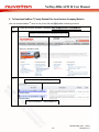
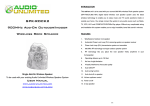
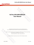
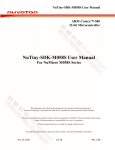
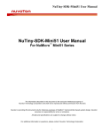
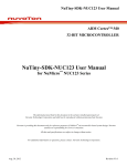
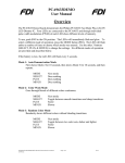
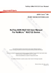
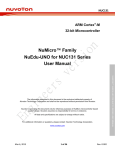
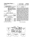
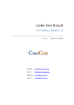
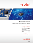
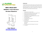
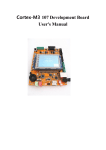
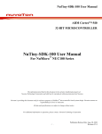
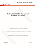
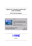
NuTiny-SDK-AU9110 User Manual ARM Cortex™-M0 32-BIT MICROCONTROLLER NuTiny-SDK-AU9110 User Manual ™ For NuMicro AU9110 The information described in this document is the exclusive intellectual property of Nuvoton Technology Corporation and shall not be reproduced without permission from Nuvoton. Nuvoton is providing this document only for reference purposes of NuMicro TM microcontroller based system design. Nuvoton assumes no responsibility for errors or omissions. All data and specifications are subject to change without notice. For additional information or questions, please contact: Nuvoton Technology Corporation. -1- Publication Release Date: Nov.1, 2013 Revision V1.0 NuTiny-SDK-AU9110 User Manual 1 Overview ................................................................................................................... 3 2 NuTiny-SDK-AU9110 Introduction ............................................................................ 3 2.1 NuTiny-SDK-AU9110 Jumper Description ............................................................... 5 2.2 Power setting of AU9110 chip .................................................................................. 6 2.3 NuTiny-SDK-AU9110 PCB Placement ..................................................................... 7 3 3.1 3.2 3.3 3.4 How to start NuTiny-SDK-AU9110 on the Keil μVision IDE ...................................... 8 Keil μVision IDE Software Download and Install ...................................................... 8 Installing Nuvoton Nu-Link Driver ............................................................................. 8 Hardware Setup ....................................................................................................... 8 Run a sample project on Keil platform ..................................................................... 9 4.1 4.2 4.3 4.4 How to Start NuTiny-SDK-AU9110 on the IAR Embedded Workbench .................. 11 IAR Embedded Workbench Software Download and Install .................................. 11 Nuvoton Nu-Link Driver Download and Install ........................................................ 11 Hardware Setup ..................................................................................................... 11 Run a sample project on IAR platform ................................................................... 12 4 5 NuTiny-SDK-AU9110 Schematic ............................................................................ 13 5.1 NuTiny-EVB-AU9110 Schematic............................................................................ 13 5.2 Nu-Link-Me Schematic ........................................................................................... 14 6 To Download NuMicro™ Family Related Files from Nuvoton Company Website ... 15 7 Revision History ...................................................................................................... 16 -2- Release Date: Nov. 1, 2013 Revision V1.0 NuTiny-SDK-AU9110 User Manual 1 Overview NuTiny-SDK-AU9110 is the specific development tool for AU9110 chip. Users can use NuTiny-SDK-AU9110 to develop and verify the application program easily. NuTiny-SDK-AU9110 includes 2 portions. One is NuTiny-EVB-AU9110 and the other is Nu-Link-Me. NuTinyEVB-AU9110 is the evaluation board and Nu-Link-Me is its ICE adaptor. Thus, users do not need other additional ICE or debug equipment. 2 NuTiny-SDK-AU9110 Introduction The Figure 1 and Figure 2 show the top side and bottom side of NuTiny-SDK-AU9110 respectively. The left portion of NuTiny-SDK-AU9110 is called NuTiny-EVB-AU9110, which uses the AU9110LF3AN as the target microcontroller. And the right portion is ICE adaptor called Nu-Link-Me. NuTiny-EVB-AU9110 is similar to other development board. Users can use it to develop and verify applications to emulate the real behavior. The NuTiny-EVB-AU9110 can be a real system controller to design user target system. Nu-Link-Me is an ICE adaptor. The Nu-Link-Me ICE Adaptor connects your PC's USB port to your target system (via Serial Wired Debug Port) and allows you to program and debug embedded programs on the target hardware. To use Nu-Link-Me ICE adaptor with IAR or Keil, please refer to “Nuvoton NuMicro™ IAR ICE driver user manual “or Nuvoton NuMicro™ Keil ICE driver user manual” in detail. These 2 documents will be stored in local hard disk when user installs each driver. RESET button AU9110 chip WAKEUP button 10 4 AU9110 pin 1~12 7 AU9110 pin 37~48 ICE chip debug interface 11 Power selector. It is soldered to VCC33 NC NC NC NC NC Power LED 3 SPEAKER 1 Power VDD 2 Power GND 5 AU9110 pin 13~24 9 Debug connector 8 ICE adaptor connector 6 AU9110 pin 25~36 Mini USB connector connected to PC USB port Figure 1: NuTiny-SDK-AU9110 top side. -3- Release Date: Nov. 1, 2013 Revision V1.0 NuTiny-SDK-AU9110 User Manual SPI flash chip W25Q16 Connected to PA.0~PA.3 Figure 2: NuTiny-SDK-AU9110 bottom side. -4- Release Date: Nov. 1, 2013 Revision V1.0 NuTiny-SDK-AU9110 User Manual 2.1 NuTiny-SDK-AU9110 Jumper Description Board Component Name Description Remark NuTinyEVB-Au9110 ① JP6 Power VDD input connector Can be DC 2.4V-5.5V ② JP7 Power GND input connector ③ SPEAKER Speaker connector ④ JP1 AU9110 pin extension connector AU9110 pin number 1 1 9 7 5 3 1 1 2 ⑤ JP2 AU9110 pin extension connector AU9110 pin extension connector 6 4 2 1 1 1 2 2 NC NC NC 5 7 9 1 3 AU9110 pin number 1 1 2 2 2 2 6 8 0 2 4 6 2 5 -5- 8 AU9110 pin number 1 1 1 2 2 2 NC NC 4 6 8 0 2 4 1 3 ⑥ JP3 1 0 2 7 2 9 3 1 3 3 3 5 Release Date: Nov. 1, 2013 Revision V1.0 NuTiny-SDK-AU9110 User Manual ⑦ JP4 AU9110 pin extension connector AU9110 pin number 4 4 4 4 3 3 7 5 3 1 9 7 4 8 Nu-Link-Me 2.2 4 6 4 4 4 2 4 0 3 8 ⑧ JP5 ICE adaptor connector For connecting with Nuvoton ICE adaptor (Nu-Link-Me). ⑨ ICEJP8 Debug connector For connecting with a target board (for example, NuTinyEVB-Au9110). ⑩ICEJP9 ICE chip debug interface Only used to fix the firmware of ICE chip. User does not need to care. ⑪JP8 Power selector (VCC5 or VCC3.3) of ICE chip It is soldered to VCC3.3 at factory. Power setting of AU9110 chip The input power of NuTiny-EVB-AU9110 can have two sources. One is from Nu-Link-Me through ⑧JP5 (ICE adaptor connector) and the other is from (JP6, JP7). The AU9110 chip is powered by ICE adaptor which provides 3.3V by soldering JP8 at factory, when NuTinyEVB-Au9110 is connected to ICE adaptor (Nu-Link-Me). However if the NuTiny-EVB-AU9110 is separated alone, the AU9110 chip is powered by (JP6, JP7). DC2.4V~5.5V is applicable from (JP6, JP7). Figure 3 shows the power setting for a separate NuTiny-EVBAU9110. GND DC2.4V~5.5V Figure 3: The power setting for a separate NuTiny-EVB-AU9110.. -6- Release Date: Nov. 1, 2013 Revision V1.0 NuTiny-SDK-AU9110 User Manual 2.3 NuTiny-SDK-AU9110 PCB Placement User can refer to Figure 4 for top placement of the NuTiny-SDK-AU9110 PCB, and Figure 5 for the bottom placement. Figure 4: The top placement of Nutiny-SDK-AU9110 PCB. Figure 5: The bottom placement of Nutiny-SDK-AU9110 PCB. -7- Release Date: Nov. 1, 2013 Revision V1.0 NuTiny-SDK-AU9110 User Manual 3 How to start NuTiny-SDK-AU9110 on the Keil μVision IDE 3.1 Keil μVision IDE Software Download and Install Please visit the Keil company website (http://www.keil.com) to download the MDK-ARM software, which supports the Keil μVision IDE. The µVision IDE from Keil combines project management, make facilities, source code editing, program debugging, and complete simulation in one powerful environment. The example codes for AU9110 are prepared by Nuvoton and called AU9110_BSP. They are well tested on MDK-ARM V4.72a. So the later version after MDK-ARM V4.72a is suggested to develop the project for AU9110. 3.2 Installing Nuvoton Nu-Link Driver Please visit Nuvoton company NuMicro™ website (http://www.nuvoton.com/NuMicro) to download Nu-Link driver for Keil μVision IDE. Please refer to the Chapter 6 for the detail download flow. When the Nu-Link driver have been download ok, please unzip the file and then execute the “Nu-Link_Driver_for_Keil_RVMDK_vx.xx.xxxx.exe” to install the driver, where the vx.xx.xxxx represents the version number of driver. 3.3 Hardware Setup The hardware setup is shown in the following Figure 6. Figure 6: NuTiny-SDK-AU9110 Hardware Setup. -8- Release Date: Nov. 1, 2013 Revision V1.0 NuTiny-SDK-AU9110 User Manual 3.4 Run a sample project on Keil platform The example code for AU9110 is called AU9110_BSP, It is delivered on CD. When you already install AU9110_BSP in your PC, you can find a keil subfolder in every sample project folder which is shown in Figure 7. Sample project folders Figure 7: AU9110_BSP Sample Project Directory. You can use the following procedure to download a sample code to AU9110 chip in the NuTiny-EVB-AU9110. The sample project „Smpl_AudioSynEx‟ is illustrated in the procedure only, user can select other desire sample project. -9- Release Date: Nov. 1, 2013 Revision V1.0 NuTiny-SDK-AU9110 User Manual Actions Remark Start μVision IDE Step 1. Click Step 2. Open the Smpl_AudioSynEx.uvproj project file Step 3. Compile and link the Smpl_AudioSynEx application Step 4. Program the application code into on-chip program flash - 10 - Release Date: Nov. 1, 2013 Revision V1.0 NuTiny-SDK-AU9110 User Manual 4 How to Start NuTiny-SDK-AU9110 on the IAR Embedded Workbench 4.1 IAR Embedded Workbench Software Download and Install Please connect to IAR company website (http://www.iar.com) to download the IAR Embedded Workbench and install the EWARM. 4.2 Nuvoton Nu-Link Driver Download and Install Please connect to Nuvoton company NuMicro™ website (http://www.nuvoton.com/NuMicro) to download NuLink driver for IAR ICE. Please refer to the Chapter 6 for the detail download flow. When the Nu-Link driver have been download ok, please unzip the file and then execute the “NuLink_Driver_for_IAR_EWARM_Vx.xx.xxxx.exe” to install the driver, where the Vx.xx.xxxx represents the version number of driver. 4.3 Hardware Setup The hardware setup is shown in Figure 8. Figure 8: NuTiny-SDK-AU9110 Hardware Setup. - 11 - Release Date: Nov. 1, 2013 Revision V1.0 NuTiny-SDK-AU9110 User Manual 4.4 Run a sample project on IAR platform When you already install AU9110_BSP in your PC, you can find a iar subfolder in every sample project folder which is shown in Figure 9. Sample project folders Figure 9: AU9110_BSP Sample Project Directory. - 12 - Release Date: Nov. 1, 2013 Revision V1.0 NuTiny-SDK-AU9110 User Manual 5 NuTiny-SDK-AU9110 Schematic VCC D R43 10K R0603 11 9 7 5 3 1 P47 P45 P43 P41 P39 P37 NuTiny-EVB-AU9110 Schematic JP4 12 10 8 6 4 2 5.1 HEADER 6PX2 HEADER6X2 TICERST RESETN RESETN C39 10uF/10V P48 P46 P44 P42 P40 P38 3216 0.1UF 1 C43 C10 2 4.7UF 1 C17 47UF 2 VCC F 2 Serial Flash 1 Reset Circuit 25Q_SPI_MOSI0 25Q_SPI_SCLK 25Q_SPI_SSB0 25Q_SPI_MISO0 2 VCC A GPIOA_0 GPIOA_1 GPIOA_2 GPIOA_3 U2 20p C4 PA.10 PA.11 VCCA MICBIAS MICMIC+ VMID VSSA XI32K XO32K PA.12 PA.13 WAKEUP 2 MIC0.1UF C22 47UF C7 1UF R3 2.2K MICRPHONE GPIOA_15 GPIOA_9 GPIOA_8 2 C49 0.1UF 0 C25 Must put C25, C49 close 47UF to pins 17, 19 & 21. L3 RED_LED D1 2 8.2uH R1 1.2K 1 L6 JP2 HEADER 6PX2 HEADER6X2 2 8.2uH SPKSPK+ 2 1 J13 CON2 PWR_ON Battery Power P23 8.2uH 1 SPEAKER 2 1uH VCC SPK 2 1 L5 L1 2 4 6 8 10 12 1 8.2uH HEADER 2PX1 SIP-2P 1 2 2 P13 P15 L2 1 1 JP7 P24 P23 P22 12 11 10 9 8 7 6 5 4 3 2 1 HEADER 6PX2 HEADER6X2 VSSSPK VCC A 1 3 5 7 9 11 VCC D VSSSPK - 13 - TP2 C18 0.1UF Battery Power 2 1 2 C19 1UF P22 P24 2 P14 P16 1 R54 TP1 VCC D VCC SPK 1 L0603 VCC FS JP3 1 VCC D L4 JP6 P36 P35 P34 P33 P32 P31 P30 P29 P28 P27 P26 P25 P36 P34 P32 P30 P28 P26 TICECLK TICEDAT TICERST P13 P14 P15 P16 2 VCC B HEADER 2PX1 SIP-2P GPIOA_14 VCC FS GPIOA_0 GPIOA_1 VCC F GPIOA_2 GPIOA_3 GPIOA_4 GPIOA_5 GPIOA_6 GPIOA_7 2 MICROPHON E 36 35 34 33 32 31 30 29 28 27 26 25 1 C3 VREG AU9110 PA.14 VCC LDO PA.0 PA.1 VDD 33 LQFP48 PA.2 PA.3 PA.4 PA.5 PA.6 PA.7 VSSD NC13 PA.15 PA.9 PA.8 VCCSPK SPK+ VSSSPK SPKVCCSPK RESETN ICE_DAT ICE_CLK 1 C2 C45 0.1UF 1 2 MIC+ 0.1UF WAKEUP PB.7 PB.6 PB.5 PB.4 PB.3 PB.2 PB.1 PB.0 VCC D VREG NC12 13 14 15 16 17 18 19 20 21 22 23 24 1 2 1 1 MK1 P2 P4 P6 P8 P10 P12 1 2 3 4 5 6 7 8 9 10 11 12 2 2 MIC VCC D 1 2 3 4 5 6 7 8 9 10 11 12 HEADER 6PX2 HEADER6X2 2 JP1 P1 P3 P5 P7 P9 P11 C1 4.7UF 1 2 R2 2.2K 2 1 1 MICBIAS WAKEUP GPIOB_7 GPIOB_6 GPIOB_5 GPIOB_4 GPIOB_3 GPIOB_2 GPIOB_1 GPIOB_0 1 U1 0.1uF P1 P2 P3 P4 P5 P6 P7 P8 P9 P10 P11 P12 VCC F C5 20p P38 P37 2 R44 10K GPIOA_12 GPIOA_13 48 47 46 45 44 43 42 41 40 39 38 37 C41 ICE Interface GPIOA_11 GPIOA_10 1 VCC D P47 P48 X1 32.768K XTAL-3.4MM-2P P39 1 W25Q TICEDAT TICECLK TICERST 1 TICEDAT TICECLK TICERST C21 0.1UF 25Q_SPI_SCLK 25Q_SPI_MOSI0 MICBIAS MICMIC+ VMID 1 2 3 4 5 6 7 8 9 10 HEADER 5PX2 HEADER5X2 8 7 6 5 2 JP5 CS VCC DO HOLD WP CLK GND DIO P46 P45 P44 P43 P42 P41 P40 1 2 3 4 25Q_SPI_SSB0 25Q_SPI_MISO0 VCC B 1 From ICE Bridge's USB Power Release Date: Nov. 1, 2013 Revision V1.0 P35 P33 P31 P29 P27 P25 NuTiny-SDK-AU9110 User Manual Nu-Link-Me Schematic 2 VCC 33 1 OUT 1 VCC RTIDA1 100K R0603 VCC RICK1 100K R0603 VCC B iceD2 SS24A RB060L iceJP9 iceL4 3 JP8 3-W JUMPER L0603 VCC 33 4 3 1 2 IN GND OUT U3 RT9164A-3.3V VCC AVDD VCC 5 VCC iceD3 SS24A RB060L 2 SS24A RB060L 2 VCC 1 1 VCC VCC 5 iceD4 USBVBUS 2 iceL5 iceJP8 1 ICE_DAT 2 ICE_CLK 3 ICE_RST 4 5 HEADER 5PX1 SIP-5P 1 2 3 4 5 6 7 8 9 10 HEADER 5PX2 HEADER5X2 TICEDAT TICECLK TICERST TICEDAT TICECLK TICERST L0603 CT3 10uF/10V TANT-A POWER ADAVSS DEBUG ICE CONNECT IF USBVBUS iceC6 VCC USB_DUSB_D+ 20pF/DN E iceX3 C0603 12MHz XTAL\LP\SMD iceC7 ICE_RST 12M_I 12M_O 12M_I Crystal 1 (RED) KPT-2012 KP-2012 ICP ICPLED 2 1 (YELLOW) 2 4 6 8 iceRP1 1 3 5 7 8P4R-330 8P4RA ICELED ICPLED RED GREEN VCC KP-2012 KPT-2012 IDLE 2 RED 1 (RED) KPT-2012 KP-2012 iceCT1 10uF/10V TANT-A iceCB3 0.1uF C0603 1 2 3 4 5 6 7 8 9 10 11 12 13 14 15 16 INT0/PB14 CPO1/PB13 CPO0/PB12 X32I X32O I2C1SCL/PA11 I2C1SDA/PA10 I2C0SCL/PA9 I2C0SDA/PA8 RX1/PB4 TX1/PB5 RTS1/PB6 CTS1/PB7 LDO VDD VSS BUSY 1 GREEN 2 KPT-2012 KP-2012 USBVBUS NUC12SRE3AN iceJ2 VCC SHIELD DM SHIELD DP SHIELD NC SHIELD GND mini USB 5pin USB_MIN I_B 6 7 8 9 VBUS VCC USBVBUS iceC8 1uF C0603 iceR17 10K R0603 USB_D+ USB_D- PA4/ADC4 PA3/ADC3 PA2/ADC2 PA1/ADC1 PA0/ADC0 AVSS ICE_CK ICE_DAT PA12/PWM0 PA13/PWM1 PA14/PWM2 PA15/PWM3 PC8/SS10 PC9/SPCLK1 PC10/SDI10 PC11/SDO10 48 47 46 45 44 43 42 41 40 39 38 37 36 35 34 33 TP6 VCC ICE_CLK ICE_DAT RRSET1 100K R0603 RTCK1 100K R0603 TICERST TICECLK TICEDAT RTDA2 0 R0603 RTDA3 33 R0603 MCU and USB iceCB4 0.1uF C0603 ICE_RST iceC9 10uF/10V TANT-A Reset Circuit - 14 - iceL6 L0603 TP7 17 18 19 20 21 22 23 24 25 26 27 28 29 30 31 32 (GREEN) AVDD STADC/TM0/PB8 PVSS VDD1 VSS1 /RESET XT1_In XT1_Out INT1/PB15 CPP1/PC14 CPN1/PC15 CPP0/PC6 CPN0/PC7 AVDD ADC7/PA7 ADC6/PA6 ADC/PA5 iceU2 VCC ICE ICELED 2 iceR16 33 R0603 64 63 62 61 60 59 58 57 56 55 54 53 52 51 50 49 20pF/DN E C0603 1 2 3 4 5 1 iceR13 1M/DNE R0603 1 33 R0603 iceR14 33 R0603 ADAVSS iceR12 12M_O VBUS VDD33 DD+ PB0/RX0 PB1/TX0 PB2/RTS0 PB3/CTS0 PC3/SDO00 PC2/SDI00 PC1/SPCLK0 PC0/SS00 PE5 PB11/TM3 PB10/SS01/TM2 PB9/SS11/TM1 5.2 Release Date: Nov. 1, 2013 Revision V1.0 RTDA1 100K R0603 NuTiny-SDK-AU9110 User Manual 6 To Download NuMicro™ Family Related Files from Nuvoton Company Website User can download NuMicro Step 1. Step 2. Step 3. TM driver for Keil μVision IDE and IAR EWARM at following procedure. To visit the Nuvoton NuMicro™ Website: http://www.nuvoton.com/NuMicro Click here to enter Device Driver and Software Library page To download NuMicroTM Keil μVision® IDE driver To download NuMicroTM IAR EWARM driver - 15 - Release Date: Nov. 1, 2013 Revision V1.0 NuTiny-SDK-AU9110 User Manual 7 Revision History Version V1.0 Date Nov. 1, 2013 Page - Description First Release. Important Notice Nuvoton products are not designed, intended, authorized or warranted for use as components in systems or equipment intended for surgical implantation, atomic energy control instruments, airplane or spaceship instruments, transportation instruments, traffic signal instruments, combustion control instruments, or for other applications intended to support or sustain life. Furthermore, Nuvoton products are not intended for applications wherein failure of Nuvoton products could result or lead to a situation where personal injury, death or severe property or environmental damage could occur. Nuvoton customers using or selling these products for use in such applications do so at their own risk and agree to fully indemnify Nuvoton for any damages resulting from such improper use or sales. Please note that all data and specifications are subject to change without notice. All the trademarks of products and companies mentioned in this datasheet belong to their respective owners. - 16 - Release Date: Nov. 1, 2013 Revision V1.0