1
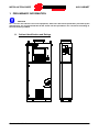
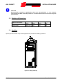
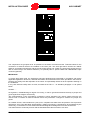
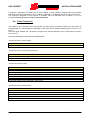
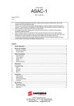
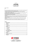
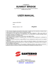
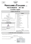
15P00EJB100 AUXILIARY CABINET AUXILIARY SERVICES AND LV DISTRIBUTION CABINET USER MANUAL - INSTALLATION GUIDE - Updated: 24/10/2012 English Rev. 01 • This manual is integrant and essential to the product. Carefully read the instructions contained herein as they provide important hints for use and maintenance safety. • This product is to be used only for the purposes it has been designed to. Other uses should be considered improper and dangerous. The manufacturer is not responsible for possible damages caused by improper, erroneous and irrational uses. • Elettronica Santerno is responsible for the product in its original setting. • Any changes to the structure or operating cycle of the product must be performed or authorized by Elettronica Santerno. • Elettronica Santerno assumes no responsibility for the consequences resulting by the use of nonoriginal spare-parts. • Elettronica Santerno reserves the right to make any technical changes to this manual and to the product without prior notice. If printing errors or similar are detected, the corrections will be included in the new releases of the manual. • The information contained herein is the property of Elettronica Santerno and cannot be reproduced. Elettronica Santerno enforces its rights on the drawings and catalogues according to the law. Elettronica Santerno S.p.A. Strada Statale Selice, 47 - 40026 Imola (BO) Italy Tel. +39 0542 489711 - Fax +39 0542 489722 santerno.com [email protected] AUX CABINET INSTALLATION GUIDE TABLE OF CONTENTS 1. PRELIMINARY INFORMATION ............................................................................... 3 1.1. CABINET IDENTIFICATION AND RATINGS ........................................................... 3 1.2. MAIN FUNCTIONS STANDARDLY INCLUDED ....................................................... 4 1.3. OPTIONAL FUNCTIONS ......................................................................................... 4 1.4. IDENTIFICATION PLATE......................................................................................... 4 1.5. SCOPE OF THIS INSTALLATION MANUAL ............................................................ 5 1.6. INTENDED AUDIENCE OF THIS INSTALLATION MANUAL ................................... 5 1.7. DOCUMENTS PROVIDED....................................................................................... 5 1.8. DOCUMENT PRESERVATION ................................................................................ 5 1.9. ELECTRICAL AND MECHANICAL DIAGRAM ......................................................... 6 1.10. TEST CERTIFICATE................................................................................................ 8 1.11. SYMBOLS USED IN THIS MANUAL ........................................................................ 8 1.12. DEFINITIONS .......................................................................................................... 8 2. CAUTION STATEMENTS ........................................................................................ 9 2.1. QUALIFIED TECHNICAL PERSONNEL ................................................................ 10 2.2. WORKING ON THE EQUIPMENT ......................................................................... 10 2.3. ACCESSING THE EQUIPMENT: SAFETY PROCEDURE ..................................... 11 3. TECHNICAL DATA ..................................................................................................11 3.1. ENVIRONMENTAL REQUIREMENTS FOR INSTALLATION AND STORAGE ...... 11 3.2. WEIGHT AND DIMENSIONS ................................................................................. 12 3.3. HANDLING ............................................................................................................ 12 4. INSTALLATION .......................................................................................................13 4.1. OPERATING VOLTAGES ...................................................................................... 13 4.2. IDENTIFICATION OF THE FUNCTIONAL VOLTAGE OF THE INTERNAL CIRCUITS ...................................................................................................................... 14 4.2.1. OPERATIONAL INFORMATION ................................................................................. 14 4.3. CABINET DESCRIPTION ...................................................................................... 14 4.4. CABLE CONNECTION .......................................................................................... 16 5. OPTIONS ................................................................................................................18 5.1. INDUSTRIAL PC .................................................................................................... 18 6. MAINTENANCE ......................................................................................................18 6.1. FUNCTIONAL TEST OF THE COMPONENTS ...................................................... 18 6.2. VISUAL INSPECTION OF THE CABINET ............................................................. 18 6.3. CHECKING THE CABLE CONNECTIONS AND THE TERMINAL TIGHTENING... 19 6.4. CLEANING THE CABINET AND THE VENTILATION CIRCUIT............................. 19 2/19 Rev. 01 - 24/10/2012 INSTALLATION GUIDE AUX CABINET 1. PRELIMINARY INFORMATION CAUTION For a correct and risk-free use of the equipment, make sure that all the parameters provided by the manufacturer are respected and that all the check and test procedures are carried out according to the instructions provided. 1.1. Cabinet Identification and Ratings Rev. 01 - 24/10/2012 3/19 AUX CABINET INSTALLATION GUIDE 1.2. Main Functions Standardly Included • Auxiliary services power supply and low voltage distribution • Interface point for the connection to the external network for the remote monitoring services • Equipment control via PLC 1.3. Optional Functions • Industrial PC kit • Ethernet switch Micronet SP608K • RS485/Fibre optic converter • Anticondensation kit 1.4. Nameplate The cabinet nameplate provides all the technical and identification data. - Code assigned by Elettronica Santerno to the equipment. Supply confirmation number Ratings (rated operating voltage and frequency, rated current, short-circuit resistance, auxiliary voltage). CE Marking and list of the Regulations applicable to the construction of the equipment (CE is a collective registered mark). Serial Number of the equipment The nameplate is silver-coloured and measures 100x70mm. Example of a nameplate: 4/19 Rev. 01 - 24/10/2012 INSTALLATION GUIDE AUX CABINET 1.5. Scope of this Manual This manual covers the auxiliary services cabinet to be integrated into a Sunway Station. 1.6. Intended Audience of this Installation Manual This manual is intended for Installers, Operators and for the Person in Charge for the management of a PV plant equipped with Sunway TG TE inverters manufactured by Elettronica Santerno. • Installer • Operator • Person in Charge for the PV plant See section Definitions. 1.7. Documents Provided The following documents are always provided with the auxiliary services board: Document name Installation Guide Electrical and Mechanical Diagram Test Certificate Conformity Declaration Scope This guide. Any information related to the transport, assembly, installation and maintenance of the product are described herein. This document contains detailed information related to the internal layout and the electrical diagram of the cabinet. This document contains information on the execution and on the results of the Production Test. Conformity Declaration and list of the applicable Regulations. 1.8. Document Preservation All the documents related to the auxiliary services cabinet shall be preserved for the entire service life of the product, along with the PV installation documentation, and shall always be easily accessible. Rev. 01 - 24/10/2012 5/19 AUX CABINET INSTALLATION GUIDE 1.9. Electrical and Mechanical Diagram The diagram editing technique is described hereafter. This description will allow the reader to fully understand the electrical and mechanical diagram and to easily identify the components. The pages of the electrical diagram are distinguished by three different numbers in the bottom right-hand corner: "Field” indicates the location of the components: +Q1 = Inside the electrical cabinet +Q1F = On the front of the electrical cabinet +EXT = External device "Sheet" indicates the progressive number of each sheet in the electrical diagram. "Continued" indicates the number of the following sheet. The ID code for each component and conductor relates to the first page in which the component or conductor appears, usually based on the direction of energy flow, followed by a progressive number. Cross-references are provided in the electrical diagram for conductors and components which appear on more than one page. The cross-reference format is: Sheet. Column. 6/19 Rev. 01 - 24/10/2012 INSTALLATION GUIDE AUX CABINET The sheet number is not indicated in the cross-reference if the reference of the component appears in the same sheet. Only the column number is therefore indicated. Example: if the sheet number is not included in the crossreference, this means that a secondary element of the component is shown on the same sheet. Since the cabinet is to be integrated into a system composed of multiple elements, each one accomplishing a specific function, the numbering scheme of some of the components or conductors connected to the cabinet may differ from the one above, since such components/conductors may be related to another part of the system. Rev. 01 - 24/10/2012 7/19 AUX CABINET INSTALLATION GUIDE 1.10. Test Certificate The Test Certificate is prepared by the technicians of Elettronica Santerno while testing the auxiliary services cabinet. It contains all the information related to the execution and the results of the Production Tests. 1.11. Symbols Used in this Manual KEY TO SYMBOLS: DANGER Indicates an operating procedure which, if not carried out correctly, may lead to injuries or even death caused by electric shock. CAUTION Indicates an operating procedure which, if not carried out correctly, may cause serious damage to the equipment. NOTE Indicates important information concerning use of the equipment. 1.12. Definitions Installer Technician responsible for setting up, positioning and installing the equipment in compliance with the system diagram and in accordance with first-class, professional criteria. Operator Worker who has been suitably trained and informed on the risks and relative safety procedures to be adopted. The operator can carry out routine maintenance on the equipment. Plant manager Person who co-ordinates or manages system management activities and is responsible for ensuring health and safety standards are adhered to. Technical room Place used for housing the technological systems such as the wiring, plumbing, heating, air-conditioning, lifting and telecommunications systems. It is equipped with suitable forced-air ventilation and/or air conditioning and is also fitted with appropriate safety devices governing access, maintenance and fire-prevention. Person in charge of running the electrical system (System Manager) Person with the highest level of responsibility concerning operation of the electrical system. If required some of his/her tasks may be delegated to others. 8/19 Rev. 01 - 24/10/2012 INSTALLATION GUIDE AUX CABINET Person in charge of working activities (Works Supervisor) Person with the highest level of responsibility concerning the execution of work. If required some of his/her tasks may be delegated to others. The Works Supervisor must give all persons involved in the execution of work activities the relative instructions concerning reasonably foreseeable dangers which may not be immediately apparent. Skilled electrician Someone who has been trained and has enough technical knowledge or experience to enable him/her to avoid the dangers which may be generated by electricity. Instructed person Someone who has been adequately advised or supervised by a skilled person to enable him/her to avoid the dangers which may be generated by electricity. 2. CAUTION STATEMENTS This section covers safety statements. The non-observance of the safety instructions below may cause serious injury or death and equipment failure. Carefully read the instructions below before installing, starting and operating the equipment. Only competent personnel must carry out the equipment installation. SAFETY RECOMMENDATIONS TO FOLLOW DURING USE AND INSTALLATION OF THE EQUIPMENT: NOTE Always read this instruction manual thoroughly before starting the equipment. DANGER ALWAYS EARTH THE EQUIPMENT. CAUTION The auxiliary cabinet is to be used only described in this manual. Any use other than that described in this manual is to be considered inappropriate and therefore improper. DANGER Avoid touching electrical parts when the equipment is powered on. Never work on the equipment when powered on. EXPLOSION AND FIRE RISKS The risk of explosion or fire may exist if the equipment is installed in a room containing flammable vapours. Do not install the equipment where there is a risk of explosion or fire. Rev. 01 - 24/10/2012 9/19 AUX CABINET INSTALLATION GUIDE CAUTION Do not connect supply voltages which exceed the rated voltage. If voltage exceeding the rated value is applied, the internal circuits may be damaged. Do not carry out isolation tests between the power terminals or between the control terminals. Make sure that the screws on the connection terminal board have been tightened correctly. Observe the ambient conditions for installation. The electronic boards contain components which are sensitive to electrostatic charges. Do not touch the boards unless absolutely necessary. Should this be the case, take all the necessary precautions to prevent damages caused by electrostatic charges. 2.1. Qualified Technical Personnel All work on the cabinet must be carried out by skilled technical personnel only. By skilled personnel it is intended persons who have been suitably trained to carry out the work in question. To commission and use the cabinet, personnel must know and understand the instructions for installation and use. In particular all safety warnings must be strictly observed. 2.2. Working on the Equipment Maintenance, configuration modifications and management operations require the involvement of all production and maintenance personnel. These activities must be carried out in observance of health and safety regulations. The Standards and Laws governing this aspect vary depending on the personnel involved, methods of access and/or the tasks which may be carried out on the product and envisage constructive measures aimed at guaranteeing adequate levels of safety. Standard EN 50110-1, second edition, identifies the people who are granted access to the product: • Person in charge of running the electrical system (System Manager). • Person in charge of work activities (Works Supervisor). • Skilled electrician. • Instructed person. Please refer to the heading Definitions. Standard EN50110-1 governs the way work in a plant is carried out and the relationship between the aforementioned persons who may work on the plant to maintain the electrical safety conditions stipulated by European Directives. 10/19 Rev. 01 - 24/10/2012 INSTALLATION GUIDE AUX CABINET 2.3. Accessing the Equipment: Safety Procedure Always put the equipment in safety conditions before carrying out any operation inside the automatic power supply cabinet. To do this, follow the instructions below: 1. 2. 3. Disconnect the direct line main switch 10Q1 Disconnect the UPS line main switch 11Q7 Disconnect the power supply line switch from UPS 11Q8 NOTE By opening UPS main switch 11Q7, the power supply to the UPS-powered auxiliary services is disconnected. Please refer to the Electrical and Mechanical Diagram. 3. TECHNICAL DATA 3.1. Environmental Requirements for Installation and Storage Required conditions Operating ambient temperature 0-40°C Ambient temperature in storage and transport environment - 15°C - +60°C Pollution degree 2 or better. Installation site Altitude Do not install the equipment in direct sunlight and in areas which may subject to conductive powders, corrosive gases, vibrations and water jets and leaking, in case the IP rating does not provide for suitable protection. Do not install in saline environments. Up to 1000 m a.s.l. 3 3 3 3 Operating ambient humidity From 5% to 95%, from 1g/m to 25g/m , without condensation or ice formation (class 3k3 according to EN50178) Ambient humidity in storage environment From 5% to 95%, from 1g/m to 25g/m , without condensation or ice formation (class 1k3 according to EN50178). Ambient humidity during transport Max 95%, up to 60g/m , condensation may build up when the equipment is off (class 2k3 according to EN50178) Atmospheric pressure for operation and storage From 86 to 106 kPa (classes 3k3 and 1k4 according to EN50178) Atmospheric pressure during transport From 70 to 106 kPa (class 2k3 according to EN50178) 3 Rev. 01 - 24/10/2012 11/19 AUX CABINET INSTALLATION GUIDE CAUTION Environmental conditions significantly affect the life-expectancy of the product; consequently DO NOT install the product in a location which does not meet the required specifications. 3.2. Weight and Dimensions Cabinet Part Number Height (mm) Width (mm) Depth (mm) Weight (kg) ZZEJQCN007 2000+100 800 400 420 3.3. Handling Special eye-bolts located on top of the equipment are provided for handling operations. Figure 1: Lifting from top 12/19 Rev. 01 - 24/10/2012 INSTALLATION GUIDE AUX CABINET A fork-lift truck can also be used to handle the equipment. The fork is to be inserted in the special openings in the basement, after removing the central covers. Figure 2: Lifting from the bottom 4. INSTALLATION Since this equipment is part of a system, no special prescriptions are provided to the user for its installation. However, the user should implement all the necessary precautions to avoid exposure of the equipment to direct sunlight. Such precautions are necessary in order to keep the internal temperature within the range allowed for forced-ventilation equipment. 4.1. Operating Voltages The equipment receives the following voltages: - 400 V 50 Hz three-phase+neutral voltage Required power Rated power 15 KVA The rated power is not required in a continuous way. If the cabinet is integrated into a Sunway Station system, Elettronica Santerno shall take care of the supply connections. If the cabinet is integrated into a system from a different manufacturer, the customer is responsible for carrying out the connections required. Rev. 01 - 24/10/2012 13/19 AUX CABINET INSTALLATION GUIDE CAUTION The circuits may be live even when the main disconnect switch is in OFF position. 4.2. Identification of the Functional Voltage of the Internal Circuits In addition to the information provided on the electrical diagram, wiring allows for clear identification of the functional voltages of each circuit section. This is possible thanks to the use of different colours for the conductors, according to the table below: BLACK Power wiring AC, DC >120V, or for those cases not considered in this table BLUE Auxiliary circuit wiring, 24 Vdc RED Auxiliary voltage wiring, 230 Vac ORANGE Wiring of circuits supplied by external sources, notwithstanding the operating voltage YELLOWGREEN Wiring of the equipotential protection circuit 4.2.1. Operational Information The cabinet can be accessed only via the front door. All the switches necessary for low-voltage power distribution are available inside the cabinet. 4.3. Cabinet Description The cabinet is powered with 400 Vac 50 Hz voltage and its main function is to supply the low-voltage services of the Sunway Station system. A series of switches control power distribution to inverters, air conditioners, service lights and sockets in all the rooms. The figure below shows the cabinet front layout with open doors. 14/19 Rev. 01 - 24/10/2012 INSTALLATION GUIDE AUX CABINET The components are grouped as far as possible on the basis of functional areas. Terminal boards for the connection of external devices are installed in the lower part. The area right above houses the cabinet switches, an isolation transformer and the 24 Vdc power-supply unit. Finally, the upper part houses the PLC with its control relays, two Ethernet switches (1 is optional), two LV power outlets and a RS485/Fibre optic converter (optional). IMPORTANT: To ensure high safety level, the equipment has been designed and constructed in compliance with all the applicable regulations. Moreover, essential information and instructions have been provided in this manual. However, the safety level also depends on the sense of responsibility infused in all the operators working on the installation. In any case absolute safety does not exist, as stated in the CEI 11 - 15 standard, paragraph 1.1.02 quoted below: Omissis...... No regulation, notwithstanding its degree of accuracy, is able to guarantee absolute immunity to people and goods against the dangers of electricity. The implementation of the prescriptions contained in these standards can reduce hazard exposure but cannot avoid a condition in which accidental events may determine a dangerous situation for people and goods. As a matter of facts, 'safe' stands as a synonym for 'compliant with state-of-the-art practices'. Such practices represent a set of rules that allow implementing a safety level which is considered to be acceptable by the community, on the basis of current technical and technological knowledge and economical resources. The state of the art continually evolves and the standards describe its evolution over time. Rev. 01 - 24/10/2012 15/19 AUX CABINET INSTALLATION GUIDE In particular, according to the Italian law no. 186 of March 1, 1968 a product compliant with CEI (Comitato Elettrotecnico Italiano) standards means a product constructed in compliance with state-of-the-art practices. The equipment described in this manual is compliant with CEI standards and, therefore, it is to be considered safe in the sense of what is described above. 4.4. Cable Connection The cables for the connection of the three-phase AC power supply access the cabinet from the bottom at terminal board X1. The terminals are designed for the connection of flexible cables having a section of 0.52 35mm . If the UPS kit is installed, the connection is carried out on terminal board X2 using a cable having a section 2 of 0.5-10 mm . The terminal boards are described in the tables below: Terminal board X1: Power Supply Connections 400V 50Hz Line input Terminal board X2: Incoming line from UPS Connections 400V 50Hz UPS Power supply 400V 50Hz Power supply from UPS Terminal board X3:Services Connections Inverter power supply, 230V 50Hz Air conditioners power supply, 400V 50Hz Inverter lighting system/sockets power supply, 230V 50Hz Transformer compartment services power supply, 230V 50Hz Medium Voltage cabinet lighting system/sockets power supply, 230V 50Hz Medium Voltage cabinet auxiliary power supply, 230V 50Hz Fiscal meter cabinet power supply/DPI, 230V 50 Hz Terminal board X4: UPS Services Connections Inverter UPS line, 230V 50Hz Fiscal meter cabinet UPS line, 230V 50Hz DC-Parallel cabinet UPS line, 230V 50Hz AC-Parallel cabinet UPS line, 230V 50Hz String Box UPS line, 230V 50Hz 16/19 Rev. 01 - 24/10/2012 INSTALLATION GUIDE AUX CABINET Terminal board X5: Ambient temperature probe Connections Control unit measuring the temperature of the inverter compartment Terminal board X6: Analog inputs/outputs Connections PT100 detecting the temperature of the transformer windings Available analog output Available analog inputs Terminal board X10: Interconnections Signals connected Earth fault on DC side (input) Operating conditions of the inverter (input) Surge Protective Devices (SPDs) tripped (input) Main emergency push-button status (input) Status of DC-side fuses (input) Inverter disable (output) Activation of inverter fans (output) General inverter emergency (output) General emergency (output) Air-conditioners disable (output) Interface protection status (output) MV switch release due to transformer overtemperature (output) MV-LV transformer fan activation (output) Available command (output) Air-conditioners alarm contact (input) Burglar switch (input) Status of MV-LV transformer disconnect switch in MV cabinet (input) Status of MV cabinet line input disconnect switch (input) Status of MV cabinet line output disconnect switch (input) AC-Parallel main switch closed (input) Contact for MV-LV transformer oil level (input) Contact for MV-LV transformer pressure (input) AC-Parallel main switch triggered (input) Contact for MV-LV transformer oil level temperature pre-alarm (input) Contact for MV-LV transformer oil level temperature alarm (input) Air-conditioner alarm contact (input) AC-side isolation control (input) Terminal board X11: Interface protective device Connection Status of the interface protective device Rev. 01 - 24/10/2012 17/19 AUX CABINET INSTALLATION GUIDE Terminal board X14: RS485 Connections RS485 connections 5. OPTIONS 5.1. Industrial PC The optional Industrial PC allows the user to manage a user-friendly local interface with all the Santerno devices connected to the RS485 network. The Remote Sunway software is installed on the PC for a constant monitoring of the PV plant. The user can query the devices and receive operational data at any moment. The PC option is very useful in case of failures, since it allows for a quick detection of the failure, thus reducing the down time. The PC, located on the front of the cabinet, is equipped with a keyboard and a two-button mouse. 6. MAINTENANCE The auxiliary services cabinet must undergo regular maintenance to be carried out by qualified and authorized personnel. As a rule of thumb, the following plan can be applied to maintenance operations: 1) Identify the goals of the intervention and the area involved 2) Check that all the areas that may interfere with the intervention are disconnected and/or put in safety conditions 3) Where necessary, mark the working area. If the marking has been carried out by others, check its suitability 4) Put in place all the precautions required to prevent other people to power on or to move any parts of the system currently under work. 5) Provide all operators with essential information The maintenance program includes: Functional test of the components, Visual inspection of the cabinet, Checking of cable connections and of terminal tightening, Cleaning of the cabinet and the ventilation circuit. 6.1. Functional Test of the Components Perform an annual functional test on the RCD by checking the operation of the 'test' button. For maintenance of equipment not produced by Elettronica Santerno, refer to the manuals provided by each manufacturer. 6.2. Visual Inspection of the Cabinet Check that the cabinet enclosure is not damaged. Check hinges and locks. Check any parts subject to wear and replace if necessary. 18/19 Rev. 01 - 24/10/2012 INSTALLATION GUIDE AUX CABINET 6.3. Checking the Cable Connections and the Terminal Tightening The tightening torque for electrical connections on the terminals should comply with the specifications provided by the relevant manufacturer. Correctly tighten if the torque value detected is lower than the specified one. The following tightening value is given as an example: Device model ABB SACE circuit breaker S200 Minimum tightening torque [N*m] 2.8 6.4. Cleaning the Cabinet and the Ventilation Circuit - Fully clean the cabinet Clean the air intake filters Clean the ventilation grilles Rev. 01 - 24/10/2012 19/19