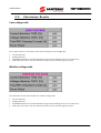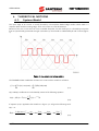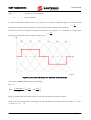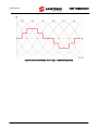
1
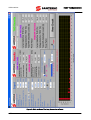
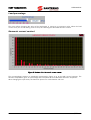
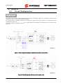
• 16B2011B1 •
EASY HARMONICS
USER MANUAL
Issued on 03/08/09
R.00
English
• This manual is integrant and essential to the product. Carefully read the instructions contained herein as
they provide important hints for use and maintenance safety.
• The software described in this manual is a tool helping the design of inverters. Elettronica Santerno is
not responsible for any direct and/or consequential damages due to the implementation of the Easy
Harmonics.
• Elettronica Santerno reserves the right to make any technical changes to this manual and to the software
without prior notice. If printing errors or similar are detected, corrections will be included in the new
releases of this manual.
• Elettronica Santerno is responsible for the information contained in the original version of the Italian
manual.
• The information contained herein is the property of Elettronica Santerno and cannot be reproduced.
Elettronica Santerno enforces its rights on the drawings and catalogues according to the law.
Elettronica Santerno S.p.A.
Strada Statale Selice, 47 - 40026 Imola (BO) Italy
Tel. +39 0542 489711 - Fax +39 0542 489722
www.elettronicasanterno.com [email protected]
EASY HARMONICS
USER MANUAL
0.
TABLE OF CONTENTS
0.1.
Chapters
0.
TABLE OF CONTENTS ................................................................................................................ 2
0.1.
Chapters ...................................................................................................................................2
0.2.
Figures ......................................................................................................................................2
1. OVERVIEW ................................................................................................................................. 3
2. INPUT PARAMETERS................................................................................................................... 5
2.1.
Grid Data ..................................................................................................................................5
2.2.
Distorting Loads (Inverters) Data .................................................................................................6
3. DESIGN TOOLS.......................................................................................................................... 7
4. RESULTS................................................................................................................................... 10
4.1.
Circuit Configuration............................................................................................................... 10
4.2.
Calculation Results .................................................................................................................. 12
4.3.
Calculated Plant Data ............................................................................................................. 13
5. MENU BAR ............................................................................................................................... 14
5.1.
File Menu ............................................................................................................................... 14
5.2.
Help Menu.............................................................................................................................. 15
6. THEORETICAL NOTIONS ......................................................................................................... 16
6.1.
System Model ......................................................................................................................... 16
6.2.
Voltage Distortion ................................................................................................................... 19
6.3.
Power Factor........................................................................................................................... 21
7. REFERENCE STANDARDS ......................................................................................................... 23
0.2.
Figures
Figure 1: Logo of the Easy Harmonics software. ...........................................................................................3
Figure 2: Main window of the Easy Harmonics software................................................................................4
Figure 3: Readout of the harmonic current content. ......................................................................................9
Figure 4: Circuit diagram including a mains reactor and a resonant filter................................................... 10
Figure 5: Circuit diagram including a mains reactor only........................................................................... 10
Figure 6: About window........................................................................................................................... 15
Figure 7: Line current and voltage pattern. ............................................................................................... 16
Figure 8: Line current and voltage with increased conduction angle. .......................................................... 17
Figure 9: Line current/voltage when using a 12-pulse configuration. .......................................................... 18
Figure 10: Basic diagram in the delivery point........................................................................................... 19
Figure 11: Diagram showing 3 delivery points (PCC1 to PCC3). ................................................................ 20
2/23
EASY HARMONICS
1.
USER MANUAL
OVERVIEW
The power absorbed by a motor connected to an inverter depends both on the load torque and the motor
speed. Power is delivered through the conversion of the electric energy made from the inverter by transforming
the AC voltage available from the mains—with fixed frequency— into DC voltage, then into variable-frequency
AC voltage. These transformations of energy require that the power be continuously delivered to the motor. As
a result, apart from the performance of the system, an equivalent power level is absorbed by the mains with
constant voltage. Therefore, the current coming from the mains and absorbed by an inverter operating in
PWM mode is not sinusoidal and its harmonic contents are high. The active power is transferred from the 1st
harmonic only, so the current harmonics larger than the first one will be responsible only for the Joule effect
losses in the mains conductors. Knowing the harmonic contents of the current absorbed by an inverter allows
arranging the corrective actions for reducing the harmonics. The “Easy Harmonics” software is a tool for
calculating the current distortion and the voltage distortion localized in the current delivery point in a grid,
when loads are controlled by inverters. The possible corrective actions for reducing the harmonic currents are
also considered.
Figure 1: Logo of the Easy Harmonics software.
3/23
EASY HARMONICS
USER MANUAL
Figure 2: Main window of the Easy Harmonics software.
4/23
EASY HARMONICS
2.
USER MANUAL
INPUT PARAMETERS
The calculation results are processed by the Easy Harmonics software based on the parameters of the
application to be checked.
2.1.
Grid Data
The grid data varies from plant to plant. It is known by the end user but not by the manufacturer of the
equipment, and it dramatically affects the calculation results. If the input parameters are not perfectly known,
you can enter approximate values to get estimated results. The values to be entered are the following:
Nominal voltage on low voltage side
The no-load voltage value of the LOW VOLTAGE SIDE in the mains transformer. It is expressed in Volts.
Nominal power of the transformer
The nominal power of the grid transformer. It is expressed in kVA.
Transformer short circuit Vsc
The short-circuit voltage value of the grid transformer, expressed as a percentage of the rated voltage. Starting
from that value, you can calculate the transformer short-circuit current.
Power of linear loads
The overall power of non-linear and non-distorting loads (if any) supplied through the same grid transformer.
MV side value
The nominal value of the MEDIUM VOLTAGE side expressed in kV.
5/23
EASY HARMONICS
USER MANUAL
Short circuit current on MV side
The value of the expected short-circuit current on MV side. It is expressed in kA.
Frequency
The operating frequency of the system.
2.2.
Distorting Loads (Inverters) Data
Size of the inverter
The button for selecting the size of the inverter. When you click the button, a list appears showing all the sizes
of Elettronica Santerno’s inverters.
Selection of the inverter model
The button for selecting the inverter model. When you click the button, the list of the inverter codes
corresponding to the size of the inverter you have just selected appears, based on the standard application
table. The inverter power is given in the field below.
Total installed power of motor driven inverters
After selecting the size and model of the connected inverters, the total installed power is displayed.
6/23
EASY HARMONICS
3.
USER MANUAL
DESIGN TOOLS
The Easy Harmonics provides a parameter set for the design of your plant.
Pulse
The switch linked to this function allows changing the configuration of the connection of the inverter to the
grid:
•
•
“6” indicates that the inverter is supplied from the 3-phase mains with a single-winding transformer;
“12” indicates that the inverter is supplied from the 3-phase mains with a dual secondary transformer
with a vector group “Dyn11+ Dd0”. The calculation of the total current distortion THDI is based on the
current flowing in the transformer current, where the vector sum of the currents flowing in the two
secondaries is done. A double-fed inverter is required.
AC reactor
The button linked to this function allows changing the value of the grid reactor. The default value is 3%,
corresponding to the voltage drop occurring when the rated inverter current flows in the reactor. If you change
the default value, the current distortion and the voltage distortion in the delivery point is recalculated in real
time. Therefore, you can see how the grid reactor value affects the harmonic currents. The maximum
programmable value is 20%.
N. of filtered harmonics
If a resonant filter is installed, you can select the harmonic current component to be filtered. The software
automatically calculates the new harmonic contents and the value of the current distortion and the voltage
distortion. The modification of the harmonic order is independent of the ratings of the AC reactor.
Efficiency
The ratio between the mechanical power of the motors and the electrical power absorbed by the mains.
The default value is 0.91; it can be changed with the arrows.
7/23
USER MANUAL
EASY HARMONICS
DC reactor
The numeric value is the min. value of the inductance to be installed on the DC-side of the inverter so that the
measured distortion value is the same as the calculated value. If the inductive value of Ldc is lower than the
displayed value, the DC-side current takes a waveform composed of two pulses in π/3 and 2 π/3, whose width
increases when increasing the value of Ldc, and whose amplitude increases when Ldc decresaes.
The suggested value for Ldc is the value for which, when the current is 80% of the rated current, the minimum
current drops to zero in the central value (in π/2 and in 3π/2). When the current flowing is 100%, the
waveform is continuous in the range between π/6 and 5π/6. Any inductance value Ldc exceeding the minimum
suggested value makes the waveform continuous for current flowing values lower than 80% of the rated
current.
Use the cursor to change the value of Ldc. The distortion value is recalculated in real time.
8/23
EASY HARMONICS
USER MANUAL
Load percentage
The cursor allows changing the value of the load power in respect to its maximum value. When the load
current varies, the current flowing varies as well, thus affecting the calculated harmonic content.
Harmonic current content
Figure 3: Readout of the harmonic current content.
The current(voltage) spectrum is graphically represented in Figure 3 up to the 50th current harmonic. The
harmonic amplitude is given as a percentage of the amplitude of the fundamental harmonic component.
When changing the input values, the harmonic spectrum is recalculated in real time.
9/23
EASY HARMONICS
USER MANUAL
4.
RESULTS
4.1.
Circuit Configuration
The “View Circuit” button allows displaying the overall circuit diagram (Figure 4) including the position of the
components used to reduce the harmonic contents.
If a resonant filter is installed, calculation is based on the grid current and considers the contribution of the
resonant filter (Figure 4).
If a mains reactor is installed, calculation is made without considering the contribution of the resonant filter
(Figure 5).
Figure 4: Circuit diagram including a mains reactor and a resonant filter.
Figure 5: Circuit diagram including a mains reactor only.
10/23
EASY HARMONICS
USER MANUAL
AC reactor
This button allows choosing the circuit configuration in Figure 5 as a calculation model. The harmonic content
is calculated in respect to the value of Lac and Ldc.
Resonant filter
This button allows choosing the circuit configuration in Figure 4 as a calculation model. The harmonic content
is calculated in respect to the value of Lac and Ldc and to the resonant filter as well.
11/23
EASY HARMONICS
USER MANUAL
4.2.
Calculation Results
Low voltage side
This window shows the calculation results of the transformer low-voltage side:
•
•
•
•
Current distortion;
Voltage distortion;
Total RMS distorted current absorbed from the grid and including all the current harmonics;
Grid-side power factor: the ratio between the active power and the apparent power.
Medium voltage side
The calculation results of the transformer medium-voltage side:
•
•
•
•
Current distortion;
Voltage distortion;
Total RMS distorted current absorbed from the grid and including all the current harmonics;
Grid-side power factor: the ratio between the active power and the apparent power.
12/23
EASY HARMONICS
4.3.
USER MANUAL
Calculated Plant Data
The plant data based on the input data:
•
•
•
•
Grid short-circuit power (both LOW VOLTAGE and MEDIUM VOLTAGE side);
RMS value of the first harmonic current caused by the distorting load only (both LOW VOLTAGE and
MEDIUM VOLTAGE SIDE). The current values of non-distorting linear loads are not considered;
Rsce: the ratio between the grid short-circuit power and the overall power of the distorting loads in
compliance with IEC 61000-3-12;
Transformer ratio.
13/23
EASY HARMONICS
USER MANUAL
5.
MENU BAR
The Easy Harmonics software includes two menus: the File menu and the Help menu.
5.1.
File Menu
The File menu includes 5 submenus, one for each of the following functions.
•
“Open project”: opens a saved project.
•
“Save project”: saves a project.
•
“Report”: creates a report of a project as HTML.
•
“CSV Table”: creates a file with CSV extension. The CSV file contains the data related to the
current/voltage spectrum harmonic content.
•
“Exit”: quits the Easy Harmonics application.
14/23
EASY HARMONICS
5.2.
USER MANUAL
Help Menu
The Help menu includes 3 submenus, one for each of the following functions.
•
“Italian Help”: views the help manual of the Easy Harmonics in Italian.
•
“English Help”: views the help manual of the Easy Harmonics in English.
•
“About…”: displays program information and version number.
Figure 6: About window.
15/23
EASY HARMONICS
USER MANUAL
6.
THEORETICAL NOTIONS
6.1.
System Model
The input stage of an inverter is usually formed by a three-phase diode bridge rectifier whose load is a
capacitor bank and the inverting stage, which is the same as a real R resistance.
Because of this, the current line has not a sinusoidal shape but, for each half-cycle, it is formed by two pulses
that are symmetrically positioned at angle π/3 and 2π/3, whose width is established by R and C values (Figure
7).
Figure 7: Line current and voltage pattern.
The FOURIER relation establishes the harmonic content of this waveform as follows:
∞
∞
n =0
n =0
f (t ) = ∑ 2 A(n) ⋅ cos(nωt ) − ∑ 2 jB (n) sin( nωt )
(6.1)
A(n) and B(n) coefficients are calculated by means of the following equation
T
A(n) + jB(n) = F (n) =
1
f (t ) ⋅ e − jnωt dt
T ∫0
(6.2)
If equation (6.2) is applied to the waveform in Figure 7, it will give the following result:
A(n) = 0
B (n) =
16/23
2nπ
4nπ
5nπ ⎤
I1 sin(nωτ 1 ) ⎡
nπ
) − sin(
) − sin(
⋅ ⎢sin( ) + sin(
)
3
3
3
3 ⎥⎦
nπ
⎣
(6.3)
EASY HARMONICS
where
τ1
USER MANUAL
…………….. duration of the current pulse
I1 …………… current amplitude
In order to reduce the harmonic values, it is necessary to increase the conduction angle; the solution offered
by Elettronica Santerno allows reaching a maximum value of this conduction time equalling
τ1 =
π
3.
In that case, the current waveform changes and becomes as in Figure 8. It is composed of a single pulse
having an Io amplitude, and its duration increases up to
τ0 =
2π
3 .
Figure 8: Line current and voltage with increased conduction angle.
In that case, FOURIER coefficients are the following:
A(n) = 0
B (n) =
I 0 sin(nϖτ 0 ) ⎡
nπ
3nπ ⎤
⋅ ⎢sin( ) − sin(
)
nπ
2
2 ⎥⎦
⎣
Using a resonant filter for the 5th harmonic can further decrease the harmonic contents.
When a 12-pulse configuration is used (Figure 9), the only harmonics to be found are, for instance, n = 12k ±
1, where k = 1,2,…….m.
17/23
USER MANUAL
EASY HARMONICS
Figure 9: Line current/voltage when using a 12-pulse configuration.
18/23
EASY HARMONICS
6.2.
USER MANUAL
Voltage Distortion
The voltage distortion on a grid occurs when a non-sinusoidal load is applied (Figure 10). The current flowing
from the voltage generator to the non-sinusoidal load cause—in the delivery point—a voltage contribution
proportional to the product of each current harmonic amplitude multiplied by the grid impedance, calculated
at the frequency of the corresponding current harmonic.
An ideal grid has a null output impedance (Z =0); this means that in case of a short-circuit in the delivery
point, the current flowing assumes a theoretically infinite value. As this is not possible, the grid impedance in
the delivery point is not null.
The current absorbed from the grid by non-disrtorting loads can be considered as the addition of several
components, each of them is characterized by frequency and amplitude that can be calculated with the
relation in (6.1).
Figure 10: Basic diagram in the delivery point.
a) In no-load conditions (I(n) = 0), the available voltage V(n) in the delivery point equals the no-load
voltage of the generator:
V(n) = E
b) when the connected load is operating (I(n) ≠ 0), the voltage in the delivery point is as follows:
V ( n) = E − Z ( n) • I ( n)
where Z(n) is the total line impedance.
The voltage distortion factor THDV in the delivery point is defined as follows:
THDV = 100 •
Z ( n) ⋅ I ( n)
E
calculated for n>1
Note that the voltage distortion depends on the value of Z(n), i.e. it depends on the geographical location of
the delivery point.
Example. Figure 11 shows a grid with different delivery points (PCC1 or PCC2) based on the user whose
THDV value is to be checked:
19/23
USER MANUAL
EASY HARMONICS
Figure 11: Diagram showing 3 delivery points (PCC1 to PCC3).
The main power delivery is 150kV high voltage. The first common delivery point (PCC1) is downstream of the
20MVA transformer (T1) on the 20kV MEDIUM VOLTAGE grid. The other two delivery points are called PCC2
and PCC3.
The distorted current absorbed from the user connected to PCC3 will cause a voltage distortion in PCC3 and a
voltage distortion in PCC1. The voltage distortion in PCC1 could be large and cause troubles to the user
connected to PCC2. For that reason, you should calculate the contribution to the voltage distortion in PCC1—
due to the distorted current absorbed from the user connected to PCC2—separately from the contribution to
the voltage distortion due to the current distortion absorbed by the user connected to PCC3.
The total distortion in PCC1 is the sum of the two contributions.
When calculating the voltage distortion, you must know the characteristic data of the grid (power of the
transformers, short-circuit voltage, voltage level, etc.).
20/23
EASY HARMONICS
6.3.
USER MANUAL
Power Factor
The input power factor, considered from the grid side, of a system composed of a motor and an inverter is
different when the motor is supplied from the grid.
The current absorbed from the grid can have a harmonic content (more or less large depending on the
harmonic-suppressing measures being used) which “increases” the RMS value of that current and contributes
alterating the measure of the power factor.
The measure systems generally used for the cosϕ are obtained in order to measure the offset angle ϕ between
the grid voltage and the current flowing. However, because the current is strongly distorted due to the
harmonics, the measure readout is often distorted as well, and the angle measurement is incorrect. As a result,
the readout of the cosϕ is much lower than the actual cosϕ.
It can happen that the power factor does not match with the cosϕ: as a matter of fact, the power factor and
the cosϕ match only when both voltage and current are true sinusoids.
The “Total power factor” is the ratio between the active power and the apparent power;
the “cosϕ “ is the cosine of the offset angle between the voltage and the first current harmonic.
When a motor is operated by an inverter, the total power factor is strongly dependent on the harmonic
current, i.e. on the current distortion factor.
Normally, the power factor of a distorted waveform is defined as the ratio between the active power (P) and
the apparent power (VI), also considering the contributions of all the harmonic contents:
∞
∑V
k
Total power factor =
P
=
VI
⋅ I k ⋅ cos φk
k =1
∞
∑
∞
∑I
Vk2
k =1
2
k
k =1
where: Vk: RMS value of the voltage harmonic "k"
Ik: RMS value of the voltage harmonic "k"
ϕ: offset between the voltage harmonic "k" and the corresponding current harmonic.
In case of sinusoidal voltage and distorted current, the total power factor is calculated with the following
expression:
∞
Total power factor =
V1I1 ⋅ cos φ1 + V1 ∑ I k ⋅ cos φk
k =2
∞
∑I
V1 ⋅
k =1
2
k
When introducing the power factor distortion μ, that matches with the total harmonic current distortion THDI,
∞
μ = THDI =
∑I
k =2
I1
2
k
,
21/23
EASY HARMONICS
USER MANUAL
1
the total power factor becomes
1 + μ2
⋅ cos φ1
So the rectifier factor of the cosϕ is given from k =Errore. Non si possono creare oggetti dalla modifica di codici di
campo..
Example: Suppose that an inverter connected to the grid by means of AC reactor only be used;
the typical current distortion value that is measured in that case is 50%, i.e.
∞
THDI = μ =
So
∑ I k2
k =2
I1
= 50%
k = 1 + 0,5 2 = 1.118
If a real unity cosϕ is used, the total power factor is worth 0.8944 (the opposite of 1.118). On the other hand,
if you have an instrument measuring the apparent power, it is not correct to get the value of the cosϕ as the
ratio between the active power and the apparent power, because the latter is higher due to the harmonic
contribution—THDI—of the current, which is not sinusoidal.
22/23
EASY HARMONICS
7.
USER MANUAL
REFERENCE STANDARDS
The Easy Harmonics software has been developed using the calculation method and formulas prescribed by
EN 61000-3-12.
The following relations are used for calculation:
40 ⎛ I ⎞ 2
THD = ∑ ⎜⎜ n ⎟⎟
• Total current harmonic distortion:
n = 2 ⎝ I1 ⎠
•
•
•
Common connection point (PCC): the point in the grid the closest to the disturbing user, where other
disturbed users can be connected to;
Short circuit power (Ssc): the value of the three-phase short-circuit power calculated considering the
rated phase voltage “U” and impedance “Z” of the system up to the PCC:
U2
S sc =
Z
•
•
Rated apparent power of the equipment (Sequ ): value computed based on the rated line current (Iequ) of
the equipment and on phase voltage Ui
S equ = 3 ⋅ U i ⋅ I equ
•
Active power Sa: power from the first current harmonic only:
S a = 3 ⋅ U i ⋅ I1
•
Short-circuit ratio Rsce: ratio between the short-circuit power and the apparent power of the equipment.
Rsce =
•
Fundamental current of reference I1: the first harmonic current, defined as follows:
I1 =
•
S sc
S equ
I equ
1 + (THD )2
Partial weighed harmonic distortion PWHD: the ratio between the RMS value of a selected group of
harmonics starting from the 14th weighed according to harmonic order n, and the RMS value of
fundamental current I1:
⎛I
PWHD = ∑ ⎜⎜ n
n =14 ⎝ I1
40
•
2
⎞
⎟⎟ ⋅ n
⎠
Power factor PF: ratio between the active power and the apparent power:
PF =
Sa
S equ
i.e.
PF =
1
1 + (THD )2
23/23