1
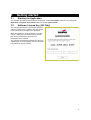
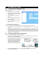
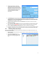
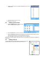
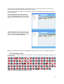
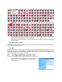
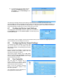
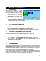
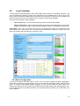
Site Installer
v2.5.29
1
Table of contents
1 Table of contents................................................................................................................................ 2
2 Installation........................................................................................................................................... 3
2.1 Removing a Previous Version...................................................................................................... 3
2.2 Installing the Software.................................................................................................................. 3
3 Getting started.................................................................................................................................... 4
3.1 Starting the Application................................................................................................................ 4
3.2 Software License Key (UK Only).................................................................................................. 4
4 Configuring a Site............................................................................................................................... 5
4.1 Creating a Site Configuration File.................................................................................................5
4.1.1 Opening an existing site......................................................................................................... 5
4.2 Retrieving a New Panel Configuration.......................................................................................... 5
4.3 Defining Detection Zones............................................................................................................. 6
4.4 Adding another Panel................................................................................................................... 7
4.5 Adding a Device........................................................................................................................... 7
4.5.1 Inserting a device................................................................................................................... 8
4.5.2 Removing a device................................................................................................................ 9
4.5.3 RF.......................................................................................................................................... 9
4.6 Configuring Device Location Text.................................................................................................9
4.7 Configuring Device Input Settings.............................................................................................. 10
4.8 Configuring Device Output Settings........................................................................................... 10
4.9 Fan Controller............................................................................................................................. 10
5 Miscellaneous features..................................................................................................................... 11
5.1 Logo upload................................................................................................................................ 11
5.2 LCD touch screen calibration..................................................................................................... 11
5.3 Log retrieval and analogue value download...............................................................................11
5.4 Firmware update........................................................................................................................ 11
5.5 Loop Calculator.......................................................................................................................... 12
5.5.1 Panel Configuration............................................................................................................. 12
5.5.2 Loop Configuration.............................................................................................................. 13
2
Installation
2.1
Removing a Previous Version
Before the software can be installed, it is recommended that you uninstall any previous versions. This can
be done by following the following steps:
1. Open the Start Menu and select Control Panel.
2. On Windows 2000/XP select Add/Remove Programs, or if using Windows Vista, select Uninstall
a Program.
3. Find the Site Installer application in the items displayed and select it.
4. Now select the Remove or Uninstall option to remove the software.
5. Windows may now ask permission to continue. If this is the case, simply confirm the action by
selecting Yes / Continue.
6.
2.2
The old version of the software will now be removed.
Installing the Software
To install the software, do the following:
1.
The software has the following software requirements
1. Microsoft .Net Framework 2.0 (.Net) or above.
2. Microsoft SQL Server Compact Edition 3.5 SP1 (SCEE) or above.
•
Only required in for versions of Site Installer v2.4.0.0 onwards.
•
The 64bit version of SSCE requires that the 32bit version be installed first.
3. Microsoft Data Access Components 2.6 (MDAC) or above.
•
Only required to open site databases created with Site Installer versions prior to v2.4.0.0.
•
Microsoft does not support MDAC on 64bit platforms.
2. Locate the file Site Installer v2.5.29.0.exe (the exact name vary depending on which edition you
have) and launch it. If the software was supplied on CD, this can be found by browsing the CD
using Windows Explorer (short-cut is Windows Key + E).
3.
The software will now install.
4.
Please follow any instructions displayed on screen.
5.
The installation of any required components (see above) is automatic and may require an internet
connection if the installers cannot be found in the current folder.
If the software has been supplied on CD, the CD should contain the installers for all of the above
prerequisites. If not, all Microsoft downloads can be found at http://www.microsoft.com/downloads/.
Without .Net installed, the application will not start.
Without the correct database subsystem installed, the application may start but will be unable to access or
create any site configuration files.
3
3
3.1
Getting started
Starting the Application
The software can either be launched from the desktop, via the Site Installer short-cut or by opening the
Start Menu | Programs | Site Installer folder and selecting Site Installer.
3.2
Software License Key (UK Only)
The first time the software is started and at specific
intervals (usually every 3 months), a screen similar
to the one shown to the right will be displayed.
When this appears, it will be necessary to contact
Cooper . Quote the code displayed and a license
key will be provided which will unlock the
functionality of the software.
The purpose of licensing the software is to prevent
unauthorised use of the software and to ensure that
it is updated at regular intervals.
4
4
Configuring a Site
4.1
Creating a Site Configuration File
To start a new site configuration, it is first necessary to create a site configuration file. This can be done by
following these steps:
1. Using the File menu select New Site.
2.
Enter a name for the site file (it is good
practice to use the same name as the site
to be configured).
3.
Select a location where the file will be
stored.
4. Now select Open to create the site file.
5.
A screen similar to the one shown on the
right will be displayed.
6.
Enter the site details into the text boxes
shown on screen.
4.1.1 Opening an existing site
Once a site configuration file has been created, you can return to it at any time in the future.
1. Using the File menu select Load Site or from the Recently used sub menu, select the file
you want.
2. If this is an old format database (Microsoft Jet / Access database with a .mdb extension) it will
be automatically upgraded to the new format (Microsoft SQL Server Compact Edition) and a
new file saved with a .sdf extension. The original file will remain unchanged. You should use
this new file from now onwards. You may if you wish keep the old file for old times sake or
delete it, as it is no longer required.
4.2
Retrieving a New Panel Configuration
To retrieve a new panel configuration, follow the steps below:
1. Open the site file if not already open (if this has not been created, refer to 3.3.1) and select
the site node in the Site overview tree.
2.
Ensure the panel has been auto-learned, refer to panel documentation if required.
3.
Connect the computer to the display card
of the fire panel using a 9-way serial cable.
This cable must include the connections
shown below. If the computer does not
have a serial port, a USB to RS232
adaptor will also be needed (see diagram):
4. Go to the Commission menu and choose Comm Port Settings. A screen like the one
shown below will be displayed:
5
5. Using the drop down box, select the
communications port that will be used to
physically connect to the panel and then
select OK. If the port you wish to use is not
available in the list please ensure that it is
correctly installed and functioning. You
may need to contact your system
administrator.
6. The Create log option can be used to create a diagnostic annotated log of the serial
communication during upload and download of commissioning data. These log files will be called
upload.log (PC to panel) and download.log (panel to PC) and placed in the same folder as the
configuration file, as chosen in section 3.3.1.
7. Place the panel into level 3 and select the Commission menu option from the menu choices
displayed on the panel.
8. Select Download CDR to Laptop from the menu choices displayed on the panel and then select
OK. This must be done BEFORE the next step, otherwise communications will not be possible.
9. Select the Retrieve Database from Panel button on the PC software (see FIGURE 2).
10. The panel configuration will now be transferred to the PC and a new panel will be added to the site
configuration. If this does not occur, double check the connections and repeat these steps again.
4.3
Defining Detection Zones
Once a new panel configuration has been retrieved, the next thing to do is to define some zones. To do
this, follow the steps below:
1.
Select the first loop of the panel in the overview window. A screen similar to the one shown below
will be displayed:
2. Now select the New Zone button. A
window will be displayed, which contains
the zones not currently assigned to the
loop.
6
3. Select each zone required (use control + left mouse button to select
multiple zones).
4. Select OK to add the zones to the loop.
5.
4.4
Repeat this for each loop.
Adding another Panel
1. Select the Add Panel button. The screen shown
below in FIGURE 7 will be displayed:
2. Enter the panel name. It is common practice to set this to the location of the panel on site.
3. Select the panel type. Selecting the wrong panel type may cause Site Installer to display incorrect
options and therefore produce an invalid configuration for the panel.
4. Now select OK to create the panel and add it to the site configuration.
Note that it is possible possible to add another panel by downloading its configuration as detailed in
section 3.3.2.
4.5
Adding a Device
To begin adding devices, it is first necessary to add the zones that will be
required. If this has not already been done, refer to section 3.3.3.
7
To add a device, select the detection zone the device will occupy. This can be found on the panel loop
shown in the site overview on the left hand side of the screen.
Once the zone has been selected, the loop editor will change to include options for selecting and inserting
devices (see below):
To add a single device at a time, select the
required device type from the drop down list of
types, select Place Device and then select each
address where a device of this type is required.
To add multiple devices of the same type at the
same time, select the device type from the drop
down list of types, select the addresses required
and then select the Apply to Selection.
Note: Any gaps between devices will be highlighted as this should not occur on a self-addressing system.
4.5.1 Inserting a device
It is also possible to insert a device into the middle of the loop, effecting increasing the address of all
devices after it.
To insert a new device between addresses 1 and 2...
8
•
The resulting gap should be filled using any of the methods described above for device
placement.
•
Auto addressing should be performed on the panel so that the new device is commissioned
correctly and all following devices are readdressed.
•
Care should be taken with cause and effect settings as it is possible to change the addresses
of many devices.
4.5.2 Removing a device
Conversely it also possible to remove a device or a gap. This is done in the same way and decreases
the address of all devices above it.
4.5.3 RF
Altering the devices on an RF loop is not possible as the commissioning must be carried on on the
panel itself. The panel must be added to your site configuration by downloading it from the panel as
described in section 4.2. You will however be able to alter zones as well as cause and effect, which
can then be uploaded to the panel as normal.
4.6
Configuring Device Location Text
There are two different ways of configuring the location text of a device:
a) To configure the text of a single device, hover the mouse
over the device in the Loop Editor and wait until the device
window appears.
9
b) To configure the text of multiple devices:
select the Text Manager button in the
Loop Editor, choose Text Manager from
the Tools menu.
The device text manager allows manual editing of device text, first use date, last intervention date,
comment AND zone name. Note that if the zone name is changed for one device, it will be changed for all
devices in that zone. It is also possible to “drag and drop” or “copy and paste” cellular data from Excel (or
similar spreadsheet package) to any columns other than zone name.
4.7
Configuring Device Input Settings
To configure the input settings of a device, right click on the device in
the Loop Editor and then select Device Inputs. This will bring up the
screen shown below.
To select which input to configure, set the input number at the top of the window. For single input devices,
such as detectors, this will always be set to one.
4.8
Configuring Device Output Settings
To configure the output settings of a device, right
click on the device in the Loop Editor and then
select Device Outputs. This will bring up the screen
shown below.
Please note that the availability of options will vary
between devices and panels, please refer the
relevant documentation for details.
Some device output settings, such as By zone,
require the allocation of input triggers. This can be
done by clicking on Allocate Devices, which brings
up the window shown below.
4.9
Fan Controller
The loop base fan controller has a
similar interface to regular device
outputs, but is customised to provide the
extra options this device supports.
Refer to the fan controller hardware
manual for the specific details on how
this device operates.
The configuration can be uploaded from
the loop device's context menu.
10
5
Miscellaneous features
5.1
Logo upload
Some panels support the setting of a custom
screen logo, such as a company logo. A suitable
logo can be uploaded from the Panel Details
window by selecting Send Logo to Panel.
1. Select the image you wish to use as the
on screen logo.
2. Site Installer will automatically convert
the format and size of the image to be
suitable for displaying on the panel. You
can adjust how it does this by altering
the Clear background and Invert image options. For complex images, it may be desirable to
make alterations to the source file before loading it.
3. Select Load Logo from PC from the Commission menu on Level 3 on the panel.
4. Click Upload on the PC.
5.2
LCD touch screen calibration
All LCD touch screens require calibration, this can be performed as follows:
1. Ensure the serial communication cable is connected and configured.
2. Select Screen calibration from the Commission menu in Site Installer.
3. During the calibration process, Site Installer will display the diagnostic output of the panel.
5.3
Log retrieval and analogue value download
Site Installer includes the functionality to download logs from panels and save them onto your
computer. The method for downloading is the same regardless of which log you want.
1. From Level 2 on the panel, select either:
a) For the panel event log: Send Log to PC
b) For the analogue values: Send analogue values to PC followed by the loop number
2. When the panel is showing Waiting for PC... choose Retrieve event log from the
Commission menu in Site Installer.
3. Enter a file name to save the log as.
4. The log will be transferred and saved.
5.4
Firmware update
It is also possible to update the panel's display firmware via its serial port. This requires you have
access to a suitable Motorola s32 or s24 file. Connect your serial cable to the panel and select
Firmware upload from the Commission menu. Site Installer will automatically negotiate and start the
upload process. The panel's display will go blank during this time and the whole process will likely
take several minutes.
DO NOT interrupt the update once it has started, it will render the panel inoperable.
In the event that the update process is interrupted inadvertently, it should be possible to restart the
process. Remove the loop cards from the main board and begin the update process as before.
Immediately and reset the panel. The upload should start after a few seconds.
11
5.5
Loop Calculator
To help diagnose potential problem areas, Site Installer also includes a loop loading calculator. This
can be accessed by selecting a panel, then selecting the Loop Calculator tab. From here you can
quickly view the estimated voltage drops and maximum current values of each loop. Any problems will
result in the green 'OK' box on the right turning red and the reason being displayed.
There are two calculation modes available:•
Use Loop Devices – This uses the actual loop devices stored in Site Installer.
•
Design / Estimation – This ignores the actual loop devices and instead allows you to quickly
design new loops and obtain an approximate estimate of what you can expect the load to be.
Please Note: This is only an estimate and does not a guarantee that certain loop configurations will
work without issue. Other factors such as physical faults, temperature variations, human errors and
more can influence the load tolerance of a panel or loop.
5.5.1 Panel Configuration
To ensure the battery calculation data is correct, you will need to update the panel configuration.
Firstly select the right type of panel product in use, then select the appropriate battery capacity after 4
years. To conform with BS5839 (British standard), you will need to select the '80%' option. The
standby and alarm times should also be provided as these greatly influence the required battery size.
If your panel supports conventional sounders, the 'Configure' button will allow you to add these via a
pop-up window.
12
5.5.2 Loop Configuration
For each device, you must select the appropriate product code which represents that device. To
generate an accurate estimate of the highest voltage drop on the loop, you must also provide the
various cable lengths and cable types for each loop. Of course it is not expected you know the exact
lengths between devices and so by using the 'Length' boxes, you can enter three approximate values
and quickly generate these lengths automatically by clicking the 'Update Devices' button. In most
installations this should be acceptable.
It is important to note that some devices, such as the Zone Monitor Unit, allow additional conventional
devices to be added to the loop. It is therefore important that this additional load information be
provided via the 'Edit' button, which will appear in the list on the affected devices.
13