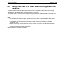
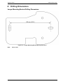
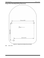
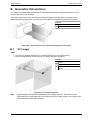
1
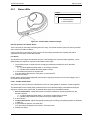
OSID Smoke Detector
Product Guide
July 2011
Document No.: 15204
Revision: A
Build: 4
Part No. LF42339
OSID by Xtralis
OSID Product Guide
Intellectual Property and Copyright
This document includes registered and unregistered trademarks. All trademarks displayed are the trademarks of
their respective owners. Your use of this document does not constitute or create a licence or any other right to use
the name and/or trademark and/or label.
This document is subject to copyright owned by Xtralis AG (“Xtralis”). You agree not to copy, communicate to the
public, adapt, distribute, transfer, sell, modify or publish any contents of this document without the express prior
written consent of Xtralis.
Disclaimer
The contents of this document is provided on an “as is” basis. No representation or warranty (either express or
implied) is made as to the completeness, accuracy or reliability of the contents of this document. The manufacturer
reserves the right to change designs or specifications without obligation and without further notice. Except as
otherwise provided, all warranties, express or implied, including without limitation any implied warranties of
merchantability and fitness for a particular purpose are expressly excluded.
General Warning
This product must only be installed, configured and used strictly in accordance with the General Terms and
Conditions, User Manual and product documents available from Xtralis. All proper health and safety precautions
must be taken during the installation, commissioning and maintenance of the product. The system should not be
connected to a power source until all the components have been installed. Proper safety precautions must be taken
during tests and maintenance of the products when these are still connected to the power source. Failure to do so
or tampering with the electronics inside the products can result in an electric shock causing injury or death and may
cause equipment damage. Xtralis is not responsible and cannot be held accountable for any liability that may arise
due to improper use of the equipment and/or failure to take proper precautions. Only persons trained through an
Xtralis accredited training course can install, test and maintain the system.
Liability
You agree to install, configure and use the products strictly in accordance with the User Manual and product
documents available from Xtralis.
Xtralis is not liable to you or any other person for incidental, indirect, or consequential loss, expense or damages of
any kind including without limitation, loss of business, loss of profits or loss of data arising out of your use of the
products. Without limiting this general disclaimer the following specific warnings and disclaimers also apply:
Fitness for Purpose
You agree that you have been provided with a reasonable opportunity to appraise the products and have made
your own independent assessment of the fitness or suitability of the products for your purpose. You acknowledge
that you have not relied on any oral or written information, representation or advice given by or on behalf of Xtralis
or its representatives.
Total Liability
To the fullest extent permitted by law that any limitation or exclusion cannot apply, the total liability of Xtralis in
relation to the products is limited to:
i. in the case of services, the cost of having the services supplied again; or
ii. in the case of goods, the lowest cost of replacing the goods, acquiring equivalent goods or having the goods
repaired.
Indemnification
You agree to fully indemnify and hold Xtralis harmless for any claim, cost, demand or damage (including legal costs
on a full indemnity basis) incurred or which may be incurred arising from your use of the products.
Miscellaneous
If any provision outlined above is found to be invalid or unenforceable by a court of law, such invalidity or
unenforceability will not affect the remainder which will continue in full force and effect. All rights not expressly
granted are reserved.
www.xtralis.com
i
OSID Product Guide
OSID by Xtralis
Document Conventions
The following typographic conventions are used in this document:
Convention Description
Italics
Used to denote: references to other parts of this document or other
documents.
Contact Us
The Americas
+1 781 740 2223
Asia
+852 2916 8894
Australia and New Zealand
+61 3 9936 7000
Europe, Middle East & Africa
+44 1442 242 330
www.xtralis.com
Codes and Standards Information for Smoke Detection
It is strongly recommended that this document is read in conjunction with the appropriate local codes and
standards for smoke detection and electrical connections. This document contains generic product
information and some sections may not comply with all local codes and standards. In these cases, the local
codes and standards must take precedence. The information below was correct at time of printing but may
now be out of date. Check with your local codes, standards and listings for the current restrictions.
AFNOR Marking
0333
Xtralis Pty Ltd.
4 North Drive, Virg. Park 236-262 East Boundary Road
Australia 3165 Bentleigh East Victoria
11
0333-CPD-075387
EN 54-12: 2012
Line Detector using an Optical Beam
Fire Safety
Product Listings
l
l
l
l
ii
UL
ULC
AFNOR
CE - EMC and CPD
www.xtralis.com
OSID by Xtralis
OSID Product Guide
Table of Contents
1
2
3
4
5
Introduction
3
1.1
1.2
3
3
Scope
Product Introduction
Detector Operation
5
2.1
2.2
2.3
5
5
9
Basic Principle of Operation
Status Annunciation
Detector Composition
Product Information
11
3.1
3.2
12
13
Dimensions
Product Specifications
Installing the Detector
15
4.1
4.2
15
18
Positioning the Detector Components
Installation Instructions
Commissioning and Maintenance
33
5.1
5.2
5.3
33
33
33
Starting Up
Acceptance Testing
Maintenance
6
Emitter Replacement and Addition
35
7
Installation Kit
37
7.1
7.2
7.3
7.4
7.5
7.6
37
38
38
39
39
40
Use of Commissioning Reflector
Changing Laser Alignment Tool Batteries
Removing OSID Emitter Battery
Use of Commissioning Test Filter
Maintenance Cleaning
Using OSID USB FTDI Cable and OSID Diagnostic Tool Software
A
Drilling Dimensions
41
B
Geometric Calculations
43
B.1
B.2
B.3
43
44
45
www.xtralis.com
10° Imager
45° Imager: 38° FOV
90° Imager: 80° FOV
1
OSID Product Guide
OSID by Xtralis
This page is intentionally left blank.
2
www.xtralis.com
OSID by Xtralis
1
OSID Product Guide
Introduction
1.1
Scope
Welcome to the OSID Smoke Detector Product Guide. This document will provide you with general product
information and detailed instructions on how to install, operate and maintain the OSID detector.
It is recommended that this product guide is read prior to installation and it is assumed that anyone using this
guide has an appropriate level of knowledge regarding fire detection systems.
1.2
Product Introduction
The OSID smoke detector provides early warning of fire by measuring the amount of smoke entering invisible
beams of light projected over a protected area.
New smoke detection technologies provide superior immunity to false alarms caused by dust and solid
objects that may interfere with the beams. Innovations in optical imaging and signal processing enable the
Imager unit to locate the Emitter unit(s) without the need for precise alignment, and compensate for natural
building shifts.
Features of the OSID system include:
l
l
l
l
l
l
l
l
l
Product range to support a variety of ranges and fields of view
Superior rejection of dust and intruding solid objects
Simple mounting and installation
Dual wavelength smoke detection
Tolerance of coarse alignment
Large adjustment and wide viewing angles
Four-wire detector interfaces
Simple user display for alarm, fault and power status annunciation
Configurable alarm thresholds
www.xtralis.com
3
OSID Product Guide
OSID by Xtralis
This page is intentionally left blank.
4
www.xtralis.com
OSID by Xtralis
2
OSID Product Guide
Detector Operation
This section provides general information on the operation of the detector, status annunciation, and the basic
composition of the system.
2.1
Basic Principle of Operation
The OSID system detects smoke by measuring the attenuation of two wavelengths of light projected from one
or more locations within an area of protection. Each OSID system consists of one Imager and up to seven
Emitters within the protected area. The Emitters are placed in the field of view of the Imager. Each Emitter
projects a wide-angled beam containing a sequence of ultraviolet (UV) and infrared (IR) light pulses toward the
Imager. The sequence of pulses is unique for each Emitter, which prevents mutual interference and enables
the Imager to reject any other unwanted light sources.
The colinear UV and IR wavelengths interact differently with small and large particles. The shorter UV
wavelength interacts strongly with both small and large particles, while the longer IR wavelength is
predominantly affected by larger particles.
Smoke particles entering a beam path will interact strongly with the shorter wavelength and cause a loss
mainly in the UV signal. The relative path loss measurement between the UV and IR signal is used to
determine if there is smoke and produce an attenuation value. If the level of attenuation caused by smoke is
higher than the preset threshold in the detector, a Fire Alarm will be reported.
In contrast, dust particles and solid intruding objects that enter the beam path cause an equal signal loss in
both wavelengths and enable the detector to identify these events as non-smoke events. If the blockage
becomes excessive, a Trouble / Fault, and not a false alarm, is reported.
An optical imaging array in the Imager provides the detector with a wide viewing angle and the ability to locate
the Emitter(s) without the need for precise alignment. This ability, combined with the wide-angled beam
projected by the Emitter, provides greater ease in installation and enables the system to compensate for the
drift caused by natural shifts in the building structure.
The system can be configured to suit a range of detection spaces by selecting the type of Imager and number
of Emitter unit(s) used in the system design. Imagers differ by the type of lens that is fitted during
manufacture. Each Imager lens has different focal characteristics that determine the operating range and the
field of view of the system - an Imager that has a longer operating range will have a narrower field of view and
vice versa. The size and geometry of the protected space will determine the Imager type, and number of
Emitters that are required for the system.
2.2
Status Annunciation
The current status of the detector is annunciated from the Imager unit through the following methods:
l
l
l
Detector Status LEDs
Initiating Device Circuit (IDC) interface
Remote Indicator interface
www.xtralis.com
5
OSID Product Guide
2.2.1
OSID by Xtralis
Status LEDs
Legend
1
Fire Alarm LED (Red)
2
Bi-color LED
l
l
Trouble (Yellow)
Normal (Green)
Figure 2-1: Status LEDs located on Imager
Normal Operation and Power Status
The bi-color LED on the Imager will flash green once every 10 seconds when the system is working normally
and is free from Troubles or Alarms.
If the bi-color LED is continuously off, the system is not properly powered and a Trouble (Fault) will be
signaled to the fire panel via the IDC interface.
Fire Alarm
The red LED on the Imager unit indicates an Alarm. The Emitter(s) from which the Alarm originates, can be
determined by the sequence of pulses as described in these steps:
1. The red LED pulses a number of times according to the Emitter number from which the Alarm
originates:
a. 'n' pulses identifies Emitter Beam 'n' as having a Fire Alarm.
b. a double pulse identifies all Emitter Beams in Alarm.
2. If more Alarms are present: 5 seconds OFF.
If no other alarms are present in the system: 10 seconds OFF.
3. Restart from Step 1.
Emitter beams are numbered sequentially from the left-to-right (from the point of view of the Imager), with '1'
as the left most Emitter beam.
Fault / Trouble Identification
The yellow color of the bi-color LED indicates if the unit is in Training Mode or if there are Trouble conditions.
The identification of the Trouble (Fault) condition and its source (Emitter/Imager) can be determined by the
sequence of pulses of the yellow LED. The identification sequence is described as follows:
1. Source identification: Yellow LED pulses according to whether the Trouble originates from the
Emitter or system:
a. 'n' pulses identifies Emitter Beam 'n' as having a Trouble (Fault) condition.
b. a double pulse identifies the system as having a Trouble condition.
2. 2 seconds OFF.
3. Trouble (Fault) Code: Yellow LED signals the fault type according to the pulsing sequences identified
in Table 2-1.
4. If more Faults are present: 5 seconds OFF.
If no other Faults are present in the system: 10 seconds OFF.
5. Restart from Step 1.
6
www.xtralis.com
OSID by Xtralis
OSID Product Guide
Example: Detector Fault (Too many Emitters have been detected)
Figure 2-2 is a representation of a system fault triggered when too many Emitters have been detected (two
pulses) and there is no other fault in the system.
Legend
A
Detector ID = double pulse
C
System fault = two pulses
B
Two seconds OFF
D
Ten seconds OFF = no other faults
Figure 2-2: Detector Fault
Example: Emitter #2 Fault (Emitter location needs to be changed)
Figure 2-3 is a representation of Emitter # 2 fault which is triggered when Emitter # 2 is either too close or too
far away from the Imager (three pulses) and there are other faults to follow.
Legend
A
Emitter #2 ID = two pulses (n)
C
Emitter fault = three pulses
B
Two seconds OFF
D
Five seconds OFF = other faults to
follow
Figure 2-3: Emitter Fault
www.xtralis.com
7
OSID Product Guide
OSID by Xtralis
Table 2-1: Trouble LED (Yellow) Trouble Conditions
Emitter / System Fault Activation Sequence
Status
-
Double Pulse every one Training Mode.
second
Emitter
One Pulse
Emitter failed, obscured or misaligned.
(One or more slow
pulses)
Two Pulses
Contamination fault. Emitter and Imager require cleaning.
Three Pulses
Emitter range fault. Emitter is either too close or too far away.
Four Pulses
Emitter type mismatch. Emitter type is not recognised by the
receiver.
Five Pulses
Emitter battery approaching end of life and needs to be
replaced at the next scheduled maintenance visit.
Note: Smoke detection continues to function while there is
sufficient residual battery power. A Trouble is signaled to the
fire panel once the battery life is exceeded.
System
Six Pulses
Imager cannot discern the signal from the Emitter beam due
to an oversaturation of light. Please check for reflections onto
the Imager, or bright light sources adjacent to the Emitter
when viewed from the Imager.
One pulse
Incorrect DIP switch configuration. Refer to section 4.2.5 for
further details.
(Double pulse)
Note: Unused DIP switches must be set to '0'.
Note:
2.2.2
Two pulses
Too many Emitters have been detected. Check the DIP switch
settings, and ensure that Emitters belonging to a different
system are not interfering with the Imager.
Three pulses
Too few Emitters have been detected. Check the DIP switch
settings and ensure that all Emitters are contained in the field
of view of the Imager. Minimise bright light sources adjacent
to the Emitter when viewed from the Imager.
Four pulses
Imager out of alignment. Check that the field of view of the
Imager is correctly aligned to all Emitters in the system.
Five pulses
Internal fault in the Imager. Imager requires replacement.
Unless otherwise noted, a Trouble is signaled to the fire panel for all System or Emitter Faults.
Initiating Device Circuit Interface (IDC)
An interface for connection to an IDC is provided for reporting the following conditions:
l
l
Fire Alarm
Trouble (Fault)
Dedicated FAULT (Trouble) and FIRE (Alarm) relay interfaces are provided on the Termination Card for
connecting to the IDC.
Separate terminals provide connections for supplying power to the detector.
2.2.3
Remote Indicator
The Termination Card provides a connection for a remote indicator that is activated when a Fire Alarm is
initiated and pulses in the same way as the Imager fire LED to signal the source of the fire.
8
www.xtralis.com
OSID by Xtralis
2.3
OSID Product Guide
Detector Composition
The OSID system consists of an Imager and up to seven Emitters. Although both components have the same
mechanical housing, Imagers are distinguished by the presence of the two status LEDs on the underside of
the device.
Legend
1
Mounting Bracket
2
Termination Card
3
Rear Case
4
Optical Surface
5
Status LEDs (Imager only)
6
Front Cover
Figure 2-4: Exploded view of an Imager or Emitter
www.xtralis.com
9
OSID Product Guide
OSID by Xtralis
This page is intentionally left blank.
10
www.xtralis.com
OSID by Xtralis
3
OSID Product Guide
Product Information
This chapter provides a summary of general, electrical and mechanical detector specifications. These
specifications apply to all currently available system configurations. The system configurations are
characterized by field of view and detection range.
Note:
Refer to your local codes and standards for compliant alarm threshold selection of various detection
ranges.
Table 3-1: Available Fields of View and Detection Ranges
Imager
Lens
Type
Usable Field of View
Horizontal
Vertical
Detection Range
Standard Power
Max.
Number of
Emitters
High Power
Min
Max
Min
Max
10°
7°
4°
30 m (98 ft)
150 m (492 ft)
--
--
1
45°
38°
19°
15 m (49 ft)
60 m (197 ft)
30 m (98 ft)
120 m (393 ft)
7
90°
80°
48°
6 m (20 ft)
34 m (111 ft)
(see note 4)
12 m (39 ft)
68 m (223 ft)
(see note 4)
7
Notes:
1. The maximum range of the Imagers are measured for the center of the Imager's Field of View (FOV).
2. The OSID laser alignment tool assists in locating the FOV for an Imager. The alignment tools can be
ordered from Xtralis. Refer to Chapter 4 for part numbers.
3. Basic calculations for FOV measurements can be found in Appendix B.
4. Angular offset from Center Field of View for Imagers. For the High Powered Emitter, the ranges are
double the values in Table 3-2.
Table 3-2: Angular offset from Center Field of View
www.xtralis.com
Imager
Maximum Angular Offset from
center Field of View
Maximum Range
90°
5°
34 m (111 ft.)
10°
33 m (108 ft.)
20°
32 m (105 ft.)
30°
30 m (98 ft.)
40°
27 m (89 ft.)
11
OSID Product Guide
3.1
OSID by Xtralis
Dimensions
Figure 3-1: Dimensions of the Imager and Emitter
12
www.xtralis.com
OSID by Xtralis
3.2
OSID Product Guide
Product Specifications
Table 3-3: Product Specifications
General
Alarm Thresholds (Configurable)
Low level, Medium level or High level
Alarm Latching (Configurable)
Latching / Non-latching configured via DIP switch.
Detection Range
Refer to Table 3-1 and Table 3-2 for further information.
Status LEDs (Imager)
Red: Fire Alarm; Bi-color Yellow / Green: Trouble or Normal. Refer to Section
2.2.1 for further information.
IP Rating
IP 44 for Electronics; IP 66 for Optics Enclosure
DIP Switch Configuration
(Termination Card)
Configuration for alarm thresholds, number of Emitters and alarm
latching/non-latching. Refer to Section 4.2.5 for further information.
Electrical
Imager Supply Voltage
20-30 VDC (24 VDC nominal)
Imager Current Consumption
Typical at 24 VDC: 4mA (one Emitter), 7mA (seven Emitters)
Peak at 24V during Training Mode: 27mA
Emitter Current Consumption
Externally-powered Emitter: 350mA at 24 VDC
Battery-powered Emitter1,2 : Built-in 5 Year Battery
Cable Gauge
0.2 - 4mm² (26-12 AWG)
Trouble / Fault Relay
2 A @ 30 VDC, NO-C-NC Dry Relay contacts.
Fire Alarm Relay
2 A @ 30 VDC, NO-C-NC Dry Relay contacts.
Heater Input Power
24 VDC, 16 mA (400 mW)
Environmental
Operating Temperature
-10°C to 55 °C (14°F to 131 °F)3
Humidity
10 to 95% RH Non-condensing.
Optional internal heating is provided to prevent condensation on the front
surface. Emitters do not require heaters.
Mechanical
Dimensions (WHD)
198mm x 130mm x 96mm (7.80in. x 5.12in. x 3.8in.)
Weight
Imager: 610g; Emitter (battery powered): 585g,
Emitter (wired): 535g,
Adjustment Angle
Horizontal: ± 60°; Vertical: ± 15°
Maximum Misalignment Angle
±2°
Note:
1. Battery-powered Emitter is activated automatically when the alignment mechanism is in the locked
position.
2. Trouble LED indicates that the planned battery end of life is approaching and a Trouble (Fault) is
signaled to the IDC when the battery is 13 months from the expected end of life. Smoke detection
continues to function while there is sufficient residual battery power. A failed battery cannot cause a
false alarm.
3. Product UL listed for use from 0°C to 39°C (32°F to 103°F)
www.xtralis.com
13
OSID Product Guide
OSID by Xtralis
This page is intentionally left blank.
14
www.xtralis.com
OSID by Xtralis
4
OSID Product Guide
Installing the Detector
The procedures in this chapter describe how to install the OSID detector. The design of the fire protection
system needs to be considered prior to installing the detector and should satisfy chosen protection goals while
complying with local codes and standards.
The key considerations in planning and implementing a successful installation include:
l
l
l
l
Selecting appropriate locations for mounting the detector components
Mounting and aligning the detector components
Wiring the detection system
Configuring the Imager components
The OSID Alignment Tool, used for both the Emitter and Imager units, is required. This tool is sold separately,
and is included in the Installation Kit. Please contact your local Xtralis supplier for ordering information.
l
OSID Installation Kit - OSID-INST:
After installation, the system should be powered up to initiate system Training Mode. Refer to Section 5.1 for
further information.
4.1
Positioning the Detector Components
When deciding on the placement of the detector components, select positions that:
l
l
l
l
l
l
l
Provide a stable and secure surface for mounting the Emitter and Imager
Include no obstructions between the Emitter and Imager
Ensure the system is mounted well above the head height of a person
Avoid direct sunlight into the Imager and Emitter components
Ensure Emitters for the same Imager are not placed within one meter of each other or lighting
Consider effects like stratification and other parameters that may affect the performance of the
detector (e.g. room geometry, ceiling height, ceiling shape, fuel sources and location)
Comply with spacing and location requirements for applicable codes and standards
The detector is able to work under a wide range of room lighting conditions, including complete darkness to
bright sunlight, and can allow for shifts in the building structure.
4.1.1
Spacing Requirements
The location and spacing of components of the detector system should comply with national and regional
installation codes. In any OSID system, the line of protection between the Imager and an Emitter is
recognized by many standards to be equivalent to a traditional beam detector. For areas that require multiple
lines of protection, the Emitters should be located and spaced according to the following recommendations to
provide full coverage of the protected space.
Note:
Please refer to your local codes and standards for specific spacing requirements for your region.
www.xtralis.com
15
OSID Product Guide
OSID by Xtralis
Figure 4-1: Horizontal spacing requirements - Emitters do not need to be at the same height
Figure 4-1 shows Emitter spacing requirements for rooms with flat ceilings.
Emitters should be positioned within a distance of H below the ceiling. For flat ceilings, this value is generally
between 25 to 600 mm (1 to 23.6 in.). The value of H will vary according to regional specifications, geometry
of the ceiling and specific requirements of the installation for the protected space.
Table 4-1: Mounting Distance from Ceiling for Flat Ceilings
International Standard
Distance from Ceiling (H)
NFPA72
-
AS1670.1
25 to 600 mm (1 to 23.6 in.)1
BS5839.1
25 to 600 mm (1 to 23.6 in.)2
GB50166
300 to 1000 mm (11.8 to 39.4 in.)
NFS 61.970 et R7
300 to 3000 mm (11.8 to 118 in.)
Notes:
1. AS1670.1: If the system is mounted more than 600 mm (23.6 in.) below the ceiling, the maximum
distance between beams is half the mounting height of the beam above the floor. For example, if the
mounting height is 10 m (32.8 ft), the distance between beams is 5 m (16.4 ft).
2. BS5839.1: If the system is mounted more than 600 mm (23.6 in.) below the ceiling, the maximum
distance between beams is 25% of the mounting height of the beam above the floor. For example, if the
mounting height is 10 m (32.8 ft), the maximum distance between beams is 2.5 m (8.2 ft).
16
www.xtralis.com
OSID by Xtralis
OSID Product Guide
Measured horizontally, Emitters can be spaced a maximum distance of S apart, with one half that spacing
from beams and the sidewall. The value of S varies according to local codes and standards, and is
summarized in the following table.
Table 4-2: Maximum Emitter Spacings
International Standard
Maximum Spacing (S)
NFPA72
18.3 m (60 ft)1
AS1670.1
14 m (45.9 ft)2
BS5839.1
15 m (49.2 ft)3
GB50166
14 m (45.9 ft)4
NFS 61.970 et R7
10 m (39.4 ft)5
Notes:
1. NFPA72: Peaked and sloped ceilings also require line of protection within 3 ft (900 mm) of the peak,
measured horizontally. Subsequent Emitters in both situations should be spaced according to a
smooth ceiling.
2. AS1670.1: This measurement is for Emitters placed 25 to 600 mm (1 to 23.6 in.) below the ceiling. For
Emitters placed more than 600 mm (23.6 in.) below the ceiling, the maximum spacing 'S' is reduced to
half of the distance between the Emitter and floor.
3. BS5839.1: For peaked ceilings, the Emitters need to be placed within 600 mm (23.6 in.) of the apex,
measured vertically.
4. GB50166: This value is valid for installations up to a maximum height of 20 m (65.6 ft). For installations
that have a height of greater than 20 m (65.6 ft), the maximum range is 20 m (65.6 ft).
5. To allow the Imagers to commission multiple Emitters as separate sources, a spatial separation
between Emitters of 3 degrees for the OSI-45, and 5 degrees for the OSI-90, is required.
www.xtralis.com
17
OSID Product Guide
4.2
OSID by Xtralis
Installation Instructions
The Emitter and Imager components of the detector can be secured to a stable surface either directly or with
the supplied mounting brackets. When mounting the Emitter and Imager units, please follow these steps:
1. Prepare the units for mounting. Refer to Section 4.2.1 for further information.
2. Secure the units to the mounting surface either directly, or with mounting brackets.
Always install the Imager first, and locate the Emitters within the Imager field of view.
3.
4.
5.
6.
a. If installing the unit via mounting brackets, follow these steps (see Section 4.2.2):
i. Install the mounting bracket and appropriate fasteners.
ii. Attach the rear assembly of the unit onto the mounting brackets.
b. If installing the unit directly onto the mounting surface, follow these steps (see Section 4.2.3):
i. Remove the Front Cover to access the mounting holes on the rear assembly.
ii. Secure the rear assembly of the unit onto the mounting surface using the mounting holes
as a template and the appropriate fasteners.
If required, wire the Termination Card (required for the Imager and externally powered Emitter).
Refer to Section 4.2.4 - Imager Wiring Connections.
Refer to Section 4.2.8 - Emitter Wiring Connections.
If required, re-attach the Front Cover after the rear assembly has been secured.
Manually align the Emitter to the Imager and vice versa. Refer to Section 4.2.10 - Coarse Alignment.
In extreme environments where the detector may suffer severe impacts, the front ball can be further
secured by applying a small amount of cyanoacrylate adhesive (e.g. Super Glue) into the hole (1) on
the outer locking ring of the ball mechanism. The Front Cover needs to be removed, the adhesive
applied and the cover re-attached.
Figure 4-2: Apply Adhesive to Outer Locking Ring
18
www.xtralis.com
OSID by Xtralis
4.2.1
OSID Product Guide
Unit Preparation
Detach the mounting brackets from the main assemblies.
In the case of the Imager, externally-powered Emitter, or if directly mounting the unit to the mounting surface,
also carefully detach the Front Cover by using a flat-blade screwdriver to gently lever the front cover away
from the main assembly.
Figure 4-3: Remove front cover with a flat blade screwdriver
Determine the cable entry points to the termination card and remove the cut-outs (if required) by using a sharp
blade to cut around the circular discs. Take care not to damage the termination card or optical components.
Cable glands can be fitted to enable cable entry through the top of the unit.
Legend
1
Cable cut-outs
2
Mounting bracket
Figure 4-4: Cable glands and cut-outs on the back and top of the Imager main assembly.
Note:
Please take appropriate precautions when working at unsafe heights. The use of elevating platforms
rather than ladders is highly recommended, particularly as both hands are required to be used during
the installation.
www.xtralis.com
19
OSID Product Guide
4.2.2
OSID by Xtralis
Securing via Mounting Brackets (preferred method)
Note:
This section only applies for components secured via mounting brackets. Ensure that the Imager is
mounted first, and Emitters are within the field of view of the Imager.
Fixing the Mounting Brackets
Secure the mounting bracket to the mounting surface, using the screw holes as a template and appropriate
fasteners for the surface type. When screwing in the mounting plate, it is recommended that star washers are
used to prevent the mounting brackets slipping.
Figure 4-5: Securing the mounting brackets with screws and star washers
The brackets are provided with one vertical and one horizontal slot to facilitate mounting if the drilled holes are
difficult to position accurately, such as on a rough brick surface. Ensure that the mounting bracket is straight
and sits flush on the surface. If considered necessary by the installer, extra screws can be fitted through the
round holes provided in the mounting plate, to ensure that the plate cannot slip on the mounting surface.
Securing to the Mounting Brackets
Legend
A
A
Mounting Bracket Locking Mechanism
Figure 4-6: Mounting the rear assembly of the unit to the Mounting Bracket
Notes:
l
l
20
When mounting the Imager units onto the brackets, ensure that the ribbon cable at the back of the front
ball does not get caught between the unit and the bracket, as movement of the front ball may pull the
ribbon cable out of the connectors.
To remove the unit from the Mounting Bracket, open the front cover and with a screwdriver push the lip
shown in Figure 4-6 backwards to then slide the unit up to detach from the Mounting Bracket.
www.xtralis.com
OSID by Xtralis
4.2.3
Note:
OSID Product Guide
Securing Directly to the Mounting Surface
This section applies to units fixed directly to the mounting surface. Ensure that the Imager is
mounted first, and Emitters are within the field of view of the Imager.
To affix the unit directly to the mounting surface, carefully make holes in the enclosure in the positions
indicated below in Figure 4-7. Take care not to damage components inside the unit.
Secure the rear assembly of the unit to the mounting surface using the mounting holes as a template and the
appropriate fasteners. Please ensure that the units sit level on the mounting surface.
Figure 4-7: Direct mounting for the rear assembly of the unit
www.xtralis.com
21
OSID Product Guide
4.2.4
OSID by Xtralis
Imager Wiring Connections
This section describes the wiring and DIP Switch configuration for the Termination Card in the Imager.
Caution:
Ensure that all wiring is in compliance with all applicable local codes and standards.
The Termination Card provides the following connections:
l
l
l
l
l
Fire Alarm and Fault (Trouble) relay terminals
External Reset input
Detector power supply
Remote Indicator output
Internal Heater power supply
A representation of the Termination Card for the Imager is shown in the following diagram.
Legend
1
Fault (Trouble) relay outputs
2
Fire (Alarm) relay outputs
3
External Reset input
4
Power supply input
5
Fire LED (Remote Indicator)
output
6
Internal Heater power supply
input
7
Configuration DIP Switch
Figure 4-8: Termination Card for the Imager
22
www.xtralis.com
OSID by Xtralis
4.2.5
OSID Product Guide
DIP Switch Settings
0
1
1
ON
SW1
2
3
4
5
6
7
8
9
10
Figure 4-9: DIP Switch
Table 4-3: DIP Switch Configuration Settings
A. Fire Alarm Thresholds
(Switch no. 1 & 2)
B. Number of Emitters
(Switch no. 3, 4 & 5)
00
Not Configured (Trouble/Fault signaled)
10
Low (Highest Sensitivity)
01
Medium (Medium Sensitivity)
11
High (Lowest Sensitivity)
000
Not Configured (Trouble/Fault signaled)
100
1 Emitter present
010
2 Emitters present
110
3 Emitters present
001
4 Emitters present
101
5 Emitters present
011
6 Emitters present
111
7 Emitters present
C. Alarm Latching
(Switch no. 6)
0
Non-latching
1
Latching
D. Dust Rejection
(Switch no. 7)
0
Disabled
1
Enabled (Increased tolerance to dust events resulting in
fewer Faults signaled)
E. Enhanced Mode
(Switch no. 9)
0
Disabled (EN54-12 Approved 6dB Alarm enabled)
F. Not Used
(Switch no. 8 &10)
www.xtralis.com
for UL 268 Approved units, set to 0
1
Enabled (Not EN54-12 approved. Object intrusion
producing 6dB attenuation gives a Fault instead of
Alarm)
0
Unused DIP switches should be set to 0
23
OSID Product Guide
4.2.6
OSID by Xtralis
External Reset
The RESET terminals enable an external signal to unlatch the system Alarms.
The system is unlatched when a voltage of 5 to 32 VDC is detected at the terminal for a period of at least
350ms or more.
The system Alarms are also unlatched when there is a power loss to the Imager of greater than 5 seconds.
Legend
1
External reset input
Figure 4-10: Connection for externally resetting the system.
The system also resets when there is a power loss to the Imager.
4.2.7
Fault and Fire Relay Terminals
Fault (Trouble) and Fire (Alarm) relays are provided on the Termination Card.
The FAULT relay is energized during normal operation while the FIRE relay is only energized when a Fire is
detected. The operation of the relays are summarized in the following table:
Table 4-4: Fault and Fire Relay Operation
FIRE Relay
FAULT Relay
Normal Operation
(Energized)
Fault
Normal Operation
(De-energized)
Fire
Four-wire Detector Connections
The Termination Card provides FIRE and FAULT relay terminals for the Initiating Device Circuit (IDC) wiring,
and POWER terminals for external power supply connections.
Some typical wiring connections for the detector can be seen in the following diagrams.
The specifications of the End-Of-Line-Device (EOLD) and series resistor for the FIRE relay connection will
vary according to the fire panel to which the detectors are connected.
24
www.xtralis.com
OSID by Xtralis
OSID Product Guide
Legend
1
Loop / IDC and Power
Connections from Fire Alarm
Control Panel (FACP) or previous
detector
2
Loop / IDC Connections to next
detector, EOLD or return path
back to the FACP
3
Power Connections to next
detector
4
Series Fire relay resistor
Schematic Symbols
Internal connections
Installer wiring connections
Terminal point
Resistor
Figure 4-11: Four-wire connections with Fault (Trouble) relay terminals connected in series between
detectors. (A) shows the connections required for wiring the terminal blocks, (B) shows a schematic
representation of the wiring.
The IDC in Figure 4-11 can be connected to the next detector, an EOLD, or may be returned back to the fire
alarm control panel (if supported).
An IDC that is looped back provides a redundant connection to ensure that all devices have an alternate path
for communications (for example, when a device fault relay is activated).
www.xtralis.com
25
OSID Product Guide
OSID by Xtralis
The next wiring diagram demonstrates a way of connecting the system so that the activation of a fault relay
will not interfere with the communications of any other device on the IDC.
Schematic Symbols
Internal connections
Terminal point
Installer wiring connections
Resistor
Legend
1
Fire Alarm Control Panel
3
Series Resistor
2
Detectors
4
EOLD: End of Line Device
Figure 4-12: Wiring Diagram with Fault (Trouble) relay terminals connected in parallel to main IDC.
(A) shows terminal block wiring, (B) shows a schematic representation of the wiring.
26
www.xtralis.com
OSID by Xtralis
OSID Product Guide
Analog Addressable Input Module Connection
An example for wiring analog addressable input modules may be found in the following diagram.
Legend
1
Fire Alarm Control Panel
2
Analog addressable input modules
3
Detectors
Figure 4-13: Wiring diagram for connecting analog addressable input modules
Relay configurations for NO or NC contacts should be made according to the control panel manufacturer's
specifications.
Power for the detector may be taken from the loop (IDC) if the panel is approved for use with the OSID
system. If not, then power should be taken from an external power source or from the Auxiliary power output
from the control panel. Refer to the control panel's specifications before using the Auxiliary power output.
Remote Indicator
A Remote Indicator can also be connected to the detector via the + and - pins on the FIRE LED interface.
Figure 4-14: Example wiring for a Remote Indicator
The LED output is suitable for direct connection to a RED LED and will supply 17mA nominal.
www.xtralis.com
27
OSID Product Guide
OSID by Xtralis
Heater
An internal heater rated at 400mW for a nominal voltage of 24 VDC is provided to prevent condensation in the
detector optics. To power the heater, a 24 VDC external power supply may be connected to the HEATER
terminals. These pins are not polarity sensitive.
Legend
1
Internal Heater
2
24 VDC External Power Supply
Figure 4-15: Example wiring for Internal Heater
4.2.8
Emitter Wiring Connections
This section describes the wiring for the Termination Card in Emitters that are powered by an external power
supply. The battery-powered Emitter component does not require connections to any other device.
Caution:
Ensure that all wiring is in compliance with all applicable local codes and standards.
Representations of the Termination Card and wiring for the Emitter are shown in the following diagrams.
J1
+Vin
- Vin
+Vout
-Vout
Figure 4-16: Termination Card for the Emitter
+
POWER
-
+
+
Vin
Vin
-
-
+
Vin
-
+
+
+
Vout
Vout
Vout
-
-
-
Legend
1
Fire alarm control panel or approved power supply
2
Detector
Figure 4-17: Wiring diagram for externally powered Emitters
Power can be taken from an external power source or from the Auxiliary power output of the control panel.
Refer to the control panel's specifications before using the Auxiliary power output.
28
www.xtralis.com
OSID by Xtralis
4.2.9
OSID Product Guide
Re-secure the Front Cover
After the wiring has been completed, re-secure the front cover to the rear assembly by engaging the left-hand
straight edge (1) and then engaging the curved edge (2).
Figure 4-18: Re-attach the Front Cover of the unit
www.xtralis.com
29
OSID Product Guide
OSID by Xtralis
4.2.10 Coarse Alignment
Once the Imager and Emitter units have been mounted, the optical spheres must be manually adjusted to
align the Emitter and Imager within the coarse limits shown in the following diagrams.
Legend
1
Emitter
2
Imager
Figure 4-19: Alignment guidelines for 10° Imager to Emitter
Note:
Emitter alignment follows the same guidelines as 10° Imager alignment. The Emitter must be
positioned with the Laser Alignment Tool to within D/120 of the Imager, where D in Figure 4-19 is the
distance between the Emitter and Imager.
Legend
1
Emitter
2
Imager
19
38
Figure 4-20: Alignment guidelines for the 45° Imager to Emitter
30
www.xtralis.com
OSID by Xtralis
OSID Product Guide
Legend
1
Emitters
2
Imager
48
80
48
Figure 4-21: Alignment guidelines for the 90° Imager to Emitter
Manual alignment of the system is easily achieved by using the OSID Laser Alignment Tool. The alignment
tool can be ordered from Xtralis. To align the Emitter to the Imager using the laser alignment tool, please follow
these steps:
Warning:
The laser alignment tool incorporates a 635-655 nm laser with an average power less than
5 mW. Avoid exposure from the laser radiation emitted by the alignment tool.
Caution:
Do not rotate the laser alignment tool beyond 1/4 turn as excessive force may cause internal
damage.
Emitter or 10° Imager Alignment
1. Switch ON and insert the laser alignment tool (1) into
the alignment hole (2).
2. Use the laser tool to move the optical sphere (3) until
the laser beam is pointing towards an area within the
specified limits as shown in Figure 4-19.
3. Rotate the tool 90° clockwise to lock the sphere into
place. A STOP position will be felt when locked. This
will also activate the Emitter.
4. After locking the Emitter/Imager, confirm the
alignment.
5. Remove and switch OFF the laser tool.
Figure 4-22:
45° Imager or 90° Imager Alignment
1. Switch ON and insert the appropriate laser alignment
tool (1) into the alignment hole (2).
2. Use the laser tool to move the optical sphere (3) until
the laser beam is pointing at a position in the
gravitional centre of all Emitters in the system as
shown in Figure 4-20 and Figure 4-21.
3. Rotate the tool 90° clockwise to lock the sphere into
place. A STOP position will be felt when locked.
4. After locking the Imager, confirm the alignment.
5. Remove and switch OFF the laser tool.
Figure 4-23:
www.xtralis.com
31
OSID Product Guide
OSID by Xtralis
This page is intentionally left blank.
32
www.xtralis.com
OSID by Xtralis
5
OSID Product Guide
Commissioning and Maintenance
5.1
Starting Up
After installing the detector, it is necessary to initiate Training Mode to allow the system to learn the locations
of the Emitters and specific characteristics of the installation. Follow these steps to initiate Training Mode:
1. Ensure that all Emitters are activated. Battery-powered Emitters are activated automatically by locking
the optical sphere in place, while externally powered Emitters activate after locking-in and powering the
unit as described in Section 4.2.10.
2. Apply power to the Imager to initiate Training Mode.
After powering-up the Imager, the Imager automatically searches for Emitters in its field of view to record their
position and timing. During this time the Trouble LED on the Imager will indicate that the detector is in Training
Mode.
Training Mode takes a maximum of 10 minutes before the detector either enters normal operation or reports a
Trouble (Fault).
Note that after a power failure to the system (lasting 10 seconds or more), the system will re-initiate Training
Mode. During power-up, the Fire relay will be in the non-fire states; and the Fault relay will indicate fault until
commissioning has successfully completed.
5.2
Acceptance Testing
After start up, the sensitivity of the detector should be tested using a calibrated method such as a smoke test,
or inserting a special optical filter into the beam path of each Emitter. This filter can be ordered from Xtralis. To
ensure that only one Emitter is tested at a time, the filter should be placed directly in front of the Emitter.
Prior to testing, ensure that the detector is isolated and the proper fire authorities and building maintenance
personnel are notified.
Components that do not pass the sensitivity tests should be cleaned or replaced. Refer to Section 5.3 for
preventative maintenance instructions.
Note:
5.3
The OSID system will not respond to test smoke from aerosol cans nor to filters supplied with
traditional third party beam detectors, as it recognizes that these are not real smoke.
Maintenance
Although the OSID detector is highly tolerant to dust and dirt, a regular schedule of maintenance should be
implemented to ensure the best possible detector performance. Visual inspection and maintenance testing
similar to the sensitivity test performed during the commissioning process should be performed yearly or in
accordance to local codes and standards or as indicated by the Contamination fault in Table 2-1.
Preventative maintenance simply includes wiping optical surfaces using a damp lint-free cloth. Make sure that
during the cleaning of the detector its alignment remains unchanged. If the alignment was changed, it is
advised that Training Mode is re-initiated. Training Mode may be initiated by powering down the Imager for 10
seconds or more, then powering up to re-initiate system alignment.
The OSID detector has no user-serviceable parts.
www.xtralis.com
33
OSID Product Guide
OSID by Xtralis
This page is intentionally left blank.
34
www.xtralis.com
OSID by Xtralis
6
OSID Product Guide
Emitter Replacement and Addition
After the system has been installed it may be necessary to replace or add another Emitter into the system.
For replacing or adding an Emitter, please follow these steps:
1. Select an appropriate position for the Emitter, ensuring that the position complies with the guidelines
(Section 4.1).
2. Mount the Emitter in the appropriate position either by using supplied mounting brackets (Section 4.2.2)
or direct surface mounting (Section 4.2.3).
3. Wire the Emitter (if required) as shown in Section 4.2.8.
4. Manually align the Emitter to the Imager within the guidelines shown in Section 4.2.10.
5. If extra Emitters are being added to the system, the number of Emitters must be configured via the DIP
switch located on the Imager (Section 4.2.4).
6. Initiate Training Mode as described in Section 5.3.
7. Perform sensitivity tests as described in Section 5.2 to ensure the correct functioning of the detector.
www.xtralis.com
35
OSID Product Guide
OSID by Xtralis
This page is intentionally left blank.
36
www.xtralis.com
OSID by Xtralis
7
OSID Product Guide
Installation Kit
The OSID Installation Kit (OSID-INST) is used in commissioning and maintaining the correct operation of the
OSID Smoke Detector.
The kit contains the following items:
l
l
l
l
l
l
l
OSID Installation and Maintenance Manual
OSID commissioning aid (reflector)
Blu-Tack adhesive
OSID smoke simulating test filter
OSID cleaning cloth
OSID serial PC interface cable
OSID laser alignment tool, with three LR44 button cell batteries pre-installed
The following sections describe how to use each component in this kit.
7.1
Use of Commissioning Reflector
When the OSID system is installed over very large distances and in brightly lit areas, it may be difficult to see
the output laser from the OSID Laser Alignment Tool when commissioning the system. To aid in the alignment
of the Imager and Emitter, the Commissioning Aid (reflector) is provided. The reflector should be attached to
the opposing unit that is not being aligned. For example, if the Emitter is being aligned, the reflector should be
attached to the front cover of the Imager. Returning light to the user, off the reflector, from the laser alignment
tool will be brighter and make it easier to determine if the unit being commissioned has been aligned correctly.
To attach the reflector to a unit, use a suitable amount of Blu-Tack adhesive. Insert two pieces of the adhesive
through the two holes in the reflector such that the adhesive material becomes rivet shaped on both sides.
Press the reflector firmly onto the unit as shown in Figure 7-1.
Figure 7-1: Attachment of reflector onto OSID unit
Note:
A string can be connected to the reflector via the hole at the bottom so that once commissioning is
completed, the reflector can be removed from the ground by pulling on the string attached to the
reflector.
Refer to Section 4.2.10 for further information.
www.xtralis.com
37
OSID Product Guide
7.2
OSID by Xtralis
Changing Laser Alignment Tool Batteries
When the laser alignment tool is switched on to be used and no light source is emitted, the batteries need to
be replaced. The OSID Laser Alignment Tool uses three LR44 button cell batteries.
To change the batteries, unscrew the front half of the tool (1) from the back part of the alignment tool. Take out
the three existing batteries and insert the new batteries, with the positive (+) battery terminal facing out of the
laser tube. When the new batteries have been inserted, screw the two halves of the tool back together.
Legend
1
Front part of alignment tool
2
Switch part of alignment tool
Figure 7-2: Laser Alignment Tool
Notes:
l
l
7.3
Used batteries should be disposed of according to local codes and standards.
Ensure that the laser alignment tool is left switched off when not in use. A piece of adhesive tape over
the switch in the off position will ensure it does not switch on inadvertently.
Removing OSID Emitter Battery
The OSID Battery Emitter (OSE-SP) contains a Lithium Thionyl Chloride (Li-SOCl2) D-cell battery. When the
battery has been drained and the Emitter is no longer functioning, the battery must be removed from the
Emitter and disposed of according to local codes and standards.
To remove the batteries, first take the front cover off the Emitter using a flat blade screwdriver as shown in
Figure 7-3.
Figure 7-3: Remove front cover from Emitter
Using a Pozidriv No. 1 tipped screwdriver, remove the three screws on the retaining ring of the front ball. Once
the retaining ring is removed, insert a flat blade screwdriver in the slot between the two halves of the front ball
and twist the screwdriver to split the front ball in half. Unplug the battery and detach it from the adhesive tape.
Do not dispose of the battery along with general waste. Contact your local waste disposal agency for the
address of the nearest battery deposit site.
38
www.xtralis.com
OSID by Xtralis
OSID Product Guide
1
Legend
2
1
Retaining ring
2
Front ball
Figure 7-4: Emitter front ball and retaining ring
Notes:
l
l
l
l
7.4
Do not recharge, crush, disassemble, heat above 100°C (212°F), incinerate or expose the Lithium
Thionyl battery to water.
Do not attempt to open or service batteries.
Do not dispose of the battery along with general waste.
The Emitter is not allowed to be shipped in normal passenger aircraft with the battery installed .
Use of Commissioning Test Filter
After the OSID system has completed Training Mode, acceptance testing is initiated by simulating a smoke
condition to the system and verifying that an Alarm is initiated. The use of an OSID Smoke Simulating Test
Filter is the preferred method of conducting the Acceptance Test. Insert the test filter wholly in front of each
Emitter’s optical window in the OSID system. Keep the filter in place (up to 40s) until an Alarm has been
generated by the OSID Imager. When an Alarm has been generated, remove the filter from the beam path and
wait for the Imager to indicate a Normal functioning system before testing the next Emitter in the system.
Note:
Prior to Acceptance Testing, the OSID detector should be Isolated to prevent false alarms from
being signaled to the fire authorities and building maintenance personnel.
Refer to Section 5.2 for more information.
7.5
Maintenance Cleaning
Regular maintenance on the OSID detector should be performed yearly or in accordance to local codes and
standards or as indicated by the Contamination Fault. Dampen the OSID Cleaning Cloth and wipe the optical
surface thoroughly, removing all dust and contaminants, leaving a visibly clean surface. Make sure that during
the cleaning of the detector its alignment remains unchanged. If the alignment was changed, it is advised that
Training Mode is re-initiated. Training Mode may be initiated by powering down the Imager for 10 seconds or
more, then powering up to re-initiate system alignment.
Note:
Prior to cleaning, the OSID detector should be Isolated or de-energised to prevent false alarms or
faults from being signalled to the fire authorities and building maintenance personnel.
Refer to Section 5.3 for more information.
www.xtralis.com
39
OSID Product Guide
7.6
OSID by Xtralis
Using OSID USB FTDI Cable and OSID Diagnostic Tool
Software
The OSID Serial PC Interface Cable can be used to aid with commissioning of the OSID system during
Training Mode, and to diagnose any subsequent Faults in the system.
The Interface Cable is connected to the Imager via the jack plug socket on the underside of the Imager. The
USB connector end of the cable is connected to a computer’s USB port.
Notes:
l
l
l
If the cable is of insufficient length, up to two 10m active USB 2.0 extension cables can be used to
extend the length.
The cable is used in conjunction with the Xtralis OSID commissioning software called OSID
Diagnostic Tool.
Before connecting the OSID Serial PC Interface Cable to a computer, the USB drivers should be
installed. The drivers and OSID Diagnostic Tool software can be obtained from the Xtralis website,
along with software installation instructions.
Refer to Section 5.1 for further information.
40
www.xtralis.com
OSID by Xtralis
OSID Product Guide
A Drilling Dimensions
Imager Mounting Bracket Drilling Dimensions
Figure A-1: Imager Mounting Bracket Drilling Dimension
Note:
Not to scale.
www.xtralis.com
41
OSID Product Guide
OSID by Xtralis
Imager Rear Assembly Drilling Dimensions
Figure A-2: Imager Rear Assembly Drilling Template
Note:
42
Not to scale.
www.xtralis.com
OSID by Xtralis
OSID Product Guide
B Geometric Calculations
This section is intended to provide estimates for horizontal width and vertical height measurements for the
fields of view of each type of Imager.
The values listed in this section are based upon simple rectangular room geometries, with fields of view
aligned along the horizontal plane. Horizontal and vertical planes are oriented with respect to the Imager.
Legend
H
Horizontal plane
V
Vertical Plane
Figure B-1: Horizontal and vertical planes with respect to the Imager
B.1
10° Imager
Notes:
l
l
The minimum distance between the 10° Imager and Emitter (D) is 30 meters (98.4 ft).
Refer to the figure below for information on 10° Imager geometric calculation.
Legend
1
Emitter
2
Imager
D
Distance between Imager and
Emitter
Figure B-2: 10° Imager Alignment
Note:
Emitter alignment follows the same guidelines as 10° Imager alignment. The Emitter must be
positioned with the Laser Alignment Tool to within D/120 of the Imager, where D in Figure B-2 is the
distance between the Emitter and Imager.
www.xtralis.com
43
OSID Product Guide
B.2
OSID by Xtralis
45° Imager: 38° FOV
B.2.1
Horizontal Plane Measurements - FOV Width
Notes:
l
The FOV widths listed on the table below are calculated using the equation: W = L x 0.781
Room Length (L) (m)
FOV width (W) (m)
Standard Power Emitter
10 m (32.8 ft)
7.8 m (25.6 ft)
20 m (65.6 ft)
15.6 m (51.1 ft)
30 m (98.4 ft)
23.4 m (76.7 ft)
40 m (131.1 ft)
31.3 m (102.6 ft)
50 m (163.9 ft)
39.1 m (128.2 ft)
60 m (196.7 ft)
46.9 m (153.8 ft)
W
High Power Emitter
70 m (229.5 ft)
54.7 m (179.3 ft)
80 m (262.3 ft)
62.5 m (204.9 ft)
90 m (295.1 ft)
70.3 m (230.5 ft)
100 m (327.9 ft)
78.1 m, (256.1 ft)
110 m (360.6 ft)
85.9 m (281.6 ft)
120 m (393.4 ft)
93.8 m (307.5 ft)
B.2.2
D
38°
L
Figure B-3: 45° Imager Horizontal Alignment
Vertical Plane Measurements - FOV Height
Notes:
l
The FOV widths listed on the table below are calculated using the equation: H = D x 0.335
Distance between Imager
and Emitter (D) (m)
FOV height (H) (m)
D
Standard Power Emitter
10 m (32.8 ft)
3.4 m (11.0 ft)
20 m (65.6 ft)
6.7 m (22.0 ft)
30 m (98.4 ft)
10.0 m (32.8 ft)
40 m (131.1 ft)
13.4 m (43.9 ft)
50 m (163.9 ft)
16.7 m (54.8 ft)
60 m (196.7 ft)
20.1 m (65.9 ft)
H
L
Figure B-4: 45° Imager Vertical Alignment
High Power Emitter
44
19°
70 m (229.5 ft)
23.4 m (76.2 ft)
80 m (262.3 ft)
26.8 m (87.9 ft)
90 m (295.1 ft)
30.1 m (98.7 ft)
100 m (327.9 ft)
33.5 m (109.8 ft)
110 m (360.6 ft)
36.8 m (120.7 ft)
120 m (393.4 ft)
40.2 m (131.8 ft)
www.xtralis.com
OSID by Xtralis
B.3
OSID Product Guide
90° Imager: 80° FOV
B.3.1
Horizontal Plane Measurements - FOV Width
The 90° Imager will suit all rectangular room
configurations (length (L) x width (W)) as long as the
maximum distance specified between the emitter and
imager (D) is not exceeded.
Notes:
Path lengths (D) which are greater than the
ranges in the table below require High Powered
Emitters.
l
Imager
Maximum Angular Offset
from center Field of View
Maximum
Range
90°
5°
34 m (111 ft.)
10°
33 m (108 ft.)
20°
32 m (105 ft.)
30°
30 m (98 ft.)
40°
27 m (89 ft.)
W
D
80°
L
Figure B-5: 90° Imager Horizontal Alignment
B.3.2
Vertical Plane Measurements Table
Notes:
l
The FOV heights listed on the table below are calculated using the following equation:
H = D x 0.890
Distance between Imager
and Emitter (D) (m)
FOV height (W) (m)
Standard Power Emitter
D
10 m (32.8 ft)
8.9 m (29.4 ft)
20 m (65.6 ft)
17.8 m (58.4 ft)
30 m (98.4 ft)
26.7 m (87.5 ft)
34 m (111.5 ft)
30.2 m (99.0 ft)
48°
H
High Power Emitter
40 m (131.1 ft)
35.6 m (116.7 ft)
50 m (163.9 ft)
44.5 m (145.9 ft)
60 m (196.7 ft)
53.4 m (175.1 ft)
L
Figure B-6: 90° Imager Vertical Alignment
www.xtralis.com
45
OSID Product Guide
OSID by Xtralis
This page is intentionally left blank.
46
www.xtralis.com