1
REVISIONS ATTACHED AFTER
PAGE 17.
User Manual for the
HE690HPL100
Hand-Held Program Loader
Second Edition
May 19, 1998
MAN0217-02
PREFACE
5-19-98
PAGE 2
PREFACE
This manual explains how to use the Horner Electric’s Hand-Held Program Loader
Copyright (C) 1998 APG, LLC., 640 North Sherman Drive, Indianapolis, Indiana 46201. All rights
reserved. No part of this publication may be reproduced, transmitted, transcribed, stored in a retrieval
system, or translated into any language or computer language, in any form by any means, electronic,
mechanical, magnetic, optical, chemical, manual or otherwise, without the prior agreement and written
permission of Horner APG, LLC.
All software described in this document or media is also copyrighted material subject to the terms and
conditions of the Horner Software License Agreement.
Information in this document is subject to change without notice and does not represent a commitment on
the part of Horner APG, LLC.
LogicMaster 90 is a trademark of GE Fanuc.
For user manual updates, contact Horner APG, Technical Support
Division, at (317) 916-4274 or visit our web site at www.heapg.com.
PAGE 3
5-19-98
PREFACE
LIMITED WARRANTY AND LIMITATION OF LIABILITY
Horner APG, LLC. ("HE") warrants to the original purchaser that the Hand-Held Program Loader
manufactured by HE is free from defects in material and workmanship under normal use and service.
The obligation of HE under this warranty shall be limited to the repair or exchange of any part or parts
which may prove defective under normal use and service within two (2) years from the date of
manufacture or eighteen (18) months from the date of installation by the original purchaser whichever
occurs first, such defect to be disclosed to the satisfaction of HE after examination by HE of the allegedly
defective part or parts. THIS WARRANTY IS EXPRESSLY IN LIEU OF ALL OTHER WARRANTIES
EXPRESSED OR IMPLIED INCLUDING THE WARRANTIES OF MERCHANTABILITY AND FITNESS
FOR USE AND OF ALL OTHER OBLIGATIONS OR LIABILITIES AND HE NEITHER ASSUMES, NOR
AUTHORIZES ANY OTHER PERSON TO ASSUME FOR HE, ANY OTHER LIABILITY IN CONNECTION
WITH THE SALE OF THIS Hand-Held Program Loader. THIS WARRANTY SHALL NOT APPLY TO
THIS Hand-Held Program Loader OR ANY PART THEREOF WHICH HAS BEEN SUBJECT TO
ACCIDENT, NEGLIGENCE, ALTERATION, ABUSE, OR MISUSE. HE MAKES NO WARRANTY
WHATSOEVER IN RESPECT TO ACCESSORIES OR PARTS NOT SUPPLIED BY HE. THE TERM
"ORIGINAL PURCHASER", AS USED IN THIS WARRANTY, SHALL BE DEEMED TO MEAN THAT
PERSON FOR WHOM THE Hand-Held Program Loader IS ORIGINALLY INSTALLED.
THIS
WARRANTY SHALL APPLY ONLY WITHIN THE BOUNDARIES OF THE CONTINENTAL UNITED
STATES.
In no event, whether as a result of breach of contract, warranty, tort (including negligence) or otherwise,
shall HE or its suppliers be liable of any special, consequential, incidental or penal damages including,
but not limited to, loss of profit or revenues, loss of use of the products or any associated equipment,
damage to associated equipment, cost of capital, cost of substitute products, facilities, services or
replacement power, down time costs, or claims of original purchaser's customers for such damages.
To obtain warranty service, return the product to your distributor with a description of the
problem, proof of purchase, post paid, insured and in a suitable package.
ABOUT PROGRAMMING EXAMPLES
Any example programs and program segments in this manual or provided on accompanying diskettes are
included solely for illustrative purposes. Due to the many variables and requirements associated with any
particular installation, Horner APG, LLC. cannot assume responsibility or liability for actual use based on
the examples and diagrams. It is the sole responsibility of the system designer utilizing Hand-Held
Program Loader to appropriately design the end system, to appropriately integrate the Hand-Held
Program Loader and to make safety provisions for the end equipment as is usual and customary in
industrial applications as defined in any codes or standards which apply.
Note:
The programming examples shown in this manual are for illustrative
purposes only. Proper machine operation is the sole responsibility of
the system integrator.
PREFACE
5-19-98
PAGE 4
TABLE OF CONTENTS
PREFACE .......................................................................................................................................... 2
LIM ITED WARRANTY AND LIMITATION OF LIABILITY ....................................................................... 3
ABOUT PROGRAMMING EXAMPLES ................................................................................................ 3
TABLE OF CONTENTS ...................................................................................................................... 4
CHAPTER 1: INTRODUCTION........................................................................................................... 6
1.1
Product Description ...............................................................................................................6
1.2
Overview..............................................................................................................................7
1.2.1
General ..........................................................................................................................7
1.2.2
Program Upload/Download (See Figure 1.2)....................................................................7
1.2.3
Local Start/Stop of a PLC (See Figures 1.2 and 1.3) ........................................................8
1.3
Requirements.......................................................................................................................9
1.4
Specifications .......................................................................................................................9
CHAPTER 2: OPERATOR GUIDE .................................................................................................... 10
2.1
Physical Characteristics of the HE690HPL100...................................................................... 10
2.1.1
Features ...................................................................................................................... 10
2.2
Reference Tables ............................................................................................................... 11
2.3
Operational Procedures for the HE690HPL100 (See Section 1.2 for functional Overview) ...... 12
2.3.1
General ........................................................................................................................ 12
2.3.2
Upload Procedures ...................................................................................................... 12
2.3.3
Download Procedure .................................................................................................... 15
2.3.4
PLC Start Procedure ..................................................................................................... 16
2.3.5
PLC Stop Procedure ..................................................................................................... 16
APPENDIX A: PC MEMORY CARD HANDLING INSTRUCTIONS ..................................................... 17
PAGE 5
5-19-98
THIS PAGE INTENTIONALLY LEFT BLANK
PREFACE
CHAPTER 1: INTRODUCTION
5-19-98
PAGE 6
CHAPTER 1: INTRODUCTION
1.1
Product Description
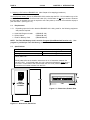
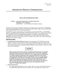
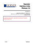
1.1.1 The Horner Hand-Held Program Loader (HE690HPL100) allows users to quickly and conveniently
upload a program from a PLC to a Flash PC Memory Card and download a program to a PLC from a
Flash Memory Card. The upload/download function requires the user to insert a Flash PC Memory Card
into the HE690HPL100 to obtain or store a program. In addition, the HE690HPL100 allows users to
locally start or stop a PLC. In such instances, the Flash PC Memory Card is not inserted in the
HE690HPL100. (See Figure 1.1.) See Appendix A for instructions regarding the use and storage of the
PC memory card.
GO LED
STATUS
PLC OK
PLC FLT
COM ERR
PC
ACTION CARD
PUSH
GO
FUNC
NO
START PLC
YES
STORE PGM
HAND-HELD
PROGRAM
LOADER
RESULT
WAIT
PASS
FAIL
PC MEMORY CARD
J1
INSERT
Flash
•
Flash PC Memory Card is inserted into
HE690HPL100 (J1) when using upload/ download
function.
•
Flash PC Memory Card removed from
HE690HPL100 (J1) when using PLC local start/stop
function.
PC Memory
Card
Figure 1.1 – Front View and Back View of HE690HPL100
(Shown with Flash PC Memory Card)
PAGE 7
1.2
5-19-98
CHAPTER 1: INTRODUCTION
Overview
1.2.1 General
1.2.1.1
a.
b.
c.
d.
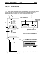
The four functions of the HE690HPL100 include:
Uploading
Program Downloading
Starting a PLC
Stopping a PLC
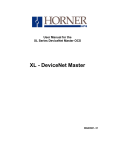
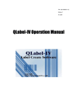
PLC Rack
Flash PC Memory Card
(used during program
upload/download only)
Serial
Cable
CPU
HE690HPL100
RS-422 serial
port
Power Supply
Module
Figure 1.2 – Overview of HE690HPL100
1.2.2 Program Upload/Download (See Figure 1.2)
1.2.2.1
The following explanation describes the program upload/download functions of the
HE690HPL100 and provides examples when each function is used.
NOTE: During the upload procedure, it is determined what type of information will be downloaded and
also where the information will be stored in the PLC (RAM or EEPROM).
a. Upload Function (See Chapter 2 for upload procedures)
Uploading refers to copying a PLC program to a Flash PC Memory Card using an HE690HPL100. The
Stop/Upload button (S2) on the HE690HPL100 is used during the upload function. S2 is located on top of
the module and unlike the Run/Download button (S1), the S2 button is not easy to access. Because the
S2 button is recessed, the user is required to use a thin probe (or a similar nonconductive object) to push
the button. (See Figure 1.3.)
Example: An Original Equipment Manufacturer (OEM) updates the software of one of its products and
needs to provide the changes to its customers. The OEM uploads the revised program from a PLC using
an HE690HPL100 to a Flash PC Memory Card. The HE690HPL100 contains a micro-processor that
stores the program to a Flash PC Memory Card. The OEM is now able to provide the updated Flash PC
Memory Card to a customer who requires the software changes.
CHAPTER 1: INTRODUCTION
5-19-98
PAGE 8
b. Download Function (See Chapter 2 for download procedures.)
Downloading refers to copying a Flash PC Memory Card program to a PLC using an HE690HPL100. The
GO or Run/Download button (S1) on the HE690HPL100 is used during the download function. S1 is
located on top of the module and is easy to access. (See Figure 1.3.)
Example: A customer receives a Flash PC Memory Card containing software updates from an Original
Equipment Manufacturer (OEM). The customer downloads the program from the Flash PC Memory Card
to the PLC using an HE690HPL100 and now has the required updates.
1.2.3 Local Start/Stop of a PLC (See Figures 1.2 and 1.3)
The HE690HPL100 allows a user to easily and conveniently start or stop a local PLC. As shown in
Figure 1.2, the HE690HPL100 is connected to the PLC via an RS-422 cable. However, the Flash PC
Memory Card is removed from the HE690HPL100 when starting or stopping the PLC.
a.
Starting a PLC with an HE690HPL100 (See Chapter 2 for starting procedures.)
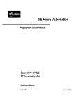
The GO or Run/Download button (S1) on the HE690HPL100 is used to start the PLC. S1 is located on
top of the module and is easy to access. (See Figure 1.3.)
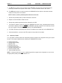
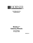
RS-422 Serial Port
Connector (P1)
(P1)
GO or Run/Download button – S1
LED
Stop/Upload button –S2
Figure1.3 – Top View of HE690HPL100 Module
Table 1.1 –Function Summary Table (S1 & S2)
Physical
Flash
Button
Function
Characteristic
PC Card
Removed
PLC Start
GO or Run/Down Load (S1)
Exposed
Inserted
Download program to PLC
Recessed
Removed
PLC Stop
Stop/ Up Load (S2)
(Access with thin probe or
Inserted
Upload program from PLC
other nonconductive object)
PAGE 9
5-19-98
CHAPTER 1: INTRODUCTION
b. Stopping a PLC with an HE690HPL100 (See Chapter 2 for stopping procedures.)
The Stop/Upload button (S2) on the HE690HPL100 is used to stop the PLC. S2 is located on top of the
module and unlike the GO or Run/Download button (S1), the S2 button is not easy to access. Because
the S2 button is recessed, the user is required to use a thin probe (or a similar nonconductive object) to
push the button. (See Figure 1.3.)
1.3
Requirements
1.3.1
Depending upon the function that the HE690HPL100 is being used for, the following equipment
and parts are required:
a. Hand-Held Program Loader:
b. RS-422 Cable:
c. Flash PC Memory Card:
(HE690HPL100)
(HE693CBL150)
(HE690PGM100)
NOTE: The Flash PC Memory Card is used for Program Upload/Download function only . One
program is provided per Flash PC Memory Card
1.4
Specifications
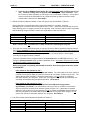
Table 1.1 - Power Draw Test for HE690HPL100 Hand-Held Programmer
Inrush
40mA @ 5Vdc
Steady State
25mA @ 5Vdc
Notes: Oscilloscopes set at 10mV/DIV and current probe set at 50 mA/DIV for
steady state level.
Steady state refers to the situation where there is no I/O interaction between the
unit and a PLC. In the Steady state, the unit is inactive and draws the least amount
of current. Inrush refers to the moment when the unit is first powered-up, and the
most amount of current is drawn from the PLC.
.991
HANDHELD
PROGRAM
LOADER
5.234
3.00
Figure 1.5 – Dimensions, Bottom View
3.314
Figure 1.4 – Dimensions, Back View
CHAPTER 2: OPERATOR GUIDE
5-19-98
PAGE 10
CHAPTER 2: OPERATOR GUIDE
2.1
Physical Characteristics of the HE690HPL100
2.1.1 Features
2.1.1.1 Before operating the HE690HPL100, the user must be familiar with HE690HPL100’s switches ,
connectors, and LED. For a description of the main features of the HE690HPL100, match the
alphabetical letters shown in Figures 2.1, 2.2, and 2.3 with the explanation that follows.
a.
b.
h.
15-pin connector (P1)
(Connects the PLC to
the HE693HPL100.)
LED
GO LED
STATUS
Run/Download
button – S1
PLC OK
c.
PLC FLT
COM ERR
PC
ACTION CARD
d.
PUSH
GO
FUNC
NO
START PLC
YES
STORE PGM
RESULT
Stop/Upload button –S2
WAIT
e.
(S2 is recessed. Use a thin probe
or similar nonconductive object.)
PASS
FAIL
Figure 2.2 – Top View of HE690HPL100
PC MEMORY CARD
f.
g.
J1 – Flash Memory Card inserted here
.991
INSERT
PC Memory
Card
Figure 2.1 – Front View of HE690HPL100
(Shown with Flash PC Memory Card)
3.00
Figure 2.3 – Bottom View of HE690HPL100
PAGE 11
a.
5-19-98
CHAPTER 2: OPERATOR GUIDE
The GO label is shown on the front panel of the HE690HPL100 and points to the Run/Download
button (S1) located on the top-side of the module . S1 is also referred to as the “GO” switch.
b. The LED label is shown on the front panel of the HE690HPL100 and points to the status indicator
located on the top-side of the module.
NOTE: Items c,d, and e provide a quick reference for the user.
c.
Denotes the possible power-up status indications of the LED.
d.
Depicts a functional table to assist the user.
e.
Denotes the possible operational results indicated by the LED.
f.
The Flash PC Memory Card is inserted into HE690HPL100 when using upload/download function.
The Flash PC Memory Card is removed from HE690HPL100 when using PLC local start/stop function.
Only one program is stored per Flash PC Memory Card (HE690PGM100).
g.
The Flash PC Memory Card plugs into J1 which is located on the bottom-side of the HE690HPL100.
h.
Shows the switches, connector and LED located on the top-side of the module.
2.2
Reference Tables
2.2.1 By default, reference tables are copied along with the program and configuration during the upload
function. The reference tables that are copied by the HE690HPL100 include:
a.
b.
c.
d.
e.
f.
g.
h.
Analog Inputs (%AI)
Analog Outputs (%AQ)
Register (%R)
Discrete Inputs (%I)
Discrete Outputs (%Q)
Discrete Temporaries (%T)
Discrete Internals (%M)
Genius Global Data (%G)
NOTE: If reference tables are not to be copied along with the program and configuration, be sure to use
the appropriate upload procedure in Section 2.3.1
CHAPTER 2: OPERATOR GUIDE
2.3
PAGE 12
Operational Procedures for the HE690HPL100 (See Section 1.2 for functional Overview)
2.3.1
2.3.1.1
a.
b.
c.
d.
5-19-98
General
The four functions of the HE690HPL100 include:
Program uploading
Program downloading
Starting a PLC
Stopping a PLC
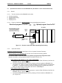
2.3.1.2
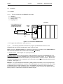
Figure 2.4 depicts the data flow direction during upload/download functions.
Download program to the PLC
Upload program from the PLC
PLC Rack
Flash PC Memory Card
(used during program
upload/download only)
Serial
Cable
CPU
HE690HPL100
RS-422 serial
port
Power Supply
Module
Figure 2.4 - Direction of Data Flow When Uploading/Downloading
2.3.2
Upload Procedures
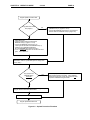
Uploading a program from a PLC (See Figure 2.5 for an Upload Procedure Flowchart)
1. Before powering-up the HE690HPL100, the user must consider the following question:
Do reference tables need to be copied along with the program and configuration data?
(General information covering reference tables is provided in Section 2.2.)
If the answer to the question is “Yes” (This is the Default):
a. Make sure that the PC card is not write-protected. Insert the Flash PC Memory Card into the
HE690HPL100 (J1). (Figure 2.1 & 2.3)
b. Connect the HE690HPL100 to the PLC by inserting an RS -422 cable into HE690HPL100
(P1).(Figure 2.2). Wait for a power-up status indication on the LED (Figure 2.2) as described
in Table 2.1. It may take a couple of seconds for HE690HPL100 do provide the power-up
status as it tries to setup communication with the PLC. Go to Step 2.
If the answer to the question is “No” :
a. Switch off the PLC.
b. Make sure that the PC card is not write-protected. Insert the Flash PC Memory Card into the
HE690HPL100 (J1). (Figure 2.1 & 2.3)
c. Connect the HE690HPL100 to the PLC by inserting an RS -422 cable into HE690HPL100
(P1). (Figure 2.2).
PAGE 13
d.
5-19-98
CHAPTER 2: OPERATOR GUIDE
Press the GO or RUN/Download button (S1) and hold down while switching the PLC to
“On.” Continue holding down S1 until the LED blinks green. Then, release S1. Wait
for a Power-up Status indication on LED (Figure 2.2) as described in Table 2.1. It may take a
couple of seconds for HE690HPL100 to provide the power-up status as it tries to setup
communication with the PLC. Go to Step 2.
2. Wait for a Power-up Status indication on the LED (Figure 2.2) as described in Table 2.1.
If the unit shows a Communications Error (solid red indication) or no status, check the
HE690HPL100’s connections and ensure that the PLC is “OK.”. When the unit shows that the unit is
ready (blinking green or orange), proceed to the next step. Note, however, that PLC faults are present
with the blinking orange indication, and the user might want to clear the faults first.
LED Color
Green
Orange
Red
Table 2.1 – HE690HPL100 Power- up Status
LED State
Meaning
Blinking
Unit ready, no PLC faults
Blinking
Unit ready, PLC faults present
Solid
Communications Error
Note: The PLC does not need to be in “Stop” mode when uploading the program.
3.
Once the unit is ready (LED blinks green or orange), the user is able to upload the program from the
PLC. Before uploading, however, the user must consider what type of PLC memory the program will
eventually be downloaded to (i.e., RAM or EEPROM). The default memory is RAM. This
consideration is important, because the upload procedure in this step (Step 3.) differs slightly
according to the type of memory selected.
There are instances when a program needs to be downloaded into the EEPROM of the PLC. It is
during the upload procedure (Step 3) that the parameter is set. As a result, all users must consider
the following question before proceeding:
When the program is eventually downloaded to the PLC, does the program need to be copied
into EEPROM?
If the answer to the question is “No”:
Simply press the Stop/Upload button (S2) and release . The user needs to use a thin probe (or
a similar nonconductive object) to press S2, because S2 is recessed. (Refer to Figure 2.2.). The
status LED will show Operation in Progress (solid orange). Do not remove PC card when
download operation is in progress. In this case, the program will be stored into RAM when it is
eventually downloaded using a download operation. Go to Step 4.
If the answer to the question is “Yes”:
Simply press Stop/Upload button (S2) and hold until LED blinks orange (takes
approximately 3 seconds). The user needs to use a thin probe (or a similar nonconductive
object) to press S2, because S2 is recessed. (Refer to Figure 2.2.) If the button is released
before the orange blink occurs, the program will not be copied into EEPROM during download.
After the orange blink, the status LED will show Operation in Progress (solid orange). Do not
remove PC card when download operation is in progress. Go to Step 4.
4. The LED provides result indications as depicted in Table 2.2.
LED Color
Orange
Green
Red
Red
Table 2.2 – HE690HPL100 Status/Result
LED State
Meaning
Solid
Operation in progress
Solid
Operation successful
Blinking
PC card fault
Solid
Communications Error
CHAPTER 2: OPERATOR GUIDE
5-19-98
PAGE 14
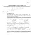
Program Upload Pr ocedure Start
Copy Reference Tables
with program?
Yes
1. Insert the Flash PC Memory Card into the
HE690HPL100 (J1). (Figure 2.1 & 2.3)
2. Connect the HE690HPL100 to the PLC by inserting an
RS-422 cable into HE690HPL100 (P1) (Figure 2.2).
No
1. Switch off the PLC.
2. Insert the Flash PC Memory Card into the
HE690HPL100 (J1). (Figure 2.1 & 2.3)
3. Connect the HE690HPL100 to the PLC by
inserting an RS-422 cable into HE690HPL100 (P1).
4. Press the GO or RUN/Download button
(S1) and hold down while switching the PLC
to “On.” Continue holding down S1 until the LED blinks
green. Then, release S1.
Wait for a Power-up Status indication on the LED as
described in Table 2.1 (LED blinks green or orange when
unit is ready.)
Copy program into
EEPROM during
download?
Yes
Press Stop/Upload button (S2) and hold until LED blinks
orange (approximately 3 seconds). If S2 is released
before the orange blink occurs, the program will not be
copied into EEPROM during download.
No
Press the Stop/Upload button (S2) and release (Figure 2.2).
Program stored in RAM when downloaded.
Check result indications in Table 2.2.
Program Upload Procedure End
Figure 2.5 – Upload Procedure Flowchart
PAGE 15
5-19-98
CHAPTER 2: OPERATOR GUIDE
a.
5.
In case of PC card fault, ensure:
1. The PC Memory Card is an Intel, Series II compatible Flash Memory
Card with 5V DC operating voltage and 12V DC programming voltage.
2. The Flash PC Memeory Card is not write-protected.
b. In case of Communication Error:
1. Check the Program Loader – PLC connection and make sure that the PLC is ‘OK’.
2. Make sure that the PLC is not OEM Locked. (If using LogicMaster 90 [LM90], the OEM
setting is with password protection.)
Press and release the GO or RUN/Download button (S1). The HE690HPL100 then displays the
unit status (Table 2.1) and is ready for the next operation. After successful upload of the program,
write-protect the PC memory card to avoid accidentally overwriting the program . (Note that the
upload switch (S2) is recessed to avoid accidental erasure of a program on the PC memory card).
2.3.3 Download Procedure
During the upload procedure, it is determined what type of information will be downloaded and
also where the information will be stored (RAM or EEPROM).
1.
2.
3.
4.
5.
Connect the HE690HPL100 to the PLC (Figure 2.4).
Switch ON the PLC, if not already ON. Wait for the power-up status of HE690HPL100. It may take a
couple of seconds for HE690HPL100 to provide the power-up status as it tries to setup
communication with the PLC. Make sure that HE690HPL100 shows Unit Ready status (status LED
blinks green or orange). If HE690HPL100 shows Communication Error (status LED shows solid red)
or does not show any status, check the connection and ensure that the PLC is ‘OK’.
Insert the Flash PC Memory Card containing the program to be downloaded into the HE690HPL100
(J1) (Figures 2.1 and 2.3).
Note that the PLC will be automatically placed in Stop mode during the program download operation
(if not already stopped). After successful download, PLC will be placed in Run mode.
Before downloading the program to the PLC, the user will need to consider the following question:
Do the reference tables need to be cleared after successful download of the program to
the PLC?
If the answer to the question is “No” or “As decided by the OEM”:
Simply press and release the GO or Run/Download button (S1) (Figure 2.2).
This starts the Download of programs to the PLC. The status LED shows Operation in Progress
(solid orange). Do not remove the PC card when download operation is in progress.
If the Memory Card contains registers written during program upload (by the OEM), the registers
will be overwritten by the HE690HPL100 with those values during download. If the Memory Card
contains no registers written during program upload (by OEM), the registers will be unchanged by
the HE690HPL100 during download.
If the answer to the question is “Yes”:
Press the GO or Run/Download button (S1) and hold until LED blinks orange (takes
approximately 3 seconds) (Figure 2.2). If the Go button is released before the orange blink
occurs, the reference tables will not be cleared upon download.
After the orange blink, status LED shows Operation in Progress (solid orange). Do not remove
the PC card when download operation is in progress. The program and configuration on the PC
card is then stored to the PLC. In this case, after successful download, the reference tables are
cleared.
CHAPTER 2: OPERATOR GUIDE
5-19-98
PAGE 16
NOTE: The program is also copied to PLC EEPROM if the choice was made to do so
during program upload.
6.
After the program is successfully downloaded, the PLC is placed into the Run mode. The results are
described in Table 2.2.
a.
In case of PC card fault (status LED blinks red), make sure that the PC card contains valid
program data.
b. In case of Communication Error (status LED shoes solid red):
1. Check the Program Loader – PLC connection and make sure that the PLC is ‘OK’.
2. Make sure that the PLC attached is of same type (351, 313 etc.) as of the PLC used for storing
the programs to PC card.
3. If the configuration stored on the Flash Memory PC Card has passwords enabled, the PLC
passwords also need to be enabled. If they are disabled, programs will not be copied.
4. Make sure that the PLC is not OEM Locked. (If using LogicMaster 90 [LM90], the OEM setting
is with password protection.)
7. Press and release the GO or RUN/Download button (S1). The HE690HPL100 then displays the
unit status (Table 2.1) and is ready for next operation.
2.3.4 PLC Start Procedure
1.
2.
3.
4.
5.
6.
7.
8.
Connect the HE690HPL100 to the PLC (Figure 2.4).
Switch ON the PLC, if not already ON. Wait for the power-up status of HE690HPL100. It may take a
couple of seconds for HE690HPL100 do provide the power-up status as it tries to setup
communication with the PLC. Make sure that HE690HPL100 shows Unit Ready status (status LED
blinks green or orange). If HE690HPL100 shows Communication Error (status LED shows solid red)
or does not show any status, check the connection and ensure that the PLC is ‘OK’.
Ensure that the Flash PC Memory Card is removed from the HE690HPL100 (Figure 2.1).
Press and release the GO or Run/Download button (S1) (Figure 2.2). Wait for PLC faults (if any) to
clear and for the PLC to be placed in Run mode.
Check LED for result indications in Table 2.2.
In case of Communication Error (status LED shows solid red):
Check the Program Loader – PLC connection and make sure that the PLC is ‘OK’.
After displaying the operation results (Table 2.2) for a brief period, the HE690HPL100 displays the
unit status (Table 2.1) and is then ready for next operation.
2.3.5 PLC Stop Procedure
1.
2.
3.
4.
5.
6.
7.
8.
Connect the HE690HPL100 to the PLC (Figure 2.4).
Switch ON the PLC, if not already ON. Wait for the power-up status of HE690HPL100. It may take a
couple of seconds for HE690HPL100 do provide the power-up status as it tries to setup
communication with the PLC. Make sure that HE690HPL100 shows Unit Ready status (status LED
blinks green or orange). If HE690HPL100 shows Communication Error (status LED shows solid red)
or does not show any status, check the connection and ensure that the PLC is ‘OK’.
Ensure that the Flash PC Memory Card is removed from the HE690HPL100 (Figure 2.1).
Press and release the Stop/Upload button (S2). The user needs to use a thin probe (or a similar
nonconductive object) to press S2, because S2 is recessed. The PLC is placed in Stop mode.
Check LED for result indications in Table 2.2.
In case of Communication Error (status LED shows solid red):
Check the Program Loader – PLC connection and make sure that the PLC is ‘OK’.
After displaying the operation results (Table 2.2) for a brief period, HE690HPL100 displays the unit
status (Table 2.1) and is then ready for next operation.
PAGE 17
5-19-98
APPENDIX A
APPENDIX A: PC MEMORY CARD HANDLING INSTRUCTIONS
The following precautions and guidelines will help in avoiding damage to the HE690PGM100 Flash PC
Memory Card.
1.
Do not remove HE690PGM100 from the program loader HE690HPL100 when a Program Upload
or a Program Download operation is in progress.
2.
Do not use or store HE690PGM100 in conditions of extreme temperature or humidity.
3.
To ensure that the data on the HE690PGM100 is not accidentally overwritten, make sure that
HE690PGM100 is Write Protected (A Write Protect switch [located on the edge of HE690PGM100] is
provided for this purpose).
4.
When not in use, store HE690PGM100 in a dry place.
5.
Do not drop, bend or crush the HE690PGM100 PC card.
6.
Keep the connector J1 of the HE690HPL100, used for inserting the PC card clean.
MAN0217-02-A
27 JULY 1998
KEEP WITH USER MANUAL
27 July 1998
Revision pages for
Horner Electric’s Hand-Held Program Loader User Manual
HE690HPL100, Second Edition
Attached to this cover page is a revision for the Horner Electric’s Hand-Held Program Loader
User Manual dated 19 May 1998. (MAN0217-02)
THESE REVISED REQUIREMENTS ARE NOW IN EFFECT.
New and revised pages may be issued periodically. For user manual updates, please contact
Horner Electric Advanced Products Group, Technical Support Division, at (317) 916-4274 or visit
our website at www.heapg.com.
Revision Key
Changes to text, tables or graphics contained in the attached
revision are indicated as follows:
1. Added text is underlined.
2. Deleted text is lined through.
3. New, revised, or deleted items are specified as such in ( ).
List of Effective Pages
The most current user manual consists of the following list of effective pages including
the attached revision pages: * Denotes new or revised pages
Page
Date
Front Cover………………………….……………….Contained in MAN0217-02 dated 19 May 1998
2 - 6……………………………………….…….…….Contained in MAN0217-02 dated 19 May 1998
*7…………………..……….…………………………………….Revision Pages dated 27 July 1998
8……….…………………………………………..…..Contained in MAN0217-02 dated 19 May 1998
*9…………………..……….…………………………………….Revision Pages dated 27 July 1998
10 -17…………………………………….…….….….Contained in MAN0217-02 dated 19 May 1998
PAGE 7
27 JULY 1998
1.2
CHAPTER 1: INTRODUCTION
Overview
1.2.1
General
1.2.1.1 The four functions of the HE690HPL100 include:
(REVISED)
a.
b.
c.
d.
Program Uploading
Program Downloading
Starting a PLC
Stopping a PLC
(Item a revised 27 July 1998)
PLC Rack
Flash PC Memory Card
(used during program
upload/download only)
Serial
Cable
CPU
HE690HPL100
RS-422 serial
port
Power Supply
Module
Figure 1.2 – Overview of HE690HPL100
1.2.2
Program Upload/Download (See Figure 1.2)
1.2.2.1 The following explanation describes the program upload/download functions of the
HE690HPL100 and provides examples when each function is used.
NOTE: During the upload procedure, it is determined what type of information will be downloaded
and also where the information will be stored in the PLC (RAM or EEPROM).
a.
Upload Function (See Chapter 2 for upload procedures)
Uploading refers to copying a PLC program to a Flash PC Memory Card using an HE690HPL100. The
Stop/Upload button (S2) on the HE690HPL100 is used during the upload function. S2 is located on
top of the module and unlike the Run/Download button (S1), the S2 button is not easy to access.
Because the S2 button is recessed, the user is required to use a thin probe (or a similar
nonconductive object) to push the button. (See Figure 1.3.)
Example: An Original Equipment Manufacturer (OEM) updates the software of one of its products
and needs to provide the changes to its customers. The OEM uploads the revised program from a
PLC using an HE690HPL100 to a Flash PC Memory Card. The HE690HPL100 contains a microprocessor that stores the program to a Flash PC Memory Card. The OEM is now able to provide the
updated Flash PC Memory Card to a customer who requires the software changes.
PAGE 9
b.
27 JULY 1998
CHAPTER 1: INTRODUCTION
Stopping a PLC with an HE690HPL100 (See Chapter 2 for stopping procedures.)
The Stop/Upload button (S2) on the HE690HPL100 is used to stop the PLC. S2 is located on top of
the module and unlike the GO or Run/Download button (S1), the S2 button is not easy to access.
Because the S2 button is recessed, the user is required to use a thin probe (or a similar
nonconductive object) to push the button. (See Figure 1.3.)
1.3
Requirements
(REVISED)
1.3.1
a.
b.
c.
Depending upon the function that the HE690HPL100 is being used for, the following
equipment and parts are required: The HE690HPL100 requires the PLC processor to be a
version 5.01 or greater.
(Paragraph 1.3.1 revised 27 July 1998)
Hand-Held Program Loader:
RS-422 Cable:
Flash PC Memory Card:
(HE690HPL100)
(HE693CBL150)
(HE690PGM100)
NOTE: The Flash PC Memory Card is used for Program Upload/Download function only . One
program is provided per Flash PC Memory Card
1.4
Specifications
Table 1.1 - Power Draw Test for HE690HPL100 Hand-Held Programmer
Inrush
40mA @ 5Vdc
Steady State
25mA @ 5Vdc
Notes: Oscilloscopes set at 10mV/DIV and current probe set at 50 mA/DIV for
steady state level.
Steady state refers to the situation where there is no I/O interaction between the
unit and a PLC. In the Steady state, the unit is inactive and draws the least amount
of current. Inrush refers to the moment when the unit is first powered-up, and the
most amount of current is drawn from the PLC.
.991
HANDHELD
PROGRAM
LOADER
5.234
3.00
Figure 1.5 – Dimensions, Bottom View
3.314
Figure 1.4 – Dimensions, Back View