1
Appendix. Getting Started
1. Edit a Main Screen A-1
1-1. Create a main screen A-1
1-1-1. Create a Touch Tag A-2
1-1-2. Create a Numeric Tag A-5
1-1-3. Create a Lamp Tag A-7
1-2. Simulation A-9
2. Edit a Link Editor A-12
3. Edit a Project Manager
A-14
4. Setup a PMU hardware A-16
5. Edit a Program in PLC
A-19
6. Cable Connection for serial Interface A-20
Appendix. Getting Started
1. Edit a main screen
1-1. Create a main screen
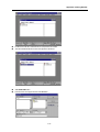
When you install PMU-MASTER software, 6 kinds of file managers will be created in Program group of Start menu.
!
Select Project Manager in the PMU-MASTER Program group.
!
Select PMU type and click OK button. (This dialog box will be appear when you select File - Change PMU Type menu)
!
Select Editor-Screen Editor in the full down menu to create a drawing file.
A-1
Appendix. Getting Started
1-1-1. Create a Touch Tag
!
Select Call Library in Draw menu to insert a button.
A-2
Appendix. Getting Started
!
Double-click or Select a button and click LOAD button.
!
Select Tag Insert-Touch in the full down menu.
!
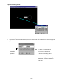
Place the touch tag direction icon on the left upper position of the button as the above and click a mouse.
Then, Touch Tag dialog box appears.
!
After entering a name of the Touch Tag, click Data button.
You can setup the condition of Operation, Buzzer and others in this dialog box.
!
Click Add button in the Touch Group dialog box.
!
Click Bit button(You can select Bit, Word or Special button)
A-3
Appendix. Getting Started
Tag Name : The initial letter begins as ‘T’ and you can enter the name up to 5 characters(English, Numeric
number) including initial letter.
!
Enter buffer number and bit position of selected buffer. Then select operation method.
User defined buffer number begins from 40(to 1024). (Please refer to User’s Manual – [Appendix A-3])
This buffer number should be matched with PLC memory address. To communicate with PLC, you need to setup
the Link Editor in the Project manager.
!
Click OK button.
!
Select the territory to be touched with dragging the mouse button.
A-4
Appendix. Getting Started
1-1-2. Create a Numeric Tag
This tag indicates the value of the system’s buffer data at the actual time on the screen of the main machine.
!
Select Tag Insert-Numeric in the full down menu.
!
Move a cursor to the place to be created and click a left mouse button.
!
Enter the Tag Name and define a buffer address(from 40 to 1024: Be sure not to overwrite the buffer address with other
tags)
!
When it is in Decimal, it indicates a maximum of 10 digits and when it is in BCD or HEX, it indicates a maximum of 8
digits.
The two methods of indicating the data are by absolute value and in relative value.
When the indication method is of relative value, and the specified buffer data goes beyond the top inch and bottom
inch, it will flicker.
You can determine the indicated data’s decimal point position.
!
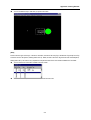
Select Data Form as Absolute type, Data Type as Signed DEC16bit, Indication digit as ‘5’ and Decimal point as ‘0’.
!
After setting up the configuration, click OK button.
If you enter the data ‘-12345’ in buffer 41, the numeric tag will be displayed in the simulation or run mode as below.
If the data type is Signed Decimal 16bit or Signed Decimal 32bit, the total indication place is actually one place more
than the Digit number.
Example)
Data type Decimal signed 16bit, Digit Number 8
A-5
Appendix. Getting Started
! By double clicking the tag to edit on the editor screen, you can edit the already created tag.
[Note]
To move a tag, select this icon.
To copy a tag, select this icon.
To cut(delete) a tag, select this icon.
A-6
Appendix. Getting Started
1-1-3. Create a Lamp Tag
According to the condition of the specified bit in the specified buffer, the specified color changes by the lamp.
!
Select Circle icon on the toolbox to draw a circle.
!
Draw a circle by dragging a mouse with pressing a left button.
!
After selecting the territory to be drawn, drop the mouse button.
A-7
Appendix. Getting Started
!
Select Tag Insert-Lamp in the full down menu.
!
Move a mouse on the circle and click the left button.
!
Select Lamp Type, Color, Attribute and others.
!
Click OK button.
A-8
Appendix. Getting Started
1-2. Simulation
You can simulate the edited screen in the computer before you download this file to PMU main machine.
You should save the created screen as a file before the simulation.
The name of the main screen should be saved as number from 1 to 999.
To confirm the contents of file, It’s better to describe the contents in the description box.
* For the main screen, the file type should be saved as *.scr.
from 1 to 999
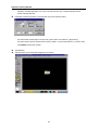
!
Select Others-Simulation in the full down menu.
!
If you want to insert a alarm file or message file, select the files in the list box.
!
Click OK button.
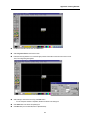
!
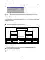
You can simulate the main screen by using the simulation tool kit (Enter Tool) or Function Keys.
A-9
Appendix. Getting Started
!
Enter the buffer number to be simulated and the value in the Enter Tool box.
!
Press Enter Key to enter the data.
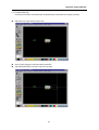
!
If you press the touch button with the mouse, the button will be activated. The value of the buffer will be changed into
‘1’.
The Status
" ‘ON’,
The status of the designated bit
Momentary
(If you setup the bit number as
Operation
‘3’ the data of the buffer(40) will be
0000-0000-0000-1000)
If you select the type of the touch tag as
Word, these 16 bits will be displayed as
Data value.
A-10
Appendix. Getting Started
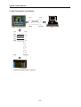
!
You can find that the lamp is ‘ON’ when you press touch button.
[Note]
Please notice the types of the tags. In the above simulation, the data of the Lamp Tag or the Numeric Tag except Touch Tag
should be sent from PLC(that is, Reading data from PLC). While, the data of the Touch Tag should be sent from PMU(that is,
Writing data to PLC). This notice is very important to setup the link editor for the communication between PLC and PMU.
!
You can view the list of the buffers created in the main screen.
!
To finish the simulation, select the Simulation Exit in the full down menu.
A-11
Appendix. Getting Started
2. Edit a Link Editor
For the communication with PLC when operating the main machine (PMU), the Link Editor allows you to enter and select the
communication method, PLC Type, Device, Address and others in the Link Table.
To use the selected Link File, Send a Link File from PC to the main machine (PMU) using Project Manager.
The extension name for the Link Select File is “.LNK”.
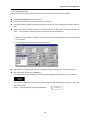
!
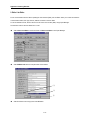
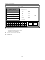
Select Others-Link Editor in the Screen Editor or Editor-Link Editor in the Project Manager.
!
Select SERIAL Link button to setup the serial communication.
!
Select PLC Series and Link type, then click OK button.
A-12
Appendix. Getting Started
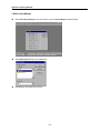
!
Enter the PLC address for the communication.
When you set a PLC address on the buffer memory area, be sure that the buffer memory is a word data.
So, M0001, R0001 are word data.
Buffer no. 40 : Touch Tag and Lamp Tag(Writing data to PLC) – Bit data(ex. M0001 card)
Buffer no. 41 : Numeric Tag(Reading from PLC) - Word data(ex. R001 card)
!
Click OK button.
!
Select File – Save menu
!
Select folder to be saved and enter file name, then click OK button.
A-13
Appendix. Getting Started
3. Edit a Project Manager
!
Select Others-Project Manager in the Screen Editor or Open the Project Manager in PMU-MASTER.
!
Select Make project file button and click OK button.
!
Click OK button after setting up the directory.
A-14
Appendix. Getting Started
!
Double click on the file to insert the file into a project file to be created.
!
Then the selected file will be moved to the right box as the above.
!
Select Make PRJ button.
!
Enter file name of the project file, then click OK button.
A-15
Appendix. Getting Started
!
Select Communication-Send Project File in the Project Manager.
!
Press Start button to send PRJ file to PMU hardware after setting up the PMU hardware for the communication.
4. Setup a PMU hardware
To communicate with PLC, you should download the Project file[*.scr, *.sub, *.alm, *.lnk, *.msg and etc.] created in the PMUMASTER to the PMU hardware.
To setup the PMU hardware(main unit),
!
Turn the power On[the power supply for the PMU-500 is AC220V].
!
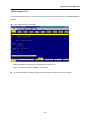
Press a function key ‘F3’ or touch ‘F3 Transfer’ button in the Main Menu of the main unit.
Transfer
!
"
#
!
Press ‘PC Main’ button
!
Enter the password.
!
$
%
(If a user can’t remember the password, enter a new password in the Initial Setup/System Setup mode.)
!
If there is no password, just press Enter button
!
Press ENTER key to be ready.
A-16
Appendix. Getting Started
!
Transfer the files from the Project Manager of the PMU-MASTER. to the Main Unit.
!
Press Start button.
!
The message “ Receiving…” appears during the downloading in the Main Unit.
!
‘Completed! <KEY>’ message is shown to the main unit after execution.
!
To interrupt transfer, press ESC key.
!
Before the communication, you should set the Initial Setup in the Main Menu.
!
Press Initial Setup key and select Serial Setup key.
!
Setup value is :
Baud rate : 19200bps
Data bits : 8bits
Stop bit : 1bit
Parity bit : odd
Interface : RS-422(4line)
Station number : 0
A-17
Appendix. Getting Started
&'
!
+
$#
$
(
!
!
%
"
!
.$
,
&'
&*(('
)
)
((*((
&'
-/
0
%
&(('
$
To select the left menu bar,
Select the menu directly by touching the menu bar
Press the menu bar to setup the data
!
To escape the current screen, press Cacel button.
!
Press Enter button.
A-18
*
(
-
Appendix. Getting Started
5. Edit a Program in PLC
To communicate with PMU and PLC, you should download a program to PLC using Programming Tool(LOGICMASTER 90
Software)
!
Create a Program for the communication.
M0001 : Bit address for Touch Tag and Lamp Tag( Buffer : 40, Bit number : 0)
R0001 : Word address for Numeric Tag(Buffer : 41. Word data)
!
For the detail information of editing a program in the programming tool, please refer to the User’s Manual.
A-19
Appendix. Getting Started
6. Cable Connection for serial Interface
9 pin
2
2
3
3
5
5
[Male]
PMU + Serial Option card
4 pin
15 pin
RDA
13
RDB
12
SDA
11
SDB
10
9 pin
[Female]
9
6
15
8
14
PMU
PLC[Male]
PLC[GE Fanuc(90-30) series] – Loader Port
A-20
PC