1
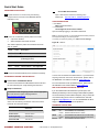
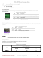
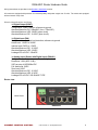
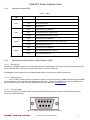
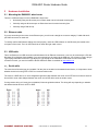
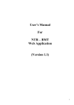
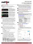
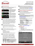
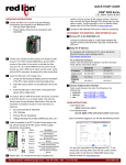
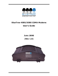
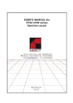
RAM-6021 Wired Router Quick Start Guide & Hardware Guide November 2013 Quick Start Guide UNPACKING INSTRUCTIONS Access Web User Interface 3 Open a web browser & enter the following in the address bar: http://192.168.0.1:10000/newgau.html 1 Unpack the Red Lion unit and verify the following components are enclosed for the RAM-6021 Router: RAM-6021 & CD LOGIN INSTRUCTIONS • User Name: admin (lowercase letters) • For Password: last six digits of the unit serial number Upon successfully logging in, the Web UI will launch. 2 There are 2 methods to provide power to the router: 4-pin screw terminal Side mounted 2.5mm barrel connector Note: For security purposes, it is recommended that the admin password be changed according to your internal policies. To change your password, please go to: Admin->Access Settings. Figure B - Web UI: The modem requires a power source between 8 and 30 VDC to operate: Label Color Description GND Black Ground PWR+ Red Power 8 to 30 VDC (500mA@12VDC) IN White Future feature – not supported OUT Green Future feature – not supported 3 Connect to the Ethernet RJ45 port for network connectivity. You are now connected to the Web interface. If you should see anything other than the screen shown above, please refer to the RAM-6021 User Manual located at: www.redlion.net. ACCESSSING THE WEB USER INTERFACE 1 Connect PC to the RAM-6021 Router Connect a CAT-5 Ethernet cable between the local PC and the unit’s Ethernet port. Verify that the green LED is lit. For more information to set up Modbus features, please refer to the RAM-6021 User Guide available at www.redlion.net. RED LION CONTROLS TECHNICAL SUPPORT 2 Setup PC IP Address For assistance with configuring your PC, see the appropriate Microsoft Windows support webpage listed at: http://support.microsoft.com. PC to Ethernet Interfaces Select “Use the following IP address” and fill in the blank fields with the information below: Ethernet 0 IP address 192.168.0.2 Subnet mask 255.255.255.0 Default gateway 192.168.0.1 Preferred DNS 192.168.0.1 CONNECT. MONITOR. CONTROL. If you have followed all of the instructions up to this point, have satisfied yourself that you are not having an authentication problem, are convinced that you have sufficient reception, and your unit is still not communicating, then it is time to contact Red Lion Technical Support at [email protected] or +1-877-432-9908 and we will be happy to assist you in getting your unit operational. HARDWARE STATUS LEDS LED State Description Power WAN ON ON FLASH ON FLASH ON Power is applied to the router Link established, but no data activity Data transmitted/received on network Link established with serial device but no data activity Data transmitted/received with attached serial device Link established with Ethernet device RS232 Ethernet © 2013 Sixnet, Inc. All Rights Reserved. 2 SOFTWARE LICENSING TERMS & CONDITIONS Software supplied with each Red Lion product remains the exclusive property of Red Lion Controls. Red Lion grants with each unit a perpetual license to use this software with the express limitation that the software may not be copied or used in any other product for any purpose. It may not be reverse engineered, or used for any other purpose other than in and with the computer hardware sold by Red Lion. WARRANTY Red Lion Controls provides a limited hardware warranty for the Industrial Pro Router, which consists of the following: This warranty is effective for three years from the delivery date of the IndustrialPro™ Router to the purchaser. The purchaser is responsible for returning the defective unit to our factory, freight prepaid. If the IndustrialPro™ Router is under warranty, Red Lion will repair it and return it, freight prepaid, via standard shipping. If the IndustrialPro™ Router is not covered by the warranty, we will notify you of the repair charges and not repair the IndustrialPro™ Router without your permission. Repairs are guaranteed for 90 days or the remainder of the warranty, whichever is longer. Buyer’s remedies for breach of warranty shall be limited to repair or replacement subject to adjustment as stated herein, or full or partial adjustment to purchase price. The Red Lion Industrial Pro Router is provided with the following warranty: Hardware maintenance and repair is available on a return to factory basis. After this initial period, configuration assistance will continue to be available on a chargeable basis. Software support does not provide for custom code. Custom changes are available as a chargeable option. The warranty only covers items with a serial number. Cables and adapters are not covered. For complete and most up-to-date warranty information go to www.redlion.net Notice: UL Listed as BT-6xxx model CONNECT. MONITOR. CONTROL. © 2013 Sixnet, Inc. All Rights Reserved. 3 RAM-6021 Router Hardware Guide TABLE OF CONTENTS Quick Start Guide................................................................................................................................................................ 2 UNPACKING INSTRUCTIONS ........................................................................................................................................ 2 1 Product Overview ................................................................................................................................................. 5 1.1 Specifications ............................................................................................................................................................. 5 1.1.1 1.1.2 1.1.3 1.1.4 1.1.5 1.1.6 General specifications ........................................................................................................................................5 Mechanical specifications RAM-6021 ................................................................................................................6 Power specifications and consumption ..............................................................................................................7 Indicators Lights (LED) ......................................................................................................................................9 Data Interface Specifications: Serial, Ethernet & USB ......................................................................................9 RESET button functions ...................................................................................................................................10 2 Hardware Installation ......................................................................................................................................... 11 2.1 Mounting the RAM-6021 wired router.................................................................................................................... 11 2.2 Ethernet cable ......................................................................................................................................................... 11 2.3 USB cable ................................................................................................................................................................. 11 2.4 Serial cable ............................................................................................................................................................ 11 2.5 Power source ........................................................................................................................................................... 12 Powering up the router ...................................................................................................................................................12 Testing the power connection ........................................................................................................................................12 CONNECT. MONITOR. CONTROL. © 2013 Sixnet, Inc. All Rights Reserved. 4 RAM-6021 Router Hardware Guide 1 Product Overview 1.1 Specifications 1.1.1 General specifications Table 1 – General specifications Serial interface 1x RS-232 Serial DB9 115200bps USB interface 1x USB 2.0 mini configuration port LED indicators Power, WAN, RS232, Ethernet Link & Activity Dimensions Weight Steel 120 x 96 x 51 mm (4.7” x 3.77” x 2.0”) 544 g (1.2 lbs) 4-pin screw terminal Power Input Side mounted 2.5 mm barrel connector 8-30 Vdc (nominal) Input current (max): 150mA Power consumption See Table 6 Operating Temp: -40 to +85°C (-40 to 185°F) Shock: IEC 60068-2-27 Environmental Vibration: IEC60068-2-6 Humidity: 5 to 95% non-condensing MTBF RAM-6021 1,832K Hours GB @ 40˚C per MIL-HNDBK-217F2 Hazardous Locations - Class I, Div. 2, Groups A,B,C,D, ANSI / ISA12.12.01 Certification Electrical Safety - UL508/CSA22.2/14 (CUL) EMC- FCC, part 15 and Industry Canada, ICES-003 CE, RoHS CONNECT. MONITOR. CONTROL. © 2013 Sixnet, Inc. All Rights Reserved. 5 RAM-6021 Router Hardware Guide 1.1.2 Mechanical specifications RAM-6021 CONNECT. MONITOR. CONTROL. © 2013 Sixnet, Inc. All Rights Reserved. 6 RAM-6021 Router Hardware Guide 1.1.3 Power specifications and consumption Power is supplied to the router via: 4-pin screw terminal Side mounted DC 2.5mm barrel connector router 4-pin Screw Terminal Power is supplied to the router via the 4-pin Screw Terminal on the front panel for the RAM-6021 router. The pins are described as follows: Table 4 - 4-pin screw terminal Pin Name Description Power connector (facing front) 1 GND 2 PWR+ 3 OUT 4 IN Ground Power supply input (8 to 30 VDC) (500mA@12VDC) Digital output Digital and analog input DC 2.5mm Barrel Connector Power is supplied to the router via the barrel connector on the left side of the RAM-6021 router. The contacts are described as follows: Pin Table 5 – DC 2.5mm Barrel adapter Name Description Sleeve GND Ground Tip PWR+ Power supply input (8 to 30 VDC) Power connector (facing left side) WARNING: DC 2.5mm Barrel Connector shall not be used in hazardous locations. Power specification Power input to the router is protected against reverse polarity and over-voltage. The router’s power consumption is as follows: Table 6 – Power consumption Draw in mA (at 12 VDC) Model RAM-6021 CONNECT. MONITOR. CONTROL. Standby Transmitting Peaks 115 360 531 © 2013 Sixnet, Inc. All Rights Reserved. 7 RAM-6021 Router Hardware Guide Wiring instructions are provided in the Hardware Installation section. All routers are equipped with protection for reversed polarity and power surges over 33 volts. The routers are equipped with an internal 3 Amp fuse. Electrical Specifications and Pinout 1x Digital Output (DOUT) Configuration: Open Collector, reference to ground Absolute Maximum IDC: 500mADC (Vce = 750mVDC) Absolute Maximum VDC: 30VDC (open circuit) Absolute Minimum VDC: -0.4VDC (open circuit) 1x Digital Input (DIN) Configuration: un-isolated level detection, reference to ground Active level: 1.6VDC to 30VDC Inactive level: 0VDC to 1.3VDC Absolute Minimum VDC: -0.3VDC Absolute Maximum VDC: 33VDC Leakage IDC at 5VDC: 150uADC 1x Analog Input (Shared with Digital Input) (DIN/AI1) Configuration: un-isolated input, reference to ground Resolution: 1024 (ADC 10-bit) VDC per step: 4.8875855mVDC Full scale level: 5VDC Zero level: 0VDC Absolute Minimum VDC: -0.3VDC Absolute Maximum VDC: 8.3VDC Leakage IDC at 5VDC: 265.96uADC TYPE Router view Wired Router RAM-6021 CONNECT. MONITOR. CONTROL. © 2013 Sixnet, Inc. All Rights Reserved. 8 RAM-6021 Router Hardware Guide 1.1.4 Indicators Lights (LED) Table 7 – LEDs LED Power Status Corresponding State OFF Router is powered off ON Router is powered on FLASH WAN RS232 OFF Connection is not established ON Link Established, but no data activity FLASH Data transmitted/received on network OFF Connection is not established ON Link established with serial device but no data activity *FLASH Ethernet Firmware error Data transmitted/received OFF Connection is not established ON Link established with Ethernet device FLASH Data transmitted/received *Depending on Serial Application 1.1.5 Data Interface Specifications: Serial, Ethernet & USB 1.1.5.1 Ethernet Port The router's 10/100Mbps Ethernet port is compliant with the EIA-568 standard. The router’s ports are autosensing so they can be used with either a straight or crossover RJ45 cable to connect to host ports. The RAM-6021 Router features a 5-port Ethernet switch allowing connectivity to multiple local devices. 1.1.5.2 USB Device Port This is a USB 2.0 Device interface on a Mini B connector. It offers Ethernet-over-USB functionality using the RNDIS driver for Windows XP and Windows Vista Operating systems only. The BlueTree RNDIS driver must be installed before the USB interface can be used. The driver and instructions can be obtained at www.redlion.net. 1.1.5.3 Serial Port (DB9) The router’s serial port is an RS232 DCE, compliant with EIA-232 standard. The connector used is DB9 female and is shown in the illustration below. Figure 1 – Serial connector (looking at front of router) CONNECT. MONITOR. CONTROL. © 2013 Sixnet, Inc. All Rights Reserved. 9 RAM-6021 Router Hardware Guide For further serial wiring information, refer to the Hardware Installation section. 1.1.6 RESET button functions Table 8 – Reset button functions Mode Pattern Description Hard reset Press and hold for less than 3 seconds Standard reboot Factory restore Press and hold between 3 and 10 seconds RS232 LED flashes quickly To restore default settings for older versions, rerun the SN Reflashing procedure found at www.redlion.net FW upgrade Press and hold between 10 and 15 seconds WAN LED flashes quickly Puts the router in advanced firmware upgrade mode by restarting the router and running the boot loader only. Do not use this mode unless instructed to by Red Lion Technical Support. USB pass-through Press and hold for longer than 15 seconds Signal LED flashes quickly Puts the router in main pass-through mode to the RF module, allowing CCT provisioning and PST support. Do not use this mode unless instructed to by Red Lion Technical Support. CONNECT. MONITOR. CONTROL. © 2013 Sixnet, Inc. All Rights Reserved. 10 RAM-6021 Router Hardware Guide 2 Hardware Installation 2.1 Mounting the RAM-6021 wired router There are 3 different ways to mount a RAM-6021 wired router: Horizontally using two #6 screws pan or fillister head onto its horizontal mounting feet Vertically using two #6 screws pan or fillister head onto its vertical mounting feet Vertically using a DIN rail clip 2.2 Ethernet cable If you are connecting to the router via the Ethernet port, you will need a straight or crossover category 5 cable with two 8pin RJ45 connectors on each end. To visually confirm that Ethernet cabling was done properly, check the LED indication on the Ethernet port located at the rear panel of the router. The Link LED should be on when the right cable is used. 2.3 USB cable This is an Ethernet-over-USB connection which behaves like an Ethernet connection. It can only be connected to a PC with Windows XP or Windows Vista installed. If you are connecting to the router via the USB port, you will need a Type A plug to Type B plug USB cable for the mini Type B plug to Type A plug for the RAM-6021 wired router In order for the USB connection to work, you need to install the Sixnet USB driver which is available at www.redlion.net. 2.4 Serial cable The router has all its serial port pins enabled. If all the pins are enabled on the attached serial device, it is important to know whether the device is using DTE or DCE as a communication mode. The router is a DCE device, so use a straight-through serial cable between the router and a DTE device such as a terminal. Use a NULL router cable adapter between the router and a DCE device such as another router. If using custom wiring or if some pins are disabled, follow the guidelines below. The wiring will vary depending on whether the attached serial device is a DTE or DCE. CONNECT. MONITOR. CONTROL. © 2013 Sixnet, Inc. All Rights Reserved. 11 RAM-6021 Router Hardware Guide 2.5 Power source IMPORTANT Any installations involving electrical wiring and connections should be done by someone who is experienced in this field. As described in the Power specifications and consumption section, the router can be powered using: 4-pin screw terminal Side mounted 2.5mm barrel connector WARNING DC 2.5mm Barrel Connector shall not be used in hazardous locations. Powering up the router The router will power up as soon as an 8 to 30 VDC voltage is applied to one of its power inputs and shuts off when this input voltage is below 4 VDC. Testing the power connection Check the PWR light on the router: if it is turned on then the router is powered. If it’s off, then review the installation procedures, or contact Red Lion Technical Support for further assistance. CONNECT. MONITOR. CONTROL. © 2013 Sixnet, Inc. All Rights Reserved. 12