1
USER'S MANUAL
Fuji Electric FA Components & Systems Co., Ltd.
Mitsui Sumitomo Bank Ningyo-cho Bldg.,
5-7, Nihonbashi Odemma-cho, Chuo-ku, Tokyo 103-0011, Japan
Phone: +81-3-5847-8011 Fax: +81-3-5847-8172
Information in this manual is subject to change without notice.
Printed in Japan 2006-3 (C06/C06) CM 10 FIS
MEH457
FRENIC Multi ユーザーズマニュアル_EC■M■Y■K■
High Performance Compact Inverter
User's Manual
Copyright © 2006 Fuji Electric FA Components & Systems Co., Ltd.
All rights reserved.
No part of this publication may be reproduced or copied without prior written permission from Fuji Electric
FA Components & Systems Co., Ltd.
All products and company names mentioned in this manual are trademarks or registered trademarks of their
respective holders.
The information contained herein is subject to change without prior notice for improvement.
Preface
This manual provides all the information on the FRENIC-Multi series of inverters including its operating
procedure, operation modes, and selection of peripheral equipment. Carefully read this manual for proper use.
Incorrect handling of the inverter may prevent the inverter and/or related equipment from operating correctly,
shorten their lives, or cause problems.
The table below lists the other materials related to the use of the FRENIC-Multi. Read them in conjunction
with this manual as necessary.
Name
Catalog
Instruction Manual
Material No.
Description
MEH652
Product scope, features, specifications,
drawings, and options of the product
INR-SI47-1094-E
Acceptance inspection, mounting & wiring of the
inverter, operation using the keypad, running the motor
for a test, troubleshooting, and maintenance and
inspection
The materials are subject to change without notice. Be sure to obtain the latest editions for use.
i
external
Japanese Guideline for Suppressing Harmonics by Customers Receiving
High Voltage or Special High Voltage
Refer to this manual, Appendix B for details on this guideline.
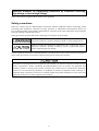
Safety precautions
Read this manual and the FRENIC-Multi Instruction Manual (INR-SI47-1094-E) thoroughly before
proceeding with installation, connections (wiring), operation, or maintenance and inspection. Ensure you
have sound knowledge of the product and familiarize yourself with all safety information and precautions
before proceeding to operate the inverter.
Safety precautions are classified into the following two categories in this manual.
Failure to heed the information indicated by this symbol may lead to
dangerous conditions, possibly resulting in death or serious bodily injuries.
Failure to heed the information indicated by this symbol may lead to
dangerous conditions, possibly resulting in minor or light bodily injuries
and/or substantial property damage.
Failure to heed the information contained under the CAUTION title can also result in serious consequences.
These safety precautions are of utmost importance and must be observed at all times.
This product is not designed for use in appliances and machinery on which lives depend. Consult your Fuji
Electric representative before considering the FRENIC-Multi series of inverters for equipment and
machinery related to nuclear power control, aerospace uses, medical uses or transportation. When the
product is to be used with any machinery or equipment on which lives depend or with machinery or
equipment which could cause serious loss or damage should this product malfunction or fail, ensure that
appropriate safety devices and/or equipment are installed.
ii
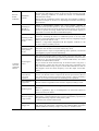
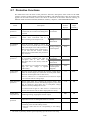
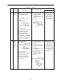
Precautions for Use
Driving a 400 V
general-purpose
motor
When driving a 400 V general-purpose motor with an inverter using
extremely long wires, damage to the insulation of the motor may occur. Use
an output circuit filter (OFL) if necessary after checking with the motor
manufacturer. Fuji motors do not require the use of output circuit filters
because of their reinforced insulation.
Torque
characteristics and
temperature rise
When the inverter is used to run a general-purpose motor, the temperature
of the motor becomes higher than when it is operated using a commercial
power supply. In the low-speed range, the cooling effect will be weakened,
so decrease the output torque of the motor. If constant torque is required in
the low-speed range, use a Fuji inverter motor or a motor equipped with an
externally powered ventilating fan.
In running
generalpurpose
motors
When an inverter-driven motor is mounted to a machine, resonance may be
caused by the natural frequencies of the machine system.
Vibration
Note that operation of a 2-pole motor at 60 Hz or higher may cause
abnormal vibration.
* The use of a rubber coupling or vibration-proof rubber is recommended.
* Use the inverter's jump frequency control feature to skip the resonance
frequency zone(s).
Noise
When an inverter is used with a general-purpose motor, the motor noise
level is higher than that with a commercial power supply. To reduce noise,
raise carrier frequency of the inverter. Operation at 60 Hz or higher can also
result in higher level of wind roaring sound.
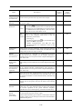
High-speed
motors
If the reference frequency is set to 120 Hz or more to drive a high-speed
motor, test-run the combination of the inverter and motor beforehand to
check for safe operation.
Explosion-proof
motors
When driving an explosion-proof motor with an inverter, use a combination
of a motor and an inverter that has been approved in advance.
Submersible
motors and pumps
These motors have a higher rated current than general-purpose motors.
Select an inverter whose rated output current is higher than that of the
motor.
These motors differ from general-purpose motors in thermal characteristics.
Set a low value in the thermal time constant of the motor when setting the
electronic thermal overcurrent protection (for motor).
Brake motors
For motors equipped with parallel-connected brakes, their power supply for
brake must be supplied from the inverter’s primary circuit. If the power
supply for brake is connected to the inverter's output circuit by mistake, the
brake will not work.
Do not use inverters for driving motors with series-connected brake coils.
Geared motors
If the power transmission mechanism uses an oil-lubricated gearbox or
speed changer/reducer, then continuous motor operation at low speed may
cause poor lubrication. Avoid such operation.
Synchronous
motors
It is necessary to take special measures suitable for this motor type. Contact
your Fuji Electric representative for details.
Single-phase
motors
Single-phase motors are not suitable for inverter-driven variable speed
operation. Use three-phase motors.
In running
special
motors
iii
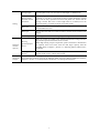
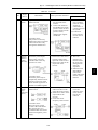
Environmental
conditions
Combination with
peripheral
devices
Installation
location
Use the inverter within the ambient temperature range from -10 to +50°C.
The heat sink and braking resistor of the inverter may become hot under
certain operating conditions, so install the inverter on nonflammable
material such as metal.
Ensure that the installation location meets the environmental conditions
specified in Chapter 8, Section 8.4 "Operating Environment and Storage
Environment."
Installing an
MCCB or
RCD/ELCB
Install a recommended molded case circuit breaker (MCCB) or
residual-current-operated protective device (RCD)/earth leakage circuit
breaker (ELCB) (with overcurrent protection) in the primary circuit of each
inverter to protect the wiring. Ensure that the circuit breaker capacity is
equivalent to or lower than the recommended capacity.
Installing an MC
in the secondary
circuit
If a magnetic contactor (MC) is installed in the inverter's output (secondary)
circuit for switching the motor to commercial power or for any other
purpose, ensure that both the inverter and the motor are completely stopped
before you turn the MC on or off.
Remove a surge killer integrated with the magnetic contactor in the
inverter's output (secondary) circuit.
Installing an MC
in the primary
circuit
Do not turn the magnetic contactor (MC) in the primary circuit on or off
more than once an hour as an inverter failure may result.
If frequent starts or stops are required during motor operation, use terminal
[FWD]/[REV] signals or the RUN/STOP key.
Protecting the
motor
The electronic thermal feature of the inverter can protect the motor. The
operation level and the motor type (general-purpose motor, inverter motor)
should be set. For high-speed motors or water-cooled motors, set a small
value for the thermal time constant.
If you connect the motor thermal relay to the motor with a long wire, a
high-frequency current may flow into the wiring stray capacitance. This
may cause the thermal relay to trip at a current lower than the set value. If
this happens, lower the carrier frequency or use the output circuit filter
(OFL).
Discontinuance of
power-factor
correcting
capacitor
Do not connect power-factor correcting capacitors to the inverter’s primary
circuit. (Use the DC reactor to improve the inverter power factor.) Do not
use power-factor correcting capacitors in the inverter’s output (secondary)
circuit. An overcurrent trip will occur, disabling motor operation.
Discontinuance of
surge killer
Do not connect a surge killer to the inverter's output (secondary) circuit.
Reducing noise
Use of a filter and shielded wires is typically recommended to satisfy EMC
Directive.
Refer to Appendices, App. A "Advantageous Use of Inverters (Notes on
electrical noise)" for details.
Measures against
surge currents
If an overvoltage trip occurs while the inverter is stopped or operated under
light load, it is assumed that the surge current is generated by open/close of
the phase-advancing capacitor in the power system.
* Connect a DC reactor to the inverter.
Megger test
When checking the insulation resistance of the inverter, use a 500 V megger
and follow the instructions contained in the FRENIC-Multi Instruction
Manual (INR-SI47-1094-E), Chapter 7, Section 7.5 "Insulation Test."
iv
Control circuit
wiring length
When using remote control, limit the wiring length between the inverter and
operator panel to 20 m or less and use twisted pair or shielded wire.
Wiring length
between inverter
and motor
If long wiring is used between the inverter and the motor, the inverter may
overheat or trip due to overcurrent because a higher harmonics current
flows into the stray capacitance between each phase wire. Ensure that the
wiring is shorter than 50 m. If this length must be exceeded, lower the
carrier frequency or install an output circuit filter (OFL).
Wire size
Select wires with a sufficient capacity by referring to the current value or
recommended wire size.
Wire type
Do not share one multi-core cable in order to connect several inverters with
motors.
Grounding
Securely ground the inverter using the grounding terminal.
Driving
general-purpose
motor
Select an inverter according to the nominal applied motor ratings listed in
the standard specifications table for the inverter.
When high starting torque is required or quick acceleration or deceleration
is required, select an inverter with one rank larger capacity than the
standard. Refer to Chapter 7, Section 7.1 "Selecting Motors and Inverters"
for details.
Driving special
motors
Select an inverter that meets the following condition:
Inverter rated current > Motor rated current
Wiring
Selecting
inverter
capacity
Transportation and
storage
When transporting or storing inverters, follow the procedures and select locations that meet the
environmental conditions listed in the FRENIC-Multi Instruction Manual (INR-SI47-1094-E),
Chapter 1, Section 1.3 "Transportation" and Section 1.4 "Storage Environment."
v
How this manual is organized
This manual contains Chapters 1 through 9, Appendices and Glossary.
Part 1 General Information
Chapter 1 INTRODUCTION TO FRENIC-Multi
This chapter describes the features and control system of the FRENIC-Multi series, and the recommended
configuration for the inverter and peripheral equipment.
Chapter 2 PARTS NAMES AND FUNCTIONS
This chapter contains external views of the FRENIC-Multi series and an overview of terminal blocks,
including a description of the LED display and keys on the keypad.
Chapter 3 OPERATION USING THE KEYPAD
This chapter describes inverter operation using the keypad. The inverter features three operation modes
(Running, Programming and Alarm modes) which enable you to run and stop the motor, monitor running
status, set function code data, display running information required for maintenance, and display alarm data.
Part 2 Driving the Motor
Chapter 4 BLOCK DIAGRAMS FOR CONTROL LOGIC
This chapter describes the main block diagrams for the control logic of the FRENIC-Multi series of inverters.
Chapter 5 RUNNING THROUGH RS-485 COMMUNICATION
This chapter describes an overview of inverter operation through the RS-485 communications facility. Refer
to the RS-485 Communication User's Manual (MEH448b) or RS-485 Communications Card "OPC-E1-RS"
Installation Manual (INR-SI47-1089) for details.
Part 3 Peripheral Equipment and Options
Chapter 6 SELECTING PERIPHERAL EQUIPMENT
This chapter describes how to use a range of peripheral equipment and options, FRENIC-Multi's
configuration with them, and requirements and precautions for selecting wires and crimp terminals.
Part 4 Selecting Optimal Inverter Model
Chapter 7 SELECTING OPTIMAL MOTOR AND INVERTER CAPACITIES
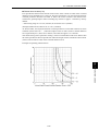
This chapter provides you with information about the inverter output torque characteristics, selection
procedure, and equations for calculating capacities to help you select optimal motor and inverter models. It
also helps you select braking resistors.
vi
Part 5 Specifications
Chapter 8 SPECIFICATIONS
This chapter describes specifications of the output ratings, control system, and terminal functions for the
FRENIC-Multi series of inverters. It also provides descriptions of the operating and storage environment,
external dimensions, examples of basic connection diagrams, and details of the protective functions.
Chapter 9 FUNCTION CODES
This chapter contains overview lists of seven groups of function codes available for the FRENIC-Multi series
of inverters and details of each function code.
Appendices
Glossary
Icons
The following icons are used throughout this manual.
This icon indicates information which, if not heeded, can result in the inverter not operating to
full efficiency, as well as information concerning incorrect operations and settings which can
result in accidents.
This icon indicates information that can prove handy when performing certain settings or
operations.
This icon indicates a reference to more detailed information.
vii
CONTENTS
Part 1 General Information
Chapter 1 INTRODUCTION TO FRENIC-Multi
1.1
Features..................................................................................................................................................... 1-1
1.2
Control System ....................................................................................................................................... 1-11
1.3
Recommended Configuration ................................................................................................................. 1-13
Chapter 2 PARTS NAMES AND FUNCTIONS
2.1
External View and Allocation of Terminal Blocks.................................................................................... 2-1
2.2
LED Monitor, Keys and LED Indicators on the Keypad .......................................................................... 2-2
Chapter 3 OPERATION USING THE KEYPAD
3.1
Overview of Operation Modes ................................................................................................................. 3-1
3.2
Running Mode .......................................................................................................................................... 3-3
3.2.1 Monitoring the running status ............................................................................................................. 3-3
3.2.2 Setting up frequency and PID commands ........................................................................................... 3-4
3.2.3 Running/stopping the motor................................................................................................................ 3-9
3.2.4 Jogging Operation ............................................................................................................................... 3-9
3.3
Programming Mode ................................................................................................................................ 3-10
3.3.1 Setting up basic function codes quickly -- Menu #0 "Quick Setup" --.............................................. 3-12
3.3.2 Setting up function codes -- Menu #1 "Data Setting" --................................................................... 3-16
3.3.3 Checking changed function codes -- Menu #2 "Data Checking" -- .................................................. 3-17
3.3.4 Monitoring the running status -- Menu #3 "Drive Monitoring" -- ................................................... 3-18
3.3.5 Checking I/O signal status -- Menu #4 "I/O Checking" -- ............................................................... 3-21
3.3.6 Reading maintenance information -- Menu #5 "Maintenance Information" -- ................................ 3-26
3.3.7 Reading alarm information -- Menu #6 "Alarm Information" --...................................................... 3-29
3.4
Alarm Mode............................................................................................................................................ 3-32
3.4.1 Releasing the alarm and switching to Running mode ....................................................................... 3-32
3.4.2 Displaying the alarm history ............................................................................................................. 3-32
3.4.3 Displaying the status of inverter at the time of alarm ....................................................................... 3-32
3.4.4 Switching to Programming mode...................................................................................................... 3-32
Part 2 Driving the Motor
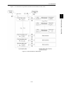
Chapter 4 BLOCK DIAGRAMS FOR CONTROL LOGIC
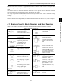
4.1
Symbols Used in Block Diagrams and their Meanings ............................................................................ 4-1
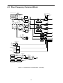
4.2
Drive Frequency Command Block ........................................................................................................... 4-2
4.3
Drive Command Block ............................................................................................................................. 4-6
4.4
Control Block............................................................................................................................................ 4-8
4.5
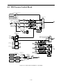
PID Process Control Block ..................................................................................................................... 4-12
4.6
PID Dancer Control Block...................................................................................................................... 4-16
4.7
FM Output Selector ................................................................................................................................ 4-19
viii
Chapter 5 RUNNING THROUGH RS-485 COMMUNICATION
5.1
Overview on RS-485 Communication...................................................................................................... 5-1
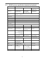
5.1.1 RS-485 common specifications (standard and optional)..................................................................... 5-2
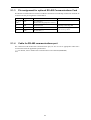
5.1.2 RJ-45 connector pin assignment for standard RS-485 communications port...................................... 5-3
5.1.3 Pin assignment for optional RS-485 Communications Card............................................................... 5-4
5.1.4 Cable for RS-485 communications port.............................................................................................. 5-4
5.1.5 Communications support devices........................................................................................................ 5-5
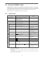
5.2
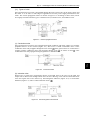
Overview of FRENIC Loader................................................................................................................... 5-6
5.2.1 Specifications ...................................................................................................................................... 5-6
5.2.2 Connection .......................................................................................................................................... 5-7
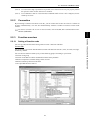
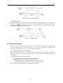
5.2.3 Function overview............................................................................................................................... 5-7
5.2.3.1 Setting of function code .............................................................................................................. 5-7
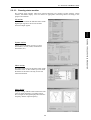
5.2.3.2 Multi-monitor.............................................................................................................................. 5-8
5.2.3.3 Running status monitor ............................................................................................................... 5-9
5.2.3.4 Test-running .............................................................................................................................. 5-10
5.2.3.5 Real-time trace—Displaying running status of an inverter in waveforms ................................ 5-11
Part 3 Peripheral Equipment and Options
Chapter 6 SELECTING PERIPHERAL EQUIPMENT
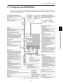
6.1
Configuring the FRENIC-Multi................................................................................................................ 6-1
6.2
Selecting Wires and Crimp Terminals....................................................................................................... 6-2
6.2.1 Recommended wires ........................................................................................................................... 6-4
6.3
Peripheral Equipment ............................................................................................................................... 6-8
6.4
Selecting Options.................................................................................................................................... 6-14
6.4.1 Peripheral equipment options............................................................................................................ 6-14
6.4.2 Options for operation and communications ...................................................................................... 6-23
6.4.3 Meter options .................................................................................................................................... 6-26
Part 4 Selecting Optimal Inverter Model
Chapter 7 SELECTING OPTIMAL MOTOR AND INVERTER CAPACITIES
7.1
Selecting Motors and Inverters ................................................................................................................. 7-1
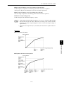
7.1.1 Motor output torque characteristics..................................................................................................... 7-1
7.1.2 Selection procedure............................................................................................................................. 7-4
7.1.3 Equations for selections ...................................................................................................................... 7-7
7.1.3.1 Load torque during constant speed running ................................................................................ 7-7
7.1.3.2 Acceleration and deceleration time calculation........................................................................... 7-8
7.1.3.3 Heat energy calculation of braking resistor............................................................................... 7-11
7.1.3.4 Calculating the RMS rating of the motor .................................................................................. 7-12
7.2
Selecting a Braking Resistor................................................................................................................... 7-13
7.2.1 Selection procedure........................................................................................................................... 7-13
7.2.2 Notes on selection ............................................................................................................................. 7-13
ix
Part 5 Specifications
Chapter 8 SPECIFICATIONS
8.1
Standard Models ....................................................................................................................................... 8-1
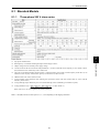
8.1.1 Three-phase 200 V class series ........................................................................................................... 8-1
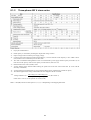
8.1.2 Three-phase 400 V class series ........................................................................................................... 8-2
8.1.3 Single-phase 200 V class series........................................................................................................... 8-3
8.2
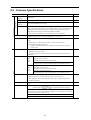
Common Specifications............................................................................................................................ 8-4
8.3
Terminal Specifications ............................................................................................................................ 8-8
8.3.1 Terminal functions .............................................................................................................................. 8-8
8.3.2 Terminal arrangement diagram and screw specifications.................................................................. 8-19
8.3.2.1 Main circuit terminals ............................................................................................................... 8-19
8.3.2.2 Control circuit terminals............................................................................................................ 8-20
8.4
Operating Environment and Storage Environment ................................................................................. 8-21
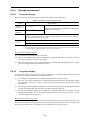
8.4.1 Operating environment...................................................................................................................... 8-21
8.4.2 Storage environment ......................................................................................................................... 8-22
8.4.2.1 Temporary storage..................................................................................................................... 8-22
8.4.2.2 Long-term storage ..................................................................................................................... 8-22
8.5
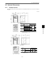
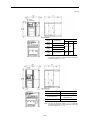
External Dimensions............................................................................................................................... 8-23
8.5.1 Standard models ................................................................................................................................ 8-23
8.5.2 Standard keypad ................................................................................................................................ 8-26
8.6
Connection Diagrams ............................................................................................................................. 8-27
8.6.1 Running the inverter with keypad ..................................................................................................... 8-27
8.6.2 Running the inverter by terminal commands .................................................................................... 8-28
8.7
Protective Functions ............................................................................................................................... 8-30
Chapter 9 FUNCTION CODES
9.1
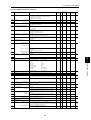
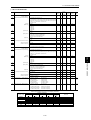
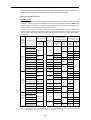
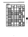
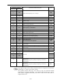
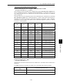
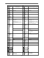
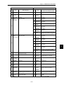
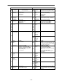
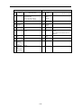
Function Code Tables ............................................................................................................................... 9-1
9.2
Overview of Function Codes .................................................................................................................. 9-14
9.2.1 F codes (Fundamental functions) ...................................................................................................... 9-14
9.2.2 E codes (Extension terminal functions)............................................................................................. 9-43
9.2.3 C codes (Control functions) .............................................................................................................. 9-70
9.2.4 P codes (Motor 1 parameters) ........................................................................................................... 9-77
9.2.5 H codes (High performance functions) ............................................................................................. 9-80
9.2.6 A codes (Motor 2 parameters)......................................................................................................... 9-102
9.2.7 J codes (Application functions)....................................................................................................... 9-104
9.2.8 y codes (Link functions).................................................................................................................. 9-119
x
Appendices
App.A
A.1
A.2
A.3
App.B
B.1
B.2
App.C
C.1
C.2
C.3
C.4
App.D
App.E
App.F
App.G
G.1
G.2
G.3
Advantageous Use of Inverters (Notes on electrical noise)................................................................... A-1
Effect of inverters on other devices ....................................................................................................... A-1
Noise...................................................................................................................................................... A-2
Noise prevention.................................................................................................................................... A-4
Japanese Guideline for Suppressing Harmonics by Customers Receiving High Voltage
or Special High Voltage ....................................................................................................................... A-12
Application to general-purpose inverters............................................................................................. A-12
Compliance to the harmonic suppression for customers receiving high voltage or
special high voltage ............................................................................................................................. A-13
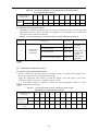
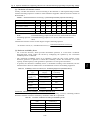
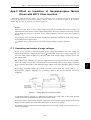
Effect on Insulation of General-purpose Motors Driven with 400 V Class Inverters.......................... A-17
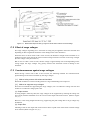
Generating mechanism of surge voltages ............................................................................................ A-17
Effect of surge voltages ....................................................................................................................... A-18
Countermeasures against surge voltages ............................................................................................. A-18
Regarding existing equipment ............................................................................................................. A-19
Inverter Generating Loss ..................................................................................................................... A-20
Conversion from SI Units.................................................................................................................... A-21
Allowable Current of Insulated Wires ................................................................................................. A-23
Replacement Information .................................................................................................................... A-25
External dimensions comparison tables............................................................................................... A-25
Terminal arrangements and symbols ................................................................................................... A-28
Function codes..................................................................................................................................... A-31
Glossary
xi
Part 1 General Information
Chapter 1 INTRODUCTION TO FRENIC-Multi
Chapter 2 PARTS NAMES AND FUNCTIONS
Chapter 3 OPERATION USING THE KEYPAD
Chapter 1
INTRODUCTION TO FRENIC-Multi
This chapter describes the features and control system of the FRENIC-Multi series and the recommended
configuration for the inverter and peripheral equipment.
Contents
1.1
1.2
1.3
Features....................................................................................................................................................... 1-1
Control System.......................................................................................................................................... 1-11
Recommended Configuration ................................................................................................................... 1-13
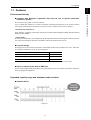
1.1 Features
Chap. 1
1.1 Features
Complies with European regulations that limit the use of specific hazardous
substances (RoHS)
These inverters are gentle on the environment.
Use of 6 hazardous substances is limited. (Products manufactured beginning in the autumn of 2005
will comply with European regulations (except for interior soldering in the power module.))
<Six Hazardous Substances>
Lead, Mercury, Cadmium, Hexavalent Chromium, Polybrominated biphenyl (PBB), Polybrominated
diphenyl ether (PBDE)
<About RoHS>
The Directive 2002/95/EC, promulgated by the European Parliament and European Council, limits the
use of specific hazardous substances included in electrical and electronic devices.
Long-life design
The design life of each internal component with limited life has been extended to 10 years. This helps
to extend the maintenance cycle for your equipment.
Limited Life Component
Service Life
Main circuit capacitors
10 years
Electrolytic capacitors on printed circuit boards
10 years
Cooling fan
10 years
Conditions: Ambient temperature is 40°C and load factor is 80% of the inverter's rated current.
Noise is reduced by the built-in EMC filter
Use of a built-in EMC filter that reduces noise generated by the inverter makes it possible to reduce the
effect on peripheral equipment.
Expanded capacity range and abundant model variation
Standard Series
Figure 1.1
1-1
INTRODUCTION TO FRENIC-Multi
Environment-friendly
Semi-standard Series (Available soon)
- Models with built-in EMC filter
- Models with built-in PG interface card
- Models with built-in RS-485 communications card
- Models for synchronous motors
Figure 1.2
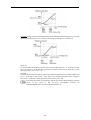
The highest standards of control and performance in its class
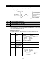
Shortened setting time in slip compensation control
Through "slip compensation control" + "voltage tuning," speed control accuracy at low speeds is
improved. This minimizes variations in speed control accuracy at times when the load varies, and
since the time at creep speeds is shortened, single cycle tact times can be shortened.
Figure 1.3
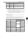
Equipped with the highest level CPU for its class
The highest level CPU of any inverter is used. Computation and processing capacity is doubled over
the previous inverter, improving speed control accuracy.
CPU speed comparison
Figure 1.4
Compatible with PG feedback control
Figure 1.5
1-2
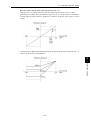
1.1 Features
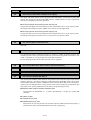
The inverter controls the energy level generated and the deceleration time, and so deceleration stop
can be accomplished without tripping due to overvoltage.
Chap. 1
Tripless deceleration by automatic deceleration control
INTRODUCTION TO FRENIC-Multi
Figure 1.6
Optimum for the operations specific to vertical and horizontal conveyance
Hit-and-stop control is realized more easily
Impacts are detected mechanically and not only can the inverter's operation pattern be set on
coast-to-stop or deceleration stop, but switching from torque limitation to current limitation and
generating a holding torque (hit-and-stop control) can be selected, making it easy to adjust brake
application and release timing.
Figure 1.7
Inclusion of a brake signal makes it even more convenient
At brake release time
After the motor operates, torque generation is detected and signals are output.
At brake application time
Brake application that matches the timing can be done, and so mechanical brake wear is reduced.
1-3
Limit operations can be selected to match your equipment
Inverters are equipped with two limit operations, "torque limitation" and "current limitation," so either
can be selected to match the equipment you are using the inverter with.
Torque limitation
In order to protect mechanical systems, this function accurately limits the torque generated by the
motor. (Instantaneous torque cannot be limited.)
Current limitation
This function limits the current flowing to the motor to protect the motor thermally or to provide rough
load limitation. (Instantaneous current cannot be limited. Auto tuning is not required.)
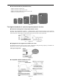
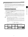
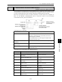
Simple and thorough maintenance
The life information on each of the inverter's limited life components is displayed
Figure 1.8
Simple cooling fan replacement
Construction is simple, enabling quick removal of the top cover and making it easy to replace the
cooling fan. (5.5 kW or higher models)
Cooling fan replacement procedure
The cover on top of the
inverter can be quickly
removed.
Simply disconnect the
power connector and
replace the cooling fan.
Figure 1.9
Information that contributes to equipment maintenance is displayed
In addition to inverter maintenance information, data that also take equipment maintenance into
consideration are displayed.
Item
Purpose
Motor cumulative
running time (hr)
The actual cumulative running time of the equipment (motor) the inverter is being
used with is calculated.
<Example of use>
If the inverter is used to control a fan, this information is an indication of the timing
for replacing the belt that is used on the pulleys.
Number of starts
(times)
The number of times the inverter starts and stops can be counted.
<Example of use>
The number of equipment starts and stops is recorded, and so this information can
be used as a guideline for parts replacement timing in equipment in which starting
and stopping puts a heavy load on the machinery.
1-4
1.1 Features
Detailed information can be checked for the four most recent alarms.
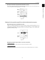
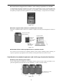
A removable keypad is standard equipment
The keypad can be easily removed and reset, making remote operation possible. If the back cover
packed with the inverter is installed and a LAN cable is used, the keypad can be easily mounted on the
equipment's control panel.
Figure 1.10
A removable interface board is used
The interface board is used as a terminal block for control signals. Since it is removable, wiring
operations are simple.
Figure 1.11
All types and variations of interface board are available as options (available soon). Optional interface
boards have the same dimensions as the standard interface board supplied with the inverter, so it is
possible to meet optional specifications using the same installation space as with standard
specification models.
1-5
INTRODUCTION TO FRENIC-Multi
Simple operation, simple wiring
Chap. 1
The alarm history records the latest four incidents
A multi-function keypad which enables a wide variety of operations is available
A multi-function keypad is available as an option. This keypad features a large 7-segment LED with
five digits and large backlit liquid crystal panel. Its view-ability is high, and guidance is displayed on
the liquid crystal panel, therefore operations can be conducted simply. (A copy function is included.)
Figure 1.12
Inverter support loader software is available (On sale soon)
Windows compatible loader software is available to simplify the setting and management of function
codes.
RS-485 communication
(RJ-45 connector)
Personal computer
USB/RS-485
converter
(made by System
Sacom Sales
Corp.)
USB cable
(that comes with
the converter)
Figure 1.13
Simulated failure enables peripheral device operation checks
The inverter has the function for outputting dummy alarm signals, enabling simple checking of
sequence operations of peripheral devices from the control panel where the inverter is used.
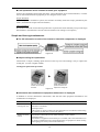
Consideration of peripheral equipment, and a full range of protective functions
Side-by-side mounting saves space
If your control panel is designed to use multiple inverters, these inverters make it possible to save
space through their horizontal side-by-side installation. (3.7 kW or smaller models)
(The 3-phase 200 V, 0.75 kW
model is shown here.)
Figure 1.14
1-6
1.1 Features
Outside panel cooling is also made possible using
the mounting adapter for external cooling (option). The mounting adapter for external cooling (option)
can be installed easily as an outside panel cooling system. This function is standard on 5.5 kW or
higher models.
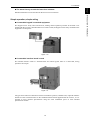
You can use an inverter equipped with functions like these
New system for more energy-efficient operation
Previous energy saving operation functions worked only to control the motor's loss to keep it at a
minimum in accordance with the load condition. In the newly developed FRENIC-Multi Series, the
focus has been switched away from the motor alone to both the motor and the inverter as electrical
products. As a result, we incorporated a new control system (optimum and minimum power control)
that minimizes the power consumed by the inverter itself (inverter loss) and the loss of the motor.
Figure 1.15
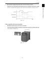
Smooth starts through the auto search
In the case where a fan is not being run by the inverter but is turning free, the fan's speed is checked,
regardless of its rotational direction, and operation of the fan is picked up to start the fan smoothly.
This function is convenient in such cases as when switching instantaneously from commercial power
supply to the inverter.
Figure 1.16
1-7
INTRODUCTION TO FRENIC-Multi
When FRENIC-Multi Series (including FRENIC-Mini Series, FRENIC-Eco Series and 11 Series) is
used, the built-in resistor suppresses the inrush current generated when the motor starts. Therefore, it is
possible to select peripheral equipment with lower capacity when designing your system than the
equipment needed for direct connection to the motor.
Chap. 1
Resistors for suppressing inrush current are built in, making it possible to reduce
the capacity of peripheral equipment
Equipped with a full range of PID control functions
Differential alarm and absolute value alarm outputs have been added for PID regulator which carry out
process controls such as temperature, pressure and flowrate control. In addition, an anti-reset windup
function to prevent PID control overshoot and other PID control functions which can be adjusted
easily through PID output limiter, integral hold/reset signals are provided. The PID output limiter and
integral hold/reset signals can also be used in cases where the inverter is used for dancer control.
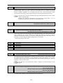
Operating signal trouble is avoided by the command loss detection function
If frequency signals connected to the inverter (0 to 10 V, 4 to 20 mA, Multi-speed signals,
communications, etc.) are interrupted, the missing frequency commands are detected as a "command
loss." Further, the frequency that is output when command loss occurs can be set in advance, so
operation can be continued even in cases where the frequency signal lines are cut due to mechanical
vibrations of the equipment, etc.
Figure 1.17
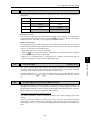
An overload stop function protects equipment from over-operation
If the load on equipment suddenly becomes great while controlled by the inverter, the inverter can be
switched to deceleration stop or to coast-to-stop operation to prevent damage to the equipment.
Figure 1.18
1-8
1.1 Features
Figure 1.19
Fully compatible with network operation
RS-485 communications (connector) is standard
A connector (RJ-45) compatible with RS-485 communication is provided as standard (1 port, also
used for keypad communication), so the inverter can be connected easily using an off-the-shelf LAN
cable (10BASE-T/100BASE-TX).
RJ-45 connector
Figure 1.20
1-9
INTRODUCTION TO FRENIC-Multi
If the fans or pulleys are entangled with foreign material so as to increase the load and cause a sudden
temperature rise in the inverter or if the ambient temperature abnormally rises, then the inverter
becomes overloaded so that it reduces the motor speed to lessen the load for continuing operation.
Chap. 1
Continuous equipment operation with overload avoidance control
Complies with optional networks using option cards (Available soon)
Installation of special interface cards (option) makes it possible to connect to the following networks.
- DeviceNet
- PROFIBUS-DP
- CC-Link
Wiring is easy with the RS-485 communications card (optional)
The RS-485 communications card is available as an option. It has a pair of RJ-45 connectors that acts
as a transfer port for a multidrop network configuration, independently of the communications port
(RJ-45) provided as standard on the inverter.
Important points
(1) A pair of RJ-45 connectors, eliminating the provision of a separate multidrop adaptor.
(2) Built-in terminating resistor, eliminating the provision of a separate terminating resistor.
Figure 1.21 RS-485 Communications Card (option)
Example of configuration with peripheral equipment
Figure 1.22 Inverters Totally Controlled by POD
Global standard compliance
z
Complies with standards
Sink/Source switchable
z Wide voltage range
z The multi-function keypad displays multiple languages
(Japanese, English, German, French, Spanish, Italian,
Chinese, and Korean).
z
* There are two types of multi-function keypad.
1-10
1.2 Control System
Chap. 1
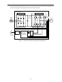
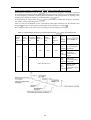
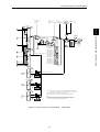
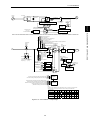
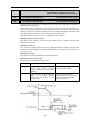
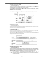
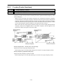
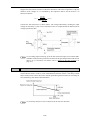
1.2 Control System
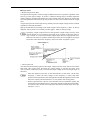
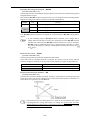
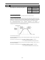
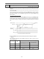
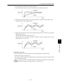
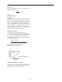
As shown in Figure 1.24, the converter section converts the input commercial power to DC power by
means of a full-wave rectifier, which charges the DC link bus capacitor (reservoir capacitor). The
inverter portion modulates the electric energy charged in the DC link bus capacitor by Pulse Width
Modulation (PWM) according to the control circuit signals and feeds the output to the motor. (The
PWMed frequency is called the "Carrier Frequency.")
The voltage applied to the motor has a waveform modulated by the carrier frequency from the
dynamic torque vector flux controller that estimates the optimal PWM signal monitoring the inverter
output current feedback, as shown on the left-hand side ("PWM voltage waveform") of Figure 1.23.
The voltage consists of alternating cycles of positive and negative pulse trains synchronizing with the
inverter’s output frequency.
The current running through the motor, on the other hand, has a fairly smooth alternating current (AC)
waveform shown on the right-hand side ("Current waveform") of Figure 1.23, thanks to the inductance
of the motor coil. The control block section controls the PWM so as to bring this current waveform as
close to a sinusoidal waveform as possible.
PWM voltage waveform
Current waveform
Figure 1.23 Output Voltage and Current Waveform of the Inverter
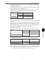
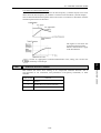
For the reference frequency given in the control block, the accelerator/decelerator processor calculates
the acceleration/deceleration rate required by run/stop control of the motor and transfers the calculated
results to the voltage calculator directly or via the dynamic torque vector flux controller, whose output
drives the PWM block to switch the power gates.
The FRENIC-Multi series features the dynamic torque vector controller with the flux estimator, which
is always correcting the magnetic flux phase while monitoring the inverter output current as the
feedback. This feature allows the inverter to always apply the drive power with an optimal voltage and
current and consequently respond to quick load variation or speed change.
The feature also estimates the generated torque of the motor from the estimated flux data and output
current to the motor to improve the motor efficiency for matching the current operation situation
1-11
INTRODUCTION TO FRENIC-Multi
This section gives you a general overview of inverter control systems and features specific to the
FRENIC-Multi series of inverters.
The control block section, which is the very brain of the inverter, allows you to customize the
inverter's driving patterns throughout the function code data settings.
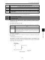
<Main circuit >
Converter
Inverter
DC link bus
capacitor
Power
supply
+
Frequency
command
Dynamic torque
vector controller
with flux estimator
or voltage calculator
Motor
M
<Control block>
Accelerator/
decelerator
processor
Current
detection
PWM
Figure 1.24 Schematic Overview Block Diagram of FRENIC-Multi
1-12
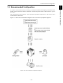
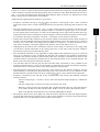
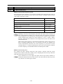
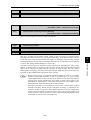
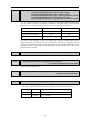
1.3 Recommended Configuration
After selecting the rated capacities, select appropriate peripheral equipment for the inverter, then
connect them to the inverter.
Figure 1.25 shows the recommended configuration for an inverter and peripheral equipment.
Figure 1.25 Recommended Configuration Diagram
1-13
INTRODUCTION TO FRENIC-Multi
To control a motor with an inverter correctly, you should consider the rated capacity of both the motor
and the inverter and ensure that the combination matches the specifications of the machine or system
to be used.
Chap. 1
1.3 Recommended Configuration
Chapter 2
PARTS NAMES AND FUNCTIONS
This chapter contains external views of the FRENIC-Multi series and an overview of terminal blocks,
including a description of the LED monitor, keys and LED indicators on the keypad.
Contents
2.1
2.2
External View and Allocation of Terminal Blocks...................................................................................... 2-1
LED Monitor, Keys and LED Indicators on the Keypad ............................................................................ 2-2
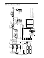
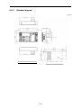
2.1 External View and Allocation of Terminal Blocks
2.1 External View and Allocation of Terminal Blocks
Chap. 2
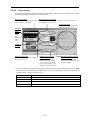
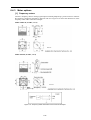
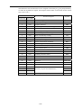
Figure 2.1 shows the external views of the FRENIC-Multi.
(1) External views
PARTS NAMES AND FUNCTIONS
Figure 2.1 FRN15E1S-2
(2) Terminal block location
(a) FRN0.75E1S-2
(b) FRN15E1S-2
Figure 2.2 Terminal Blocks
Note: A box () in the above model names replaces A, C, J, or K depending on the shipping destination.
Refer to Chapter 8 "SPECIFICATIONS" for details on terminal functions, arrangement and
connection and to Chapter 6, Section 6.2.1 "Recommended wires" when selecting wires.
For details on the keys and their functions, refer to Section 2.2 "LED Monitor, Keys and LED
Indicators on the Keypad." For details on keying operation and function code setting, refer to
Chapter 3 "OPERATION USING THE KEYPAD."
2-1
2.2 LED Monitor, Keys and LED Indicators on the Keypad
7-segment
LED monitor
As shown at the right, the keypad consists
of a four-digit LED monitor, six keys, and
five LED indicators.
The keypad allows you to run and stop
the motor, monitor running status, and
switch to the menu mode. In the menu
mode, you can set the function code data,
monitor I/O signal states, maintenance
information, and alarm information.
LED
indicators
RUN key
Program/
Reset key
RUN LED
Function/
Data key
STOP
key
UP key
DOWN key
Figure 2.3 Keypad
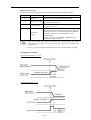
Table 2.1 Overview of Keypad Functions
Item
LED Monitor,
Keys, and
LED Indicators
Functions
Four-digit, 7-segment LED monitor which displays the followings according to the
operation modes.
In Running mode:
Running status information (e.g., output frequency, current,
and voltage)
In Programming mode: Menus, function codes and their data
In Alarm mode:
Alarm code, which identifies the alarm factor if the
protective function is activated.
LED
Monitor
Program/Reset key which switches the operation modes of the inverter.
In Running mode:
Pressing this key switches the inverter to Programming
mode.
In Programming mode: Pressing this key switches the inverter to Running mode.
In Alarm mode:
Pressing this key after removing the alarm factor will
switch the inverter to Running mode.
Function/Data key which switches the operation you want to do in each mode as
follows:
In Running mode:
Pressing this key switches the information to be displayed
concerning the status of the inverter (output frequency
(Hz), output current (A), output voltage (V), etc.).
In Programming mode: Pressing this key displays the function code and sets the
data entered with
and
keys.
In Alarm mode:
Pressing this key displays the details of the problem
indicated by the alarm code that has come up on the LED
monitor.
Operation
Keys
RUN key. Press this key to run the motor.
STOP key. Press this key to stop the motor.
and
UP and DOWN keys. Press these keys to select the setting items and change the
function code data displayed on the LED monitor.
RUN LED
Lights when any run command to the inverter is active.
key.
Lights when the inverter is ready to run with a run command entered by the
KEYPAD
(F02 = 0, 2, or 3) In Programming and Alarm modes, you cannot run the inverter even
CONTROL LED if the indicator lights.
LED
Indicators Unit and mode
expression by the
three LED
indicators
The three LED indicators identify the unit of numeral displayed on the LED monitor in
Running mode by combination of lit and unlit states of them.
Unit: kW, A, Hz, r/min and m/min
Refer to Chapter 3, Section 3.2.1 "Monitoring the running status" for details.
While the inverter is in Programming mode, the LEDs of Hz and
Hz
kW light.
A
kW
2-2
2.2 LED Monitor, Keys and LED Indicators on the Keypad
LED monitor
If one of LED4 through LED1 is blinking, it means that the cursor is at this digit, allowing you to
change it.
Figure 2.4 7-Segment LED Monitor
Table 2.2 Alphanumeric Characters on the LED Monitor
Character
7-segment
Character
7-segment
Character
7-segment
Character
7-segment
0
0
9
9
i
i
r
r
1
1
A
a
J
j
S
Ss
2
2
b
Bb
K
k
T
T
3
3
C
Cc
L
l
u
U
4
4
d
d
M
m
V
u
5
5
E
e
n
n
W
w
6
6
F
f
o
o
X
x
7
7
G
g
P
p
y
y
8
8
H
h
q
q
Z
Z
Special characters and symbols (numbers with decimal point, minus and underscore)
0. - 9.
* –)
-
-
_
_
Simultaneous keying
Simultaneous keying means pressing two keys at the same time. The FRENIC-Multi supports
simultaneous keying as listed below. The simultaneous keying operation is expressed by a "+" letter
between the keys throughout this manual.
(For example, the expression "
key.)
+
keys" stands for pressing the
key while holding down the
Table 2.3 Simultaneous Keying
Operation mode
Simultaneous keying
+
keys
+
keys
+
keys
Used to:
Change certain function code data. (Refer to codes F00,
H03, H45, and H97 in Chapter 9 "FUNCTION CODES.")
Programming mode
Alarm mode
Switch to Programming mode without resetting alarms
currently occurred.
2-3
PARTS NAMES AND FUNCTIONS
If the decimal point of LED1 is blinking, it means that the currently displayed data is a value of the
PID process command, not the frequency data usually displayed.
Chap. 2
In Running mode, the LED monitor displays running status information (output frequency, current or
voltage); in Programming mode, it displays menus, function codes and their data; and in Alarm mode,
it displays an alarm code which identifies the alarm factor if the protective function is activated.
Chapter 3
OPERATION USING THE KEYPAD
This chapter describes inverter operation using the keypad. The inverter features three operation modes
(Running, Programming and Alarm modes) which enable you to run and stop the motor, monitor running
status, configure function code data, display running information required for maintenance, and display
alarm data.
The keypad is available in two types: standard keypad and optional multi-function keypad. For the
instructions on how to operate the multi-function keypad, refer to the "Multi-function Keypad Instruction
Manual."
Contents
3.1 Overview of Operation Modes.................................................................................................................... 3-1
3.2 Running Mode ............................................................................................................................................ 3-3
3.2.1 Monitoring the running status ............................................................................................................. 3-3
3.2.2 Setting up frequency and PID commands ........................................................................................... 3-4
3.2.3 Running/stopping the motor................................................................................................................ 3-9
3.2.4 Jogging Operation ............................................................................................................................... 3-9
3.3 Programming Mode .................................................................................................................................. 3-10
3.3.1 Setting up basic function codes quickly -- Menu #0 "Quick Setup" --.............................................. 3-12
3.3.2 Setting up function codes -- Menu #1 "Data Setting" --................................................................... 3-16
3.3.3 Checking changed function codes -- Menu #2 "Data Checking" -- .................................................. 3-17
3.3.4 Monitoring the running status -- Menu #3 "Drive Monitoring" -- ................................................... 3-18
3.3.5 Checking I/O signal status -- Menu #4 "I/O Checking" -- ............................................................... 3-21
3.3.6 Reading maintenance information -- Menu #5 "Maintenance Information" -- ................................ 3-26
3.3.7 Reading alarm information -- Menu #6 "Alarm Information" --...................................................... 3-29
3.4 Alarm Mode .............................................................................................................................................. 3-32
3.4.1 Releasing the alarm and switching to Running mode ....................................................................... 3-32
3.4.2 Displaying the alarm history ............................................................................................................. 3-32
3.4.3 Displaying the status of inverter at the time of alarm ....................................................................... 3-32
3.4.4 Switching to Programming mode...................................................................................................... 3-32
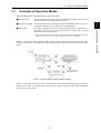
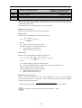
3.1 Overview of Operation Modes
3.1
Overview of Operation Modes
FRENIC-Multi features the following three operation modes:
■ Running mode
: This mode allows you to enter run/stop commands in regular operation. You
can also monitor the running status in real time.
■ Alarm mode
* Alarm code: Indicates the cause of the alarm condition that has triggered a protective
function. For details, refer to Chapter 8, Section 8.7 "Protective Functions."
Figure 3.1 shows the status transition of the inverter between these three operation modes. If the
inverter is turned ON, it automatically enters Running mode, making it possible to start or stop the
motor.
Figure 3.1 Status Transition between Operation Modes
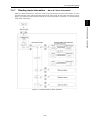
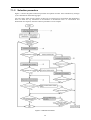
Figure 3.2 illustrates the transition of the LED monitor screen during Running mode, the transition
between menu items in Programming mode, and the transition between alarm codes at different
occurrences in Alarm mode.
3-1
OPERATION USING THE KEYPAD
: If an alarm condition arises, the inverter automatically enters Alarm mode. In
this mode, you can view the corresponding alarm code* and its related
information on the LED monitor.
Chap. 3
■ Programming mode : This mode allows you to configure function code data and check a variety of
information relating to the inverter status and maintenance.
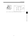
(*1) The speed monitor allows you to select the desired one from the seven speed monitor items by using function
code E48.
(*2) Applicable only when PID control is active (J01 = 1, 2 or 3).
(*3) The Timer screen appears only when the timer operation is enabled with function code C21.
(*4) Applicable only when the full-menu mode is selected (E52 = 2).
Figure 3.2 Transition between Basic Screens in Individual Operation Mode
3-2
3.2 Running Mode
3.2
Running Mode
When the inverter is turned on, it automatically enters Running mode in which you can:
Monitor the running status (e.g., output frequency and output current),
Configure the reference frequency and other settings,
Run/stop the motor, and
Jog (inch) the motor.
Chap. 3
(1)
(2)
(3)
(4)
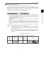
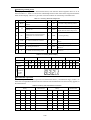
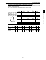
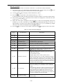
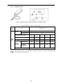
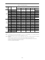
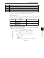
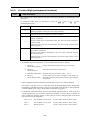
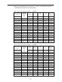
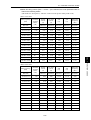
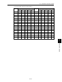
In Running mode, the eleven items listed below can be monitored. Immediately after the inverter is
key to switch
turned on, the monitor item specified by function code E43 is displayed. Press the
key, refer to
between monitor items. For details of switching the monitor item by using the
"Monitor of running status" in the Running mode in Figure 3.2.
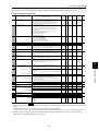
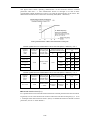
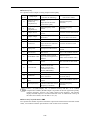
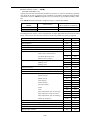
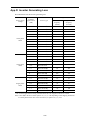
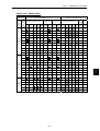
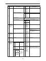
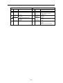
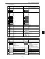
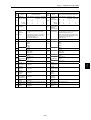
Table 3.1 Monitoring Items
Monitor items
Speed monitor
Display
LED indicator
sample on
Unit
Meaning of displayed value
the LED
: on, : off
monitor *1
Function code E48 specifies what to be displayed on the LED monitor and LED
indicators.
Function
code data
for E43
0
Output
frequency
(before slip
compensation)
5*00
Hz A kW
Hz
Frequency actually being output
(E48 = 0)
Output
frequency
(after slip
compensation)
5*00
Hz A kW
Hz
Frequency actually being output
(E48 = 1)
Reference
frequency
5*00
Hz A kW
Hz
Reference frequency being set
(E48 = 2)
Motor speed
1500
Hz A kW
r/min
120
P01
For motor 2, read P01 as A15.
(E48 = 3)
Load shaft speed
30*0
Hz A kW
r/min
Output frequency (Hz) × E50
(E48 = 4)
Line speed
30*0
Hz A kW
m/min
Output frequency (Hz) × E50
(E48 = 5)
50
Hz A kW
min
E50
Output frequency (Hz) × E39
(E48 = 6)
Output current
1"34
Hz A kW
A
Current output from the inverter in RMS
3
Output voltage *2
200u
Hz A kW
V
Voltage output from the inverter in RMS
4
Calculated torque
50
Hz A kW
%
Motor output torque in % (Calculated
value)
8
Input power
1*25
Hz A kW
kW
Input power to the inverter
9
PID command
*3, *4
1*0*
Hz A kW
−
PID feedback
amount
*3, *5
)0*
Hz A kW
−
PID command/feedback amount
transformed to that of virtual physical
value of the object to be controlled
(e.g. temperature)
Refer to function codes E40 and E41 for
details.
50
Hz A kW
min
10**
Hz A kW
%
Constant feeding
rate time
Timer (Timer
operation)
*3
PID output *3, *4
Output frequency (Hz) ×
10
12
Remaining time of timer operation
13
PID output in % as the maximum
frequency (F03) being at 100%
14
For motor 2, read F03 as A01.
Load factor
*6
50;
Hz A kW
%
Motor output
*7
)85
Hz A kW
kW
3-3
Load factor of the motor in % as the
rated output being at 100%
15
Motor output in kW
16
OPERATION USING THE KEYPAD
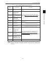
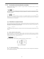
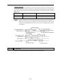
3.2.1 Monitoring the running status
*1 A value exceeding 9999 cannot be displayed on the 4-digit LED monitor screen, so "
" appear instead.
*2 When the LED monitor displays an output voltage, the 7-segment letter u in the lowest digit stands for the unit of
the voltage "V."
-
*3 These PID-related items appear only when the inverter PID-controls the motor according to a PID command
specified by function code J01 (=1, 2 or 3).
The Timer item appears only when the timer operation is enabled with function code C21. (Refer to Chapter 9,
Section 9.2.3 "C codes (Control Functions)".)
When the PID control or timer operation is disabled, "
" appear.
*4 When the LED monitor displays a PID command or its output amount, the dot (decimal point) attached to the
lowest digit of the 7-segment letter blinks.
*5 When the LED monitor displays a PID feedback amount, the dot (decimal point) attached to the lowest digit of the
7-segment letter lights.
*6 When the LED monitor displays a load factor, the 7-segment letter ; in the lowest digit stands for "%."
*7 When the LED monitor displays the motor output, the unit LED indicator "kW" blinks.
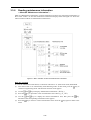
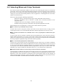
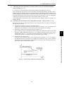
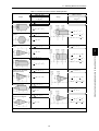
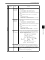
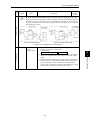
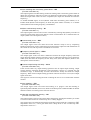
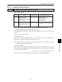
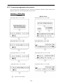
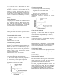
3.2.2 Setting up frequency and PID commands
You can set up the desired frequency and PID commands by using
and
keys on the keypad. It is
also possible to set up the frequency command as load shaft speed, motor speed or speed (%) by
setting function code E48.
■ Setting up a frequency command
Using
and
keys (Factory default)
(1) Set function code F01 to "0:
in Running mode.
(2) Press the
/
/
keys on keypad." This can be done only when the inverter is
key to display the current reference frequency. The lowest digit will blink.
/
key again. The new setting will
(3) If you need to change the frequency command, press the
be automatically saved into the inverter's internal memory and retained even when the power is
off. When the power is turned on next time, the setting will be used as an initial reference
frequency.
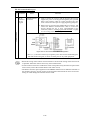
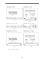
• If you have set function code F01 to "0:
/
keys on keypad" but have selected a
frequency command source other than frequency command 1 (i.e., frequency command
2, frequency command via communication, or multi-frequency command), then the
and
keys are disabled to change the current frequency command even in Running
mode. Pressing either of these keys just displays the current reference frequency.
• When you start specifying the reference frequency or any other parameter with the
/
key, the least significant digit on the display blinks; that is, the cursor lies in the least
/
key changes data in the least significant digit
significant digit. Holding down the
and generates a carry, while the cursor remains in the least significant digit.
• After the least significant digit blinks by pressing the
/
key, holding down the
key for more than 1 second moves the cursor from the least significant digit to the most
significant digit. Further holding it down moves the cursor to the next lower digit. This
cursor movement allows you to easily move the cursor to the desired digit and change the
data in higher digits.
/
keys on keypad" and selecting frequency
• By setting function code C30 to "0:
command 2, you can also specify or change the frequency command in the same manner
/
key.
using the
You can set a reference frequency not only with the frequency (Hz) but also with other menu items
(motor speed, load shaft speed, line speed and constant feeding rate time) depending on the setting of
function code E48 (= 3, 4, 5 or 6) as listed in Table 3.1.
3-4
3.2 Running Mode
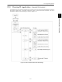
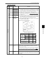
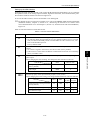
■ Settings under PID process control
To enable the PID process control, you need to set function code J01 to "1" or "2."
Refer to Chapter 4, Section 4.5, "PID Process Control Block."
(1) Set function code J02 to "0:
/
and
keys
keys on keypad."
(2) Set the LED monitor to something other than the speed monitor (E43=0) when the inverter is in
Running mode. When the keypad is in Programming or Alarm mode, you cannot modify the PID
/
key. To enable the PID process command to be modified
process command with the
with the
/
key, first switch to Running mode.
(3) Press the
/
key to display the PID process command. The lowest digit and its decimal
point blinks on the LED monitor.
(4) To change the PID process command, press the
/
key again. The PID process command
you have specified will be automatically saved into the inverter’s internal memory. It is retained
even if you temporarily switch to another PID process command source and then go back to the
via-keypad PID process command. Also, it is retained in the memory even while the inverter is
powered off, and will be used as the initial PID process command next time the inverter is
powered on.
•
•
•
Even if multi-frequency is selected as a PID process command (SS4 or SS8 = ON), you
still can set the process command using the keypad.
/
key
When function code J02 is set to any value other than "0," pressing the
displays, on the 7-segment LED monitor, the PID process command currently selected,
while you cannot change the setting.
On the 7-segment LED monitor, the decimal point of the lowest digit is used to
characterize what is displayed. The decimal point of the lowest digit blinks when a PID
process command is displayed; the decimal point lights when a PID feedback amount is
displayed.
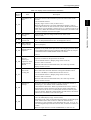
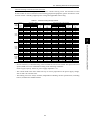
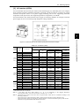
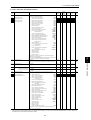
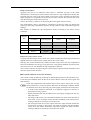
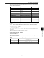
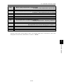
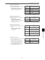
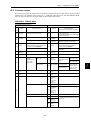
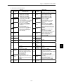
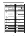
Table 3.2 PID Process Command Manually Set with
PID control
(Mode
selection)
J01
PID control
(Remote command
SV)
J02
LED Monitor
E43
/
Multifrequency
SS4, SS8
0
1 or 2
Key and Requirements
With
/
key
PID process command by keypad
Other than 0
Other than 0
3-5
ON or OFF
PID process command currently
selected
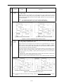
OPERATION USING THE KEYPAD
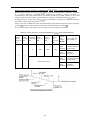
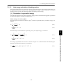
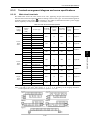
Setting the PID process command with
Chap. 3
Under the PID control, the items that can be specified or checked with
and
keys are different
from those under regular frequency control, depending upon the current LED monitor setting. If the
LED monitor is set to the speed monitor (E43 = 0), you can access manual speed commands
and
keys; if it is set to any other, you can access the PID process
(frequency command) with
command with those keys.
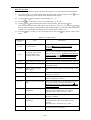
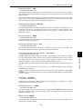
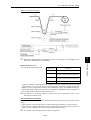
Setting up the frequency command with
and
keys under PID process control
keys on keypad) and frequency command 1 is selected
When function code F01 is set to "0" ( /
as a manual speed command (when disabling the frequency setting command via communications link
or multi-frequency command), switching the LED monitor to the speed monitor in Running mode
keys.
/
enables you to modify the frequency command with the
In Programming or Alarm mode, the
You need to switch to Running mode.
/
keys are disabled to modify the frequency command.
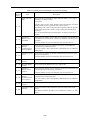
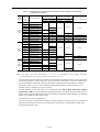
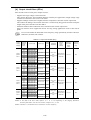
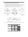
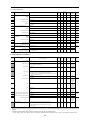
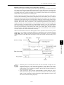
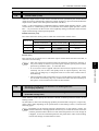
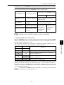
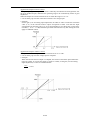
Table 3.3 lists the combinations of the commands and the figure illustrates how the manual speed
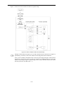
command entered via the keypad is translated to the final frequency command .
The setting procedure is the same as that for setting of a usual frequency command.
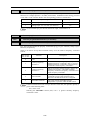
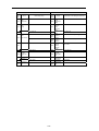
Table 3.3 Manual Speed (Frequency) Command Specified with
PID
control
(Mode
selection)
J01
LED
Frequency Multimonitor command 1 frequency
E43
F01
SS2
Multifrequency
SS1
/
Communications
link
operation
LE
Keys and Requirements
Cancel
PID
control
Hz/PID
Pressing
/
keys controls:
OFF
PID output
(PID
(as final frequency
enabled) command)
0
1 or 2
OFF
OFF
OFF
Manual speed
ON
(frequency)
(PID
command set by
disabled)
keypad
0
OFF
PID output
(PID
(as final frequency
enabled) command)
Other than the above
3-6
Manual speed
ON
(frequency)
(PID
command currently
disabled)
selected
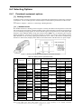
3.2 Running Mode
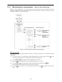
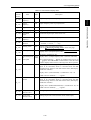
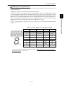
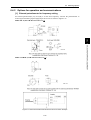
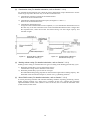
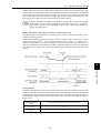
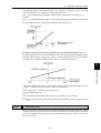
■ Settings under PID dancer control
To enable the PID dancer control, you need to set function code J01 to "3."
Under the PID control, the items that can be specified or checked with
and
keys are different
from those under the regular frequency control, depending upon the current LED monitor setting. If
the LED monitor is set to the speed monitor (E43 = 0), the item accessible is the primary frequency
command; if it is set to any other data, it is the PID dancer position command.
Chap. 3
Refer to Chapter 4, Section 4.6, "PID Dancer Control Block."
(1) Set function code J02 to "0:
/
and
keys
keys on keypad."
(2) Set the LED monitor to something other than the speed monitor (E43=0) when the inverter is in
Running mode. When the keypad is in Programming or Alarm mode, you cannot modify the PID
/
key. To enable the PID dancer position command to be modified with
command with the
the
/
key, first switch to Running mode.
(3) Press the
/
LED monitor.
key to display the PID dancer position command. The lowest digit blinks on the
(4) To change the command, press the
/
key again. The command you have specified will be
automatically saved into the inverter’s internal memory as function code J57 data. It is retained
even if you temporarily switch to another PID command source and then go back to the
via-keypad PID command. Furthermore, you can directly configure the command with function
code J57.
•
•
•
Even if multi-frequency is selected as a PID command (SS4 or SS8 = ON), you still can
set the PID dancer position command using the keypad.
/
key
When function code J02 is set to any value other than "0," pressing the
displays, on the 7-segment LED monitor, the PID command currently selected, while you
cannot change the setting.
On the 7-segment LED monitor, the decimal point of the lowest digit is used to
characterize what is displayed. The decimal point of the lowest digit blinks when a PID
command is displayed; the decimal point lights when a PID feedback amount is
displayed.
Table 3.4 PID Command Manually Set with
PID control
(Mode
selection)
J01
PID control
(Remote command LED monitor
SV)
E43
J02
/
Multifrequency
SS4, SS8
0
3
Key and Requirements
With
/
key
PID command by keypad
Other than 0
Other than 0
ON or OFF
PID command currently selected
3-7
OPERATION USING THE KEYPAD
Setting the PID dancer position command with the
Setting up the primary frequency command with
and
keys under PID dancer control
keys on keypad) and frequency command 1 is selected
When function code F01 is set to "0" ( /
as a primary frequency command (when disabling the frequency setting command via
communications link and multi-frequency command), switching the LED monitor to the speed
keys.
/
monitor in Running mode enables you to modify the frequency command with the
In Programming or Alarm mode, the
You need to switch to Running mode.
/
keys are disabled to modify the frequency command.
Table 3.5 lists the combinations of the commands and the figure illustrates how the primary frequency
command entered via the keypad is translated to the final frequency command .
The setting procedure is the same as that for setting of a usual frequency command.
Table 3.5 Primary Frequency Command Specified with
PID
control
(Mode
selection)
J01
LED
Frequency Multimonitor command 1 frequency
E43
F01
SS2
Multifrequency
SS1
/
Communications
link
operation
LE
Keys and Requirements
Cancel
PID
control
Hz/PID
Pressing
/
keys controls:
OFF
Final frequency
(PID
command modified
enabled) by PID output
0
OFF
OFF
OFF
ON
Keypad primary
(PID
command
disabled) (Frequency)
3
0
OFF
Final frequency
(PID
command modified
enabled) by PID output
Other than the above
ON
Current primary
(PID
command
disabled) (Frequency)
3-8
3.2 Running Mode
3.2.3 Running/stopping the motor
By factory default, pressing the
key starts
running the motor in the forward direction and
key decelerates the motor to stop.
pressing the
key is enabled only in Running mode.
The
Chap. 3
The motor rotational direction can be selected by
changing the setting of function code F02.
Table 3.6 lists the relationship between function code F02 settings and the
the motor rotational direction.
key
key, which determines
Table 3.6 Motor Rotational Direction Specified by F02
Data for F02
Pressing the
key runs the motor:
In the direction commanded by terminal
[FWD] or [REV]
0
key disabled
1
(The motor is driven by terminal [FWD] or
[REV] command.)
2
In the forward direction
3
In the reverse direction
(Note) The rotational direction of
IEC-compliant motors is opposite to
that of the motor shown here.
For the details on operations with function code F02, refer to Chapter 9 "FUNCTION CODES."
3.2.4 Jogging Operation
This section provides the procedure for jogging the motor.
(1)
Making the inverter ready to jog with the steps below. The LED monitor should display jog .
Enter Running mode (see page 3-2) and press the
+
keys simultaneously.
The LED monitor displays the jogging frequency for approximately one second and then returns
to jog again.
•
•
•
(2)
Function codes C20 and H54 specify the jogging frequency and acceleration/deceleration
time, respectively. Use these function codes exclusively for the jogging operation with
your needs.
Using the input terminal command "Ready for jogging" JOG switches between the
normal operation state and ready-to-jog state.
+
Switching between the normal operation state and read-to-jog state with the
keys is possible only when the inverter is stopped.
Jogging the motor.
Hold down the
key during which the motor continues jogging. To decelerate to stop the
motor, release the key.
(3)
Exiting the ready-to-jog state and returning to the normal operation state.
• Press the
+
keys simultaneously.
For details, refer to the descriptions of function codes E01 to E05 in Chapter 9, Section 9.2.2 "E
codes (Terminal functions)."
3-9
OPERATION USING THE KEYPAD
■ Operational relationship between function code F02 (Operation method) and
3.3
Programming Mode
The Programming mode provides you with these functions--setting and checking function code data,
monitoring maintenance information and checking input/output (I/O) signal status. The functions can
be easily selected with the menu-driven system. Table 3.7 lists menus available in Programming mode.
The leftmost digit (numerals) of each letter string on the LED monitor indicates the corresponding
menu number and the remaining three digits indicate the menu contents.
When the inverter enters Programming mode from the second time on, the menu selected last in
Programming mode will be displayed.
Table 3.7 Menus Available in Programming Mode
Menu #
0
1
Menu
"Quick Setup"
LED
monitor
shows:
Main functions
Refer to:
*fn:
Displays only basic function codes to customize
the inverter operation.
Section
3.3.1
!f__
F codes
(Fundamental functions)
!e__
E codes
(Extension terminal
functions)
!c__
C codes
(Control functions)
!p__
P codes
(Motor 1 parameters)
!h__
H codes
(High performance
functions)
!a__
A codes
(Motor 2 parameters)
!j__
J codes
(Application functions)
!y__
!o__
y codes (Link functions)
"Data Setting"
Selecting each of
these function
codes enables its
data to be
displayed/changed.
Section
3.3.2
o codes (Optional function)
2
"Data
Checking"
"rep
Displays only function codes that have been
changed from their factory defaults. You can refer
to or change those function code data.
Section
3.3.3
3
"Drive
Monitoring"
#ope
Displays the running information required for
maintenance or test running.
Section
3.3.4
4
"I/O Checking"
$i_o
Displays external interface information.
Section
3.3.5
5
"Maintenance
Information"
%che
Displays maintenance information including
cumulative run time.
Section
3.3.6
6
"Alarm
Information"
&al
Displays the latest four alarm codes. You can
refer to the running information at the time when
the alarm occurred.
Section
3.3.7
(Note 1) Mounting a multi-function keypad adds the data copying function to the menu, enabling reading,
writing, and verifying of function code data.
(Note 2) The o codes are displayed only when the corresponding option is mounted. For details, refer to the
Instruction Manual for the corresponding option.
3-10
3.3 Programming Mode
Figure 3.3 illustrates the menu-driven function code system in Programming mode.
Chap. 3
OPERATION USING THE KEYPAD
Figure 3.3 Menu Transition in Programming Mode
3-11
■ Selecting menus to display
The menu-driven system allows you to cycle through menus. To cycle through necessary menus only
for simple operation, use function code E52 that provides a choice of three display modes as listed
below.
The factory default (E52 = 0) is to display only two menus--Menu #0 "Quick Setup" and Menu #1
"Data Setting," allowing no switching to any other menu.
Table 3.8 Keypad Display Mode Selection – Function Code E52
Data for E52
Mode
Menus selectable
0
Function code data editing mode (factory default)
Menu #0 "Quick Setup"
Menu #1 "Data Setting"
1
Function code data check mode
Menu #2 "Data Checking"
2
Full-menu mode
Menus #0 through #6
Pressing the
/
key will cycle through the menu. With the
key, you can select the
desired menu item. Once the entire menu has been cycled through, the display will return to
the first menu item.
3.3.1
Setting up basic function codes quickly
-- Menu #0 "Quick Setup" --
Menu #0 "Quick Setup" in Programming mode allows you to quickly display and set up a basic set of
function codes specified in Chapter 9, Section 9.1, "Function Code Tables."
To use Menu #0 "Quick Setup," you need to set function code E52 to "0" (Function code data editing
mode) or "2" (Full-menu mode).
The predefined set of function codes that are subject to quick setup are held in the inverter.
3-12
3.3 Programming Mode
Listed below are the function codes (including those not subject to quick setup) available on the
FRENIC-Multi. A function code is displayed on the LED monitor on the keypad in the following
format:
Chap. 3
ID number in each function code group
Function code group
Table 3.9 Function Codes Available on FRENIC-Multi
Function
Description
F codes
F00 to F51
Fundamental
functions
Functions concerning basic motor
running
E codes
E01 to E99
Extension terminal
functions
Functions concerning the assignment
of control circuit terminals
Functions concerning the display of
the LED monitor
C codes
C01 to C53
Control functions
Functions associated with frequency
settings
P codes
P01 to P99
Motor 1 parameters
Functions for setting up
characteristics parameters (such as
capacity) of the motor
H codes
H03 to H98
High performance
functions
Highly added-value functions
Functions for sophisticated control
A codes
A01 to A46
Motor 2 parameters
Functions for setting up
characteristics parameters (such as
capacity) of the motor
J codes
J01 to J86
Application functions
Functions for applications such as
PID control
y codes
y01 to y99
Link functions
Functions for controlling
communication
o codes
o27 to o59
Optional functions
Functions for options (Note)
(Note) The o codes are displayed only when the corresponding option is mounted. For details of the o codes, refer to
the Instruction Manual for the corresponding option.
For the list of function codes subject to quick setup and their descriptions, refer to Chapter 9,
Section 9.1 "Function Code Tables."
Function codes requiring simultaneous keying
To modify the data for function code F00 (Data Protection), H03 (Data Initialization), H45 (Mock
keys or
+
Alarm), or H97 (Clear Alarm Data), simultaneous keying is needed, involving the
keys.
+
Changing, validating, and saving function code data when the inverter is running
Some function code data can be changed while the inverter is running, whereas others cannot. Further,
depending on the function code, modifications may or may not validate immediately. For details, refer
to the "Change when running" column in Chapter 9, Section 9.1 " Function Code Tables."
For details of function codes, refer to Chapter 9, Section 9.1 " Function Code Tables."
3-13
OPERATION USING THE KEYPAD
Function Code Group Function Codes
Figure 3.4 shows the menu transition in Menu #0 "Quick Setup."
Figure 3.4 Menu Transition in Menu #0 "Quick Setup"
Through a multi-function keypad, you can add or delete function codes that are subject to
Quick Setup. For details, refer to the "Multi-function Keypad Instruction Manual."
Once you have added or deleted function codes for Quick Setup through a multi-function
keypad, they will remain valid even after you switch to a standard keypad. To restore the
function code settings subject to Quick Setup to their factory defaults, initialize the whole
data using function code H03 (data = 1).
3-14
3.3 Programming Mode
Basic key operation
This section gives a description of the basic key operation, following the example of the function code
data changing procedure shown in Figure 3.5.
This example shows you how to change function code F01 data from the factory default "
/
keys
on keypad (F01 = 0)" to "Current input to terminal [C1] (C1 function) (4 to 20 mA DC)
(F01 = 2)."
(3) Press the
and
keys to display *fn:.
key to proceed to a list of function codes.
and
keys to display the desired function code (f 01 in this example), then press
(4) Use the
key.
the
The data of this function code appears. (In this example, data 0 of f 01 appears.)
(5) Change the function code data using the
times to change data 0 to 2.)
and
keys. (In this example, press the
key two
key to establish the function code data.
(6) Press the
The saue appears and the data will be saved in the memory inside the inverter. The display will
return to the function code list, then move to the next function code. (In this example, f 02.)
Pressing the
key instead of the
key cancels the change made to the data. The data reverts
to the previous value, the display returns to the function code list, and the original function code
reappears.
(7) Press the
key to return to the menu from the function code list.
Cursor movement
key for
You can move the cursor when changing function code data by holding down the
1 second or longer in the same way as with the frequency settings. This action is called
"Cursor movement."
Figure 3.5 Example of Function Code Data Changing Procedure
3-15
OPERATION USING THE KEYPAD
(2) If anything other than *fn: is displayed, use the
Chap. 3
key to
(1) Turn the inverter on. It automatically enters Running mode. In that mode, press the
switch to Programming mode. The function selection menu appears. (In this example, *fn: is
displayed.)
3.3.2
Setting up function codes
-- Menu #1 "Data Setting" --
Menu #1 "Data Setting" in Programming mode allows you to set up function codes for making the
inverter functions match your needs.
To set function codes in this menu, it is necessary to set function code E52 to "0" (Function code data
editing mode) or "2" (Full-menu mode).
Basic key operation
For details of the basic key operation, refer to Menu #0 "Quick Setup" in Section 3.3.1.
3-16
3.3 Programming Mode
3.3.3
Checking changed function codes -- Menu #2 "Data Checking" --
Menu #2 "Data Checking" in Programming mode allows you to check function codes that have been
changed. Only the function codes whose data has been changed from the factory defaults are displayed
on the LED monitor. You can refer to the function code data and change it again if necessary. Figure
3.6 shows the menu transition in Menu #2 "Data Checking."
Chap. 3
OPERATION USING THE KEYPAD
Figure 3.6 Menu Transition in Menu #2 "Data Checking" (Changing F01, F05 and E52 data only)
Basic key operation
For details of the basic key operation, refer to Menu #0 "Quick Setup" in Section 3.3.1.
To check function codes in Menu #2 "Data Checking," it is necessary to set function code
E52 to "1" (Function code data check mode) or "2" (Full-menu mode).
For details, refer to "■ Selecting menus to display" on page 3-12.
3-17
3.3.4
Monitoring the running status
-- Menu #3 "Drive Monitoring" --
Menu #3 "Drive Monitoring" is used to monitor the running status during maintenance and trial
running. The display items for "Drive Monitoring" are listed in Table 3.10. Figure 3.7 shows the menu
transition in Menu #3 "Drive Monitoring."
Figure 3.7 Menu Transition in Menu #3 "Drive Monitoring"
Basic key operation
To monitor the running status on the drive monitor, set function code E52 to "2" (Full-menu mode)
beforehand.
(1) Turn the inverter on. It automatically enters Running mode. In that mode, press the
switch to Programming mode. The function selection menu appears.
(2) Use the
(3) Press the
and
keys to display "Drive Monitoring" (#ope ).
key to proceed to a list of monitoring items (e.g. 3_00 ).
and
keys to display the desired monitoring item, then press the
(4) Use the
The running status information for the selected item appears.
(5) Press the
menu.
key to
key to return to a list of monitoring items. Press the
3-18
key.
key again to return to the
3.3 Programming Mode
Table 3.10 Drive Monitor Display Items
LED
monitor
shows:
Item
Unit
Description
Hz
Output frequency before slip compensation
3_01
Output
frequency
Hz
Output frequency after slip compensation
3_02
Output current
A
Output current
3_03
Output voltage
V
Output voltage
3_04
Calculated
torque
%
Calculated output torque of the motor in %
3_05
Reference
frequency
Hz
Frequency specified by a frequency command
3_06
Rotational
direction
N/A
3_07
Running status
N/A
Running status in hexadecimal format
Refer to " Displaying running status" on the next page.
Motor speed
r/min
Display value = (Output frequency Hz) ×
-
3_08
Rotational direction being outputted
: stop
f: forward, r: reverse,
120
(Function code P01)
For motor 2, read P01 as A15.
3_09
Load shaft speed r/min Display value = (Output frequency Hz) × (Function code E50)
or
m/min
The 7-segment letters
appear for 10000 (r/min) or more. If
Line speed
appear, decrease function code E50 data so that the LED
monitor displays 9999 or below, referring to the above equation.
PID command
N/A
3_10
Virtual physical value (e.g., temperature or pressure) of the
object to be controlled, which is converted from the PID
command using function code E40 and E41 data (PID display
coefficients A and B)
Display value = (PID command) × (Coefficient A - B) + B
PID feedback
amount
N/A
3_11
-
If PID control is disabled, "
" appears.
Virtual physical value (e.g., temperature or pressure) of the
object to be controlled, which is converted from the PID
command using function code E40 and E41 data (PID display
coefficients A and B)
Display value = (PID feedback amount) × (Coefficient A - B) + B
-
If PID control is disabled, "
" appears.
3_12
Torque limit
value (Level 1)
%
Driving torque limit value (based on motor rated torque)
3_13
Torque limit
value (Level 2)
%
Braking torque limit value (based on motor rated torque)
3-19
OPERATION USING THE KEYPAD
Output
frequency
Chap. 3
3_00
Displaying running status
To display the running status in hexadecimal format, each state has been assigned to bits 0 to 15 as
listed in Table 3.11. Table 3.12 shows the relationship between each of the status assignments and the
LED monitor display. Table 3.13 gives the conversion table from 4-bit binary to hexadecimal.
Table 3.11 Running Status Bit Assignment
Bit
Notation
Content
Bit
Notation
15
BUSY
"1" when function code data is being
written.
7
VL
"1" under voltage limiting control.
Always "0."
6
TL
"1" under torque limiting control.
Always "0."
5
NUV
"1" when the DC link bus voltage is
higher than the undervoltage level.
"1" when communication is enabled
(when ready for run and frequency
commands via communications
link).
4
BRK
"1" during braking.
14
WR
13
Content
12
RL
11
ALM
"1" when an alarm has occurred.
3
INT
"1" when the inverter output is shut
down.
10
DEC
"1" during deceleration.
2
EXT
"1" during DC braking.
9
ACC
"1" during acceleration.
1
REV
"1" during running in the reverse
direction.
8
IL
"1" under current limiting control.
0
FWD
"1" during running in the forward
direction.
Table 3.12 Running Status Display
LED No.
LED4
Bit
15
Notation
BUSY
Binary
Example
14
1
LED3
13
WR
0
12
11
10
9
RL ALM DEC ACC
0
0
0
0
1
LED2
8
7
IL
VL
1
0
6
5
LED1
4
3
2
1
0
TL NUV BRK INT EXT REV FWD
0
1
0
0
0
0
1
Hexadecimal on
the LED
monitor
Hexadecimal expression
A 4-bit binary number can be expressed in hexadecimal format (1 hexadecimal digit). Table 3.13
shows the correspondence between the two notations. The hexadecimals are shown as they appear on
the LED monitor.
Table 3.13 Binary and Hexadecimal Conversion
Binary
Hexadecimal
Binary
Hexadecimal
0
0
0
0
0
1
0
0
0
8
0
0
0
1
1
1
0
0
1
9
0
0
1
0
2
1
0
1
0
a
0
0
1
1
3
1
0
1
1
b
0
1
0
0
4
1
1
0
0
c
0
1
0
1
5
1
1
0
1
d
0
1
1
0
6
1
1
1
0
e
0
1
1
1
7
1
1
1
1
f
3-20
3.3 Programming Mode
3.3.5
Checking I/O signal status
-- Menu #4 "I/O Checking" --
Using Menu #4 "I/O Checking" displays the I/O status of external signals including digital and analog
I/O signals without using a measuring instrument. Table 3.14 lists check items available. The menu
transition in Menu #4 "I/O Checking" is shown in Figure 3.8.
Chap. 3
OPERATION USING THE KEYPAD
Figure 3.8 Menu Transition in Menu #4 "I/O Checking"
3-21
Basic key operation
To check the status of the I/O signals, set function code E52 to "2" (Full-menu mode) beforehand.
(1) Turn the inverter on. It automatically enters Running mode. In that mode, press the
switch to Programming mode. The function selection menu appears.
(2) Use the
(3) Press the
and
key to
keys to display "I/O Checking" ($i_o).
key to proceed to a list of I/O check items (e.g. 4_00 ).
and
keys to display the desired I/O check item, then press the
key.
(4) Use the
The corresponding I/O check data appears. For the item 4_00 or 4_01, using the
and
keys switches the display method between the segment display (for external signal information
in Table 3.15) and hexadecimal display (for I/O signal status in Table 3.16).
(5) Press the
menu.
key to return to a list of I/O check items. Press the
key again to return to the
Table 3.14 I/O Check Items
LED monitor
shows:
4_00
Item
Description
I/O signals on the control
circuit terminals
Shows the ON/OFF state of the digital I/O terminals.
Refer to " Displaying control I/O signal
terminals" on the next page for details.
4_01
I/O signals on the control
circuit terminals under
communications control
Shows the ON/OFF state of the digital I/O terminals
that received a command via RS-485 and optional
communications. Refer to " Displaying control I/O
signal terminals" and " Displaying control I/O
signal terminals under communications control"
on the following pages for details.
4_02
Input voltage on terminal [12]
Shows the input voltage on terminal [12] in volts (V).
4_03
Input current on terminal [C1]
Shows the input current on terminal [C1] in
milliamperes (mA).
4_04
Output voltage to analog
meters [FM]
Shows the output voltage on terminal [FM] in volts
(V).
4_06
Pulse rate of [FM]
Shows the output pulse rate on terminal [FM] in
pulses per second (p/s).
4_07
Input voltage on terminal [C1]
Shows the input voltage on terminal [C1] (V2
function assigned) in volts (V).
4_10
Option control circuit terminal
(I/O)
Shows the ON/OFF state of the digital I/O terminals
on the optional DI/O interface card. Refer to "
Displaying control I/O signal terminals on optional
DI/O interface card" on page 3-25 for details.
4_15
PG pulse rate 1
(A/B phase)
Shows the A/B phase pulse rate (p/s) in quad
frequency when the PG interface is installed.
Displayed value = Pulse rate (p/s) ÷ 1000
4_16
PG pulse rate 1 (Z phase)
Shows the pulse rate (p/s) in Z phase when the PG
interface is installed.
4_17
PG pulse rate 2
(A/B phase)
Shows the A/B phase pulse rate (p/s) of the second PG
in quad frequency when two PG interfaces are
installed.
Displayed value = Pulse rate (p/s) ÷ 1000
4_18
PG pulse rate 2 (Z phase)
Shows the second PG pulse rate (p/s) in Z phase when
two PG interfaces are installed.
3-22
3.3 Programming Mode
■
Displaying control I/O signal terminals
The status of control I/O signal terminal may be displayed with ON/OFF of the LED segment or in
hexadecimal display.
• Display I/O signal status with ON/OFF of each LED segment
Table 3.15 Segment Display for External Signal Information
Segment
LED4
LED3
LED2
LED1
a
30A/B/C
Y1-CMY
—
FWD
b
—
Y2-CMY
—
REV
c
—
—
—
X1
d
—
—
—
X2
e
—
—
—
X3
f
—
—
(XF)*
X4
g
—
—
(XR)*
X5
dp
—
—
(RST)*
—
—: No corresponding control circuit terminal exists
* (XF), (XR), and (RST) are assigned for communication. Refer to " Displaying control I/O signal terminals under
communications control" on the next page.
3-23
OPERATION USING THE KEYPAD
If all terminal input signals are OFF (open), segment "g" on all of LED1 to LED4 will blink
("– – – –").
Chap. 3
As shown in Table 3.15 and the figure below, each of segments "a" to "g" on LED1 lights when the
corresponding digital input terminal circuit ([FWD], [REV], [X1], [X2], [X3], [X4] or [X5]) is closed;
it goes off when it is open. Segment "a" and "b" on LED3 light when the circuit between output
terminal [Y1] or [Y2] and terminal [CMY], and do not light when the circuit is open. Segment "a" on
LED4 is for terminals [30A/B/C]. Segment "a" on LED4 lights when the circuit between terminals
[30C] and [30A] is short-circuited (ON) and does not light when it is open.
• Displaying I/O signal status in hexadecimal format
Each I/O terminal is assigned to bit 15 through bit 0 as shown in Table 3.16. An unassigned bit is
interpreted as "0." Allocated bit data is displayed on the LED monitor in 4 hexadecimal digits (0 to f
each).
With the FRENIC-Multi, digital input terminals [FWD] and [REV] are assigned to bit 0 and bit 1,
respectively. Terminals [X1] through [X5] are assigned to bits 2 through 6. The bit is set to "1" when
the corresponding input terminal is short-circuited (ON), and is set to "0" when it is open (OFF). For
example, when [FWD] and [X1] are on (short-circuited) and all the others are off (open), 0005 is
displayed on LED4 to LED1.
Digital output terminal [Y1] and [Y2] are assigned to bits 0 and 1. Each bit is set to "1" when the
terminal is short-circuited with [CMY], and "0" when it is open.
The status of the relay contact output terminal [30A/B/C] is assigned to bit 8. It is set to "1" when the
circuit between output terminals [30A] and [30C] is closed, and "0" when the circuit between [30A]
and [30C] is open.
For example, if [Y1] is on, [Y2] is off, and the circuit between [30A] and [30C] is closed, then "0101
" is displayed on the LED4 to LED1.
Table 3.16 presents an example of bit assignment and corresponding hexadecimal display on the
7-segment LED.
Table 3.16 Segment Display for I/O Signal Status in Hexadecimal Format
LED No.
Bit
15
Input
terminal
Output
terminal
Binary
Example
LED4
14
LED3
13
(RST)* (XR)* (XF)*
LED2
LED1
12
11
10
9
8
7
6
5
4
3
-
-
-
-
-
-
X5
X4
X3
X2
2
1
0
X1 REV FWD
-
-
-
-
-
-
-
30
A/B/C
-
-
-
-
-
-
Y2
Y1
0
0
0
0
0
0
0
0
0
0
0
0
0
1
0
1
Hexadecimal
on the
LED
monitor
– No corresponding control circuit terminal exists.
* (XF), (XR), and (RST) are assigned for communication. Refer to " Displaying control I/O signal terminals
under communications control" below.
■
Displaying control I/O signal terminals under communications control
Under communications control, input commands (function code S06) sent via RS-485 or other
optional communications can be displayed in two ways: "with ON/OFF of each LED segment" and "in
hexadecimal format." The content to be displayed is basically the same as that for the control I/O
signal terminal status display; however, (XF), (XR), and (RST) are added as inputs. Note that under
communications control, the I/O display is in normal logic (using the original signals not inverted).
Refer to the RS-485 Communication User's Manual (MEH448b) for details on input commands
sent through RS-485 communications and the instruction manual of communication-related
options as well.
3-24
3.3 Programming Mode
■
Displaying control I/O signal terminals on optional DI/O interface card
The LED monitor can also show the signal status of the terminals on the optional DI/O interface card,
just like the control circuit terminals.
Table 3.17 lists the assignment between LED segments and DI/O signals.
Bit
LED4
LED3
LED2
LED1
a
—
DO0
DI8
DI0
b
—
DO1
DI9
DI1
c
—
DO2
DI10
DI2
d
—
DO3
DI11
DI3
e
—
DO4
DI12
DI4
f
—
DO5
—
DI5
g
—
DO6
—
DI6
dp
—
DO7
—
DI7
LED4
LED3
15
14
13
Input
terminal
-
-
-
Output
terminal
-
-
-
12
11
10
9
DI12 DI11 DI10 DI9
-
-
-
-
3-25
LED2
OPERATION USING THE KEYPAD
LED No.
Segment
Chap. 3
Table 3.17 Segment Display for External Signal Information
LED1
8
7
6
5
4
3
2
1
0
DI8
DI7
DI6
DI5
DI4
DI3
DI2
DI1
DI0
-
DO7 DO6 DO5 DO4 DO3 DO2 DO1 DO0
3.3.6
Reading maintenance information
-- Menu #5 "Maintenance Information" --
Menu #5 "Maintenance Information" contains information necessary for performing maintenance on
the inverter. Table 3.18 lists the maintenance information display items and Figure 3.9 shows the
menu transition in Menu #5 "Maintenance information."
Figure 3.9 Menu Transition in Menu #5 "Maintenance Information"
Basic key operation
To view the maintenance information, set function code E52 to "2" (Full-menu mode) beforehand.
(1) Turn the inverter on. It automatically enters Running mode. In that mode, press the
switch to Programming mode. The function selection menu appears.
(2) Use the
(3) Press the
and
keys to display "Maintenance Information" (%che ).
key to proceed to a list of maintenance item codes (e.g. 5_00 ).
and
keys to display the desired maintenance item, then press the
(4) Use the
The data of the corresponding maintenance item appears.
(5) Press the
menu.
key to
key to return to a list of maintenance items. Press the
3-26
key.
key again to return to the
3.3 Programming Mode
Table 3.18 Display Items for Maintenance Information
LED
Monitor
shows:
Item
Description
5_01
DC link bus
voltage
Shows the DC link bus voltage of the inverter main circuit.
Unit: V (volts)
5_03
Max. temperature
of heat sink
Shows the maximum temperature of the heat sink for every hour.
Unit: °C (Temperatures below 20°C are displayed as 20°C.)
5_04
Max. effective
output current
Shows the maximum current in RMS for every hour.
Unit: A (amperes)
Capacitance of
the DC link bus
capacitor
Shows the current capacitance of the DC link bus capacitor (reservoir
capacitor) in %, based on the capacitance when shipping as 100%. Refer
to the FRENIC-Multi Instruction Manual (INR-SI47-1094-E), Chapter
7 "MAINTENANCE AND INSPECTION" for details.
Unit: %
Cumulative run
time of
electrolytic
capacitors on the
printed circuit
boards
Shows the content of the cumulative run time counter of the electrolytic
capacitors mounted on the printed circuit boards.
Unit: thousands of hours. (Display range: 0.001 to 99.99)
5_00
5_05
5_06
Cumulative run
time of the
cooling fan
5_07
Shown in units of 10 hours.
When the total time exceeds 99990 hours, the count stops and the
display remains at 99.99.
Shows the content of the cumulative run time counter of the cooling fan.
This counter does not work when the cooling fan ON/OFF control
(function code H06) is enabled but the fan does not run.
Unit: thousands of hours. (Display range: 0.001 to 99.99)
Shown in units of 10 hours.
When the total time exceeds 99990 hours, the count stops and the
display remains at 99.99.
Number of
startups
Shows the content of the cumulative counter of times the inverter is
started up (i.e., the number of run commands issued).
1.000 indicates 1000 times. When any number from 0.001 to 9.999 is
displayed, the counter increases by 0.001 per startup, and when any
number from 10.00 to 65.53 is counted, the counter increases by 0.01
every 10 startups. When the counted number exceeds 65535, the counter
will be reset to 0 and the count will start again.
Input watt-hour
Shows the input watt-hour of the inverter.
Unit: 100 kWh (Display range: 0.001 to 9999)
Depending on the value of integrated input watt-hour, the decimal point
on the LED monitor shifts to show it within the LED monitor’s
resolution (e.g. the resolution varies between 0.001, 0.01, 0.1 or 1). To
reset the integrated input watt-hour and its data, set function code E51 to
"0.000."
When the input watt-hour exceeds 1000000 kWh, it returns to "0."
5_08
5_09
3-27
OPERATION USING THE KEYPAD
Shows the content of the cumulative power-ON time counter of the
inverter.
Unit: thousands of hours.
(Display range: 0.001 to 9.999, 10.00 to 65.53)
When the total ON-time is less than 10000 hours (display: 0.001 to
9.999), data is shown in units of one hour (0.001). When the total time is
10000 hours or more (display: 10.00 to 65.53), it is shown in units of 10
hours (0.01). When the total time exceeds 65535 hours, the counter will
be reset to 0 and the count will start again.
Chap. 3
Cumulative run
time
Table 3.18 Display Items for Maintenance Information (continued)
LED
Monitor
shows:
Item
Description
Input watt-hour
data
Shows the value expressed by "input watt-hour (kWh) × E51 (whose
data range is 0.000 to 9999)."
Unit: None.
(Display range: 0.001 to 9999. The data cannot exceed 9999. (It will be
fixed at 9999 once the calculated value exceeds 9999.))
Depending on the value of integrated input watt-hour data, the decimal
point on the LED monitor shifts to show it within the LED monitors’
resolution.
To reset the integrated input watt-hour data, set function code E51 to
"0.000."
Number of
RS-485 errors
(standard)
Shows the total number of errors that have occurred in standard RS-485
communication (via the RJ-45 connector as standard) since the power is
turned on.
Once the number of errors exceeds 9999, the count returns to 0.
Content of
RS-485
communications
error (standard)
Shows the most recent error that has occurred in standard RS-485
communication in decimal format.
For error contents, refer to the RS-485 Communication User’s Manual
(MEH448b).
Number of option
errors
Shows the total number of optional communications card errors since
the power is turned on.
Once the number of errors exceeds 9999, the count returns to 0.
5_14
Inverter's ROM
version
Shows the inverter's ROM version as a 4-digit code.
5_16
Keypad's ROM
version
Shows the keypad's ROM version as a 4-digit code.
5_17
Number of
RS-485 errors
(option)
Shows the total number of errors that have occurred in optional RS-485
communication since the power is turned on.
Once the number of errors exceeds 9999, the count returns to 0.
5_18
Content of
RS-485
communications
error (option)
Shows the most recent error that has occurred in optional RS-485
communication in decimal format.
For error contents, refer to the RS-485 Communication User’s Manual
(MEH448b).
5_19
Option's ROM
version
Shows the option's ROM version as a 4-digit code.
Cumulative motor
run time
Shows the content of the cumulative power-ON time counter of the
motor.
The display method is the same as for "Cumulative run time" (5_00 )
above.
5_10
5_11
5_12
5_13
5_23
3-28
3.3 Programming Mode
3.3.7
Reading alarm information
-- Menu #6 "Alarm Information" --
Menu #6 "Alarm Information" shows the causes of the past 4 alarms in alarm code. Further, it is also
possible to display alarm information that indicates the status of the inverter when the alarm occurred.
Figure 3.10 shows the menu transition in Menu #6 "Alarm Information" and Table 3.19 lists the details
of the alarm information.
Chap. 3
OPERATION USING THE KEYPAD
Figure 3.10 "Alarm Information" Menu Transition
3-29
Basic key operation
To view the alarm information, set function code E52 to "2" (Full-menu mode) beforehand.
(1) Turn the inverter on. It automatically enters Running mode. In that mode, press the
switch to Programming mode. The function selection menu appears.
(2) Use the
and
key to
keys to display "Alarm Information" (&al).
key to proceed to a list of alarm codes (e.g. !0l1 ).
(3) Press the
In the list of alarm codes, the alarm information for the last 4 alarms is saved as an alarm history.
(4) Each time the
or
key is pressed, the last 4 alarms are displayed in order from the most
recent one as 1 , 2 , 3 and 4 .
key to have the corresponding alarm item
(5) While the alarm code is displayed, press the
number (e.g. 6_00 ) and data (e.g. Output frequency) displayed alternately in intervals of
approximately 1 second. You can also have the item number (e.g. 6_01 ) and data (e.g. Output
current) for any other item displayed using the
and
keys.
(6) Press the
key to return to a list of alarm codes. Press the
key again to return to the menu.
Table 3.19 Alarm Information Displayed
LED monitor
shows:
(item No.)
Item displayed
Description
6_01
Output current
Output current
6_02
Output voltage
Output voltage
6_03
Calculated torque
Calculated motor output torque
6_04
Reference frequency
Frequency specified by frequency command
6_05
Rotational direction
This shows the rotational direction being output.
: forward; : reverse;
: stop
6_06
Running status
This shows the running status in hexadecimal. Refer to
" Displaying running status" in Section 3.3.4.
Cumulative run time
Shows the content of the cumulative power-ON time
counter of the inverter.
Unit: thousands of hours.
(Display range: 0.001 to 9.999, 10.00 to 65.53)
When the total ON-time is less than 10000 hours (display:
0.001 to 9.999), data is shown in units of one hour (0.001).
When the total time is 10000 hours or more (display: 10.00
to 65.53), it is shown in units of 10 hours (0.01). When the
total time exceeds 65535 hours, the counter will be reset to
0 and the count will start again.
6_08
No. of startups
Shows the content of the cumulative counter of times the
inverter is started up (i.e., the number of run commands
issued).
1.000 indicates 1000 times. When any number from 0.001
to 9.999 is displayed, the counter increases by 0.001 per
startup, and when any number from 10.00 to 65.53 is
counted, the counter increases by 0.01 every 10 startups.
When the counted number exceeds 65535, the counter will
be reset to 0 and the count will start again.
6_09
DC link bus voltage
Shows the DC link bus voltage of the inverter main circuit.
Unit: V (volts)
6_07
3-30
-
Output frequency
r
Output frequency
f
6_00
3.3 Programming Mode
Table 3.19 Alarm Information Displayed (continued)
LED monitor
shows:
(item No.)
Item displayed
6_11
Max. temperature of heat
sink
6_12
Terminal I/O signal status
(displayed with the
ON/OFF of LED
segments)
6_13
Terminal input signal
status (in hexadecimal
format)
6_14
Terminal output
signal status (in
hexadecimal format)
6_15
No. of consecutive
occurrences
This is the number of times the same alarm occurs
consecutively.
6_16
Multiple alarm 1
Simultaneously occurring alarm codes (1)
("----" is displayed if no alarms have occurred.)
6_17
Multiple alarm 2
Simultaneously occurring alarm codes (2)
("----" is displayed if no alarms have occurred.)
6_18
Terminal I/O signal status
under communications
control
(displayed with the
ON/OFF of LED
segments)
6_21
Error sub code
Shows the ON/OFF status of the digital I/O terminals.
Refer to " Displaying control I/O signal terminals" in
Section 3.3.5 "Checking I/O signal status" for details.
Shows the ON/OFF status of the digital I/O terminals
under RS-485 communications control. Refer to
" Displaying control I/O signal terminals under
communications control" in Section 3.3.5 "Checking I/O
signal status" for details.
Secondary error code for the alarm.
When the same alarm occurs repeatedly in succession, the alarm information for the first
occurrences will be preserved and the information for other occurrences in-between will be
discarded. The number of consecutive occurrences will be preserved as the first alarm
information.
3-31
OPERATION USING THE KEYPAD
6_20
Terminal output signal
status under
communications control
(in hexadecimal format)
Shows the temperature of the heat sink.
Unit: ºC
Chap. 3
6_19
Terminal input signal
status under
communications control
(in hexadecimal format)
Description
3.4
Alarm Mode
If an abnormal condition arises, the protective function is invoked and issues an alarm, then the
inverter automatically enters Alarm mode. At the same time, an alarm code appears on the LED
monitor.
3.4.1
Releasing the alarm and switching to Running mode
Remove the cause of the alarm and press the
key to release the alarm and return to Running mode.
key only when the alarm code is displayed.
The alarm can be removed using the
3.4.2
Displaying the alarm history
It is possible to display the most recent 3 alarm codes in addition to the one currently displayed.
/
key while the current alarm code is
Previous alarm codes can be displayed by pressing the
displayed.
3.4.3
Displaying the status of inverter at the time of alarm
When the alarm code is displayed, you may check various running status information (output
frequency and output current, etc.) by pressing the
key. The item number and data for each running
information will be displayed alternately.
Further, you can view various pieces of information on the running status of the inverter using the
/
key. The information displayed is the same as for Menu #6 "Alarm Information" in Programming
mode. Refer to Table 3.19 in Section 3.3.7, "Reading alarm information."
Pressing the
codes.
key while the running status information is displayed returns the display to the alarm
When the running status information is displayed after removal of the alarm cause, pressing
key twice returns to the alarm code display and releases the inverter from the alarm
the
state. This means that the motor starts running if a run command has been received by this
time.
3.4.4
Switching to Programming mode
You can also switch to Programming mode by pressing
displayed, and modify the function code data.
3-32
+
keys simultaneously with the alarm
3.4 Alarm Mode
Figure 3.11 summarizes the possible transitions between different menu items.
Chap. 3
OPERATION USING THE KEYPAD
Figure 3.11 Menu Transition in Alarm Mode
3-33
Part 2 Driving the Motor
Chapter 4 BLOCK DIAGRAMS FOR CONTROL LOGIC
Chapter 5 RUNNING THROUGH RS-485 COMMUNICATION
Chapter 4
BLOCK DIAGRAMS FOR CONTROL LOGIC
This chapter describes the main block diagrams for the control logic of the FRENIC-Multi series of inverters.
Contents
4.1
4.2
4.3
4.4
4.5
4.6
4.7
Symbols Used in Block Diagrams and their Meanings............................................................................... 4-1
Drive Frequency Command Block.............................................................................................................. 4-2
Drive Command Block ............................................................................................................................... 4-6
Control Block.............................................................................................................................................. 4-8
PID Process Control Block ....................................................................................................................... 4-12
PID Dancer Control Block ........................................................................................................................ 4-16
FM Output Selector................................................................................................................................... 4-19
4.1 Symbols Used in the Block Diagrams and their Meanings
FRENIC-Multi series of inverters is equipped with a number of function codes to match a variety of motor
operations required in your system. Refer to Chapter 9 "FUNCTION CODES" for details of the function
codes.
The function codes have functional relationship each other. Several special function codes also work with
execution priority each other depending on their functions or data settings.
This chapter explains the main block diagrams for control logic in the inverter. You are requested to fully
understand the inverter's control logic together with the function codes in order to set the function code data
correctly.
Table 4.1 lists symbols commonly used in block diagrams and their meanings with some examples.
Table 4.1 Symbols and Meanings
Symbol
Meaning
[FWD], [Y1]
etc.
Digital inputs/outputs
to/from the inverter's control
circuit terminal block.
FWD, REV
etc.
Terminal commands
assigned to digital
inputs/outputs.
Symbol
Meaning
Function code.
Switch controlled by a
function code. Numbers
assigned to the terminals
express the function code
data.
Low-pass filter: Features
appropriate characteristics
by changing the time
constant through the
function code data.
Internal control signal for
inverter logic.
Switch controlled by a
terminal command. In the
example shown on the left,
the enable communications
link command LE assigned
to one of the digital input
terminals from [X1] to [X5]
controls the switch.
High limiter: Limits the
upper value by a constant or
data set to a function code.
Low limiter: Limits the
lower value by a constant or
data set to a function code.
OR logic: In normal logic, if
any input is ON, then C =
ON. Only if all inputs are
OFF, then C = OFF.
Zero limiter: Prevents data
from dropping to a negative
value.
NOR (Not-OR) logic: In
normal logic, if any input is
OFF, then C = ON. If all
inputs are ON, C = OFF.
Gain multiplier for reference
frequencies given by current
and/or voltage input or for
analog output signals.
AND logic: In normal logic,
only if A = ON and B = ON,
then C = ON. Otherwise, C =
OFF.
C =A× B
NOT logic: In normal logic,
if A = ON, then B = OFF, and
vice versa.
Adder for 2 signals or
values. C = A + B
If B is negative then C = A –
B (acting as a subtracter).
4-1
BLOCK DIAGRAMS FOR CONTROL LOGIC
4.1 Symbols Used in Block Diagrams and their Meanings
Chap. 4
The block diagrams contained in this chapter show only function codes having mutual relationship. For the
function codes that work independently and for detailed explanation of each function code, refer to Chapter 9
"FUNCTION CODES."
4.2 Drive Frequency Command Block
LED monitor
E48
Key operation on the keypad
0,1,2
Reference frequency
C53
4
Load shaft speed
command
Reference
loss
detection
5
Line speed command
+
×
+
B
[12] Filter
[12] Offset
PTC
"0"
thermistor
Hardware
0 limiter
[C1]
(Mode
switch (C1 function) selection)
SW7=C1
H26=0
E59=0
E65
Continue-to-run
frequency at
[12]
C32
Gain
C34
F18
Normal/inverse
operation
1
Normal/inverse
operation
2
Normal/inverse
operation
3
Polarity
C35=1
Bias
C50
0 limiter
Reference loss
detection
[C1]
+
+
+
C33
Polarity
C35=1
C31
Switch
normal/inverse
operation
IVS
E65 ≠999
6
Constant feeding rate
time command
[12]
Selection of normal/inverse
operation
A
3
Motor speed in r/min
×
+
+
+
C38
C
Continue-to-run
[C1]
C36
PTC
frequency at
(C1 function)
Hardthermistor [C1]
[C1] (C1 function)
Filter
E65
[C1]
(C1
function)
ware
(Mode
Offset
(C1
function)
Reference
loss
switch
selection)
detection
SW7=V2 E59=1
H26=0
Gain
C37
C39
Bias
C50
F18
"0"
0 limiter
×
+
+
+
+
C43
D
Continue-to-run
C41
[C1]
frequency at
[C1]
(V2 function)
[C1] (V2 function)
(V2 function) Filter
E65
Offset
Reference loss
Gain
C42
C44
Bias
C50
F18
"0"
0 limiter
detection
×
4
Normal/inverse
operation
5
Normal/inverse
operation
6
Gain
C32
C34
PTC
thermistor
Hardware (Mode
selection)
switch
SW8=ON H26=1
H27
Normal/inverse
operation
×
Gain
C39
C37
Aralm
Comparator
0h4
×
PTC
thermistor
(Level)
Gain
C44
C42
H61
UP/
DOWN
control
DOWN
command
DOWN
*3
D I/O card
input terminal
D I/O card
(option)
*3
Pulse train
PG card
input terminal
PG card
(option)
Standard keypad
RJ-45 port (RS-485)
OFF if y98 = 1, 3
or H30 = 4, 5, 8
Host equipment
Frequency
command via
communications
OFF if y98 = 1, 3
or H30 = 1, 3, 7
Host equipment
S01
RS-485
*3
communications
option card
*3
Field bus option card
S01
≠0
E
OFF if
H30 = 1, 3 to 5,
7, 8
Host equipment
8
9
UP/DOWN control
Initial frequency setting
UP
command
UP
7
S05
0
Last
command
to take effect
Figure 4.1.1 Drive Frequency Command Block -- Input Stage
4-2
4.2 Drive Frequency Command Block
A
V
Enable
Select
communications link
multi-frequency
via RS-485 or field bus SS1,SS2,SS4,SS8
LE
Select frequency
command 2/1
Hz2/Hz1
+
STOP
Ready for jogging
JOG
Frequency
command 1 F01
0
Chap. 4
1
1
+
+
+
3
0,2,6
Communications
link function
Bus link
function
H30
y98
0,2
1,3 to 5,7,8
F15
+
Loader link
function
y99
+
0,2
1,3
5
7
3
1,3
11
12
E
Frequency
command 2 C30
0
1
4
+
Auxiliary frequency setting 1
+
2
5
5
7
11
12
7
8
9
C05
Multi-frequency 2
C06
Multi-frequency 3
C07
Multi-frequency 4
C08
Multi-frequency 5
C09
Multi-frequency 6
C10
Multi-frequency 7
C11
Multi-frequency 8
C12
Multi-frequency 9
3
6
Multi-frequency 1
[12]
*1
Drive frequency
command
Jump
frequency
C20
Jogging
frequency
C01
C02
C03
C04
F16
C13
Multi-frequency 10
C14
Multi-frequency 11
C15
Multi-frequency 12
C16
Multi-frequency 13
C17
Multi-frequency 14
C18
Multi-frequency 15
C19
E61
0
1
×
Auxiliary frequency setting 2
2
×
B
3
Gain
*2
C32
5
C34
[C1] *1
(C1 function) E62
0
1
C
×
2
×
3
*2
5
Gain
C37
C39
[C1] *1
(V2 function) E63
0
1
D
*1 Takes priority when the same function has been assigned by E61, E62 and E63:
Terminal [12] > Terminal [C1] (C1 function) > Terminal [C1] (V2 function)
*2 Refer to block diagrams of PID control block for details.
*3 For details of the options, refer to the instruction manual for each option.
×
2
×
3
*2
5
Gain
C42
C44
Notes:
- When PID control is enabled, the control logic differs from this block diagram.
- S codes are communication-related function codes. Refer to the RS-485
Communication User's Manual (MEH448b) for details.
Figure 4.1.2 Drive Frequency Command Block -- Output Stage
4-3
H63
Frequency Frequency
limiter
limiter
(Mode
(Low)
selection)
BLOCK DIAGRAMS FOR CONTROL LOGIC
Frequency
limiter (High)
+
2
2
This page is intentionally left blank.
4-4
4.2 Drive Frequency Command Block
Figures 4.1.1 and 4.1.2 show the processes that generate the internal drive frequency command through the
various frequency command and switching steps by means of function codes. When the PID control is active
(J01 = 1 to 3), the logic differs from that of this block diagram. Refer to Section 4.5 "PID Process Control
Block" and Section 4.6 "PID Dancer Control Block."
Additional and supplemental information is given below.
/
keys operation on the keypad covers various command
• Frequency command sourcing by the
expression formats such as a load rotational speed and a line speed by specifying data of function code
E48.
• Although the [C1] terminal can be switched to either the current input (C1 function) or the voltage input
(V2 function), suitable adjustment of the analog input such as the offset, filter and gain should be
processed by exclusively provided function codes.
• The command loss detection is only applicable to analog inputs of the terminals [12], [C1] (C1 function)
and [C1] (V2 function). For the command loss detection, the continue-to-run frequency automatically
switched to the reference frequency determined by what active frequency command is lost, however, the
switched reference command may fluctuate due to the switching timing or the switched situation. For
details, refer to the description of function code E65.
• Case that data setup for both the gain and bias will take effect concurrently is only available for the
frequency command source 1 (F01). For the frequency command source 2 (C30) and auxiliary frequency
command sources 1 and 2 (E61 to E63), only setup of the gain will take effect.
• Switching between normal and inverse operation is only effective for the reference frequency from the
analog frequency command input signal (terminal [12], [C1] (C1 function) or [C1] (V2 function)). Note
/
key is only valid for normal operation.
that the frequency command source set up by using the
• Frequency commands by S01 and S05 for the communications link facility take different command
formats as follows.
-
S01: the setting range is –32768 to +32767, where the maximum output frequency is obtained at
±20000
-
S05: the setting range is 0.00 to 655.35 Hz in increments of 0.01 Hz
-
Basically, priority level for the command in S01 is higher than that in S05. If a value other than "0"
is set in S01, the data set in S01 will take effect. If S01 is set at "0", data in S05 will take effect.
-
Refer to the RS-485 Communication User’s Manual (MEH448b) for details.
• The frequency limiter (Low) (F16) helps user select the inverter operation for either the output frequency
is held at data of the frequency limiter (lower), or the inverter decelerates to stop the motor with reference
frequency data of "0", by specifying the lower limiter (select) (H63.)
4-5
BLOCK DIAGRAMS FOR CONTROL LOGIC
• Setting slide switches SW7 and SW8 on the interface printed circuit board (interface PCB) and data of
function codes E59 and H26 characterizes the analog input terminal [C1] for the current input (C1 function
covering +4 to +20 mA DC), the voltage input (V2 function covering 0 to +10 VDC) or the PTC. If no
input such as frequency command is applied to the terminal, the inverter makes of it as "0."
Chap. 4
• The input terminal natively covers the –10 to +10 VDC analog frequency command. The function code
C35 allows this terminal to be used as a unipolar input 0 to +10 VDC or a bipolar input –10 to +10 VDC.
For the unipolar input, inserting the "0" limiter in the following process stage of the terminal input [12],
modification of the reference frequency by the bias and gain, assures the reference frequency not to always
be switched to the negative frequency command -- causing the reverse rotation of the motor.
Figure 4.2 Drive Command Block
4-6
Host equipment
Host equipment
Host equipment
Hold in
rotating
direction
Hold
Field bus option card
*2
RS-485
*2
communications
option card
Hold
REV only
FWD only
FWD/REV
Enable 3-wire
operation
HLD
3
2
1
0
Last
command
OFF if
to take
H30 = 2, 3, 5 to 8 effect
OFF if y98 = 2, 3
or H30 = 2, 3, 5
OFF if y98 = 2, 3
or H30 = 6 to 8
Ready for jogging
operation
(Hold disabled)
Standard keypad
RJ-45 port (RS-485)
Run forward FWD
Run reverse REV
STOP
RUN
Standard
keypad
STOP
REV
FWD
Multi-function
keypad
XR REV
RST
Bit 15
Fixed at 0
Bit 12
Bit 14
Fixed at 0
Bit 11
XF FWD
Fixed at 0
Bit 13
Fixed at 0
Bit 9
Bit 10
Fixed at 0
Bit 8
[X4]
Bit 5
[X5]
[X3]
Bit 4
Fixed at 0
[X2]
Bit 3
Bit 7
[X1]
Bit 2
Bit 6
[REV]
[FWD]
Run command
S06
2,3,5 to 8
0,1,4
Bit 1
Bit 0
F02
Operation
method
ON if E99 = 99
ON if E99 = 98
ON if E98 = 99
ON if E98 = 98
2,3
Communications
link function
Bus link
function
H30
y98
0,1
2,3
0,1
REV
Processor
*1
*1
FWD
Processor
Loader link
function
y99
REV
FWD
F16
Low limiter
Run
decision
ON
OFF
-
OFF
ON
OFF
ON
OFF
OFF
OFF
ON
Output
-:Not assigned
(Outputs the value of the assigned bit.)
-
-
OFF
ON
OFF
ON
bit 14
OFF
ON
OFF
OFF
ON
ON
bit 13
*1 Truth table for S06 (bit 13, bit 14) processors
REV
FWD
F25
Stop frequency
Low limiter H63
Reference loss detction E65
F23
Starting frequency 1
Drive frequency
command
STOP
ON if H96 = 1, 3
Forced to OFF if
FWD = ON and
REV = ON
Force to stop
STOP
REV
FWD
Enable
communications link
via RS-485 or field bus
LE
Timer
Mode
Mode selection
Detection level
J67
J66
J65
J64
J63
Overload
stop
Timer operation
C21=1
Detection value
Timer
(timer
operation
time)
Notes:
- S codes are communication-related function codes.
Refer to the RS-485 Communication User's Manual (MEH448b)
for details.
- For motor 2, read F23 as A12.
*2 For details of the options, refer to the instruction manual
for each option.
REV
FWD
REV
FWD
4.3 Drive Command Block
4.3 Drive Command Block
Figure 4.2 shows the processes that generate the final drive commands (FWD: Drive the motor in the forward
direction and REV: Drive the motor in reverse direction) through the various run commands and switching
steps by means of function codes.
Additional and supplemental information is given below.
• For the inverter operation given by the
key on the standard keypad, the generator holds the run
/
key, decides the motor rotation direction according to the run
command ON upon depression of the
forward command FWD or the run reverse command REV, and releases the hold state upon depression of
the
key.
key on the multi-function keypad, the generator holds
key, and releases the hold state upon depression of the
Chap. 4
• The 3-wire operation terminal command HLD holds the run forward terminal command FWD and the run
reverse terminal command REV. This allows you to run the inverter in "3-Wire Operation." Refer to the
function code E01 in Chapter 9 "FUNCTION CODES" for details.
If you do not assign the 3-wire operation command HLD to any digital input terminals, the "2-Wire
Operation" using the commands FWD and REV will take effect.
BLOCK DIAGRAMS FOR CONTROL LOGIC
For the inverter operation given by the
/
the command ON upon depression of the
key.
/
/
• S06 (2-byte data of bit 15 through bit 0, programmable bitwise), the operation command via the
communications link, includes:
- Bit 0: assigned to FWD
- Bit 1: assigned to REV
- Bit 13 (XF) and bit 14 (XR): Programmable bits equivalent to the terminal inputs [FWD] and [REV]
In the block diagram, all of these are denoted as operation commands. The data setting for function code
E98 to select the function of terminal [FWD] and E99 of [REV] determine which bit value should be
selected as the run command. If bits 13 and 14 have the same setting to select the function of FWD or
REV, the output of bit 13-14 processor logic will follow the truth table listed in Figure 4.2.
If either one of bits 13 and 14 is ON (= 1 as a logic value), the OR logic output will make the enable
communications link command LE turn on. This is the same as with bit 0 and 1.
•
If run commands FWD and REV are concurrently turned on, then logic forcibly makes the internal run
commands FWD and REV turn off.
•
key
If you set data, 1 or 3, up to the function code H96 (STOP key priority/Start Check) to make the
key forcibly turns off the internal run commands FWD and
priority effective, then depressing the
REV. In this case, the generator automatically replaces deceleration characteristics of the inverter for that
of the linear deceleration regardless of the setting of H07 (Acceleration/deceleration pattern).
•
If the reference frequency is lower than the starting frequency (F23) or the stop frequency (F25), then the
internal run commands will be finally turned off according to the output of run decision logic, and the
inverter decelerates to stop the motor.
The inverter is also equipped with the feature that if the frequency command specifies a reference
frequency lower than that of specified by the lower limiter (F16 and H63), the logic turn the run command
OFF automatically.
Further more, When the command loss detection is activated due to entering the abnormal frequency
command, if E65 = 0 the inverter turns the run command OFF.
•
For the timer driven operation, once inputting a run command, the timer starts countdown, the inverter
automatically turns OFF the internal run command after the time elapsed, and releases the hold function
in the keypad at same time.
•
When the overload stop facility is enabled and an overload is detected, the inverter turns the run command
OFF depending on data of the function code J65. To restart the inverter operation, once turn the run
command OFF, and it ON again.
4-7
4.4 Control Block
FWD
F03 Maximum frequency 1
F04 Base frequency 1
REV
Rotational
direction
limitation
"0"
F23
F24
F25
F39
H08 Forward
H28=0
rotation
prohibited
H28≠0
Droop control
Reverse
rotation
prohibited
Drive frequency
command
ACC/DEC processor
x
"-1"
H08
Acceleration/
H07 deceleration
pattern
H11 Deceleration mode
H56 Deceleration time for
forced stop
H63 Low limiter (Mode selection)
Calculated
torque
H28
Droop control
Select
ACC/DEC time
RT2/RT1
Acceleration Acceleration
time
time 1
S08
S09
Starting frequency 1
(Holding time)
Stop frequency
(Holding time)
F07
F08
H70=0,999
Deceleration Deceleration
time 1
time
H69=0
F43=0
H70≠0.00
Acceleration time 2 E10
Deceleration time 2 E11
H70=0.00
Overload
prevention
control
+
Overload prevention control
Deceleration
Frequency
rate
processor
processor
H70
H70≠0.00
Cancel if
H70 = 999
Operation
analyzer
Select torque limiter level
TL2/TL1
Torque limiter 1
(Limiting level for driving) F40
Torque limiter 2
(Limiting level for driving) E16
Calculated
torque
Torque limiter 1
F41
(Limiting level for braking)
Torque limiter 2
E17
(Limiting level for braking)
+
Torque
limit
adjuster
Run
decision
Torque limiter
(Braking)
H76
Automatic deceleration
+
Calculated
torque
Limit
level
Automatic deceleration
H69
(Mode selection)
Restart mode after
momentary power failure H14
(Frequency fall rate)
F44
Current limiter (Level)
F43≠
0
Torque limiter
(Braking)
H76
+
-
H69=
2,4
Main control
block
Run
decision
Cancel if
H69 = 0
Current limit control
+
Current limiter
Run
decision
Output current
Current limiter
(Mode selection)
Cancel if
F43 = 0
F43
Slip compensation
P10
response time
Calculated
torque
Enable/Disable
operation
analyzer
x
Slip compensation gain
for driving
Rated slip frequency P12
P09
x
x
(Driving)
(Braking)
Figure 4.3.1 Control Block -- Input Stage
4-8
F42
H68
Control mode selection 1
Slip compensation 1
+
1
4.4 Control Block
Power
supply
Rectifier
DC link bus
capacitor
M
Cooling fan
Motor
Instantaneous overcurrent
limiting (Mode selection)
Current limit level
F15
0
Alarm 0c1 to 0c3
1
Current limit
processing
Maximum frequency 1
Base frequency 1
Rated voltage at base frequency 1
Maximum output voltage 1
F09 Torque boost 1
F37 Load selection/Auto torque boost/Auto saving operation 1
F42 Control mode selection 1
H50 Non-linear V/f pattern 1 (Frequency)
H51
(Voltage)
Edc
H52 Non-linear V/f pattern 1 (Frequency)
(DC link bus
(Voltage) 2-phase/ voltage)
H53
3-phase
H71 Deceleration
characteristics converter
+
Voltage calculator
Edc
Compensation
Output current
fluctuation
suppression gain H80
(for motor) 1
H64=0.0
H64≠0.0
H64
F16
Low limiter
Frequency
(Lower limiting limiter
frequency)
(Low)
(Rated capacity)
(Rated current)
(No-load current)
(%R1)
(%X)
Motor 1 selection
DC braking 1
(Braking
response mode) H95
Current
fluctuation
suppressor
Motor sound
(Carrier frequency)
F26
Carrier
F27
frequency
(Tone)
DC braking
DC braking 1
(Braking level) F21
Voltage
calculation
(Starting frequency) F20
Operation
analyzer
(Braking time) F22
PWM
signals
x
Motor 1
P02
P03
P06
P07
P08
P99
PWM
processor
Carrier frequency
reduction
processor
DCBRK
STM
Auto search for idling motor speed (Auto search mode) H09
Auto search for idling motor speed (Auto search delay time) H49
Restart mode after momentary power failure (Mode selection)
Restart mode after momentary power failure (Restart time)
Restart mode after momentary power failure (Frequency fall rate)
Restart mode after momentary power failure
(Allowable momentary power failure time)
F14
H13
H14
H16
Cancel if H98 = 0
H98 ( Bit 0)
Hardware
current
limiter
Auto search for
idling motor
speed
Restart mode
after momentary
power failure
Note:
Function codes in the above control block are for motor 1. For motor 2, read the function
codes for motor 1 as the function codes for motor 2, referring to the table below.
Function code
for motor 1
Function code
for motor 2
Function code
for motor 1
Function code
for motor 2
F03
F04
F05
F06
F09
F20
F21
F22
F37
F42
A01
A02
A03
A04
A05
A09
A10
A11
A13
A14
H68
H80
P02
P03
P06
P07
P09
P10
P12
P99
A40
A41
A16
A17
A20
A21
A23
A24
A26
A39
Figure 4.3.2 Control Block -- Output Stage
4-9
BLOCK DIAGRAMS FOR CONTROL LOGIC
Frequency
limiter
(High)
1
H12
Comparator
F03
F04
F05
F06
Chap. 4
Cooling fan
ON-OFF
control
PWM signals
Output Current
(Iu, Iv, Iw)
Cooling fan
ON-OFF
control
H06
Output current
(Iu, Iv, Iw)
Gate drive circuit
This page is intentionally left blank.
4-10
4.4 Control Block
Figures 4.3.1 and 4.3.2 show schematic block diagrams -- input and output stages respectively that explain
the processes in which the inverter drives the motor according to the final run command FWD or REV and
the drive frequency command sent from the drive frequency command block or the PID control block.
Additional and supplemental information is given below.
• The logic shown in the upper left part of the block diagram processes the final reference frequency so that
it is inverted (×(-1)) for reverse rotation of the motor or is replaced with 0 (zero) for stopping the motor.
• If the droop control (H28) is enabled, the droop characteristics owing a load torque will take effect.
• If the overload prevention control is enabled, the logic automatically switches the output frequency to the
enabled side of overload suppression control and controls the output frequency accordingly.
• Upon activating of the torque limiter the inverter automatically switch its output frequency to ones of the
torque limiter and continues to run. The terminal command TL2/TL1 switches the level of torque limiting.
For the braking torque, it limits the frequency control amount according to data of the function code H76.
• Upon activating of regeneration power suppression, the inverter automatically switches its output
frequency to ones of the regeneration power suppression mode and continues to run, while lengthening the
deceleration time consequently more than specified one. For the braking torque, it limits the frequency
control amount according to data of the function code H76 as well as the torque limiting.
• Upon activating of the current limiter, the inverter switches automatically its output frequency to ones of
the current limiter, and continues to run.
• Define the slip compensation involving the rated slip of the motor (P12), the slip compensation gain for
driving (P09) and braking (P11), separately for driving and braking, and also the response to the slip
compensation as a response time to the slip compensation (P10).
• The voltage calculator determines the output voltage of the inverter. The calculator adjusts the output
voltage to control the motor output torque.
• If the DC braking control is enabled, the logic switches the voltage and frequency control components to
the ones determined by the DC braking block to feed the proper DC current to the motor for the DC
braking.
4-11
BLOCK DIAGRAMS FOR CONTROL LOGIC
• The acceleration/deceleration processor determines the output frequency of the inverter by referring to
data of related function codes. If the output frequency exceeds the upper limit given by the frequency
limiter (High) (F15), the controller automatically limits the output frequency at the upper limit.
Chap. 4
• The rotation direction limiter (H08) limits polarity (forward or reverse) of the final frequency command
(reference) and helps the inverter take effect of anti-forward rotation or anti-reverse rotation function.
4.5 PID Process Control Block
LED monitor (speed monitor tem)
E48
Keypad operation
0,1,2
Reference frequency
3
Motor speed in r/min
Load shaft speed
command
4
Line speed command
5
Constant feeding
rate time command
6
Frequency command 1
F01
0
[12]
Hardware
switch
SW7=C1
[C1]
+
PTC thermistor C31
[C1]
(C1 function) (Mode selection)
[12] Offset
H26=0
E59=0
+
+
Hardware
[C1]
PTC thermistor C36
switch
(C1 function) (Mode selection)
[C1] (C1 function)
SW7=V2
H26=0
E59=1
Offset
+
1
×
+
C33
A
+
Gain
C32 C34
[12] Filter
×
C38
[C1] (C1 function)
Filter
"0"
0 limiter
3
Bias
C50
F18
C
"0"
0 limiter
5
7
+
+
Bias
F18 C50
Gain
C42 C44
11
12
"0"
0 limiter
DIO
Aralm
PG
0h4
UP/DOWN control
Initial frequency setting
2
+
Gain
C37 C39
×
H27
PTC thermistor
(Level)
1
+
+
B
+
C43
C41
[C1] (V2 function)
[C1] (V2 function)
Filter
Offset
Hardware PTC thermistor
switch
(Mode selection)
SW8=ON
H26=1
+
+
Bias
F18 C50
Comparator
H61
UP
command
UP
DOWN
command
DOWN
UP/
DOWN
control
J02
0
PID process command from keypad
PID process command 1 1
UP/
DOWN
control
[12]
×
*1
E61
*2
D I/O card
(option)
D I/O card
input terminal
2
3
Gain
3
DIO
C32
A
4
+
S13
+
Bias
C34
C51
C52
PID
command via
communications
5
×
[C1] (C1 function)
Pulse train
PG card
input terminal
PG card
(option)
*2
*1
×
3
Gain
+
+
E62
PG
C37
B
C39
Bias
C51
C52
5
[C1] (V2 function)
×
*1
×
3
Gain
+
+
E63
Host equipment
OFF if y98 = 1, 3
or H30 = 1, 3, 7
Host equipment
Frequency
command via
communications
S01
RS-485
*2
communications
option card
*2
Host equipment
C
OFF if y98 = 1, 3
or H30 = 4, 5, 8
Standard keypad
RJ-45 port (RS-485)
Field bus option card
C42
C44
5
Bias
C51
Gain
C37 C39
C52
×
Gain
C42 C44
S01
≠0
D
S05
OFF if
H30 = 1, 3 to 5,
7, 8
Gain
C32 C34
0
Last
command
to take effect
Figure 4.4.1 PID Process Control Block -- Input Stage
4-12
PID
feedback
amount
3
4.5 PID Process Control Block
Enable
communications link
via RS-485 or field bus
LE
Select multi-frequency
SS1,SS2
Cancel PID control
Hz/PID
Frequency
limiter (High)
Manual speed command
1
F15
0,2,6
0,2
Multi-frequency 2 C06
y99
1,3 to 5,7,8
C01
Multi-frequency 3 C07
0,2
C02
1,3
C03
1,3
D
Select multi-frequency
SS4,SS8
F16
Frequency
limiter (Low)
C04
PID control
(Anti reset windup)
J10
Hold PID integral component
PID-HLD
PID control
(Upper limit of PID
process output)
Reset PID integral and differential
components
PID-RST
2
Drive frequency
command
Jump
frequency
Multi-frequency 1 C05
Loader link
function
y98
+
J18
PID
processor
-
Invert
C08
Multi-frequency 4
C12
Multi-frequency 8
Normal/inverse
operation
J03
PID control P (Gain)
J04
PID control
I (Integral time)
PID control
D (Differential time)
J05
J19
PID control
(Lower limit of PID
process output)
C16
Switch
normal/Inverse
operation
IVS
Multi-frequency 12
J01
PID control
(Mode selection)
3
PID alarm processor
J06
PID control
(Feedback filter)
PID alarm
PID-ALM
J11
PID control (Select alarm output)
J12
PID control (Upper level alarm (AH))
J13
PID control (Lower level alarm (AL))
*1 Takes priority when the same function has been assigned by E61, E62 and E63:
Terminal [12] > Terminal [C1] (C1 function) > Terminal [C1] (V2 function)
*2 For details of the options, refer to the instruction manual for each option.
Note:
S codes are communication-related function codes. Refer to the RS-485
Communication User's Manual (MEH448b) for details.
Figure 4.4.2 PID Process Control Block -- Output Stage
4-13
BLOCK DIAGRAMS FOR CONTROL LOGIC
Communications
link function
Bus link
function
H30
Chap. 4
Under PID control
PID-CTL
Inverter running
RUN
This page is intentionally left blank.
4-14
4.5 PID Process Control Block
Figures 4.4.1 and 4.4.2 show block diagrams of the PID control block -- input and output stages respectively,
when the PID process control is enabled (J01= 1 or 2). The logic shown generates the <drive frequency
command> according to the PID process command source and PID feedback source, PID conditioner, and
the selected frequency command source for a manual speed command.
Additional and supplemental information is given below.
• This logic disables settings of the frequency command 2 (C30) and auxiliary frequency command 1 and 2
(E60 to E62) as manual frequency commands, and the command loss detection, switching between the
normal or inverse operation.
• Refer to Section 4.2 "Drive Frequency Command Block" for explanations of common items.
• The multi-frequency command 4 (C08), 8 (C12) and 12 (C16) are only applicable to PID process
command.
• To switch the operation between normal and inverse, the logic inverses the polarity of difference between
the PID command and its feedback (turning the INV command on/off, or setting data J01 at 1 or 2).
4-15
BLOCK DIAGRAMS FOR CONTROL LOGIC
• For selecting analog input (terminal [12], [C1] (C1 function), or [C1] (V2 function)) as the PID process
command source, you need to set data up for function codes E61 to E62 and J02.
Chap. 4
• The multi-frequency commands 1, 2, and 3 are only applicable to the manual speed command.
4.6 PID Dancer Control Block
LED monitor (speed monitor tem)
E48
Keypad operation
0,1,2
Reference frequency
3
Motor speed in r/min
Load shaft speed
command
Line speed command
4
Frequency
command 1
0
5
6
Constant feeding
rate time command
+
[12]
+
1
×
C33
Polarity
C35=1
C31
+
+
A
Gain
C32 C34
[12] Filter
[12] Offset
Bias
C50
F18
Polarity
C35=1
"0"
0 limiter
Hardware
[C1]
PTC thermistor
switch
(C1 function) (Mode selection)
H26=0
SW7=C1 E59=0
[C1]
+
1
2
+
+
C38
[C1]
C36
PTC
(C1 function)
[C1]
thermistor
Filter
(Mode (C1 function)
Offset
selection)
H26=0
Hardware [C1]
switch (C1 function)
SW7=V2 E59=1
+
0 limiter
+
×
+
B
Gain
C37 C39
3
Bias
C50
F18
"0"
0 limiter
5
×
+
+
+
C41
C43
[C1]
(V2 function)
[C1]
Filter
(V2 function)
Offset
7
+
C
Gain
C42 C44
Bias
F18 C50
11
12
"0"
0 limiter
Frequency
command 2 C30
0
PTC thermistor
Hardware
(Mode selection)
switch
SW8=ON H26=1
1
×
2
+
UP/DOWN control
Initial frequency setting
H61
UP
command
UP
DOWN
command
DOWN
H27
PTC thermistor
(Level)
Aralm
Comparator
Gain
C32 C34
0h4
+
2
×
UP/
DOWN
control
3
Gain
C37 C39
×
5
Gain
C42 C44
11
*2
D I/O card
(option)
D I/O card
input terminal
PG card
(option)
Standard keypad
RJ-45 port (RS-485)
OFF if y98 = 1, 3
or H30 = 4, 5, 8
Host equipment
Frequency
command via
communications
OFF if y98 = 1, 3
or H30 = 1, 3, 7
Host equipment
Host equipment
*2
Field bus option card
D
0
S05
OFF if
H30 = 1, 3 to 5,
7, 8
S01
≠0
S01
RS-485
*2
communications
option card
Last
command
to take effect
PID control
(Remote command SV)
(Dancer reference
J02
position)
0
UP/DOWN control
Initial frequency setting
PID command from keypad
J57
PID command 1 1
H61
DOWN
command
DOWN
7
12
*2
Pulse train
PG card
input terminal
UP
command
UP
F01
UP/
DOWN
control
3
[12]
×
*1
+
E61
3
Gain
C32
A
+
Bias
C34
C51
C52
×
×
+
+
E62
3
Gain
C37
B
C39
Bias
C51
+
+
E63
3
3
C08
Multi-frequency 4
C12
Multi-frequency 8
C16
Multi-frequency 12
×
×
*1
[C1] (V2 function)
C
Gain
C32
C34
C52
5
reference
+
position
-
5
*1
[C1] (C1 function)
Select
multi-frequency
SS4,SS8 Dancer
4
S13
PID
command via
communications
Gain
C42
5
C44
Bias
C51
Gain
C37
C39
4
J06
C52
×
Gain
C44
C42
Figure 4.5.1 PID Dancer Control Block -- Input Stage
4-16
PID feedback
amount
PID control
(Feedback filter)
5
4.6 PID Dancer Control Block
Select frequency
command 2/1
Hz2/Hz1
Enable
communications link
via RS-485 or field bus
LE
Select multi-frequency
SS1,SS2
Frequency
limiter (High)
+
1
F15
+
Primary command
+
C01
C02
0,2
C03
1,3
F16
Frequency
limiter (Low)
C04
1,3
Multi-frequency 1
C05
Multi-frequency 2
C06
Multi-frequency 3
C07
Cancel PID
control
Hz/PID
2
Auxiliary frequency setting 1
[12]
*1
E61
0
1
×
Auxiliary frequency setting 2
2
×
A
[C1] (C1 function)*1
E62
Gain
C32 C34
0
1
×
2
B
[C1] (V2 function) *1
×
E63
Gain
C39
C37
0
1
C
×
2
×
Gain
C42 C44
PID control
(Anti reset windup)
Hold PID integral
component
PID-HLD
Reset PID integral and
differential components
PID-RST
J03
PID control P (Gain) 2
PID control
I (Integral time) 2
PID control
D (Differential time) 2
J59
PID control
(Upper limit of PID
process output)
J62
J18
0
MV (Ratio)
PID
processor
3
PID control P (Gain)
PID control
I (Integral time)
PID control
D (Differential time)
J10
×
1
×
1
Bit 0: PID control
(PID output pole)
"-1"
0
J19
MV (Speed)
PID control
(Lower limit of PID
process output)
J04
J05
J60
J62
Bit 1: PID control
(Select compensation of output ratio)
J59 to J61
within detection width
J61
J58
PID control
(Detection width of dancer position deviation)
4
PID alarm processor
5
PID alarm
PID-ALM
J11
PID control (Select alarm output)
J12
PID control (Upper level alarm (AH))
J13
PID control (Lower level alarm (AL))
*1 Takes priority when the same function has been assigned by E61, E62 and E63:
Terminal [12] > Terminal [C1] (C1 function) > Terminal [C1] (V2 function)
*2 For details of the options, refer to the instruction manual for each option.
Note:
S codes are communication-related function codes. Refer to the RS-485
Communication User's Manual (MEH448b) for details.
Figure 4.5.2 PID Dancer Control Block -- Output Stage
4-17
BLOCK DIAGRAMS FOR CONTROL LOGIC
D
Drive frequency
command
Jump
frequency
+
+
Loader link
function
y99
1,3 to 5,7,8
+
Chap. 4
0,2,6
Communications
link function
Bus link
function
H30
y98
0,2
Figures 4.5.1 and 4.5.2 show block diagrams of the PID control block -- input and output stages respectively
when the PID dancer control is enabled (J01 = 3). The logic shown generates the <Drive frequency
command> according to the various PID command (such as the dancer reference position) and its PID
feedback, the primary frequency command and their switching means.
Additional and supplemental information is given below.
• For the primary frequency command, the inverter disables the command loss detection, and switching
between the normal and inverse operation.
• Multi-frequency commands 1, 2 and 3 are exclusively applicable to the primary frequency.
• For logics common to the drive frequency command block, refer to 4.2 "Drive Frequency Command
Block."
• To use any of analog input terminals [12], [C1] (C1 function) and [C1] (V2 function) for a PID command
(dancer reference position) input, be sure properly configure data of function codes E60, E61, E62 and
J02.
• Multi-frequency commands 4, 8 and 12 are exclusively applicable to the PID command (dancer reference
position).
• The output of dancer reference position bandwidth detector switches PID constant set of the PID control
between (J03, J04 and J05) and (J59, J60 and J61).
• This logic allows the inverter to select either controlling the output of PID processor in a ratio (%) or
add/subtract of the frequency (Hz) to the primary frequency command.
• The terminal command of PID cancel Hz/PID cancels the compensation of PID dancer control and makes
the inverter also possible to run with the primary frequency command.
4-18
4.7 FM Output Selector
4.7 FM Output Selector
Analog output [FM]
(Function)
F31
Mode selection
Gain
F29
F30
Hardware switch
SW6 = FMA
Output frequency 1
Output frequency 2
Output current
Output torque
Load factor
Input power
PG feedback value
DC link bus voltage
Universal AO
Motor output
Test analog output
PID command (SV)
PID output (MV)
×
Voltage output
[FM]
SW6 = FMP
1
2
2
×
Pulse output
3
F33
4
Pulse rate
5
6
7
8
9
10
13
14
15
16
Figure 4.6 Terminal [FM] Output Selector
The block diagram in Figure 4.6 shows the process for selecting and processing the internal signals to be
output to analog/pulse output terminals [FM].
Combination of function code F29 data and selection of the hardware switch SW6 on the interface PCB
specifies a property of the analog/pulse output [FM] terminal for an analog voltage or a pulse train.
To select information to be transferred to the analog/pulse output terminal [FM], use the function code F31.
For its analog output (voltage output), the function code F30 can define the full scale of the output that just
matches with the full scale of the connected voltmeter in the external equipment. For the pulse train output,
the function code F33 defines rate of the output (pulse count/s for the 100% output) matching resolution of
the counter connected in the external equipment.
Setting function code F31 to "10: Universal AO" enables data output from the host equipment via the
communications link on [FM].
The calibration analog output (F31 = 14) refers to an output of the [FM]’s full-scale voltage or pulse that
adjusts the scale of the connected meter.
4-19
BLOCK DIAGRAMS FOR CONTROL LOGIC
PID feedback amount (PV)
0
Chap. 4
Output voltage
0
Chapter 5
RUNNING THROUGH RS-485
COMMUNICATION
This chapter describes an overview of inverter operation through the RS-485 communications facility. Refer
to the RS-485 Communication User's Manual (MEH448b) for details.
Contents
5.1 Overview on RS-485 Communication ........................................................................................................ 5-1
5.1.1 RS-485 common specifications (standard and optional)..................................................................... 5-2
5.1.2 RJ-45 connector pin assignment for standard RS-485 communications port...................................... 5-3
5.1.3 Pin assignment for optional RS-485 Communications Card............................................................... 5-4
5.1.4 Cable for RS-485 communications port.............................................................................................. 5-4
5.1.5 Communications support devices........................................................................................................ 5-5
5.2 Overview of FRENIC Loader ..................................................................................................................... 5-6
5.2.1 Specifications ...................................................................................................................................... 5-6
5.2.2 Connection .......................................................................................................................................... 5-7
5.2.3 Function overview............................................................................................................................... 5-7
5.2.3.1 Setting of function code .............................................................................................................. 5-7
5.2.3.2 Multi-monitor.............................................................................................................................. 5-8
5.2.3.3 Running status monitor ............................................................................................................... 5-9
5.2.3.4 Test-running .............................................................................................................................. 5-10
5.2.3.5 Real-time trace—Displaying running status of an inverter in waveforms ................................ 5-11
5.1 Overview on RS-485 Communication
5.1
Overview on RS-485 Communication
Detaching the standard keypad from the FRENIC-Multi inverter and using the standard RJ-45
connector (modular jack) as an RS-485 communications port brings about the following
enhancements in functionality and operation:
Remote operation from a keypad at the remote location
Using an extension cable to connect the standard keypad or an optional multi-function keypad to the
RJ-45 port allows you to mount the keypad on a panel located far from the inverter, enabling remote
operation. The maximum length of the extension cable is 20 m.
Operation by FRENIC Loader
Control via host equipment
Protocols for managing a network including inverters include the Modbus RTU protocol (compliant to
the protocol established by Modicon Inc.) that is widely used in FA markets and the Fuji
general-purpose inverter protocol that supports the FRENIC-Multi and conventional series of
inverters.
Connecting the keypad automatically switches to the keypad protocol; there is no need to
modify the function code setting.
When using FRENIC Loader, which requires a special protocol for handling Loader
commands, you need to set up some communication function codes accordingly.
For details, refer to the FRENIC Loader Instruction Manual.
Further, another RS-485 communications port can be added by mounting an optional RS-485
Communications Card onto the FRENIC-Multi inverter. This additional communications link can be
used only as a port for host equipment, not used for a keypad or FRENIC Loader.
For details of RS-485 communication, refer to the RS-485 Communication User's Manual
(MEH448b).
5-1
RUNNING THROUGH RS-485 COMMUNICATION
You can use a personal computer (PC) or a PLC as host (higher-level) equipment and through it
control the inverter as its subordinate device.
Chap. 5
The Windows-based PC can be connected to the standard RS-485 communications port via a suitable
converter. Through the RS-485 communications facility, you may run FRENIC Loader on the PC to
edit the function code data and monitor the running status information of the inverter.
5.1.1
RS-485 common specifications (standard and optional)
Items
Specifications
Protocol
FGI-BUS
Modbus RTU
Loader commands
(supported only on the
standard version)
Compliance
Fuji general-purpose
inverter protocol
Modicon Modbus
RTU-compliant
(only in RTU mode)
Dedicated protocol
(Not disclosed)
No. of supporting
stations
Host device: 1
Inverters:
Up to 31
Electrical
specifications
EIA RS-485
Connection to RS-485
RJ-45 connector (standard) or terminal block (optional)
Synchronization
Asynchronous start-stop system
Transmission mode
Half-duplex
Transmission speed
2400, 4800, 9600 19200 or 38400 bps
Max. transmission
cable length
500 m
No. of logical station
addresses available
1 to 31
1 to 247
1 to 255
Message frame format
FGI-BUS
Modbus RTU
FRENIC loader
Frame
synchronization
SOH (Start Of Header)
character detection
Detection of no-data
transmission time for
3-byte period
Start code 96H
detection
Frame length
Normal transmission:
16 bytes (fixed)
Variable length
Variable length
Write: 50 words
Read: 50 words
Write: 41 words
Read: 41 words
High-speed transmission:
8 or 12 bytes
Max. transfer data
Write: 1 word
Read: 1 word
Messaging system
Polling/Selecting/Broadcast
Command message
Transmission
character format
ASCII
Binary
Binary
Character length
8 or 7 bits
(selectable by the
function code)
8 bits (fixed)
8 bits (fixed)
Parity
Even, Odd, or None
(selectable by the function code)
Even (fixed)
Stop bit length
1 or 2 bits
(selectable by the
function code)
No parity: 2 bits/1 bit
Even or Odd parity:
1 bit
Select by parity setting.
1 bit (fixed)
Error checking
Sum-check
CRC-16
Sum-check
5-2
5.1 Overview on RS-485 Communication
5.1.2
RJ-45 connector pin assignment for standard RS-485
communications port
The port designed for a standard keypad uses an RJ-45 connector having the following pin
assignment:
Pin
Signal name
Function
Remarks
Vcc
Power source for the keypad
5 V power lines
2 and 7
GND
Reference potential
Grounding pins
3 and 6
NC
Not used.
No connection
4
DX-
RS-485 data (-)
5
DX+
RS-485 data (+)
Built-in terminating resistor: 112Ω
Open/close by SW3*
* For details about SW3, refer to "Setting up the slide switches" in Section 8.3.1 "Terminal functions."
Do not connect the FVR-E11S series of inverters since the pin assignment of the keypad is
different from that of the FRENIC-Multi series. Doing so could result in an inverter damage.
5-3
RUNNING THROUGH RS-485 COMMUNICATION
Pins 1, 2, 7, and 8 on the RJ-45 connector are exclusively assigned to power supply and
grounding for keypads. When connecting other devices to the RJ-45 connector, take care not
to use those pins. Failure to do so may cause a short-circuit hazard.
Chap. 5
1 and 8
5.1.3
Pin assignment for optional RS-485 Communications Card
The RS-485 Communications Card has two RJ-45 connectors for multi-drop connection. Each RJ-45
connector has the pin assignment as listed below.
Pin
Signal name
Function
Remarks
1, 3, 6, 7
and 8
NC
No connection
(Reserved for keypad power source.)
—
2
SD
Shield terminal
Internally connecting SDs
4
DX-
RS-485 data (-)
5
DX+
RS-485 data (+)
Built-in terminating resistor: 112Ω
Open/close by SW9*
* For details about SW9, refer to RS-485 Communication User's Manual (MHE448b).
5.1.4
Cable for RS-485 communications port
For connection with the RS-485 communications port, be sure to use an appropriate cable and a
converter that meet the applicable specifications.
For details, refer to the RS-485 Communication User's Manual (MEH448b).
5-4
5.1 Overview on RS-485 Communication
5.1.5
Communications support devices
This section provides information necessary for connection of the inverter to host equipment having
no RS-485 communications port such as a PC or for configuring a multi-drop connection.
[ 1 ] Communications level converter
Most personal computers (PC) are not equipped with an RS-485 communications port but RS-232C
and USB ports. To connect a FRENIC-Multi inverter to a PC, therefore, you need to use an
RS-232C—RS-485 communications level converter or a USB—RS-485 interface converter. For
correct running of the communications facility to support FRENIC-Multi series of inverters, be sure to
use one of the recommended converters listed below.
KS-485PTI (RS-232C—RS-485 communications level converter)
USB-485I RJ45-T4P (USB—RS-485 interface converter)
Supplied by SYSTEM SACOM Corporation.
Use an off-the-shelf 10BASE-T LAN cable (ANSI/TIA/EIA-568A category 5 compliant, straight
type).
The RJ-45 connector has power source pins (pins 1, 2, 7 and 8) exclusively assigned for
keypads. When connecting other devices to the RJ-45 connector, take care not to use those
pins. Failure to do so may cause a short-circuit hazard.
[ 3 ] Multi-drop adapter
To connect a FRENIC-Multi inverter to a network in a multi-drop configuration with a LAN cable that
has RJ-45 as the communications connector, use a multi-drop adapter for the RJ-45 connector.
Recommended multi-drop adapter
Model MS8-BA-JJJ made by SK KOHKI Co., Ltd.
[ 4 ] RS-485 Communications Card
To equip your inverter with another RS-485 communications port in addition to the standard RS-485
communications port, you need to install this optional card. Note that you cannot use FRENIC Loader
through the optional RS-485 communications port.
RS-485 Communications Card (option)
For details, refer to the RS-485 Communications Card "OPC-E1-RS" Installation Manual
(INR-SI47-1089).
For more details through Section 5.1.5, refer to the RS-485 Communication User's Manual
(MEH448b).
5-5
RUNNING THROUGH RS-485 COMMUNICATION
[ 2 ] Requirements for the cable
Chap. 5
Recommended converters
5.2
Overview of FRENIC Loader
FRENIC Loader is a software tool that supports the operation of the inverter via an RS-485
communications link. It allows you to remotely run or stop the inverter, edit, set, or manage the
function codes, monitor key parameters and values during operation, as well as monitor the running
status (including alarm information) of the inverters on the RS-485 communications network.
5.2.1
For details, refer to the FRENIC Loader Instruction Manual.
Specifications
Item
Specifications
(White on black indicates factory default)
Name of software
FRENIC Loader Ver. 4.0.0.0 or later
Supported inverter
FRENIC-Multi series
FRENIC-Eco series
FRENIC-Mini series
Up to 31
Recommended cable
10BASE-T cable with RJ-45 connectors
compliant with EIA568
Transmission requirements
Operating environment
No. of supported inverters
Remarks
(Note 1)
CPU
Intel Pentium III 600 MHz or later
(Note 2)
OS
Microsoft Windows 2000
Microsoft Windows XP
Memory
32 MB or more RAM
Hard disk
5 MB or more free space
COM port
RS-232C or USB
Conversion to RS-485
communication required to
connect inverters
Monitor resolution
XVGA (800 x 600) or higher
1024 x 768, 16-bit color or
higher is recommended
COM port
COM1, COM2, COM3, COM4, COM5,
COM6, COM7, COM8
PC COM ports assigned to
Loader
Transmission rate
38400, 19200, 9600, 4800 and 2400 bps
19200 bps or more is
recommended.
(Note 3)
Character length
8 bits
Prefixed
Stop bit length
1 bit
Prefixed
Parity
Even
Prefixed
No. of retries
None or 1 to 10
No. of retry times before
detecting communications
error
Timeout setting
(100 ms, 300 ms, 500 ms), (1.0 to 9.0 s) or
(10.0 to 60.0 s)
This setting should be longer
than the response interval
time set by function code y09
of the inverter.
64 MB or more is
recommended
(Note 1) FRENIC Loader cannot be used with inverters that do not support SX protocol (protocol for
handling Loader commands).
With special order-made inverters, FRENIC Loader may not be able to display some function
codes normally.
To use FRENIC Loader on FRENIC-Mini series of inverters, an RS-485 Communications Card
(Option: OPC-C1-RS) is required.
5-6
5.2 Overview of FRENIC Loader
(Note 2) Use a PC with as high a performance as possible, since some slow PCs may not properly refresh
the operation status monitor and Test-run windows.
(Note 3) To use FRENIC Loader on a network where a FRENIC-Mini inverter is also configured, choose
19200 bps or below.
5.2.2
Connection
By connecting a number of inverters to one PC, you can control one inverter at a time or a number of
inverters simultaneously. You can also simultaneously monitor a number of inverters on the multi
monitor.
For how to connect a PC to one or more inverters, refer to the RS-485 Communication User's
Manual (MEH448b).
5.2.3.1
Setting of function code
You can set, edit, and check the setting of the inverter’s function code data.
List and Edit
In List and edit, you can list and edit function codes with function code No., name, set value, set range,
and factory default.
You can also list function codes by any of the following groups according to your needs:
• Function code group
• Function codes that have been modified from their factory defaults
• Result of comparison with the settings of the inverter
• Result of search by function code name
• User-specified function code set
5-7
RUNNING THROUGH RS485 COMMUNICATION
Function overview
Chap. 5
5.2.3
Comparison
You can compare the function code data currently being edited with that saved in a file or stored in the
inverter.
To perform a comparison and review the result displayed, click the Comparison tab and then click the
Compared with inverter tab or click the Compared with file tab, and specify the file name.
The result of the comparison will be displayed also in the Comparison Result column of the list.
File information
Clicking the File information tab displays the property and comments for identifying the function
code editing file.
(1) Property
Shows file name, inverter model, inverter’s capacity, date of readout, etc.
(2) Comments
Displays the comments you have entered. You can write any comments necessary for identifying the
file.
5.2.3.2
Multi-monitor
This feature lists the status of all the inverters that are marked "connected" in the configuration table.
Multi-monitor
Allows you to monitor the status of more than one inverter in a list format.
5-8
5.2 Overview of FRENIC Loader
5.2.3.3
Running status monitor
The running status monitor offers four monitor functions: I/O monitor, System monitor, Alarm
monitor, and Meter display. You can choose an appropriate monitoring format according to the
purpose and situation.
I/O monitor
Allows you to monitor the ON/OFF states of the
digital input signals to the inverter and the
transistor output signals.
Chap. 5
Allows you to check the inverter’s system
information (version, model, maintenance
information, etc.).
Alarm monitor
The alarm monitor shows the alarm status of the
selected inverter. In this window you can check
the details of the alarm currently occurs and
related information.
Meter display
Displays analog readouts of the selected inverter
(such as output frequency) on analog meters.
The example on the right displays the reference
frequency and the output frequency.
5-9
RUNNING THROUGH RS485 COMMUNICATION
System monitor
5.2.3.4
Test-running
The Test-running feature allows you to test-run the motor in "Run forward" or "Run reverse" while
monitoring the running status of the selected inverter.
Select monitor item
Select what is to be displayed here from
output frequency, current, etc.
Setting frequency command
Enter or select the set frequency command to write it into the inverter.
Click Apply to make it effective.
I/O terminal status
Shows status of the programmable
I/O terminals of the inverter.
Indicating
Operation
status
Shows
FWD,
REV,
STOP and
Alarm
codes.
Operation
buttons*
Selecting monitor item
Select the operation status information to
be monitored real-time.
Update the inverter info
for the latest ones
Click the Refresh button to
update running status of the
inverter shown on the Loader
screen. Loader will become to
show the latest inverter status.
Switching frequency and run
command sources
Select the frequency and run
command sources and apply them
by clicking Apply.
* Refer to the table shown below for details of the operation buttons. The indented appearance of the FWD
button as shown in the figure above indicates that it is active for running the motor forward, while that of
the REV button is same for running reverse.
Button
Description
STOP
Stops the motor.
FWD
Run the motor forward.
REV
Run the motor reverse.
RESET
Resets all alarm information saved in the selected inverter.
5-10
5.2 Overview of FRENIC Loader
5.2.3.5
Real-time trace—Displaying running status of an inverter in waveforms
This function allows you to monitor up to 4 analog readouts and up to 8 digital ON/OFF signals
(maximum number of monitor item to be displayed is 8 channels), measured at fixed sampling
intervals of 200 ms, which represent the running status of a selected inverter. These quantities are
displayed in real-time waveforms on a time trace.
Waveform capturing capability: Max. 15,360 samples/channel
Sub-panes
Set up the monitor items
Position graph
Status of
monitoring
Cursor
position
Save Data
Hardcopy
the monitor
Cursor scroll
slide
Blinks during the
real-time trace
running
Chap. 5
RUNNING THROUGH RS485 COMMUNICATION
START/STOP
the real-time trace.
Monitoring items
of the channels
Advanced setting
of the channels
Scope scroll
slide
Cursor
Monitor window
During the real-time trace in progress you cannot:
• Change the RS-485 station address,
• Change the advanced waveform settings, or
• Scroll the real-time trace screen or move the cursor.
Resizing the real-time trace window automatically changes the monitor window size.
5-11
Part 3 Peripheral Equipment
and Options
Chapter 6 SELECTING PERIPHERAL EQUIPMENT
CHAPTER 6
SELECTING PERIPHERAL EQUIPMENT
This chapter describes how to use a range of peripheral equipment and options, FRENIC-Multi's
configuration with them, and requirements and precautions for selecting wires and crimp terminals.
Contents
6.1 Configuring the FRENIC-Multi.................................................................................................................. 6-1
6.2 Selecting Wires and Crimp Terminals......................................................................................................... 6-2
6.2.1 Recommended wires ........................................................................................................................... 6-4
6.3 Peripheral Equipment.................................................................................................................................. 6-8
[ 1 ] Molded case circuit breaker (MCCB), earth leakage circuit breaker (ELCB)
and magnetic contactor (MC) ........................................................................................................ 6-8
[ 2 ] Surge killers................................................................................................................................. 6-12
[ 3 ] Arresters ...................................................................................................................................... 6-12
[ 4 ] Surge absorbers ........................................................................................................................... 6-13
6.4 Selecting Options ...................................................................................................................................... 6-14
6.4.1 Peripheral equipment options............................................................................................................ 6-14
[ 1 ] Braking resistors.......................................................................................................................... 6-14
[ 2 ] DC reactors (DCRs) .................................................................................................................... 6-17
[ 3 ] AC reactors (ACRs) .................................................................................................................... 6-19
[ 4 ] Output circuit filters (OFLs)........................................................................................................ 6-20
[ 5 ] Zero-phase reactor for reducing radio noise (ACL) .................................................................... 6-22
6.4.2 Options for operation and communications ...................................................................................... 6-23
[ 1 ] External potentiometer for frequency setting .............................................................................. 6-23
[ 2 ] Multi-function keypad ................................................................................................................. 6-24
[ 3 ] Extension cable for remote operation .......................................................................................... 6-24
[ 4 ] RS-485 communications card...................................................................................................... 6-25
[ 5 ] Inverter support loader software.................................................................................................. 6-25
6.4.3 Meter options .................................................................................................................................... 6-26
[ 1 ] Frequency meters......................................................................................................................... 6-26
6.1 Configuring the FRENIC-Multi
6.1 Configuring the FRENIC-Multi
This section lists the names and features of peripheral equipment and options for the FRENIC-Multi
series of inverters and includes a configuration example for reference. Refer to Figure 6.1 for a quick
overview of available options.
Chap. 6
SELECTING PERIPHERAL EQUIPMENT
Figure 6.1 Quick Overview of Options
6-1
6.2 Selecting Wires and Crimp Terminals
This section contains information needed to select wires for connecting the inverter to commercial
power lines, motor or any of the optional/peripheral equipment. The level of electric noise issued from
the inverter or received by the inverter from external sources may vary depending upon wiring and
routing. To solve such noise-related problems, refer to Appendix A "Advantageous Use of Inverters
(Notes on electrical noise)."
Select wires that satisfy the following requirements:
-
Sufficient capacity to flow the rated average current (allowable current capacity).
Protective coordination with an MCCB or ELCB with overcurrent protection in the
overcurrent zone.
Voltage loss due to the wire length is within the allowable range.
Suitable for the type and size of terminals of the optional equipment to be used.
Recommended wires are listed below. Use these wires unless otherwise specified.
■ 600 V class of vinyl-insulated wires (IV wires)
Use this class of wire for the power circuits. This class of wire is hard to twist, so using it for the
control signal circuits is not recommended. Maximum ambient temperature for this wire is 60°C.
■ 600 V grade heat-resistant PVC insulated wires or 600 V polyethylene insulated wires (HIV
wires)
As wires in this class are smaller in diameter and more flexible than IV wires and can be used at a
higher ambient temperature (75°C), they can be used for both of the main power and control signal
circuits. To use this class of wire for the control circuits, you need to correctly twist the wires and keep
the wiring length for equipment being connected as short as possible.
■ 600 V cross-linked polyethylene-insulated wires
Use this class of wire mainly for power and grounding circuits. These wires are smaller in diameter
and more flexible than those of the IV and HIV classes of wires, meaning that these wires can be used
to save on space and increase operation efficiency of your power system, even in high temperature
environments. The maximum allowable ambient temperature for this class of wires is 90°C. The
(Boardlex) wire range available from Furukawa Electric Co., Ltd. satisfies these requirements.
■ Shielded-Twisted cables for internal wiring of electronic/electric equipment
Use this category of cables for the control circuits of the inverter so as to prevent the signal lines from
being affected by noise from external sources, including the power input/output lines of the inverter
themselves. Even if the signal lines are inside the power control panel, always use this category of
cables when the length of wiring is longer than normal. Cables satisfying these requirements are the
Furukawa's BEAMEX S shielded cables of the XEBV and XEWV ranges.
6-2
6.2 Selecting Wires and Crimp Terminals
Currents Flowing across the Inverter Terminals
Table 6.1 summarizes average (effective) electric currents flowing across the terminals of each
inverter model for ease of reference when selecting peripheral equipment, options and electric wires
for each inverter--including supplied power voltage and applicable motor rating.
Table 6.1 Currents Flowing through Inverter
Threephase
200V
0.1
0.2
0.4
0.75
1.5
2.2
3.7
5.5
7.5
11
15
Threephase
400V
0.4
0.75
1.5
2.2
3.7, 4.0
5.5
7.5
11
15
Singlephase
200V
0.1
0.2
0.4
0.75
1.5
2.2
200 V/400 V, 50 Hz
Input RMS current (A)
DC link
DC reactor (DCR)
bus current
(A)
w/ DCR
w/o DCR
0.57
0.93
1.6
3.0
5.7
8.3
14.0
21.1
28.8
42.2
57.6
0.85
1.6
3.0
4.4
7.3
10.6
14.4
21.1
28.8
1.1
2.0
3.5
6.4
11.6
17.5
1.1
1.8
3.1
5.3
9.5
13.2
22.2
31.5
42.7
60.7
80.1
1.7
3.1
5.9
8.2
13.0
17.3
23.2
33.0
43.8
1.8
3.3
5.4
9.7
16.4
24.8
Braking resistor
circuit current
(A)
0.7
1.1
2.0
3.7
7.0
10.2
17.2
25.9
35.3
51.7
70.6
1.0
1.8
3.5
5.1
8.6
13.0
17.7
25.9
35.3
1.1
2.0
3.5
6.4
12
18
0.82
1.2
1.2
1.6
3.6
3.5
4.1
6.4
6.1
9.1
11.0
0.8
1.1
1.8
1.8
2.1
3.2
3.1
4.5
5.7
0.61
0.66
0.82
1.4
1.4
1.7
220 V (200 V)/440 V (400 V), 60 Hz
Input RMS current (A)
DC link
DC reactor (DCR)
bus current
(A)
w/ DCR
w/o DCR
0.51
0.85
1.5
2.8
5.2
7.6
12.7
19.0
26.0
38.0
52.0
0.74
1.4
2.6
3.8
6.4
9.6
13.0
19.0
26.0
1.0
1.8
3.1
5.8
10.5
15.8
(0.55)
(0.92)
(1.6)
(3.0)
(5.6)
(8.3)
(13.9)
(20.9)
(28.6)
(41.8)
(57.1)
(0.85)
(1.6)
(3.0)
(4.3)
(7.3)
(10.5)
(14.3)
(20.9)
(28.6)
(1.1)
(1.9)
(3.4)
(6.3)
(11.3)
(17.0)
1.1
1.7
3.0
5.0
9.0
12.3
20.6
28.4
38.5
54.7
72.2
1.7
3.0
5.1
7.1
11.1
15.7
21.0
29.8
39.5
1.8
3.1
5.0
9.1
15.5
23.4
(1.1)
(1.8)
(3.1)
(5.3)
(9.5)
(13.2)
(22.2)
(31.2)
(42.3)
(60.1)
(79.4)
(1.7)
(3.0)
(5.9)
(8.2)
(12.9)
(17.2)
(23.0)
(32.7)
(43.4)
(1.8)
(3.3)
(5.4)
(9.7)
(16.4)
(24.8)
0.62
1.0
1.8
3.4
6.3
9.3
15.6
23.3
31.9
46.6
63.7
0.99
1.7
3.2
4.6
7.8
12.9
17.6
25.6
35.1
1.0
1.8
3.1
5.8
10.5
15.8
(0.7)
(1.1)
(2.0)
(3.7)
(6.9)
(10.1)
(17.0)
(25.6)
(35.1)
(51.2)
(70.0)
(1.0)
(2.0)
(3.6)
(5.3)
(8.9)
(11.8)
(16.0)
(23.3)
(31.9)
(1.1)
(1.9)
(3.4)
(6.3)
(11.3)
(17.0)
Braking resistor
circuit current
(A)
0.82
1.2
1.2
1.6
3.6
3.5
4.1
6.4
6.1
9.1
11.0
0.8
1.1
1.8
1.8
2.1
3.2
3.1
4.5
5.7
0.61
0.66
0.82
1.4
1.4
1.7
- Inverter efficiency is calculated using values suitable for each inverter model. The input route mean
square (RMS) current is calculated according to the following conditions:
Power supply capacity: 500 kVA; power supply impedance: 5%
- The current listed in the above table will vary in inverse proportion to the power supply voltage,
such as 230 VAC and 380 VAC.
- The braking current is always constant, independent of braking resistor specifications, including
built-in, standard and 10%ED models.
6-3
SELECTING PERIPHERAL EQUIPMENT
Nominal
applied
motor
(kW)
Chap. 6
Power
supply
voltage
6.2.1
Recommended wires
Tables 6.2 and 6.3 list the recommended wires according to the internal temperature of your power control
panel.
■ If the internal temperature of your power control panel is 50°C or below
Table 6.2 Wire Size (for main circuit power input and inverter output)
2
Power
supply
voltage
Threephase
200V
Threephase
400V
Singlephase
200V
Nominal
applied
motor
(kW)
0.1
0.2
0.4
0.75
1.5
2.2
3.7
5.5
7.5
11
15
0.4
0.75
1.5
2.2
3.7
4.0
5.5
7.5
11
15
0.1
0.2
0.4
0.75
1.5
2.2
Inverter type
Recommended wire size (mm )
Main circuit power input [L1/R , L2/S , L3/T] or [L1/L, L2/N]
Inverter output [U , V , W]
w/o DC reactor (DCR)
w/ DC reactor (DCR)
Allowable temp.*1 Current Allowable temp.*1 Current Allowable temp.*1 Current
(A)
(A)
(A)
60℃ 75℃ 90℃
60℃ 75℃ 90℃
60℃ 75℃ 90℃
FRN0.1E1S-2
2.0
FRN0.2E1S-2
2.0
FRN0.4E1S-2
2.0
FRN0.75E1S-2
2.0
FRN1.5E1S-2
2.0
FRN2.2E1S-2
2.0
FRN3.7E1S-2
2.0
FRN5.5E1S-2
5.5
FRN7.5E1S-2
8.0
FRN11E1S-2
14.0
FRN15E1S-2
22.0
FRN0.4E1S-4
2.0
FRN0.75E1S-4
2.0
FRN1.5E1S-4
2.0
FRN2.2E1S-4
2.0
FRN3.7E1S-4
2.0
FRN4.0E1S-4E*2
FRN5.5E1S-4
2.0
FRN7.5E1S-4
2.0
FRN11E1S-4
5.5
FRN15E1S-4
8.0
FRN0.1E1S-7
2.0
FRN0.2E1S-7
2.0
FRN0.4E1S-7
2.0
FRN0.75E1S-7
2.0
FRN1.1E1S-7
2.0
FRN2.2E1S-7
3.5
2.0
2.0
2.0
2.0
2.0
2.0
2.0
2.0
3.5
5.5
14.0
2.0
2.0
2.0
2.0
2.0
2.0
2.0
2.0
2.0
2.0
2.0
2.0
2.0
5.5
8.0
2.0
2.0
2.0
2.0
0.57
0.93
1.6
3.0
5.7
8.3
14.0
21.1
28.8
42.2
57.6
0.85
1.6
3.0
4.4
2.0
2.0
2.0
2.0
2.0
2.0
5.5
8.0
14.0
22.0
38.0
2.0
2.0
2.0
2.0
2.0
2.0
2.0
2.0
2.0
2.0
2.0
3.5
5.5
14.0
22.0
2.0
2.0
2.0
2.0
2.0
2.0
2.0
2.0
2.0
2.0
2.0
3.5
5.5
8.0
14.0
2.0
2.0
2.0
2.0
1.1
1.8
3.1
5.3
9.5
13.2
22.2
31.5
42.7
60.7
80.1
1.7
3.1
5.9
8.2
2.0
2.0
2.0
2.0
2.0
2.0
3.5
5.5
8.0
14.0
22.0
2.0
2.0
2.0
2.0
2.0
2.0
2.0
2.0
2.0
2.0
2.0
3.5
3.5
8.0
14.0
2.0
2.0
2.0
2.0
2.0
2.0
2.0
2.0
2.0
2.0
2.0
2.0
3.5
5.5
8.0
2.0
2.0
2.0
2.0
0.8
1.5
3.0
5.0
8.0
11
17
25
33
47
60
1.5
2.5
3.7
5.5
2.0
2.0
7.3
2.0
2.0
2.0
13.0
2.0
2.0
2.0
9.0
2.0
2.0
2.0
3.5
2.0
2.0
2.0
2.0
2.0
2.0
2.0
2.0
2.0
2.0
2.0
2.0
2.0
2.0
2.0
2.0
10.6
14.4
21.1
28.8
1.1
2.0
3.5
6.4
11.6
17.5
3.5
5.5
8.0
14.0
2.0
2.0
2.0
2.0
3.5
5.5
2.0
2.0
3.5
5.5
2.0
2.0
2.0
2.0
2.0
3.5
2.0
2.0
3.5
5.5
2.0
2.0
2.0
2.0
2.0
2.0
17.3
23.2
33.0
43.8
1.8
3.3
5.4
9.7
16.4
24.8
2.0
3.5
5.5
8.0
2.0
2.0
2.0
2.0
2.0
2.0
2.0
2.0
2.0
3.5
2.0
2.0
2.0
2.0
2.0
2.0
2.0
2.0
2.0
2.0
2.0
2.0
2.0
2.0
2.0
2.0
13
18
24
30
0.8
1.5
3.0
5.0
8.0
11
*1 Assuming the use of aerial wiring (without rack or duct): 600 V class of vinyl-insulated IV wires for 60°C, 600 V
class of polyethylene-insulated HIV wires for 75°C, and 600 V cross-linked polyethylene insulated wires for 90°C.
*2 The FRN4.0E1S-4E is for the EU.
Note: A box ( ) in the above table replaces A, C, E, J, or K depending on the shipping destination.
For three-phase 200 V class series of inverters, it replaces A, C, J, or K.
6-4
6.2 Selecting Wires and Crimp Terminals
Table 6.2 Cont. (for DC reactor, braking resistor, control circuits, and inverter grounding)
2
Power
supply
voltage
Singlephase
200V
0.1
0.2
0.4
0.75
1.5
2.2
Inverter type
FRN0.1E1S-2
FRN0.2E1S-2
FRN0.4E1S-2
FRN0.75E1S-2
FRN1.5E1S-2
FRN2.2E1S-2
FRN3.7E1S-2
FRN5.5E1S-2
FRN7.5E1S-2
FRN11E1S-2
FRN15E1S-2
FRN0.4E1S-4
FRN0.75E1S-4
FRN1.5E1S-4
FRN2.2E1S-4
FRN3.7E1S-4
FRN4.0E1S-4E*2
FRN5.5E1S-4
FRN7.5E1S-4
FRN11E1S-4
FRN15E1S-4
FRN0.1E1S-7
FRN0.2E1S-7
FRN0.4E1S-7
FRN0.75E1S-7
FRN1.1E1S-7
FRN2.2E1S-7
2.0
2.0
2.0
2.0
2.0
2.0
3.5
5.5
14.0
22.0
38.0
2.0
2.0
2.0
2.0
2.0
2.0
2.0
2.0
2.0
2.0
2.0
3.5
5.5
8.0
14.0
2.0
2.0
2.0
2.0
2.0
2.0
2.0
2.0
2.0
2.0
2.0
2.0
3.5
5.5
14.0
2.0
2.0
2.0
2.0
0.7
1.1
2.0
3.7
7.0
10.2
17.2
25.9
35.3
51.7
70.6
1.0
2.0
3.6
5.3
2.0
2.0
2.0
2.0
2.0
2.0
2.0
2.0
2.0
2.0
2.0
2.0
2.0
2.0
2.0
2.0
2.0
2.0
2.0
2.0
2.0
2.0
2.0
2.0
2.0
2.0
2.0
2.0
2.0
2.0
2.0
2.0
2.0
2.0
2.0
2.0
2.0
2.0
2.0
2.0
2.0
2.0
2.0
2.0
2.0
0.82
1.2
1.2
1.6
3.6
3.5
4.1
6.4
6.1
9.1
11.0
0.8
1.1
1.8
1.8
2.0
2.0
2.0
8.9
2.0
2.0
2.0
2.1
2.0
3.5
5.5
14.0
2.0
2.0
2.0
2.0
2.0
3.5
2.0
2.0
3.5
5.5
2.0
2.0
2.0
2.0
2.0
2.0
2.0
2.0
2.0
3.5
2.0
2.0
2.0
2.0
2.0
2.0
13.0
17.7
25.9
35.3
1.1
2.0
3.5
6.4
12
18
2.0
2.0
2.0
2.0
2.0
2.0
2.0
2.0
2.0
2.0
2.0
2.0
2.0
2.0
2.0
2.0
2.0
2.0
2.0
2.0
2.0
2.0
2.0
2.0
2.0
2.0
2.0
2.0
2.0
2.0
3.2
3.1
4.5
5.7
0.61
0.66
0.82
1.4
1.4
1.7
2.0
0.75 0.75 0.75
to
to
to
1.25 1.25 1.25
3.5
5.5
8.0
2.0
0.75 0.75 0.75
to
to
to
1.25 1.25 1.25
3.5
0.75 0.75 0.75
to
to
to
1.25 1.25 1.25
2.0
3.5
*1 Assuming the use of aerial wiring (without rack or duct): 600 V class of vinyl-insulated IV wires for 60°C, 600 V
class of polyethylene-insulated HIV wires for 75°C, and 600 V cross-linked polyethylene insulated wires for 90°C.
*2 The FRN4.0E1S-4E is for the EU.
Note: A box ( ) in the above table replaces A, C, E, J, or K depending on the shipping destination.
For three-phase 200 V class series of inverters, it replaces A, C, J, or K.
If environmental requirements such as power supply voltage and ambient temperature differ
from those listed above, select wires suitable for your system by referring to Table 6.1 and
Appendices, App. F "Allowable Current of Insulated Wires."
6-5
SELECTING PERIPHERAL EQUIPMENT
Threephase
400V
0.1
0.2
0.4
0.75
1.5
2.2
3.7
5.5
7.5
11
15
0.4
0.75
1.5
2.2
3.7
4.0
5.5
7.5
11
15
Recommended wire size (mm )
Braking resistor
DC reactor
Inverter grounding
Control circuit
[P(+), DB]
[P1, P(+)]
[G]
Allowable temp.*1 Current Allowable temp.*1 Current Allowable temp.*1 Allowable temp.*1
(A)
(A)
60℃ 75℃ 90℃
60℃ 75℃ 90℃
60℃ 75℃ 90℃ 60℃ 75℃ 90℃
Chap. 6
Threephase
200V
Nominal
applied
motor
(kW)
■ If the internal temperature of your power control panel is 40°C or below
Table 6.3 Wire Size (for main circuit power input and inverter output)
2
Nominal
Power
applied
supply
motor
voltage
(kW)
Threephase
200 V
0.1
0.2
0.4
0.75
1.5
2.2
3.7
5.5
7.5
11
15
Threephase
400 V
0.4
0.75
1.5
2.2
3.7
4.0
5.5
7.5
11
15
Singlephase
200 V
0.1
0.2
0.4
0.75
1.5
2.2
Inverter type
Recommended wire size (mm )
Main circuit power input [L1/R , L2/S , L3/T] or [L1/L, L2/N]
Inverter output [U , V , W]
w/ DC reactor (DCR)
w/o DC reactor (DCR)
Allowable temp.*1 Current
Allowable temp.*1
Allowable temp.*1
Current
Current
(A)
(A)
(A)
60℃ 75℃ 90℃
60℃ 75℃ 90℃
60℃ 75℃ 90℃
FRN0.1E1S-2
2.0
FRN0.2E1S-2
2.0
FRN0.4E1S-2
2.0
FRN0.75E1S-2
2.0
FRN1.5E1S-2
2.0
FRN2.2E1S-2
2.0
FRN3.7E1S-2
2.0
FRN5.5E1S-2
2.0
FRN7.5E1S-2
3.5
FRN11E1S-2
8.0
FRN15E1S-2
14.0
FRN0.4E1S-4
2.0
FRN0.75E1S-4
2.0
FRN1.5E1S-4
2.0
FRN2.2E1S-4
2.0
FRN3.7E1S-4
2.0
FRN4.0E1S-4E*2
FRN5.5E1S-4
2.0
FRN7.5E1S-4
2.0
FRN11E1S-4
2.0
FRN15E1S-4
3.5
FRN0.1E1S-7
2.0
FRN0.2E1S-7
2.0
FRN0.4E1S-7
2.0
FRN0.75E1S-7
2.0
FRN1.1E1S-7
2.0
FRN2.2E1S-7
2.0
2.0
2.0
2.0
2.0
2.0
2.0
2.0
2.0
2.0
5.5
8.0
2.0
2.0
2.0
2.0
2.0
2.0
2.0
2.0
2.0
2.0
2.0
2.0
2.0
3.5
5.5
2.0
2.0
2.0
2.0
0.57
0.93
1.6
3.0
5.7
8.3
14.0
21.1
28.8
42.2
57.6
0.85
1.6
3.0
4.4
2.0
2.0
2.0
2.0
2.0
2.0
3.5
5.5
8.0
14.0
22.0
2.0
2.0
2.0
2.0
2.0
2.0
2.0
2.0
2.0
2.0
2.0
3.5
5.5
8.0
14.0
2.0
2.0
2.0
2.0
2.0
2.0
2.0
2.0
2.0
2.0
2.0
2.0
3.5
5.5
14.0
2.0
2.0
2.0
2.0
1.1
1.8
3.1
5.3
9.5
13.2
22.2
31.5
42.7
60.7
80.1
1.7
3.1
5.9
8.2
2.0
2.0
2.0
2.0
2.0
2.0
2.0
3.5
5.5
8.0
14.0
2.0
2.0
2.0
2.0
2.0
2.0
2.0
2.0
2.0
2.0
2.0
2.0
3.5
5.5
8.0
2.0
2.0
2.0
2.0
2.0
2.0
2.0
2.0
2.0
2.0
2.0
2.0
2.0
3.5
5.5
2.0
2.0
2.0
2.0
0.8
1.5
3.0
5.0
8.0
11
17
25
33
47
60
1.5
2.5
3.7
5.5
2.0
2.0
7.3
2.0
2.0
2.0
13.0
2.0
2.0
2.0
9.0
2.0
2.0
2.0
2.0
2.0
2.0
2.0
2.0
2.0
2.0
2.0
2.0
2.0
2.0
2.0
2.0
2.0
2.0
2.0
2.0
10.6
14.4
21.1
28.8
1.1
2.0
3.5
6.4
11.6
17.5
2.0
3.5
5.5
8.0
2.0
2.0
2.0
2.0
2.0
3.5
2.0
2.0
3.5
5.5
2.0
2.0
2.0
2.0
2.0
2.0
2.0
2.0
2.0
3.5
2.0
2.0
2.0
2.0
2.0
2.0
17.3
23.2
33.0
43.8
1.8
3.3
5.4
9.7
16.4
24.8
2.0
2.0
3.5
3.5
2.0
2.0
2.0
2.0
2.0
2.0
2.0
2.0
2.0
3.5
2.0
2.0
2.0
2.0
2.0
2.0
2.0
2.0
2.0
2.0
2.0
2.0
2.0
2.0
2.0
2.0
13
18
24
30
0.8
1.5
3.0
5.0
8.0
11
*1 Assuming the use of aerial wiring (without rack or duct): 600 V class of vinyl-insulated IV wires for 60°C, 600 V
class of polyethylene-insulated HIV wires for 75°C, and 600 V cross-linked polyethylene insulated wires for 90°C.
*2 The FRN4.0E1S-4E is for the EU.
Note: A box ( ) in the above table replaces A, C, E, J, or K depending on the shipping destination.
For three-phase 200 V class series of inverters, it replaces A, C, J, or K.
6-6
6.2 Selecting Wires and Crimp Terminals
■ If the internal temperature of your power control panel is 40°C or below
Table 6.3 Cont. (for DC reactor, braking resistor, control circuit, and inverter grounding)
2
Threephase
200 V
0.1
0.2
0.4
0.75
1.5
2.2
3.7
5.5
7.5
11
15
Threephase
400 V
Singlephase
200 V
0.4
0.75
1.5
2.2
3.7
4.0
5.5
7.5
11
15
0.1
0.2
0.4
0.75
1.5
2.2
Inverter type
Recommended wire size (mm )
DC reactor
Braking resistor
Inverter grounding
Control circuit
[P1, P(+)]
[P(+), DB]
[G]
Allowable temp.*1 Current Allowable temp.*1 Current Allowable temp.*1 Allowable temp.*1
(A)
(A)
60℃ 75℃ 90℃
60℃ 75℃ 90℃
60℃ 75℃ 90℃ 60℃ 75℃ 90℃
FRN0.1E1S-2
2.0
FRN0.2E1S-2
2.0
FRN0.4E1S-2
2.0
FRN0.75E1S-2
2.0
FRN1.5E1S-2
2.0
FRN2.2E1S-2
2.0
FRN3.7E1S-2
2.0
FRN5.5E1S-2
3.5
FRN7.5E1S-2
5.5
FRN11E1S-2
14.0
FRN15E1S-2
14.0
FRN0.4E1S-4
2.0
FRN0.75E1S-4
2.0
FRN1.5E1S-4
2.0
FRN2.2E1S-4
2.0
FRN3.7E1S-4
2.0
FRN4.0E1S-4E*2
FRN5.5E1S-4
2.0
FRN7.5E1S-4
2.0
FRN11E1S-4
3.5
FRN15E1S-4
5.5
FRN0.1E1S-7
2.0
FRN0.2E1S-7
2.0
FRN0.4E1S-7
2.0
FRN0.75E1S-7
2.0
FRN1.1E1S-7
2.0
FRN2.2E1S-7
2.0
2.0
2.0
2.0
2.0
2.0
2.0
2.0
2.0
3.5
5.5
14.0
2.0
2.0
2.0
2.0
2.0
2.0
2.0
2.0
2.0
2.0
2.0
2.0
3.5
5.5
8.0
2.0
2.0
2.0
2.0
0.7
1.1
2.0
3.7
7.0
10.2
17.2
25.9
35.3
51.7
70.6
1.0
2.0
3.6
5.3
2.0
2.0
2.0
2.0
2.0
2.0
2.0
2.0
2.0
2.0
2.0
2.0
2.0
2.0
2.0
2.0
2.0
2.0
2.0
2.0
2.0
2.0
2.0
2.0
2.0
2.0
2.0
2.0
2.0
2.0
2.0
2.0
2.0
2.0
2.0
2.0
2.0
2.0
2.0
2.0
2.0
2.0
2.0
2.0
2.0
0.82
1.2
1.2
1.6
3.6
3.5
4.1
6.4
6.1
9.1
11
0.8
1.1
1.8
1.8
2.0
2.0
8.9
2.0
2.0
2.0
2.1
2.0
2.0
2.0
3.5
2.0
2.0
2.0
2.0
2.0
2.0
2.0
2.0
2.0
3.5
2.0
2.0
2.0
2.0
2.0
2.0
13.0
17.7
25.9
35.3
1.1
2.0
3.5
6.4
12
18
2.0
2.0
2.0
2.0
2.0
2.0
2.0
2.0
2.0
2.0
2.0
2.0
2.0
2.0
2.0
2.0
2.0
2.0
2.0
2.0
2.0
2.0
2.0
2.0
2.0
2.0
2.0
2.0
2.0
2.0
3.2
3.1
4.5
5.7
0.61
0.66
0.82
1.4
1.4
1.7
2.0
0.75 0.75 0.75
to
to
to
1.25 1.25 1.25
3.5
5.5
8.0
0.75 0.75 0.75
to
to
to
1.25 1.25 1.25
2.0
3.5
0.75 0.75 0.75
to
to
to
1.25 1.25 1.25
2.0
*1 Assuming the use of aerial wiring (without rack or duct): 600 V class of vinyl-insulated IV wires for 60°C, 600 V
class of polyethylene-insulated HIV wires for 75°C, and 600 V cross-linked polyethylene insulated wires for 90°C.
*2 The FRN4.0E1S-4E is for the EU.
Note: A box ( ) in the above table replaces A, C, E, J, or K depending on the shipping destination.
For three-phase 200 V class series of inverters, it replaces A, C, J, or K.
If environmental requirements such as power supply voltage and ambient temperature differ
from those listed above, select wires suitable for your system by referring to Table 6.1 and
Appendices, App. F "Allowable Current of Insulated Wires."
6-7
SELECTING PERIPHERAL EQUIPMENT
Nominal
applied
motor
(kW)
Chap. 6
Power
supply
voltage
6.3 Peripheral Equipment
[ 1 ] Molded case circuit breaker (MCCB), earth leakage circuit breaker
(ELCB) and magnetic contactor (MC)
[ 1.1 ] Functional overview
■ MCCBs and ELCBs*
*With overcurrent protection
Molded Case Circuit Breakers (MCCBs) are designed to protect the power circuits between the power
supply and inverter's main circuit terminals ([L1/R], [L2/S] and [L3/T] for three phase, or [L1/L] and
[L2/N] for single-phase power supply) from overload or short-circuit, which in turn prevents
secondary accidents caused by the broken inverter.
Earth Leakage Circuit Breakers (ELCBs) function in the same way as MCCBs.
Built-in overcurrent/overload protective functions protect the inverter itself from failures related to its
input/output lines.
■ MCs
An MC can be used at both the power input and output sides of the inverter. At each side, the MC
works as described below. When inserted in the output circuit of the inverter, the MC can also switch
the motor drive power supply between the inverter output and commercial power lines.
At the power supply side
Insert an MC in the power supply side of the inverter in order to:
(1) Forcibly cut off the inverter from the power supply (generally, commercial/factory power lines)
with the protective function built into the inverter, or with the external signal input.
(2)
Stop the inverter operation in an emergency when the inverter cannot interpret the stop
command due to internal/external circuit failures.
(3) Cut off the inverter from the power supply when the MCCB inserted in the power supply side
cannot cut it off for maintenance or inspection purpose. For the purpose only, it is recommended
that you use an MC capable of turning the MC ON/OFF manually.
When your system requires starting/stopping the motor(s) driven by the inverter with the
MC, the frequency of the starting/stopping operation should be once or less per hour. The
more frequent the operation, the shorter operation life of the MC and capacitor/s used in the
DC link bus due to thermal fatigue caused by the frequent charging of the current flow. It is
recommended that terminal commands FWD, REV and HLD for 3-wire operation or the
keypad be used for starting/stopping the motor.
At the output side
Insert an MC in the power output side of the inverter in order to:
(1) Prevent externally turned-around current from being applied to the inverter power output
terminals ([U], [V], and [W]) unexpectedly. An MC should be used, for example, when a circuit
that switches the motor driving power supply between the inverter output and commercial power
lines is connected to the inverter.
As application of the external current to the inverter's secondary (output) circuits may break
the Insulated Gate Bipolar Transistors (IGBTs), MCs should be used in the power control
system circuits to switch the motor drive power supply to the commercial power lines after
the motor has come to a complete stop. Also ensure that voltage is never mistakenly applied
to the inverter output terminals due to unexpected timer operation, or similar.
(2) Drive more than one motor selectively by a single inverter.
(3) Selectively cut off the motor whose thermal overload relay or equivalent devices have been
activated.
6-8
6.3 Peripheral Equipment
Driving the motor using commercial power lines
MCs can also be used to switch the power supply of the motor driven by the inverter to a commercial
power supply.
Select the MC so as to satisfy the rated currents listed in Table 6.1, which are the most critical RMS
currents for using the inverter. (Refer to Table 6.4) For switching the motor drive source between the
inverter output and commercial power lines, use the MC of class AC3 specified by JIS C8325 in the
commercial line side.
[ 1.2 ] Connection example and criteria for selection of circuit breakers
Figure 6.2 shows a connection example for MCCB or ELCB (with overcurrent protection) in the
inverter input circuit. Table 6.4 lists the rated current for the MCCB and corresponding inverter
models. Table 6.5 lists the applicable grades of ELCB sensitivity.
Magnetic contactor
Figure 6.2 External Views of Molded Case Circuit Breaker/Earth Leakage Circuit Breaker, Magnetic
Contactor and Connection Example
6-9
SELECTING PERIPHERAL EQUIPMENT
Molded case circuit breaker/
earth leakage circuit breaker
Chap. 6
Insert an MCCB or ELCB (with overcurrent protection) recommended for each inverter for its input
circuits. Do not use an MCCB or ELCB of a higher rating than that recommended.
Doing so could result in a fire.
Table 6.4 Rated Current of Molded Case Circuit Breaker/Earth Leakage Circuit Breaker
and Magnetic Contactor
Power
supply
voltage
Nominal
applied
motor
(kW )
FRN0.1E1S-2
0.2
FRN0.2E1S-2
0.4
FRN0.4E1S-2
Singlephase
200 V
DC reactor (DCR)
DC reactor (DCR)
w/o DCR
w/ DCR
Magnetic contactor type
MC2 (for output circuit)
w/o DCR
5
5
SC-05
FRN0.75E1S-2
10
1.5
FRN1.5E1S-2
15
2.2
FRN2.2E1S-2
3.7
FRN3.7E1S-2
20
30
5.5
FRN5.5E1S-2
30
50
SC-4-0
SC-5-1
SC-4-0
7.5
FRN7.5E1S-2
40
75
SC-5-1
SC-N1
SC-5-1
11
FRN11E1S-2
50
100
SC-N1
SC-N2S
SC-N1
15
FRN15E1S-2
75
125
SC-N2
SC-N3
SC-N2
0.4
FRN0.4E1S-4
0.75
Threephase
400 V
Magnetic contactor type
MC1 (for input circuit)
w/ DCR
0.1
0.75
Threephase
200 V
Inverter type
MCCB, ELCB
Rated current (A)
FRN0.75E1S-4
10
SC-05
20
SC-4-0
5
5
1.5
FRN1.5E1S-4
2.2
3.7
4.0
5.5
FRN2.2E1S-4
FRN3.7E1S-4
FRN4.0E1S-4E*
FRN5.5E1S-4
10
20
15
30
7.5
FRN7.5E1S-4
20
40
11
FRN11E1S-4
30
50
SC-4-0
15
FRN15E1S-4
40
60
SC-5-1
0.1
FRN0.1E1S-7
0.2
FRN0.2E1S-7
0.4
0.75
SC-05
10
15
SC-05
SC-05
SC-05
SC-4-0
SC-N1
SC-4-0
SC-5-1
5
5
FRN0.4E1S-7
10
FRN0.75E1S-7
10
15
1.5
FRN1.5E1S-7
15
20
2.2
FRN2.2E1S-7
20
30
SC-05
SC-05
SC-05
SC-5-1
* The FRN4.0E1S-4E is for the EU.
Note: A box ( ) in the above table replaces A, C, E, J, or K depending on the shipping destination.
For three-phase 200 V class series of inverters, it replaces A, C, J, or K.
-
The above table lists the rated current of MCCBs and ELCBs to be used in the power control panel with
an internal temperature of lower than 50°C. The rated current is factored by a correction coefficient of
0.85 as the MCCBs' and ELCBs' original rated current is specified when using them in an ambient
temperature of 40°C or lower. Select an MCCB and/or ELCB suitable for the actual short-circuit
breaking capacity needed for your power systems.
-
For the selection of the MC type, it is assumed that the 600 V HIV (allowable ambient
temperature: 75°C) wires for the power input/output of the inverter are used. If an MC type for
another class of wires is selected, the wire size suitable for the terminal size of both the inverter and
the MC type should be taken into account.
-
Use ELCBs with overcurrent protection.
-
To protect your power systems from secondary accidents caused by the broken inverter, use an MCCB
and/or ELCB with the rated current listed in the above table. Do not use an MCCB or ELCB with a
rating higher than that listed.
6-10
6.3 Peripheral Equipment
Table 6.5 lists the relationship between the rated leakage current sensitivity of ELCBs (with
overcurrent protection) and wiring length of the inverter output circuits. Note that the sensitivity levels
listed in the table are estimated values based on the results obtained by the test setup in the Fuji
laboratory where each inverter drives a single motor.
Table 6.5 Rated Current Sensitivity of Earth Leakage Circuit Breakers (ELCBs)
Power
supply
voltage
Threephase
200 V
-
10 m
30 m
50 m
100 m
200 m
100 mA
30 mA
300 m
200 mA
30 mA
100 mA
30 mA
200 mA
100 mA
500 mA
200 mA
Values listed above were obtained using Fuji ELCB EG or SG series applied to the test setup.
The rated current of applicable motor rating indicates values for Fuji standard motor (4 poles, 50 Hz and
200 V three-phase).
The leakage current is calculated based on grounding of the single wire for 200 V class ∆-connection
and the neutral-point grounding for 400 V class Y-connection power lines.
Values listed above are calculated based on the static capacitance to the earth when the 600 V class of
vinyl-insulated IV wires are used in a wiring through metal conduit pipes.
Wiring length is the total length of wiring between the inverter and motor. If more than one motor is to
be connected to a single inverter, the wiring length should be the total length of wiring between the
inverter and motors.
6-11
SELECTING PERIPHERAL EQUIPMENT
Singlephase
200 V
Wiring length and current sensitivity
Chap. 6
Threephase
400 V
Nominal
applied
motor
(kW)
0.1
0.2
0.4
0.75
1.5
2.2
3.7
5.5
7.5
11
15
0.4
0.75
1.5
2.2
3.7, 4.0
5.5
7.5
11
15
0.1
0.2
0.4
0.75
1.5
2.2
[ 2 ] Surge killers
A surge killer eliminates surge currents induced by lightning and noise from the power supply lines.
Use of a surge killer is effective in preventing the electronic equipment, including inverters, from
damage or malfunctioning caused by such surges and/or noise.
The applicable model of surge killer is the FSL-323. Figure 6.3 shows its external dimensions and a
connection example. Refer to the catalog "Fuji Noise Suppressors (SH310: Japanese edition only)" for
details. These products are available from Fuji Electric Technica Co., Ltd.
Unit: mm
Figure 6.3 Dimensions of Surge Killer and Connection Example
[ 3 ] Arresters
An arrester suppresses surge currents and noise invaded from the power supply lines. Use of an
arrester is effective in preventing electronic equipment, including inverters, from damage or
malfunctioning caused by such surges and/or noise.
Applicable arrester models are the CN23232 and CN2324E. Figure 6.4 shows their external
dimensions and connection examples. Refer to the catalog "Fuji Noise Suppressors (SH310: Japanese
edition only)" for details. These products are available from Fuji Electric Technica Co., Ltd.
Unit: mm
Figure 6.4 Arrester Dimensions and Connection Examples
6-12
6.3 Peripheral Equipment
[ 4 ] Surge absorbers
A surge absorber suppresses surge currents and noise from the power lines to ensure effective
protection of your power system from the malfunctioning of the magnetic contactors, miniature
control relays and timers.
Applicable surge absorber models are the S2-A-O and S1-B-O. Figure 6.5 shows their external
dimensions. Refer to the catalog "Fuji Noise Suppressors (SH310: Japanese edition only)" for details.
The surge absorbers are available from Fuji Electric Technica Co., Ltd.
Chap. 6
Figure 6.5 Surge Absorber Dimensions
6-13
SELECTING PERIPHERAL EQUIPMENT
Unit: mm
6.4 Selecting Options
6.4.1
Peripheral equipment options
[ 1 ] Braking resistors
A braking resistor converts regenerative energy generated from deceleration of the motor to heat for
consumption. Use of a braking resistor results in improved deceleration performance of the inverter.
Refer to Chapter 7, Section 7.2 "Selecting a Braking Resistor."
[ 1.1 ] Standard model
The standard model of a braking resistor integrates a facility that detects the temperature on the heat
sink of the resistor and outputs a digital ON/OFF signal if the temperature exceeds the specified level
(as an overheating warning signal). To ensure that the signal is recognized at one of the digital input
terminals of the FRENIC-Multi, assign the external alarm THR to any of terminals [X1] to [X5],
[FWD] and [REV]. Connect the assigned terminals to terminals [1] and [2] of the braking resistor.
Upon detection of the warning signal (preset detection level: 150°C), the inverter simultaneously
transfers to Alarm mode, displays alarm 0h2 on the LED monitor and shuts down its power output.
Figure 6.6 Braking Resistor (Standard Model) and Connection Example
Table 6.6 Braking Resistor (Standard Model)
Power
supply
voltage
Threephase
200 V
Threephase
400 V
Singlephase
200 V
Inverter type
FRN0.1E1S-2
FRN0.2E1S-2
FRN0.4E1S-2
FRN0.75E1S-2
FRN1.5E1S-2
FRN2.2E1S-2
FRN3.7E1S-2
FRN5.5E1S-2
FRN7.5E1S-2
FRN11E1S-2
FRN15E1S-2
FRN0.4E1S-4
FRN0.75E1S-4
FRN1.5E1S-4
FRN2.2E1S-4
FRN3.7E1S-4
FRN4.0E1S-4E*
FRN5.5E1S-4
FRN7.5E1S-4
FRN11E1S-4
FRN15E1S-4
FRN0.1E1S-7
FRN0.2E1S-7
FRN0.4E1S-7
FRN0.75E1S-7
FRN1.5E1S-7
FRN2.2E1S-7
Type
Resistance
Q'ty
(Ω)
DB0.75-2
9
100
DB2.2-2
40
DB3.7-2
DB5.5-2
DB7.5-2
DB11-2
DB15-2
33
20
15
10
8.6
DB0.75-4
200
DB2.2-4
Continuous braking
(100% braking torque)
Discharging
Braking time (s)
capability (kWs)
1
17
34
33
37
55
37
55
75
9
17
34
33
160
DB3.7-4
130
37
DB5.5-4
DB7.5-4
DB11-4
DB15-4
80
60
40
34.4
55
38
55
75
DB0.75-2
100
DB2.2-2
9
17
34
33
40
90
45
30
20
10
45
30
20
10
90
45
30
Repetitive braking
(each cycle is less than 100 (s))
Average allowable
Duty cycle
loss (kW)
(%ED)
0.037
37
0.044
0.068
0.075
0.077
0.093
0.138
0.188
0.275
0.375
0.044
0.068
0.075
0.077
22
18
10
7
5
22
18
10
7
0.093
0.138
0.188
0.275
0.375
5
0.037
37
0.044
0.068
0.075
0.077
22
18
10
7
* The FRN4.0E1S-4E is for the EU.
Note: A box ( ) in the above table replaces A, C, E, J, or K depending on the shipping destination.
For three-phase 200 V class series of inverters, it replaces A, C, J, or K.
6-14
6.4 Selecting Options
[ 1.2 ] 10%ED model
Figure 6.7 Braking Resistor (10%ED Model) and Connection Example
Table 6.7 Braking Resistor (10%ED Model)
Inverter type
500
100
50
250
FRN0.75E1S-2
133
FRN1.5E1S-2
73
DB2.2-2C
40
55
FRN3.7E1S-2
DB3.7-2C
33
140
75
FRN5.5E1S-2
DB5.5-2C
20
55
20
FRN7.5E1S-2
DB7.5-2C
15
37
FRN2.2E1S-2
FRN11E1S-2
DB11-2C
10
55
FRN15E1S-2
DB15-2C
8.6
75
DB0.75-4C
200
50
FRN0.75E1S-4
FRN1.5E1S-4
Singlephase
200 V
DB0.75-2C
FRN2.2E1S-4
DB2.2-4C
1
160
55
50
10
250
133
73
50
130
140
75
FRN5.5E1S-4
DB5.5-4C
80
55
20
FRN7.5E1S-4
DB7.5-4C
60
38
DB11-4C
40
55
DB15-4C
34.4
75
10
1000
500
100
50
250
FRN0.75E1S-7
133
FRN1.5E1S-7
73
FRN2.2E1S-7
DB2.2-2C
40
55
37
20
0.110
14
0.185
0.275
10
0.55
0.075
0.110
37
20
14
0.185
0.275
10
0.55
0.75
FRN0.2E1S-7
DB0.75-2C
75
0.375
FRN0.1E1S-7
FRN0.4E1S-7
0.075
0.75
DB3.7-4C
FRN11E1S-4
100
0.375
FRN3.7E1S-4
FRN4.0E1S-4E*
FRN15E1S-4
Repetitive braking
(each cycle is less than 100 (s))
Average allowable
Duty cycle
loss (kW)
(%ED)
50
100
0.075
75
37
20
0.110
14
10
* The FRN4.0E1S-4E is for the EU.
Note: A box ( ) in the above table replaces A, C, E, J, or K depending on the shipping destination.
For three-phase 200 V class series of inverters, it replaces A, C, J, or K.
The 10%ED braking resistor does not support overheating detection or warning output, so an
electronic thermal overload relay needs to be set up using function codes F50 and F51 to protect the
braking resistor from overheating.
6-15
SELECTING PERIPHERAL EQUIPMENT
1000
FRN0.2E1S-2
FRN0.4E1S-4
Threephase
400 V
Continuous braking
(100% braking torque)
Discharging
Braking time
capability (kWs)
(s)
FRN0.1E1S-2
FRN0.4E1S-2
Threephase
200 V
Type
Resistance
Q'ty
(Ω)
Chap. 6
Power
supply
voltage
[ 1.3 ] Compact model
Figure 6.8 Braking Resistor (Compact Model) and Connection Example
Table 6.8 Braking Resistor (Compact Model)
Power
supply
voltage
Item
Resistor
Capacity (kW)
0.08
Resistance (Ω)
120
FRN0.4
E1S-2A
FRN0.75
E1S-2A
FRN1.5
E1S-2A
FRN2.2
E1S-2A
FRN3.7
E1S-2A
Nominal applied motor (kW)
0.4
0.75
1.5
2.2
3.7
Average braking torque (%)
150
150
150
65
45
15
5
5
5
5
15 sec
15 sec
10 sec
10 sec
10 sec
Applicable inverter model
Threephase
200 V
TK80W120Ω
Allowable
braking
properties
Allowable duty
cycle (%)
Allowable
continuous
braking time
Brake unit
Not required
This braking resistor is not applicable to three-phase 400 V class series and single-phase
200 V class series of inverters.
6-16
6.4 Selecting Options
[ 2 ] DC reactors (DCRs)
A DCR is mainly used for power supply matching and for input power factor correction (for reducing
harmonic components).
■ For power supply matching
-
Use a DCR when the capacity of a power supply transformer exceeds 500 kVA and is 10 times or
more the rated inverter capacity. In this case, the percent reactance of the power supply decreases,
and harmonic components and their peak value increase. These factors may break rectifiers or
capacitors in the converter section of inverter, or decrease the capacitance of the capacitor (which
can shorten the inverter's service life).
-
Also use a DCR when there are thyristor-driven loads or when phase-advancing capacitors are
being turned ON/OFF.
-
Use a DCR when the interphase voltage unbalance ratio of the inverter power supply exceeds 2%.
Max. voltage (V) Min. voltage (V)
× 67
Three - phase average voltage (V)
Generally a capacitor is used to improve the power factor of the load, however, it cannot be used in a
system that includes an inverter. Using a DCR increases the reactance of inverter's power supply so as
to decrease harmonic components on the power supply lines and improve the power factor of inverter.
Using a DCR improves the input power factor to approximately 90% to 95%.
• At the time of shipping, a jumper bar is connected across terminals P1 and P (+) on the
terminal block. Remove the jumper bar when connecting a DCR.
• If a DCR is not going to be used, do not remove the jumper bar.
Figure 6.9 External View of a DC Reactor (DCR) and Connection Example
6-17
SELECTING PERIPHERAL EQUIPMENT
■ For input power factor correction (for suppressing harmonics)
Chap. 6
Interphase voltage unbalance (%) =
Table 6.9 DC Reactors (DCRs)
Power
supply
voltage
Nominal
applied
motor
(kW )
Singlephase
200 V
Inductance
(mH)
Coil resistance
(mΩ)
DCR2-0.2
1.5
20
660
280
1.9
2.8
0.1
FRN0.1E1S-2
FRN0.2E1S-2
0.4
FRN0.4E1S-2
DCR2-0.4
3.0
12
Generated loss
(W )
0.8
1.6
FRN0.75E1S-2
DCR2-0.75
5.0
7.0
123
1.5
FRN1.5E1S-2
DCR2-1.5
8.0
4.0
57.5
4.6
2.2
FRN2.2E1S-2
DCR2-2.2
11
3.0
43
6.7
3.7
FRN3.7E1S-2
DCR2-3.7
18
1.7
21
8.8
5.5
FRN5.5E1S-2
DCR2-5.5
25
1.2
16
14
7.5
FRN7.5E1S-2
DCR2-7.5
34
0.8
9.7
16
11
FRN11E1S-2
DCR2-11
50
0.6
7.0
15
FRN15E1S-2
DCR2-15
67
0.4
4.3
0.4
FRN0.4E1S-4
DCR4-0.4
1.5
50
970
2.0
FRN0.75E1S-4
DCR4-0.75
2.5
30
440
2.5
1.5
FRN1.5E1S-4
DCR4-1.5
4.0
16
235
4.8
2.2
3.7
4.0
5.5
FRN2.2E1S-4
FRN3.7E1S-4
FRN4.0E1S-4E*
FRN5.5E1S-4
DCR4-2.2
5.5
12
172
6.8
DCR4-3.7
9.0
7.0
74.5
8.1
DCR4-5.5
13
4.0
43
10
7.5
FRN7.5E1S-4
DCR4-7.5
18
3.5
35.5
15
11
FRN11E1S-4
DCR4-11
25
2.2
23.2
21
0.75
Threephase
400 V
Rated current
(A)
Type
0.2
0.75
Threephase
200 V
DC reactor (DCR)
Inverter type
27
15
FRN15E1S-4
DCR4-15
34
1.8
18.1
28
0.1
FRN0.1E1S-2
DCR2-0.2
1.5
20
660
1.6
0.2
FRN0.2E1S-2
DCR2-0.4
3.0
12
280
1.9
0.4
FRN0.4E1S-2
DCR2-0.75
5.0
7.0
123
2.8
FRN0.75E1S-2
DCR2-1.5
8.0
4.0
57.5
4.6
DCR2-3.7
18
1.7
21
8.8
0.75
1.5
FRN1.5E1S-2
2.2
FRN2.2E1S-2
* The FRN4.0E1S-4E is for the EU.
Note 1: A box ( ) in the above table replaces A, C, E, J, or K depending on the shipping destination.
For three-phase 200 V class series of inverters, it replaces A, C, J, or K.
Note 2: Generated losses listed in the above table are approximate values that are calculated according to the following
conditions:
-
The power supply is three-phase 200 V/400 V 50 Hz with 0% interphase voltage unbalance ratio.
The power supply capacity uses the larger of either 500 kVA or 10 times the rated capacity of the inverter.
The motor is a 4-pole standard model at full load (100%).
An AC reactor (ACR) is not connected.
6-18
6.4 Selecting Options
[ 3 ] AC reactors (ACRs)
Use an ACR when the converter part of the inverter should supply very stable DC power, for example,
in DC link bus operation (shared PN operation). Generally, ACRs are used for correction of voltage
waveform and power factor or for power supply matching, but not for suppressing harmonic
components in the power lines. For suppressing harmonic components, use a DCR.
An ACR should be also used when the power supply is extremely unstable; for example, when the
power supply involves an extremely large interphase voltage unbalance.
Chap. 6
Table 6.10 AC Reactor (ACR)
Power
supply
voltage
Nominal
applied
motor
(kW )
FRN0.1E1S-2
0.2
FRN0.2E1S-2
0.4
FRN0.4E1S-2
Singlephase
200 V
Rated current
(A)
Reactance (mΩ/phase)
50 Hz
60 Hz
917
1100
Generated loss
(W )
2.5
ACR2-0.4A
3
5
10
FRN0.75E1S-2
ACR2-0.75A
5
493
592
12
1.5
FRN1.5E1S-2
ACR2-1.5A
8
295
354
14
2.2
FRN2.2E1S-2
ACR2-2.2A
11
213
256
16
3.7
FRN3.7E1S-2
ACR2-3.7A
17
218
153
23
5.5
FRN5.5E1S-2
ACR2-5.5A
25
87.7
105
27
7.5
FRN7.5E1S-2
ACR2-7.5A
33
65
78
30
11
FRN11E1S-2
ACR2-11A
46
45.5
54.7
37
15
FRN15E1S-2
ACR2-15A
59
34.8
41.8
43
0.4
FRN0.4E1S-4
ACR4-0.75A
2.5
1920
2300
0.75
Threephase
400 V
Type
0.1
0.75
Threephase
200 V
AC reactor (ACR)
Inverter type
FRN0.75E1S-4
5
10
1.5
FRN1.5E1S-4
ACR4-1.5A
3.7
1160
1390
11
2.2
3.7
4.0
5.5
FRN2.2E1S-4
FRN3.7E1S-4
FRN4.0E1S-4E*
FRN5.5E1S-4
ACR4-2.2A
5.5
851
1020
14
ACR4-3.7A
9
512
615
17
ACR4-5.5A
13
349
418
22
7.5
FRN7.5E1S-4
ACR4-7.5A
18
256
307
27
11
FRN11E1S-4
ACR4-11A
24
183
219
40
ACR4-15A
30
139
167
46
ACR2-0.4A
3
917
1100
15
FRN3.7E1S-4
0.1
FRN0.1E1S-7
0.2
FRN0.2E1S-7
0.4
5
10
FRN0.4E1S-7
ACR2-0.75A
5
493
592
12
FRN0.75E1S-7
ACR2-1.5A
8
295
354
14
1.5
FRN1.5E1S-7
ACR2-2.2A
11
213
256
16
2.2
FRN2.2E1S-7
ACR2-3.7A
17
218
262
23
0.75
* The FRN4.0E1S-4E is for the EU.
Note 1: A box ( ) in the above table replaces A, C, E, J, or K depending on the shipping destination.
For three-phase 200 V class series of inverters, it replaces A, C, J, or K.
Note 2: Generated losses listed in the above table are approximate values that are calculated according to the
following conditions:
- The power supply is three-phase 200 V/400 V 50 Hz with 0% interphase voltage unbalance ratio.
- The power supply capacity uses the larger of either 500 kVA or 10 times the rated capacity of the inverter.
- The motor is a 4-pole standard model at full load (100%).
6-19
SELECTING PERIPHERAL EQUIPMENT
Figure 6.10 External View of AC Reactor (ACR) and Connection Example
[ 4 ] Output circuit filters (OFLs)
Insert an OFL in the inverter power output circuit to:
-
-
-
Suppress the surge voltage at motor terminal
This protects the motor from insulation damage caused by the application of high voltage surge
currents from the 400 V class series of inverters.
Suppress leakage current (due to higher harmonic components) from the inverter output lines
This reduces the leakage current when the motor is connected by long power feed lines. Keep the
length of the power feed line less than 400 m.
Minimize radiation and/or induction noise issued from the inverter output lines
OFLs are effective noise suppression device for long wiring applications such as that used at
plants.
Use an ACR within the allowable carrier frequency range specified by function code F26.
Otherwise, the filter will overheat.
Table 6.11 Output Circuit Filter (OFL)
Power
supply
voltage
Threephase
200 V
Threephase
400 V
Threephase
400 V
Singlephase
200 V
Nominal
applied
motor
(kW )
0.1
0.2
0.4
0.75
1.5
2.2
3.7
5.5
7.5
11
15
0.4
0.75
1.5
2.2
3.7
4.0
5.5
7.5
11
15
0.4
0.75
1.5
2.2
3.7
4.0
5.5
7.5
11
15
0.1
0.2
0.4
0.75
1.5
2.2
Inverter type
FRN0.1E1S-2
FRN0.2E1S-2
FRN0.4E1S-2
FRN0.75E1S-2
FRN1.5E1S-2
FRN2.2E1S-2
FRN3.7E1S-2
FRN5.5E1S-2
FRN7.5E1S-2
FRN11E1S-2
FRN15E1S-2
FRN0.4E1S-4
FRN0.75E1S-4
FRN1.5E1S-4
FRN2.2E1S-4
FRN3.7E1S-4
FRN4.0E1S-4E*
FRN5.5E1S-4
FRN7.5E1S-4
FRN11E1S-4
FRN15E1S-4
FRN0.4E1S-4
FRN0.75E1S-4
FRN1.5E1S-4
FRN2.2E1S-4
FRN3.7E1S-4
FRN4.0E1S-4E*
FRN5.5E1S-4
FRN7.5E1S-4
FRN11E1S-4
FRN15E1S-4
FRN0.4E1S-7
FRN0.2E1S-7
FRN0.4E1S-7
FRN0.75E1S-7
FRN1.5E1S-7
FRN2.2E1S-7
Rated
current
(A)
Filter type
OFL-0.4-2
3
OFL-1.5-2
8
OFL-3.7-2
17
OFL-7.5-2
33
OFL-15-2
59
OFL-0.4-4
1.5
OFL-1.5-4
3.7
OFL-3.7-4
9
OFL-7.5-4
18
OFL-15-4
30
OFL-0.4-4A
1.5
OFL-1.5-4A
3.7
OFL-3.7-4A
9
OFL-7.5-4A
18
OFL-15-4A
30
OFL-0.4-2
3
OFL-1.5-2
8
OFL-3.7-2
17
Carrier
frequency allowable
range
(kHz)
Maximum
frequency
(Hz)
150% for 1
Three-phase
min.
200 to 240 V
200% for 0.5
50/60 Hz
sec
8 to 15
400
150% for 1
Three-phase
min.
380 to 440 V
200% for 0.5
50/60 Hz
sec
8 to 15
400
150% for 1
Three-phase
min.
380 to 480 V
200% for 0.5
50/60 Hz
sec
0.75 to 15
400
150% for 1
Three-phase
min.
380 to 480 V
200% for 0.5
50/60 Hz
sec
8 to 15
400
Overload
capability
Inverter
power
input
voltage
* The FRN4.0E1S-4E is for the EU.
Note 1: A box ( ) in the above table replaces A, C, E, J, or K depending on the shipping destination.
For three-phase 200 V class series of inverters, it replaces A, C, J, or K.
Note 2: The OFL-***-4A models have no restrictions on carrier frequency.
6-20
6.4 Selecting Options
Chap. 6
Figure 6.11 External View of Output Circuit Filter (OFL) and Connection Example
SELECTING PERIPHERAL EQUIPMENT
6-21
[ 5 ] Zero-phase reactor for reducing radio noise (ACL)
An ACL is used to reduce radio frequency noise emitted by the inverter.
An ACL suppresses the outflow of high frequency harmonics caused by switching operation for the
power supply lines inside the inverter. Pass the power supply lines together through the ACL.
If wiring length between the inverter and motor is less than 20 m, insert an ACL to the power supply
lines; if it is more than 20 m, insert it to the power output lines of the inverter.
Wire size is determined depending upon the ACL size (I.D.) and installation requirements.
Unit: mm
Figure 6.12 Dimensions of Zero-phase Reactor for Reducing Radio Noise (ACL) and Connection Example
Table 6.12 Zero-phase Reactor for Reducing Radio Noise (ACL)
Zero-phase reactor
type
Installation requirements
Qty.
Number of turns
1
4
2
2
1
4
2
2
ACL-40B
ACL-74B
Wire size
(mm2)
2.0
3.5
5.5
8
14
8
14
22
38
The selected wires are for use with 3-phase input/output lines (3 wires).
6-22
6.4 Selecting Options
6.4.2
Options for operation and communications
[ 1 ] External potentiometer for frequency setting
An external potentiometer may be used to set the drive frequency. Connect the potentiometer to
control signal terminals [11] through [13] of the inverter as shown in Figure 6.13.
Model: RJ-13 (BA-2 B-characteristics, 1 kΩ)
Chap. 6
Model: WAR3W (3W B-characteristics, 1 kΩ)
Unit: mm
Figure 6.13 External Potentiometer Dimensions and Connection Example
6-23
SELECTING PERIPHERAL EQUIPMENT
Unit: mm
[ 2 ] Multi-function keypad
Connecting the multi-function keypad on a FRENIC-Multi series inverter with an optional remote
operation extension cable (CB-5S, CB-3S, or CB-1S) allows you to operate the inverter locally or
remotely (from the keypad in hand or mounted on a panel), respectively.
In addition, the multi-function keypad can be used for copying function code data from a
FRENIC-Multi series inverter to other ones (up to three inverters of function code data).
[ 3 ] Extension cable for remote operation
The extension cable connects the inverter with the keypad (standard or multi-function) or
USB—RS-485 converter to enable remote operation of the inverter. The cable is a straight type with
RJ-45 jacks and its length is selectable from 5, 3, and 1 m.
Table 6.13 Extension Cable Length for Remote Operation
Type
Length (m)
CB-5S
5
CB-3S
3
CB-1S
1
6-24
6.4 Selecting Options
[ 4 ] RS-485 communications card
The RS-485 communications card (2-port) is exclusively designed for use with the FRENIC-Multi
series of inverters other than with the standard port of the inverter, and enables extended RS-485
communication in addition to the standard RS-485 communication (via the RJ-45 connector for
connecting the keypad.)
The main functions include the following:
-
Connecting the inverter to host equipment such as a PC or PLC, which enables the inverter to be
controlled as a slave device.
Operating the inverters by frequency command setting, forward/reverse running/stopping,
coast-to-stop and resetting, etc.
Monitoring the operation status of the inverter, e.g., output frequency, output current and alarm
information, etc.
Setting function code data.
Table 6.14 Transmission Specifications
Communication protocol
Specifications
Electrical specifications
Fuji general-purpose
inverter protocol
EIA RS-485
Maximum number of units
connected
Transmission rate
Modbus RTU
(Conforming to
Modicon's Modbus RTU)
Host: 1 unit, Inverter: 31 units
2400, 4800, 9600, 19200, and 38400 bps
Synchronization system
Asynchronous start-stop system
Transmission method
Half-duplex
Maximum length of
communication network
500 m
[ 5 ] Inverter support loader software
FRENIC Loader is support software which enables the inverter to be operated via the RS-485
communications facility. The main functions include the following:
-
Easy editing of function code data
Monitoring the operation statuses of the inverter such as I/O monitor and multi-monitor
Operation of inverters on a PC screen (Windows-based only)
Refer to Chapter 5 "RUNNING THOUGH RS-485 COMMUNICATION (OPTION)" for
details.
6-25
SELECTING PERIPHERAL EQUIPMENT
SX protocol
(for exclusive use with
FRENIC Loader)
Chap. 6
Item
6.4.3
Meter options
[ 1 ] Frequency meters
Connect a frequency meter to analog signal output terminals [FM] and [11] of the inverter to measure
the frequency component selected by function code F31. Figure 6.14 shows the dimensions of the
frequency meter and a connection example.
Model: TRM-45 (10 VDC, 1 mA)
Unit: mm
Model: FM-60 (10 VDC, 1 mA)
Unit: mm
Figure 6.14 Frequency Meter Dimensions and Connection Example
6-26
Part 4 Selecting Optimal
Inverter Model
Chapter 7 SELECTING OPTIMAL MOTOR AND INVERTER CAPACITIES
Chapter 7
SELECTING OPTIMAL MOTOR AND
INVERTER CAPACITIES
This chapter provides you with information about the inverter output torque characteristics, selection
procedure, and equations for calculating capacities to help you select optimal motor and inverter models. It
also helps you select braking resistors.
Contents
7.1 Selecting Motors and Inverters ................................................................................................................... 7-1
7.1.1 Motor output torque characteristics..................................................................................................... 7-1
7.1.2 Selection procedure............................................................................................................................. 7-4
7.1.3 Equations for selections ...................................................................................................................... 7-7
7.1.3.1 Load torque during constant speed running ................................................................................ 7-7
[ 1 ] General equation ......................................................................................................................... 7-7
[ 2 ] Obtaining the required force F .................................................................................................... 7-7
7.1.3.2 Acceleration and deceleration time calculation........................................................................... 7-8
[ 1 ] Calculation of moment of inertia................................................................................................. 7-8
[ 2 ] Calculation of the acceleration time .......................................................................................... 7-10
[ 3 ] Calculation of the deceleration time.......................................................................................... 7-10
7.1.3.3 Heat energy calculation of braking resistor............................................................................... 7-11
[ 1 ] Calculation of regenerative energy............................................................................................ 7-11
7.1.3.4 Calculating the RMS rating of the motor .................................................................................. 7-12
7.2 Selecting a Braking Resistor ..................................................................................................................... 7-13
7.2.1 Selection procedure........................................................................................................................... 7-13
7.2.2 Notes on selection ............................................................................................................................. 7-13
7.1 Selecting Motors and Inverters
7.1 Selecting Motors and Inverters
When selecting a general-purpose inverter, first select a motor and then inverter as follows:
(1) Key point for selecting a motor: Determine what kind of load machine is to be used, calculate its
moment of inertia, and then select the appropriate motor capacity.
(2) Key point for selecting an inverter: Taking into account the operation requirements (e.g.,
acceleration time, deceleration time, and frequency in operation) of the load machine to be driven
by the motor selected in (1) above, calculate the acceleration/deceleration/braking torque.
This section describes the selection procedure for (1) and (2) above. First, it explains the output torque
obtained by using the motor driven by the inverter (FRENIC-Multi).
7.1.1
Motor output torque characteristics
Figures 7.1 and 7.2 graph the output torque characteristics of motors at the rated output frequency
individually for 50 Hz and 60 Hz base. The horizontal and vertical axes show the output frequency and
output torque (%), respectively. Curves (a) through (f) depend on the running conditions.
Chap. 7
7-1
SELECTING OPTIMAL MOTOR AND INVERTER CAPACITIES
Figure 7.1 Output Torque Characteristics (Base frequency: 50 Hz)
Figure 7.2 Output Torque Characteristics (Base frequency: 60 Hz)
(1)
Continuous allowable driving torque (Curve (a) in Figures 7.1 and 7.2)
Curve (a) shows the torque characteristic that can be obtained in the range of the inverter continuous
rated current, where the motor cooling characteristic is taken into consideration. When the motor runs
at the base frequency of 60 Hz, 100 % output torque can be obtained; at 50 Hz, the output torque is
somewhat lower than that in commercial power, and it further lowers at lower frequencies. The
reduction of the output torque at 50 Hz is due to increased loss by inverter driving, and that at lower
frequencies is mainly due to heat generation caused by the decreased ventilation performance of the
motor cooling fan.
(2)
Maximum driving torque in a short time (Curves (b) and (c) in Figures 7.1 and 7.2)
Curve (b) shows the torque characteristic that can be obtained in the range of the inverter rated current
in a short time (the output torque is 150% for one minute) when torque-vector control is enabled. At
that time, the motor cooling characteristics have little effect on the output torque.
Curve (c) shows an example of the torque characteristic when one class higher capacity inverter is
used to increase the short-time maximum torque. In this case, the short-time torque is 20 to 30%
greater than that when the standard capacity inverter is used.
(3)
Starting torque (around the output frequency 0 Hz in Figures 7.1 and 7.2)
The maximum torque in a short time applies to the starting torque as it is.
7-2
7.1 Selecting Motors and Inverters
(4)
Braking torque (Curves (d), (e), and (f) in Figures 7.1 and 7.2)
In braking the motor, kinetic energy is converted to electrical energy and regenerated to the DC link
bus capacitor (reservoir capacitor) of the inverter. Discharging this electrical energy to the braking
resistor produces a large braking torque as shown in curve (e). If no braking resistor is provided,
however, only the motor and inverter losses consume the regenerated braking energy so that the torque
becomes smaller as shown in curve (d).
When an optional braking resistor is used, the braking torque is allowable only for a short time. Its
time ratings are mainly determined by the braking resistor ratings. This manual and associated
catalogs list the allowable values (kW) obtained from the average discharging loss and allowable
values (kWs) obtained from the discharging capability that can be discharged at one time.
Note that the torque % value varies according to the inverter capacity.
Selecting an optimal brake unit enables a braking torque value to be selected comparatively freely in
the range below the short-time maximum torque in the driving mode, as shown in curve (f).
For braking-related values when the inverter and braking resistor are normally combined, refer
to Chapter 6, Section 6.4.1 [1] "Braking resistors."
Chap. 7
SELECTING OPTIMAL MOTOR AND INVERTER CAPACITIES
7-3
7.1.2
Selection procedure
Figure 7.3 shows the general selection procedure for optimal inverters. Items numbered (1) through
(5) are described on the following pages.
You may easily select inverter capacity if there are no restrictions on acceleration and deceleration
times. If "there are any restrictions on acceleration or deceleration time" or "acceleration and
deceleration are frequent," then the selection procedure is more complex.
Figure 7.3 Selection Procedure
7-4
7.1 Selecting Motors and Inverters
(1)
Calculating the load torque during constant speed running (For detailed calculation,
refer to Section 7.1.3.1)
It is essential to calculate the load torque during constant speed running for all loads.
First calculate the load torque of the motor during constant speed running and then select a
tentative capacity so that the continuous rated torque of the motor during constant speed running
becomes higher than the load torque. To perform capacity selection efficiently, it is necessary to
match the rated speeds (base speeds) of the motor and load. To do this, select an appropriate
reduction-gear (mechanical transmission) ratio and the number of motor poles.
If the acceleration or deceleration time is not restricted, the tentative capacity can apply as a
defined capacity.
(2)
Calculating the acceleration time (For detailed calculation, refer to Section 7.1.3.2)
When there are some specified requirements for the acceleration time, calculate it according to
the following procedure:
1) Calculate the moment of inertia for the load and motor
Calculate the moment of inertia for the load, referring to Section 7.1.3.2, "Acceleration and
deceleration time calculation." For the motor, refer to the related motor catalogs.
Figure 7.4 Example Study of Minimum Acceleration Torque
7-5
SELECTING OPTIMAL MOTOR AND INVERTER CAPACITIES
3) Calculate the acceleration time
Assign the value calculated above to the equation (7.10) in Section 7.1.3.2, "Acceleration
and deceleration time calculation" to calculate the acceleration time. If the calculated
acceleration time is longer than the expected time, select the inverter and motor having one
class larger capacity and calculate it again.
Chap. 7
2) Calculate the minimum acceleration torque (See Figure 7.4)
The acceleration torque is the difference between the motor short-time output torque (base
frequency: 60 Hz) explained in Section 7.1.1 (2), "Maximum driving torque in a short time"
and the load torque (τL / ηG) during constant speed running calculated in the above (1).
Calculate the minimum acceleration torque for the whole range of speed.
(3)
Deceleration time (For detailed calculation, refer to Section 7.1.3.2)
To calculate the deceleration time, check the motor deceleration torque characteristics for the
whole range of speed in the same way as for the acceleration time.
1) Calculate the moment of inertia for the load and motor
Same as for the acceleration time.
2) Calculate the minimum deceleration torque (See Figures 7.5 and 7.6.)
Same as for the deceleration time.
3) Calculate the deceleration time
Assign the value calculated above to the equation (7.11) to calculate the deceleration time in
the same way as for the acceleration time. If the calculated deceleration time is longer than
the requested time, select the inverter and motor having one class larger capacity and
calculate it again.
Figure 7.5
(4)
Example Study of Minimum
Deceleration Torque (1)
Figure 7.6
Example Study of Minimum
Deceleration Torque (2)
Braking resistor rating (For detailed calculation, refer to Section 7.1.3.3)
Braking resistor rating is classified into two types according to the braking periodic duty cycle.
1) When the periodic duty cycle is shorter than 100 sec:
Calculate the average loss to determine rated values.
2) When the periodic duty cycle is 100 sec or longer:
The allowable braking energy depends on the maximum regenerative braking capacity. The
allowable values are listed in Chapter 6, Section 6.4.1 [1] "Braking resistors."
(5)
Motor RMS current (For detailed calculation, refer to Section 7.1.3.4)
In metal processing machine and materials handling machines requiring positioning control,
highly frequent running for a short time is repeated. In this case, calculate the maximum
equivalent RMS current value (effective value of current) not to exceed the allowable value
(rated current) for the motor.
7-6
7.1 Selecting Motors and Inverters
7.1.3
Equations for selections
7.1.3.1
Load torque during constant speed running
[ 1 ] General equation
The frictional force acting on a horizontally moved load must be calculated. Calculation for driving a
load along a straight line with the motor is shown below.
Where the force to move a load linearly at constant speed υ (m/s) is F (N) and the motor speed for
driving this is NM (r/min), the required motor output torque τM (N·m) is as follows:
τM =
60 • υ
2 π • NM
•
F
ηG
( N • m)
(7.1)
where, ηG is Reduction-gear efficiency.
When the inverter brakes the motor, efficiency works inversely, so the required motor torque should
be calculated as follows:
τM =
60 • υ
( N • m)
• F• η
G
2 π • NM
(7.2)
[ 2 ] Obtaining the required force F
Moving a load horizontally
A simplified mechanical configuration is assumed as shown in Figure 7.7. If the mass of the carrier
table is W0 (kg), the load is W (kg), and the friction coefficient of the ball screw is µ, then the friction
force F (N) is expressed as follows, which is equal to a required force for driving the load:
F = ( W0 + W) • g • µ ( N)
(7.3)
where, g is the gravity acceleration (≈ 9.8 (m/s2)).
Then, the driving torque around the motor shaft is expressed as follows:
τM =
60 • υ
2 π • NM
•
( W0 + W) • g • µ
ηG
( N • m)
(7.4)
Figure 7.7 Moving a Load Horizontally
7-7
SELECTING OPTIMAL MOTOR AND INVERTER CAPACITIES
The value F (N) in the above equations depends on the load type.
Chap. 7
(60·υ) / (2π·NM) in the above equation is an equivalent turning radius corresponding to speed
υ (m/s) around the motor shaft.
7.1.3.2
Acceleration and deceleration time calculation
When an object whose moment of inertia is J (kg·m2) rotates at the speed N (r/min), it has the
following kinetic energy:
J 2π • N 2
•(
(7.5)
) (J )
2
60
To accelerate the above rotational object, the kinetic energy will be increased; to decelerate the object,
the kinetic energy must be discharged. The torque required for acceleration and deceleration can be
expressed as follows:
E=
2π dN
( ) ( N • m)
(7.6)
60 dt
This way, the mechanical moment of inertia is an important element in the acceleration and
deceleration. First, calculation method of moment of inertia is described, then those for acceleration
and deceleration time are explained.
τ=J •
[ 1 ] Calculation of moment of inertia
For an object that rotates around the shaft, virtually divide the object into small segments and square
the distance from the shaft to each segment. Then, sum the squares of the distances and the masses of
the segments to calculate the moment of inertia.
J = ∑ ( Wi • ri 2 ) (kg • m 2 )
(7.7)
The following describes equations to calculate moment of inertia having different shaped loads or load
systems.
(1)
Hollow cylinder and solid cylinder
The common shape of a rotating body is hollow cylinder. The moment of inertia J (kg⋅m2) around the
hollow cylinder center axis can be calculated as follows, where the outer and inner diameters are D1
and D2 [m] and total mass is W [kg] in Figure 7.8.
W • (D12 + D2 2 )
(kg • m 2 )
8
For a similar shape, a solid cylinder, calculate the moment of inertia as D2 is 0.
J=
(7.8)
Figure 7.8 Hollow Cylinder
(2)
For a general rotating body
Table 7.1 lists the calculation equations of moment of inertia of various rotating bodies including the
above cylindrical rotating body.
7-8
7.1 Selecting Motors and Inverters
Table 7.1 Moment of Inertia of Various Rotating Bodies
Mass: W (kg)
Shape
Hollow cylinder
Shape
Moment of inertia:
J (kg·m2)
W=
J=
Sphere
Mass: W (kg)
π
2
2
• (D1 − D 2 ) • L • ρ
4
W =A •B•L•ρ
1
2
2
• W • (D1 + D 2 )
8
W=
1
2
2
• W • (L + A )
12
1
1
2
2
• W • (L +
•A )
Jb =
12
4
Ja =
π
3
•D •ρ
6
J c ≈ W • (L0 2 + L0 • L+
1
2
J=
•W• D
10
Cone
W=
J=
Tetrahedron with an
equilateral triangular
base
1
3
2
2
• W • (L +
•D )
12
4
1
3
2
J b = • W • (L2 +
•D )
3
16
1
Jc ≈ W • (L02 + L0 • L+ • L2 )
3
1
•A •B•L•ρ
3
W=
1
2
2
• W • (A + B )
20
W=
1
1
2
2
• W • (L +
•A )
10
4
3
3
Jc ≈ W• (L02 + • L0 • L+ • L2 )
2
5
3
2
•A •L•ρ
4
W=
3
2
•A •L•ρ
12
π
2
•D •L•ρ
12
1
3
2
2
• W • (L +
•D )
10
8
3
3
Jc ≈ W• (L02 + • L0 • L + • L2 )
2
5
Jb =
J=
1
•A •B•L•ρ
3
Jb =
1
2
•W •A
3
W=
π
2
•D •L•ρ
4
Ja =
1
2
2
• W • (A + B )
12
W=
J=
Triangular prism
3
2
•W•D
40
W =A •B•L•ρ
J=
Square cone (Pyramid,
rectangular base)
W=
1
2
•W •A
5
Main metal density (at 20°C) ρ(kg/m3) Iron: 7860, Copper: 8940, Aluminum: 2700
7-9
SELECTING OPTIMAL MOTOR AND INVERTER CAPACITIES
Rectangular prism
π
2
•D •L•ρ
12
1 2
•L )
3
Chap. 7
J=
Moment of inertia:
J (kg·m2)
(3)
For a load running horizontally
Assume a carrier table driven by a motor as shown in Figure 7.7. If the table speed is υ (m/s) when the
motor speed is NM (r/min), then an equivalent distance from the shaft is equal to 60·υ / (2π·NM) (m).
The moment of inertia of the table and load to the shaft is calculated as follows:
J=(
60 • υ 2
) • ( W0 + W) (kg • m 2 )
2 π • NM
(7.9)
[ 2 ] Calculation of the acceleration time
Figure 7.9 shows a general load model. Assume that a motor drives a load via a reduction-gear with
efficiency ηG. The time required to accelerate this load in stop state to a speed of NM (r/min) is
calculated with the following equation:
t ACC =
J1 + J2 ηG
τM − τL ηG
•
2π • ( NM − 0)
(s)
60
(7.10)
where,
J1: Motor shaft moment of inertia (kg·m2)
J2: Load shaft moment of inertia converted to motor shaft (kg·m2)
τM: Minimum motor output torque in driving motor (N·m)
τL: Maximum load torque converted to motor shaft (N·m)
ηG: Reduction-gear efficiency.
As clarified in the above equation, the equivalent moment of inertia becomes (J1+J2/ηG) by
considering the reduction-gear efficiency.
Figure 7.9 Load Model Including Reduction-gear
[ 3 ] Calculation of the deceleration time
In a load system shown in Figure 7.9, the time needed to stop the motor rotating at a speed of NM
(r/min) is calculated with the following equation:
t DEC =
J1 + J 2 • ηG
τM − τL • η
G
•
2π • (0 − N M )
(s)
60
(7.11)
where,
J1: Motor shaft moment of inertia (kg·m2)
J2: Load shaft moment of inertia converted to motor shaft (kg·m2)
τM: Minimum motor output torque in braking (or decelerating) motor (N·m)
τL: Maximum load torque converted to motor shaft (N·m)
ηG: Reduction-gear efficiency
In the above equation, generally output torque τM is negative and load torque τL is positive. So,
deceleration time becomes shorter.
7-10
7.1 Selecting Motors and Inverters
7.1.3.3
Heat energy calculation of braking resistor
If the inverter brakes the motor, the kinetic energy of mechanical load is converted to electric energy to
be regenerated into the inverter circuit. This regenerative energy is often consumed in so-called
braking resistors as heat. The following explains the braking resistor rating.
[ 1 ] Calculation of regenerative energy
In the inverter operation, one of the regenerative energy sources is the kinetic energy that is generated
at the time an object is moved by an inertial force.
Kinetic energy of a moving object
When an object with moment of inertia J (kg·m2) rotates at a speed N2 (r/min), its kinetic energy is as
follows:
E=
≈
J 2π • N 2 2
•(
) (J )
2
60
(7.12)
1
2
• J • N2
(J)
182.4
(7.12)'
E=
(7.13)
1
2
2
• J • ( N2 − N1 ) ( J )
182.4
(7.13)'
The energy regenerated to the inverter as shown in Figure 7.9 is calculated from the reduction-gear
efficiency ηG and motor efficiency τM as follows:
E≈
1
182.4
•
( J1 + J 2 • ηG ) • ηM • ( N2 2 − N1 2 )
(J )
7-11
(7.14)
SELECTING OPTIMAL MOTOR AND INVERTER CAPACITIES
≈
2
2
J 2π • N 2 2π • N1
•
−
(J)
2 60 60
Chap. 7
When this object is decelerated to a speed N1 (r/min), the output energy is as follows:
7.1.3.4
Calculating the RMS rating of the motor
In case of the load which is repeatedly and very frequently driven by a motor, the motor current fluctuates
largely and enters the short-time rating range of the motor repeatedly. Therefore, you have to review the
allowable thermal rating of the motor. The heat value is assumed to be approximately proportional to the
square of the motor current.
If an inverter drives a motor in duty cycles that are much shorter than the thermal time constant of the motor,
calculate the "equivalent RMS current" as mentioned below, and select the motor so that this RMS current
will not exceed the rated current of the motor.
Figure 7.10 Sample of the Repetitive Operation
First, calculate the required torque of each part based on the speed pattern. Then using the
torque-current curve of the motor, convert the torque to the motor current. The "equivalent RMS
current, Ieq" can be finally calculated by the following equation:
Ieq =
I1 2 • t1 + I2 2 • t 2 + I3 2 • t 3 + I4 2 • t 4 + I5 2 • t 5
t1 + t 2 + t 3 + t 4 + t 5 + t 6
(A)
(7.15)
The torque-current curve for the dedicated motor is not available for actual calculation. Therefore,
calculate the motor current I from the load torque τ1 using the following equation (7.16). Then,
calculate the equivalent current Ieq:
2
τ
I = 1 × It100 2 + Im1002 (A)
100
(7.16)
Where, τ1 is the load torque (%), It100 is the torque current, and Im100 is exciting current.
7-12
7.2 Selecting a Braking Resistor
7.2 Selecting a Braking Resistor
7.2.1
Selection procedure
The following three requirements must be satisfied simultaneously:
1) The maximum braking torque should not exceed values listed in Tables 6.6 to 6.8 in Chapter 6,
Section 6.4.1 [1] "Braking resistors." To use the maximum braking torque exceeding values in
those tables, select the braking resistor having one class larger capacity.
2) The discharge energy for a single braking action should not exceed the discharging capability
(kWs) listed in Tables 6.6 to 6.8 in Chapter 6, Section 6.4.1 [1] "Braking resistors." For detailed
calculation, refer to Section 7.1.3.3 "Heat energy calculation of braking resistor."
3) The average loss that is calculated by dividing the discharge energy by the cyclic period must not
exceed the average loss (kW) listed in Tables 6.6 to 6.8 in Chapter 6, Section 6.4.1 [1] "Braking
resistors."
7.2.2
Notes on selection
7-13
SELECTING OPTIMAL MOTOR AND INVERTER CAPACITIES
Figure 7.11 Duty Cycle
Chap. 7
The braking time T1, cyclic period T0, and duty cycle %ED are converted under deceleration braking
conditions based on the rated torque as shown below. However, you do not need to consider these
values when selecting the braking resistor capacity.
Part 5 Specifications
Chapter 8
SPECIFICATIONS
Chapter 9
FUNCTION CODES
Chapter 8
SPECIFICATIONS
This chapter describes specifications of the output ratings, control system, and terminal functions for the
FRENIC-Multi series of inverters. It also provides descriptions of the operating and storage environment,
external dimensions, examples of basic connection diagrams, and details of the protective functions.
Contents
8.1 Standard Models ......................................................................................................................................... 8-1
8.1.1 Three-phase 200 V class series ........................................................................................................... 8-1
8.1.2 Three-phase 400 V class series ........................................................................................................... 8-2
8.1.3 Single-phase 200 V class series........................................................................................................... 8-3
8.2 Common Specifications .............................................................................................................................. 8-4
8.3 Terminal Specifications............................................................................................................................... 8-8
8.3.1 Terminal functions .............................................................................................................................. 8-8
8.3.2 Terminal arrangement diagram and screw specifications.................................................................. 8-19
8.3.2.1 Main circuit terminals ............................................................................................................... 8-19
8.3.2.2 Control circuit terminals............................................................................................................ 8-20
8.4 Operating Environment and Storage Environment ................................................................................... 8-21
8.4.1 Operating environment...................................................................................................................... 8-21
8.4.2 Storage environment ......................................................................................................................... 8-22
8.4.2.1 Temporary storage..................................................................................................................... 8-22
8.4.2.2 Long-term storage ..................................................................................................................... 8-22
8.5 External Dimensions ................................................................................................................................. 8-23
8.5.1 Standard models ................................................................................................................................ 8-23
8.5.2 Standard keypad ................................................................................................................................ 8-26
8.6 Connection Diagrams................................................................................................................................ 8-27
8.6.1 Running the inverter with keypad ..................................................................................................... 8-27
8.6.2 Running the inverter by terminal commands .................................................................................... 8-28
8.7 Protective Functions.................................................................................................................................. 8-30
8.1 Standard Models
8.1 Standard Models
8.1.1
Three-phase 200 V class series
Chap. 8
*1 Fuji 4-pole standard motor
*3 Output voltage cannot exceed the power supply voltage.
*4 Use the inverter at the current enclosed with parentheses ( ) or below when the carrier frequency is set to 4 kHz or above
(F26) and the inverter continuously runs at 100% load.
*5 The value is calculated assuming that the inverter is connected with a power supply with the capacity of 500 kVA (or 10
times the inverter capacity if the inverter capacity exceeds 50 kVA) and %X is 5%.
*6 Obtained when a DC reactor (DCR) is used.
*7 Average braking torque obtained when reducing the speed from 60 Hz with AVR control OFF. (It varies with the
efficiency of the motor.)
*8 Average braking torque obtained by use of an external braking resistor (standard type available as option)
*9
Voltage unbalance (%) =
Max voltag e (V) - Min voltag e (V)
× 67 (IEC 61800 - 3)
Three - phase average voltage (V)
If this value is 2 to 3%, use an optional AC reactor (ACR).
Note: A box () in the above table replaces A, C, J, or K depending on the shipping destination.
8-1
SPECIFICATIONS
*2 Rated capacity is calculated assuming the output rated voltage as 220 V.
8.1.2
Three-phase 400 V class series
*1
Fuji 4-pole standard motor
*2
Rated capacity is calculated by assuming the output rated voltage as 440 V.
*3
Output voltage cannot exceed the power supply voltage.
*4
Use the inverter at the current enclosed with parentheses ( ) or below when the carrier frequency is set to 4 kHz or above
(F26) and the inverter continuously runs at 100% load.
*5
The value is calculated assuming that the inverter is connected with a power supply with the capacity of 500 kVA (or 10
times the inverter capacity if the inverter capacity exceeds 50 kVA) and %X is 5%.
*6
Obtained when a DC reactor (DCR) is used.
*7
Average braking torque obtained when reducing the speed from 60 Hz with AVR control OFF. (It varies with the
efficiency of the motor.)
*8
*9
Average braking torque obtained by use of an external braking resistor (standard type available as option)
The nominal applied motor rating of FRN4.0E1S-4E to be shipped to the EU is 4.0 kW.
*10 Voltage unbalance (%) = Max voltag e (V) - Min voltag e (V) × 67 (IEC 61800 - 3)
Three - phase average voltage (V)
If this value is 2 to 3%, use an optional AC reactor (ACR).
Note: A box () in the above table replaces A, C, E, J, or K depending on the shipping destination.
8-2
8.1 Standard Models
8.1.3
Single-phase 200 V class series
*2 Rated capacity is calculated by assuming the output rated voltage as 220 V.
*3 Output voltage cannot exceed the power supply voltage.
*5 The value is calculated assuming that the inverter is connected with a power supply with the capacity of 500 kVA (or 10
times the inverter capacity if the inverter capacity exceeds 50 kVA) and %X is 5%.
*6 Obtained when a DC reactor (DCR) is used.
*7 Average braking torque obtained when reducing the speed from 60 Hz with AVR control OFF. (It varies with the
efficiency of the motor.)
*8 Average braking torque obtained by use of an external braking resistor (standard type available as option)
Note: A box () in the above table replaces A, C, E, J, or K depending on the shipping destination.
8-3
SPECIFICATIONS
*4 Use the inverter at the current enclosed with parentheses ( ) or below when the carrier frequency is set to 4 kHz or above
(F26) and the inverter continuously runs at 100% load.
Chap. 8
*1 Fuji 4-pole standard motor
8.2 Common Specifications
Setting range
Output frequency
Item
Explanation
Maximum
frequency
25 to 400 Hz
Base frequency
25 to 400 Hz
Starting
frequency
0.1 to 60.0 Hz, Duration: 0.0 to 10.0 s
Carrier frequency • 0.75 to 15 kHz
Note: When the carrier frequency is set at 6 kHz or above, it may automatically drop
depending upon the ambient temperature or output current to protect the inverter.
(Automatic carrier frequency reduction/stop function available)
• Carrier frequency modulation with spread spectrum for noise reduction
Accuracy (Stability)
• Analog setting: ±0.2% of maximum frequency (at 25 ±10 °C)
Setting resolution
• Analog setting: 1/3000 of maximum frequency (ex. 0.02 Hz at 60 Hz, 0.04 Hz at 120
Hz)
• Digital setting: ±0.01% of maximum frequency (at -10 to +50 °C)
• Digital setting: 0.01 Hz (99.99 Hz or less), 0.1 Hz (100.0 Hz or more)
• Link setting: Selectable from 2 types
- 1/20000 of maximum frequency (ex. 0.003 Hz at 60 Hz, 0.006 Hz at 120 Hz)
- 0.01 Hz (fixed)
Control method
• V/f control
• Dynamic torque-vector control
• V/f control (with sensor, when the optional pulse generator (PG) interface card is
installed)
V/f characteristic
200 V
class
series
Control
400 V
class
series
Torque boost
Possible to set output voltage at base frequency and at maximum output
frequency (+80 to +240 V).
The AVR control can be turned ON or OFF.
Non-linear V/f setting (2 points):
Desired voltage (0 to +240 V) and frequency (0 to 400 Hz) can be set.
Possible to set output voltage at base frequency and at maximum output
frequency (+160 to +500 V).
The AVR control can be turned ON or OFF.
Non-linear V/f setting (2 points):
Desired voltage (0 to +500 V) and frequency (0 to 400 Hz) can be set.
• Auto torque boost (for constant torque load)
• Manual torque boost: Desired torque boost (0.0 to 20.0%) can be set.
• Select application load with the function code F37/A13. (Variable torque load or
constant torque load)
Starting torque
200% or over (Reference frequency: 0.5 Hz with slip compensation and auto torque
boost)
Start/stop operation
Keypad: Start and stop with
Start and stop with
,
and
keys (standard keypad)
, and
keys (optional multi-function keypad)
External signals (digital inputs):
Forward (Reverse) rotation, stop command (capable of 3-wire operation), coast-to-stop
command, external alarm, alarm reset, etc.
Link operation: Operation through RS-485 or field bus (option) communications
Switching operation command: Link switching
8-4
Remarks
8.2 Common Specifications
Item
Frequency command
Explanation
Keypad:
and
Remarks
keys (with data protection function)
Analog input: Analog input can be set with external voltage/current input
• 0 to ± 10 VDC/0 to ± 100% (terminals [12], [C1] (V2 function))
• +4 to +20 mA DC/0 to 100% (terminal [C1])
Note: Terminal [C1] can be switched to input 0 to 10 VDC/0 to 100% (V2 function).
Multi-frequency: Selectable from 16 different of frequencies (0 to 15)
UP/DOWN operation:
Frequency can be increased or decreased while the digital input signal is ON.
Link operation:
Frequency can be specified via the RS-485 or field bus communications port (option).
Frequency switching:
Two types of frequency settings can be switched with an external signal (digital input).
Changeover between frequency setting and multi-frequency setting via communication
is available.
Auxiliary frequency setting:
Inputs at terminal [12] or [C1] (C1/V2 function) can be added to the main setting as
auxiliary frequency settings.
Pulse train input:
Max. 30 kHz/Maximum output frequency (when the optional PG interface card is
installed.)
Control
• 0.00 to 3600 s variable setting
• Acceleration and deceleration time can be independently set with 2 types and selected
with digital input signal (1 point).
• Acceleration and deceleration pattern can be selected from 4 types:
Linear, S-curve (weak), S-curve (strong), Curvilinear (constant output maximum
capacity)
• Shutoff of the run command lets the motor coast to a stop.
• Deceleration time exclusively applied to the "force to stop" command STOP can be
specified (setting range: 0.00 to 3600 s). This setting automatically cancels the
S-curve setting.
• Acceleration/deceleration time during jogging operation can be set. (Setting range:
0.00 to 3600 s)
Frequency limiter
Specifies the high and low limits in Hz. (Setting range: 0 to 400 Hz)
(Upper limit and lower
limit frequencies)
Bias
Bias of reference frequency and PID command can be independently set (setting range:
0 to ±100%).
Gain
Analog input gain can be set between 0 and 200%.
Jump frequency
Three operation points and their common jump width (0 to 30.0 Hz) can be set.
Timer operation
The inverter operates and stops for the time set with the keypad (1-cycle operation).
Jogging operation
key (standard keypad),
input signals
/
keys (optional multi-function keypad), or digital
The acceleration and deceleration times dedicated for jogging can be set and they are
common.
Auto-restart after
momentary power
failure
• Restarts the inverter without stopping the motor after momentary power failure.
• Restart at 0 Hz, restart from the frequency used before momentary power failure can
be selected.
• Motor speed at restart can be searched and restarted.
Hardware current
limiter
Limits the current by hardware to prevent an overcurrent trip from being caused by fast
load variation or momentary power failure, which cannot be covered by the software
current limiter. This limiter can be canceled.
8-5
SPECIFICATIONS
Acceleration/
deceleration time
Chap. 8
Inverse operation:
Normal/inverse operation can be set or switched with digital input signal and function
code setting.
• +10 to 0 VDC/0 to 100% at terminal [12] and [C1] (V2 function)
• +20 to +4 mA DC/0 to 100% at terminal [C1] (C1 function)
Item
Slip compensation
Explanation
• Compensates for decrease in speed according to the load, enabling stable operation.
• Time constant can be changed. Possible to enable or disable slip compensation during
acceleration/deceleration or in constant output range.
Droop control
Decrease the speed according to the load torque.
• Controls the output torque lower than the set limit value.
Torque limiter
• Can be switched to the second torque limit with digital input signal.
• Soft start (filter function) is available when switching the torque control to 1/2.
Software current
limiter
Keeps the current under the preset value during operation by software.
Overload stop
Detects torque or current. If the detected value exceeds the preset one, this function stops
the motor in any of the following modes--"decelerate to stop," "coast to a stop" and "hit
mechanical stop" according to the function code J65 data.
PID control
PID process control and PID dancer control are available.
• Process command: Keypad, analog input (terminals [12] and [C1]) and RS-485
communications
• Feedback value: Analog input (terminals [12] and [C1])
• Alarm output (absolute value alarm, deviation alarm)
• Normal operation/inverse operation
• Anti-reset windup function
• PID output limiter
• Integration reset/hold
Speed control (slip compensation, A phase and B phase/B phase)
(When the optional PG interface card is installed.)
Control
Auto search for idling The inverter automatically searches the idling motor speed to be harmonized and starts to
motor speed
drive it without stopping it.
Automatic
deceleration
When the torque calculation value exceeds the limit level set for the inverter during
deceleration, the output frequency is automatically controlled and the deceleration time
automatically extends to avoid an 0u trip.
Deceleration
characteristic
(improving braking
ability)
The motor loss increases during deceleration to reduce the load energy regenerating at
the inverter to avoid an 0u trip upon mode selection.
Auto energy saving
operation
The output voltage is controlled to minimize the total sum of the motor loss and inverter
loss at a constant speed.
Overload prevention
Control
The output frequency is automatically reduced to suppress the overload protection trip of
inverter caused by an increase in the ambient temperature, operation frequency, motor
load or the like.
Auto-tuning
Automatically tunes the motor for r1, Xσ, excitation current, and slip frequency (r2).
Cooling fan ON/OFF
control
Detects inverter internal temperature and stops cooling fan when the temperature is low.
Secondary motor
setting
• One inverter can be used to control two motors by switching (switching is not
available while a motor is running). Base frequency, rated current, torque boost,
electronic thermal, and slip compensation can be set as data for the secondary motor.
• The second motor constants can be set in the inverter. (Auto-tuning possible)
Universal DI
The presence of digital signal in a device externally connected to the set terminal can be
sent to the master controller.
Universal AO
The output from the master controller can be output from the terminal [FM].
Speed control
Positioning control
The motor speed can be detected with the pulse encoder and speed can be controlled.
(When the optional PG interface card is installed.)
Only one program can be executed by setting the number of pulses to the stop position
and deceleration point.
(When the optional PG interface card is installed.)
Rotation direction
control
Select either of reverse or forward rotation prevention.
8-6
Remarks
8.2 Common Specifications
Item
Explanations
Running/stopping
Speed monitor, output current (A), output voltage (V), torque calculation value, input
power (kW), PID command, PID feedback amount, PID output, load factor, motor
output, period for timer operation (s)
Remarks
Select the speed monitor to be displayed from the following:
• Reference frequency (Hz)
• Output frequency 1 (before slip compensation) (Hz)
• Output frequency 2 (after slip compensation) (Hz)
• Motor speed (set value) (r/min)
• Motor speed (r/min)
• Load shaft speed (set value) (r/min)
• Load shaft speed (r/min)
• Line speed (set value) (m/min)
• Line speed (m/min)
• Constant feeding rate time (set value) (min)
• Constant feeding rate time (running) (min)
Life early warning
The life early warning of the main circuit capacitors, capacitors on the PC boards and
the cooling fan can be displayed.
Indication
An external output is issued in a transistor output signal.
Cumulative run time
Shows the cumulative running hours of the motor and inverter.
I/O check
Displays the input/output signal status of the inverter.
Power monitor
Displays input power (momentary), accumulated power, electricity cost (accumulated
power x displayed coefficient).
Trip error code
Displays the cause of trip by codes.
• 0l1
Motor 1 overload
• 0l2
Motor 2 overload
Overcurrent during deceleration
• 0lu
Inverter overload
• 0c3
Overcurrent at constant speed
• er1
Memory error
• lin
Input phase loss
• er2
Keypad communication error
• lu
Undervoltage
• er3
CPU error
• 0pl
Output phase loss
• er4
Optional communication error
• 0u1
Overvoltage during acceleration
• er5
Option error
• 0u2
Overvoltage during deceleration
• er6
Operation error
• 0u3
Overvoltage at constant speed
• er7
Tuning error
• 0h1
Overheating of the heat sink
• er8
RS-485 communication error
• 0h2
External alarm
• erf
• 0h3
Inverter overheat
Data save error due to
undervoltage
• erp
RS-485 communication error
(option)
• erh
Hardware error
• err
Mock alarm
• 0h4 Motor protection
(PTC thermistor)
Environment Protection
Running or trip mode
• dbh
Overheating of braking resistor
• pg
PG disconnection
Trip history: Saves and displays the last 4 trip factors and their detailed description.
Refer to Section 8.7 "Protective Functions."
Refer to Section 8.4 "Operating Environment and Storage Environment."
8-7
SPECIFICATIONS
Overcurrent during acceleration
Chap. 8
• 0c1
• 0c2
8.3 Terminal Specifications
8.3.1
Terminal functions
Classification
Main circuit and analog input terminals
Symbol
Name
Main circuit
L1/R, L2/S, Main circuit
L3/T or
power inputs
L1/L, L2/N
Connect the three-phase input power lines, or single-phase input
power lines.
U, V, W
Inverter outputs Connect a three-phase motor.
P1, P(+)
DC reactor
connection
P(+), DB
Braking resistor Connect the braking resistor (option).
P(+), N(-)
DC link bus
Connect a DC link bus of other inverter(s). An optional regenerative
converter is also connectable to these terminals.
Grounding for
inverter and
motor
Grounding terminals for the inverter’s chassis (or case) and motor.
Earth one of the terminals and connect the grounding terminal of the
motor. Inverters provide a pair of grounding terminals that function
equivalently.
Power supply
for the
potentiometer
Power supply (+10 VDC) for frequency command potentiometer
(Potentiometer: 1 to 5kΩ)
Analog setting
voltage input
(1) The frequency is commanded according to the external analog
input voltage.
• 0 to ±10 VDC/0 to ±100% (Normal operation)
• ±10 to 0 VDC/0 to ±100% (Inverse operation)
(2) Inputs setting signal (PID command value) or feedback signal.
G
[13]
[12]
Analog input
Functions
Connect a DC reactor (DCR) for correcting power factor.
The potentiometer of 1/2 W rating or more should be connected.
(3) Used as additional auxiliary setting to various frequency
settings.
• Input impedance: 22kΩ
• The maximum input is ±15 VDC, however, the current
larger than ±10 VDC is handled as ±10 VDC.
Note: Inputting a bipolar analog voltage (0 to ±10 VDC) to terminal
[12] requires setting function code C35 to "0."
8-8
Classification
8.3 Terminal Specifications
Symbol
[C1]
Name
Functions
Analog setting
current input
(C1 function)
(1) The frequency is commanded according to the external analog
input current.
• 4 to 20 mA DC/0 to 100% (Normal operation)
• 20 to 4 mA DC/0 to 100 % (Inverse operation)
(2) Inputs setting signal (PID process command value) or feedback
signal.
(3) Used as additional auxiliary setting to various frequency
settings.
• Input impedance: 250Ω
• Maximum input is +30 mA DC, however, the current larger
than +20 mA DC is handled as +20 mA DC.
Analog setting
voltage input
(V2 function)
(1) The frequency is commanded according to the external analog
input voltage.
• 0 to +10 VDC/0 to +100 % (Normal operation)
• +10 to 0 VDC/0 to +100 % (Inverse operation)
(2) Inputs setting signal (PID process command value) or feedback
signal.
Analog input
(1) Connects PTC (Positive Temperature Coefficient) thermistor
for motor protection. The figure shown below illustrates the
internal circuit diagram. To use the PTC thermistor, you must
change data of the function code H26.
Figure 8.1 Internal Circuit Diagram
The C1 function, V2 function, or PTC function can be assigned to terminal [C1].
Doing so requires setting the slide switch on the interface PCB and configuring the
related function code. For details, refer to "Setting up the slide switches" on page 8-17.
[11]
Analog common Common for analog input/output signals ([13], [12], [C1], and
[FM])
Isolated from terminals [CM]s and [CMY].
8-9
SPECIFICATIONS
PTC thermistor
input
(PTC function)
Chap. 8
(3) Used as additional auxiliary setting to various frequency
settings.
• Input impedance: 22 kΩ
• Maximum input is +15 VDC, however, the voltage larger
than +10 VDC is handled as +10 VDC.
Classification
Symbol
Name
-
-
Analog input
-
-
Functions
Related
function
codes
Since low level analog signals are handled, these signals are especially susceptible
to the external noise effects. Route the wiring as short as possible (within 20 m)
and use shielded wires. In principle, ground the shielded sheath of wires; if effects
of external inductive noises are considerable, connection to terminal [11] may be
effective. As shown in Figure 8.2, ground the single end of the shield to enhance
the shield effect.
Use a twin contact relay for low level signals if the relay is used in the control
circuit. Do not connect the relay's contact to terminal [11].
When the inverter is connected to an external device outputting the analog signal,
a malfunction may be caused by electric noise generated by the inverter. If this
happens, according to the circumstances, connect a ferrite core (a toroidal core or
an equivalent) to the device outputting the analog signal and/or connect a
capacitor having the good cut-off characteristics for high frequency between
control signal wires as shown in Figure 8.3.
Do not apply a voltage of +7.5 VDC or higher to terminal [C1] when you assign
the terminal [C1] to C1 function. Doing so could damage the internal control
circuit.
Figure 8.2 Connection of Shielded Wire
8-10
Figure 8.3 Example of Electric Noise Reduction
8.3 Terminal Specifications
Classification
Digital Input Terminals
Symbol
Name
Functions
[X1]
Digital input 1
[X2]
Digital input 2
[X3]
Digital input 3
[X4]
Digital input 4
[X5]
Digital input 5
[FWD]
Run forward
command
[REV]
Run reverse
command
(1) Various signals such as coast-to-stop, alarm from external
equipment, and multi-frequency commands can be assigned
to terminals [X1] to [X5], [FWD] and [REV] by setting
function codes E01 to E05, E98, and E99. For details, refer to
Chapter 9, Section 9.2 "Overview of Function Codes."
(2) Input mode, i.e. SINK/SOURCE, is changeable by using the
internal slide switch. (Refer to "Setting up the slide switches"
on page 8-17.)
(3) Switches the logic value (1/0) for ON/OFF of the terminals
[X1] to [X5], [FWD], or [REV]. If the logic value for ON of
the terminal [X1] is 1 in the normal logic system, for example,
OFF is 1 in the negative logic system and vice versa.
(4) The negative logic system never applies to the terminals
assigned for FWD and REV.
(Digital input circuit specifications)
Item
Operation
ON level
voltage
OFF level
(SINK)
Operation
ON level
voltage
(SOURCE) OFF level
Operation current at ON
(Input voltage is at 0 V)
Allowable leakage
current at OFF
[PLC]
PLC signal
power
Min.
0V
Max.
2V
22 V
27 V
22 V
27 V
0V
2V
2.5 mA
5 mA
-
0.5 mA
Connects to PLC output signal power supply.
(Rated voltage: +24 VDC (Maximum 50 mA DC): Allowable
range: +22 to +27 VDC)
This terminal also supplies a power to the circuitry connected to
the transistor output terminals [Y1] and [Y2]. Refer to "Analog
output, pulse output, transistor output, and relay output terminals"
in this Section for more.
[CM]
Digital input
common
Two common terminals for digital input signals
These terminals are electrically isolated from the terminals [11]s
and [CMY].
8-11
SPECIFICATIONS
Digital input
Chap. 8
Figure 8.4 Digital Input Circuit
Classification
Symbol
Name
Functions
Using a relay contact to turn [X1], [X2], [X3], [X4], [X5], [FWD], or [REV]
ON or OFF
Figure 8.5 shows two examples of a circuit that uses a relay contact to turn control
signal input [X1], [X2], [X3], [X4], [X5], [FWD], or [REV] ON or OFF. In circuit
(a), the slide switch SW1 has been turned to SINK, whereas in circuit (b) it has been
turned to SOURCE.
Note: To configure this kind of circuit, use a highly reliable relay.
(Recommended product: Fuji control relay Model HH54PW)
(a) With the switch turned to SINK
(b) With the switch turned to SOURCE
Figure 8.5 Circuit Configuration Using a Relay Contact
Digital input
Using a programmable logic controller (PLC) to turn [X1], [X2], [X3], [X4],
[X5], [FWD], or [REV] ON or OFF
Figure 8.6 shows two examples of a circuit that uses a programmable logic controller
(PLC) to turn control signal input [X1], [X2], [X3], [X4], [X5], [FWD], or [REV]
ON or OFF. In circuit (a), the slide switch SW1 has been turned to SINK, whereas in
circuit (b) it has been turned to SOURCE.
In circuit (a) below, short-circuiting or opening the transistor's open collector circuit
in the PLC using an external power source turns ON or OFF control signal [X1],
[X2], [X3], [X4], [X5], [FWD], or [REV]. When using this type of circuit, observe
the following:
- Connect the + node of the external power source (which should be isolated from
the PLC's power) to terminal [PLC] of the inverter.
- Do not connect terminal [CM] of the inverter to the common terminal of the PLC.
(a) With the switch turned to SINK
(b) With the switch turned to SOURCE
Figure 8.6 Circuit Configuration Using a PLC
For details about the slide switch setting, refer to "Setting up the slide switches" on page
8-17.)
8-12
8.3 Terminal Specifications
Classification
Analog output, pulse output, transistor output, and relay output terminals
Symbol
[FM]
Name
Analog monitor
(FMA function)
Functions
The monitor signal for analog DC voltage (0 to +10 V) is output.
You can select FMA function with slide switch SW6 on the
interface PCB, and change the data of the function code F29.
You can also select the signal functions following with function
code F31.
Analog output
•
•
•
•
•
•
•
•
•
Output frequency 1 (Before slip compensation)
Output frequency 2 (After slip compensation)
Output current
• Output voltage
Output torque
• Load factor
Input power
• PID feedback amount (PV)
PG feedback value
• DC link bus voltage
Universal AO
• Motor output
Calibration
• PID command (SV)
PID output (MV)
* Input impedance of external device:
Min. 5kΩ (0 to +10 VDC output)
Pulse signal is output. You can select FMP function with the
slide switch SW6 on the interface PCB, and change the data of
the function code F29.
You can also select the signal functions following with function
code F31.
* Input impedance of the external device:
Min. 5kΩ
* Pulse duty: Approx. 50%
Pulse rate: 25 to 6000 p/s
Pulse output
Voltage waveform
[11]
Analog common
•
Pulse output waveform
•
FM output circuit
Two common terminals for analog input and output signal
terminals
These terminals are electrically isolated from terminals [CM]s
and [CMY].
8-13
SPECIFICATIONS
Pulse monitor
(FMP function)
Chap. 8
* While the terminal is outputting 0 to +10 VDC, it is capable
to drive up to two meters with 10kΩ impedance.
(Adjustable range of the gain: 0 to 300%)
Classification
Symbol
Name
[Y1]
Transistor
output 1
[Y2]
Transistor
output 2
Functions
(1) Various signals such as inverter running, speed/freq. arrival
and overload early warning can be assigned to any terminals,
[Y1] and [Y2] by setting function code E20 and E21. Refer to
Chapter 9, Section 9.2 "Overview of Function Codes" for
details.
(2) Switches the logic value (1/0) for ON/OFF of the terminals
between [Y1], [Y2], and [CMY]. If the logic value for ON
between [Y1], [Y2], and [CMY] is 1 in the normal logic
system, for example, OFF is 1 in the negative logic system
and vice versa.
Transistor output
(Transistor output circuit specifications)
Figure 8.7 Transistor Output Circuit
Item
Operation
voltage
Max.
ON level
3V
OFF level
27 V
Maximum motor current
at ON
50 mA
Leakage current at OFF
0.1 mA
Figure 8.8 shows examples of connection between the control
circuit and a PLC.
• When a transistor output drives a control relay,
connect a surge-absorbing diode across relay’s coil
terminals.
• When any equipment or device connected to the
transistor output needs to be supplied with DC power,
feed the power (+24 VDC: allowable range: +22 to
+27 VDC, 50 mA max.) through the [PLC] terminal.
Short-circuit between the terminals [CMY] and [CM]
in this case.
[CMY]
Transistor
output common
Common terminal for transistor output signal terminals
This terminal is electrically isolated from terminals, [CM]s and
[11]s.
8-14
Classification
8.3 Terminal Specifications
Symbol
Name
Functions
Related
function
codes
Transistor output
Connecting Programmable Logic Controller (PLC) to Terminal [Y1] or [Y2]
Figure 8.8 shows two examples of circuit connection between the transistor output of
the inverter’s control circuit and a PLC. In example (a), the input circuit of the PLC
serves as a SINK for the control circuit output, whereas in example (b), it serves as a
SOURCE for the output.
(a) PLC serving as SINK
(b) PLC serving as SOURCE
Figure 8.8 Connecting PLC to Control Circuit
Alarm relay
output
(for any error)
8-15
SPECIFICATIONS
(1) Outputs a contact signal (SPDT) when a protective function
has been activated to stop the motor.
Contact rating:
250 VAC, 0.3A, cos φ = 0.3, 48 VDC, 0.5A
(2) Any one of output signals assigned to terminals [Y1] and [Y2]
can also be assigned to this relay contact to use it for signal
output.
(3) Switching of the normal/negative logic output is applicable to
the following two contact output modes: "Between terminals
[30A] and [30C] is closed (excited) for ON signal output
(Active ON)" or "Between terminals [30A] and [30C] is open
(non-excited) for ON signal output (Active OFF)."
Chap. 8
Relay output
[30A/B/C]
Classification
RS-485 communications port
Connector
Name
Functions
RJ-45
connector
for the
keypad
Standard RJ-45
connector
(1) Used to connect the inverter with the keypad. The inverter
supplies the power to the keypad through the pins specified
below. The extension cable for remote operation also uses
wires connected to these pins for supplying the keypad power.
Communication
(2) Remove the keypad from the standard RJ-45 connector, and
connect the RS-485 communications cable to control the
inverter through the PC or PLC (Programmable Logic
Controller). Refer to "Setting up the slide switches" on page
8-17 for setting of the terminating resistor.
Figure 8.9 RJ-45 Connector and its Pin Assignment*
* Pins 1, 2, 7, and 8 are exclusively assigned to power lines for the standard keypad
and multi-function keypad, so do not use those pins for any other equipment.
•
Route the wiring of the control circuit terminals as far from the wiring of the main circuit
as possible. Otherwise electric noise may cause malfunctions.
•
Fix the control circuit wires inside the inverter to keep them away from the live parts of the
main circuit (such as the terminal block of the main circuit).
•
The RJ-45 connector pin assignment on the FRENIC-Multi series is different from that on
the FVR-E11S series. Do not connect to the keypad of the FVR-E11S series of inverter.
Doing so could damage the internal control circuit.
8-16
8.3 Terminal Specifications
Setting up the slide switches
Switching the slide switches located on the control PCB and interface PCB allows you to customize
the operation mode of the analog output terminals, digital I/O terminals, and communications ports.
The locations of those switches are shown in Figure 8.10.
To access the slide switches, remove the terminal cover and keypad.
For details on how to remove the terminal cover, refer to the FRENIC-Multi Instruction Manual
(INR-SI47-1094-E), Chapter 2, Section 2.3.1, "Removing the terminal cover and the main
circuit terminal block cover" and Chapter 1, Section 1.2, "External View and Terminal Blocks,"
Figure 1.4.
Table 8.1 lists the function of each slide switch.
Table 8.1 Function of Each Slide Switch
Slide Switch
Function
SW3
Switches the terminating resistor of RS-485 communications port on the inverter on
and off.
▪ To connect a keypad to the inverter, turn SW3 to OFF. (Factory default)
▪ If the inverter is connected to the RS-485 communications network as a terminating
device, turn SW3 to ON.
SW6
Switches the output mode of the output terminal [FM] between analog voltage and
pulse output.
When changing this switch setting, also change the data of function code F29.
SW7
SW8
SW6
Data for F29
Analog voltage output
(Factory default)
FMA
0
Pulse output
FMP
2
Switches property of the input terminal [C1] for C1, V2, or PTC.
When changing this switch setting, also change the data of function code E59 and H26.
SW7
SW8
Data
for E59
Data
for H26
Analog frequency setting in current
(Factory default)
C1
OFF
0
0
Analog frequency setting in voltage
V2
OFF
1
0
PTC thermistor input
C1
ON
0
1
8-17
SPECIFICATIONS
Switches the service mode of the digital input terminals between SINK and SOURCE.
▪ To make the digital input terminal [X1] to [X5], [FWD] or [REV] serve as a current
sink, turn SW1 to the SINK position. To make them serve as a current source, turn
SW1 to the SOURCE position.
Factory default: SINK
Chap. 8
SW1
Figure 8.10 shows the location of slide switches for the input/output terminal configuration.
Switching example
SW3
OFF
ON
Factory
default
SW6
FMA
SW7
C1
SW8
OFF
SW1
SINK
Factory
default
FMP
-
Figure 8.10 Location of the Slide Switches
8-18
V2
ON
SOURCE
8.3 Terminal Specifications
8.3.2
8.3.2.1
Terminal arrangement diagram and screw specifications
Main circuit terminals
The table below shows the main circuit screw sizes, tightening torque and terminal arrangements.
Note that the terminal arrangements differ according to the inverter types. Two terminals designed for
G in Figures A to E make no distinction between a power supply
grounding shown as the symbol,
source (a primary circuit) and a motor (a secondary circuit).
Table 8.2 Main Circuit Terminal Properties
Power
supply
voltage
Threephase
200 V
FRN0.1E1S-2
FRN0.2E1S-2
FRN0.4E1S-2
FRN0.75E1S-2
FRN1.5E1S-2
FRN2.2E1S-2
FRN3.7E1S-2
FRN5.5E1S-2
FRN7.5E1S-2
FRN11E1S-2
FRN15E1S-2
FRN0.4E1S-4
FRN0.75E1S-4
FRN1.5E1S-4
FRN2.2E1S-4
FRN3.7E1S-4
FRN4.0E1S-4E
FRN5.5E1S-4
FRN7.5E1S-4
FRN11E1S-4
FRN15E1S-4
FRN0.1E1S-7
FRN0.2E1S-7
FRN0.4E1S-7
FRN0.75E1S-7
FRN1.5E1S-7
FRN2.2E1S-7
Terminal
screw size
Tightening
Tightening
Grounding
torque
torque
screw size
(N·m)
(N·m)
Refer to:
M3.5
1.2
M3.5
1.2
Figure A
M4
1.8
M4
1.8
Figure B
M5
3.8
M5
3.8
M6
5.8
M6
5.8
M4
1.8
M4
1.8
M5
3.8
M5
3.8
M6
5.8
M6
5.8
M3.5
1.2
M3.5
1.2
Figure D
M4
1.8
M4
1.8
Figure E
Figure C
Figure B
Figure C
* The nominal applied motor rating of FRN4.0E1S-4E to be shipped to the EU is 4.0 kW.
Note: A box () in the above table replaces A, C, E, J, or K depending on the shipping destination.
For three-phase 200 V class series of inverters, it replaces A, C, J, or K.
8-19
SPECIFICATIONS
Singlephase
200 V
0.1
0.2
0.4
0.75
1.5
2.2
3.7
5.5
7.5
11
15
0.4
0.75
1.5
2.2
3.7
4.0*
5.5
7.5
11
15
0.1
0.2
0.4
0.75
1.5
2.2
Inverter type
Chap. 8
Threephase
400 V
Nominal
applied
motor
(kW)
8.3.2.2
Control circuit terminals
The control circuit terminal arrangement, screw sizes, and tightening torque are shown below.
Screw size: M3, Tightening torque: 0.5 to 0.6 (N·m)
Table 8.3 Control Circuit Terminals
Screwdriver type
Allowable wire size
Flat screwdriver
0.6 x 3.5 mm
Wire strip length
AWG26 to AWG16
(0.14 to 1.5 mm2)
6 mm
Ferrule terminal (for Europe
type terminal block)*
2.51 (W) x 1.76 (H) mm
* Manufacturer of ferrule terminals: Phoenix Contact Inc. Refer to the table below.
Table 8.4 Recommended Ferrule Terminals
Type
Screw size
With insulated collar
Without insulated collar
AWG24 (0.25 mm2)
AI0.25-6BU
--
AWG22 (0.34 mm2)
AI0.34-6TQ
A0.34-7
AWG20 (0.5 mm2)
AI0.5-6WH
A0.5-6
AWG18 (0.75 mm2)
AI0.75-6GY
A0.75-6
AI1.5-6BK
A1.5-7
2
AWG16 (1.25 mm )
8-20
3.5 mm
Head thickness: 0.6 mm
Screwdriver head style
8.4 Operating Environment and Storage Environment
8.4 Operating Environment and Storage Environment
8.4.1
Operating environment
Install the inverter in an environment that satisfies the requirements listed in Table 8.5.
Table 8.5 Environmental Requirements
Item
Specifications
Site location
Indoors
Ambient temperature
-10 to +50°C (Note 1)
Relative humidity
5 to 95% (No condensation)
Atmosphere
The inverter must not be exposed to dust, direct sunlight, corrosive gases,
flammable gas, oil mist, vapor or water drops.
Pollution degree 2 (IEC60664-1) (Note 2)
The atmosphere can contain a small amount of salt.
(0.01 mg/cm2 or less per year)
The inverter must not be subjected to sudden changes in temperature that will
cause condensation to form.
1000 m max. (Note 3)
Atmospheric pressure
86 to 106 kPa
Vibration
3 mm
2 to less than 9 Hz
9.8 m/s2
9 to less than 20 Hz
2 m/s2
20 to less than 55 Hz
1 m/s2
55 to less than 200 Hz
(Note 1) When inverters are mounted side-by-side without any gap between them (3.7/4.0 kW or less), the
ambient temperature should be within the range from -10 to +40°C.
(Note 2) Do not install the inverter in an environment where it may be exposed to cotton waste or moist dust or
dirt which will clog the heat sink in the inverter. If the inverter is to be used in such an environment,
install it in the panel of your system or other dustproof containers.
(Note 3) If you use the inverter in an altitude above 1000 m, you should apply an output current derating factor
as listed in Table 8.6.
Table 8.6 Output Current Derating Factor in Relation to Altitude
Altitude
Output current derating factor
1000 m or lower
1.00
1000 to 1500 m
0.97
1500 to 2000 m
0.95
2000 to 2500 m
0.91
2500 to 3000 m
0.88
8-21
SPECIFICATIONS
(Max. amplitude)
Chap. 8
Altitude
8.4.2
Storage environment
8.4.2.1
Temporary storage
Store the inverter in an environment that satisfies the requirements listed below.
Table 8.7 Storage and Transport Environments
Item
Specifications
Storage
temperature *1
-25 to +70°C
Places not subjected to abrupt temperature changes or
condensation or freezing
*2
Relative
humidity
5 to 95%
Atmosphere
The inverter must not be exposed to dust, direct sunlight, corrosive or flammable gases,
oil mist, vapor, water drops or vibration. The atmosphere must contain only a low level
of salt. (0.01 mg/cm2 or less per year)
Atmospheric
pressure
86 to 106 kPa (during storage)
70 to 106 kPa (during transportation)
*1 Assuming a comparative short time storage, e.g., during transportation or the like.
*2 Even if the humidity is within the specified requirements, avoid such places where the inverter will be subjected
to sudden changes in temperature that will cause condensation to form.
Precautions for temporary storage
(1) Do not leave the inverter directly on the floor.
(2) If the environment does not satisfy the specified requirements listed above, wrap the inverter in
an airtight vinyl sheet or the like for storage.
(3) If the inverter is to be stored in a high-humidity environment, put a drying agent (such as silica
gel) in the airtight package described in item (2).
8.4.2.2
Long-term storage
The long-term storage method of the inverter varies largely according to the environment of the
storage site. General storage methods are described below.
(1) The storage site must satisfy the requirements specified for temporary storage.
However, for storage exceeding three months, the ambient temperature range should be within
the range from -10 to 30°C. This is to prevent electrolytic capacitors in the inverter from
deterioration.
(2) The package must be airtight to protect the inverter from moisture. Add a drying agent inside the
package to maintain the relative humidity inside the package within 70%.
(3) If the inverter has been installed to the equipment or panel at construction sites where it may be
subjected to humidity, dust or dirt, then temporarily remove the inverter and store it in the
environment specified in Table 8.7.
Precautions for storage over 1 year
If the inverter has not been powered on for a long time, the property of the electrolytic capacitors may
deteriorate. Power the inverters on once a year and keep the inverters powering on for 30 to 60 minutes.
Do not connect the inverters to the load circuit (secondary side) or run the inverter.
8-22
8.5 External Dimensions
8.5 External Dimensions
8.5.1
Standard models
The diagrams below show external dimensions of the FRENIC-Multi series of inverters according to
the type.
Unit: mm
Threephase
200 V
FRN0.1E1S-2
FRN0.2E1S-2
FRN0.4E1S-2
FRN0.75E1S-2
FRN0.1E1S-7
FRN0.2E1S-7
FRN0.4E1S-7
FRN0.75E1S-7
D
D1
D2
92
10
82
107
132
92
25
50
10
82
107
152
102
25
50
Note: A box () in the above table replaces A, C, E, J, or K depending
on the shipping destination. For three-phase 200 V class series
of inverters, it replaces A, C, J, or K.
Power
supply
voltage
Threephase
400 V
Dimensions (mm)
Inverter type
FRN0.4E1S-4
FRN0.75E1S-4
D
D1
126
150
D2
40
86
64
Note: A box () in the above table replaces A, C, J, or K depending on
the shipping destination.
8-23
SPECIFICATIONS
Singlephase
200 V
Dimensions (mm)
Inverter type
Chap. 8
Power
supply
voltage
Unit: mm
Power
supply
voltage
Threephase
200 V
Threephase
400 V
Singlephase
200 V
Dimensions (mm)
Inverter type
D
D1
150
86
D2
FRN1.5E1S-2
FRN2.2E1S-2
FRN1.5E1S-4
64
FRN2.2E1S-4
FRN1.5E1S-7
160
96
Note: A box () in the above table replaces A, C, E, J, or K depending
on the shipping destination. For three-phase 200 V class series
of inverters, it replaces A, C, J, or K.
Power supply voltage
Inverter type
Three-phase 200 V
FRN3.7E1S-2
Three-phase 400 V
FRN3.7E1S-4
FRN4.0E1S-4E*
Single-phase 200 V
FRN2.2E1S-7
* The FRN4.0E1S-4E is for the EU.
Note: A box () in the above table replaces A, C, E, J, or K depending
on the shipping destination. For three-phase 200 V class series
of inverters, it replaces A, C, J, or K.
8-24
8.5 External Dimensions
Unit: mm
Power supply voltage
Three-phase 200 V
FRN5.5E1S-2
FRN7.5E1S-2
FRN5.5E1S-4
FRN7.5E1S-4
Power supply voltage
Three-phase 200 V
Three-phase 400 V
Inverter type
FRN11E1S-2
FRN15E1S-2
FRN11E1S-4
FRN55E1S-4
Note: A box () in the above table replaces A, C, E, J, or K
depending on the shipping destination. For three-phase 200 V
class series of inverters, it replaces A, C, J, or K.
8-25
SPECIFICATIONS
Note: A box () in the above table replaces A, C, E, J, or K
depending on the shipping destination. For three-phase 200 V
class series of inverters, it replaces A, C, J, or K.
Chap. 8
Three-phase 400 V
Inverter type
8.5.2
Standard keypad
Unit: mm
For remote operation or panel wall-mounting
(The keypad rear cover should be mounted.)
8-26
8.6 Connection Diagrams
8.6 Connection Diagrams
8.6.1
Running the inverter with keypad
The diagram below shows a basic connection example for running the inverter with the keypad.
Chap. 8
SPECIFICATIONS
(Note 1) When connecting an optional DC reactor (DCR), remove the jumper bar from the terminals [P1] and [P (+)].
(Note 2) Install a recommended molded-case circuit breaker (MCCB) or an earth-leakage circuit-breaker (ELCB) (with an
overcurrent protection function) in the primary circuit of the inverter to protect wiring. At this time, ensure that the
circuit breaker capacity is equivalent to or lower than the recommended capacity.
(Note 3) Install a magnetic contactor (MC) for each inverter to separate the inverter from the power supply, apart from the
MCCB or ELCB, when necessary.
Connect a surge killer in parallel when installing a coil such as the MC or solenoid near the inverter.
(Note 4) THR function can be used by assigning code "9" (external alarm) to any of the terminals [X1] to [X5], [FWD] and
[REV] (function code; E01 to E05, E98, or E99).
8-27
8.6.2
Running the inverter by terminal commands
The diagram below shows a basic connection example for running the inverter with terminal
commands.
8-28
8.6 Connection Diagrams
(Note 1)
When connecting an optional DC reactor (DCR), remove the jumper bar from the terminals [P1] and [P (+)].
(Note 2)
Install a recommended molded-case circuit breaker (MCCB) or an earth-leakage circuit-breaker (ELCB)
(with an overcurrent protection function) in the primary circuit of the inverter to protect wiring. At this time,
ensure that the circuit breaker capacity is equivalent to or lower than the recommended capacity.
(Note 3)
Install a magnetic contactor (MC) for each inverter to separate the inverter from the power supply, apart
from the MCCB or ELCB, when necessary.
Connect a surge killer in parallel when installing a coil such as the MC or solenoid near the inverter.
(Note 4)
THR function can be used by assigning code "9" (external alarm) to any of the terminals [X1] to [X5],
[FWD] and [REV] (function code: E01 to E05, E98, or E99).
(Note 5)
Frequency can be set by connecting a frequency-setting device (external potentiometer) between the
terminals [11], [12] and [13] instead of inputting a voltage signal (0 to +10 VDC, 0 to +5 VDC or +1 to
+5 VDC) between the terminals [12] and [11].
(Note 6)
For the control signal wires, use shielded or twisted pair wires. Ground the shielded wires. To prevent
malfunction due to noise, keep the control circuit wiring away from the main circuit wiring as far as possible
(recommended: 10 cm or more). Never install them in the same wire duct. When crossing the control circuit
wiring with the main circuit wiring, set them at right angles.
Chap. 8
SPECIFICATIONS
8-29
8.7 Protective Functions
The table below lists the name of the protective functions, description, alarm codes on the LED
monitor, presence of alarm output at terminals [30A/B/C], and related function codes. If an alarm code
appears on the LED monitor, remove the cause of activation of the alarm function referring to
FRENIC-Multi Instruction Manual (INR-SI47-1094-E), Chapter 6, "TROUBLESHOOTING."
Name
LED
monitor
displays
Alarm
output
[30A/B/C]
During
acceleration
0c1
Yes
During
deceleration
0c2
During running at
constant speed
0c3
Description
Overcurrent
protection
Stops the inverter output to protect the
inverter from an overcurrent resulting from
overload.
Short-circuit
protection
Stops the inverter output to protect the
inverter from overcurrent due to a
short-circuiting in the output circuit.
Ground fault
protection
Stops the inverter output to protect the
inverter from overcurrent due to a ground
fault in the output circuit. This protection is
effective only during startup of the inverter.
If you turn ON the inverter without
removing the ground fault, this protection
may not work.
Overvoltage
protection
Stops the inverter output upon detection of
an overvoltage condition (400 VDC for
three-phase 200 V, 800 VDC for
three-phase 400 V class series) in the DC
link bus.
During
acceleration
0u1
During
deceleration
0u2
This protection is not assured if extremely
large AC line voltage is applied
inadvertently.
During running at
constant speed
(stopped)
0u3
Undervoltage
protection
Stops the inverter output when the DC link bus voltage drops
below the undervoltage level (200 VDC for three-phase 200V,
400 VDC for three-phase 400 V class series).
Yes
lu
Yes*1
lin
Yes
However, if data "4 or 5" is selected for F14, no alarm is output
even if the DC link bus voltage drops.
Input phase loss
protection
Detects input phase loss, stopping the inverter output. This
function prevents the inverter from undergoing heavy stress that
may be caused by input phase loss or inter-phase voltage
unbalance and may damage the inverter.
If connected load is light or a DC reactor is connected to the
inverter, this function will not detect input phase loss if any.
Output phase
loss protection
Detects breaks in inverter output wiring at the start of running
and during running, stopping the inverter output.
0pl
Yes
Overheat
protection
Stops the inverter output upon detecting excess heat sink
temperature in case of cooling fan failure or overload.
0h1
Yes
Discharging and inverter operation are stopped due to
overheating of an external braking resistor.
* Function codes must be set corresponding to the braking
resistor.
dbh
Yes
*1 This alarm on [30A/B/C] should be ignored depending upon the function code setting.
8-30
8.7 Protective Functions
Name
Description
LED
monitor
displays
Alarm
output
[30A/B/C]
Overload
protection
Stops the inverter output if the Insulated Gate Bipolar Transistor
(IGBT) internal temperature calculated from the output current
and temperature of inside the inverter is over the preset value.
0lu
Yes
External alarm
input
Places the inverter in alarm-stop state upon receiving digital
input signal THR.
0h2
Yes
In the following cases, the inverter stops running the motor to
protect the motor in accordance with the electronic thermal
overload protection setting.
0l1
0l2
Yes
0h4
Yes
Outputs a preliminary alarm at a preset level before the inverter
is stopped by the electronic thermal overload protection for the
motor.
—
—
Operates when instantaneous overcurrent limiting is active.
—
—
—
Yes
- Protects general-purpose motors over the entire frequency
range (F10 = 1.)
- Protects inverter motors over the entire frequency range
(F10 = 2.)
The operation level and thermal time constant can be set by F11
and F12.
For motor 2, read F10 to F12 as A06 to A08.
PTC
thermistor
A PTC thermistor input stops the inverter output for motor
protection.
Overload
early
warning
Stall prevention
Instantaneous overcurrent limiting:
Operates if the inverter's output current exceeds the
instantaneous overcurrent limit level, avoiding tripping of the
inverter (during constant speed operation or during acceleration).
Alarm relay
output
(for any fault)
The inverter outputs a relay contact signal when the inverter
issues an alarm and stops the inverter output.
< Alarm reset >
The alarm stop state is reset by pressing the
digital input signal RST.
key or by the
< Saving the alarm history and detailed data >
The information on the previous 4 alarms can be saved and
displayed.
Memory error
detection
The inverter checks memory data after power-on and when the
data is written. If a memory error is detected, the inverter stops.
er1
Yes
Keypad
communications
error detection
The inverter stops by detecting a communications error between
the inverter and the keypad during operation using the standard
keypad or multi-function keypad (optional).
er2
Yes
CPU error
detection
If the inverter detects a CPU error or LSI error caused by noise or
some other factors, this function stops the inverter.
er3
Yes
"—": Not applicable
8-31
SPECIFICATIONS
Connect a PTC thermistor between terminals [C1] and [11] and
set the function codes and slide switch on the interface PCB
accordingly.
Chap. 8
Motor protection
Electronic
thermal
overload
LED
monitor
displays
Alarm
output
[30A/B/C]
Option
Upon detection of an error in the communication between the
communications inverter and an optional card, stops the inverter output.
error detection
er4
—
Option error
detection
When an option card has detected an error, this function stops
the inverter output.
er5
—
Operation
protection
STOP
key
priority
Pressing the
key on the keypad forces the inverter
to decelerate and stop the motor even if the inverter is
running by any run commands given via the terminals
or communications (link operation). After the motor
stops, the inverter issues alarm er6.
er6
Yes
Start
The inverter prohibits any run operations and displays
check
er6 on the 7-segment LED monitor if any run
function command is present when:
- Powering up
- An alarm is released (the
key is turned ON or an
alarm reset RST is input.)
- "Enable communications link LE" has been
activated and the run command is active in the
linked source.
er6
Yes
During tuning of motor parameters, if the tuning has failed or
has aborted, or an abnormal condition has been detected in the
tuning result, the inverter stops its output.
er7
Yes
RS-485
When the inverter is connected to a communications network
communications via the RS-485 port designed for the keypad, detecting a
error detection
communications error stops the inverter output and displays an
error code er8 .
er8
Yes
Data save error
during undervoltage
If the data could not be saved during activation of the
undervoltage protection function, the inverter displays the alarm
code.
erf
Yes
RS-485
communications
error detection
(optional)
When the inverter is connected to a communications network
via an optional RS-485 communications card, detecting a
communications error stops the inverter output and displays an
error code erp .
erp
Yes
Retry
When the inverter has stopped because of a trip, this function
allows the inverter to automatically reset itself and restart. (You
can specify the number of retries and the latency between stop
and reset.)
—
—
Surge protection Protects the inverter against surge voltages which might appear
between one of the power lines for the main circuit and the
ground.
—
—
Command loss
detected
Upon detecting a loss of a frequency command (because of a
broken wire, etc.), this function issues an alarm and continues
the inverter operation at the preset reference frequency
(specified as a ratio to the frequency just before the detection).
—
—
Protection
against
momentary
power failure
Upon detecting a momentary power failure lasting more than 15
ms, this function stops the inverter output.
If restart after momentary power failure is selected, this function
invokes a restart process when power has been restored within a
predetermined period.
—
—
Name
Tuning error
detection
Description
"—": Not applicable
8-32
8.7 Protective Functions
Name
Description
LED
monitor
displays
Alarm
output
[30A/B/C]
Overload
prevention
control
In the event of overheating of the heat sink or an overload
condition (alarm code: 0h1 or 0lu ), the output frequency of
the inverter is reduced to keep the inverter from tripping.
—
—
Hardware error
The inverter is stopped when poor connection between the
control printed circuit board (control PCB) and power printed
circuit board (power PCB), interface printed circuit board
(interface PCB) or option card, or short-circuit between
terminals [13] and [11] is detected.
erh
Yes
Mock alarm
Simulated alarm is output to check the fault sequence.
err
Yes
"—": Not applicable
Chap. 8
SPECIFICATIONS
8-33
Chapter 9
FUNCTION CODES
This chapter contains overview lists of function codes available for the FRENIC-Multi series of inverters and
details of each function code.
Contents
9.1 Function Code Tables.................................................................................................................................. 9-1
9.2 Overview of Function Codes .................................................................................................................... 9-14
9.2.1 F codes (Fundamental functions) ...................................................................................................... 9-14
9.2.2 E codes (Extension terminal functions)............................................................................................. 9-43
9.2.3 C codes (Control functions) .............................................................................................................. 9-70
9.2.4 P codes (Motor 1 parameters) ........................................................................................................... 9-77
9.2.5 H codes (High performance functions) ............................................................................................. 9-80
9.2.6 A codes (Motor 2 parameters)......................................................................................................... 9-102
9.2.7 J codes (Application functions)....................................................................................................... 9-104
9.2.8 y codes (Link functions).................................................................................................................. 9-119
9.1 Function Code Tables
9.1 Function Code Tables
Function codes enable the FRENIC-Multi series of inverters to be set up to match your system
requirements.
Each function code consists of a 3-letter alphanumeric string. The first letter is an alphabet that
identifies its group and the following two letters are numerals that identify each individual code in the
group. The function codes are classified into nine groups: Fundamental Functions (F codes),
Extension Terminal Functions (E codes), Control Functions (C codes), Motor 1 Parameters (P codes),
High Performance Functions (H codes), Motor 2 Parameters (A codes), Application Functions (J
codes), Link Functions (y codes) and Option Functions (o codes). To determine the property of each
function code, set data to the function code.
This manual does not contain the descriptions of Option Function (o codes). For Option Function (o
codes), refer to the instruction manual for each option.
The following descriptions supplement those given in the function code tables on page 9-3 and
subsequent pages.
Changing, validating, and saving function code data when the inverter is running
Function codes are indicated by the following based on whether they can be changed or not when the
inverter is running:
Validating and saving function code data
Y*
Possible
If the data of the codes marked with Y* is changed with
and
keys, the change will immediately take effect;
however, the change is not saved into the inverter's memory.
To save the change, press the
key. If you press the
key
without pressing the
key to exit the current state, then the
changed data will be discarded and the previous data will take
effect for the inverter operation.
Y
Possible
Even if the data of the codes marked with Y is changed with
and
keys, the change will not take effect. Pressing the
key will make the change take effect and save it into the
inverter's memory.
N
Impossible
—
Copying data
The data copying feature copies the function code data stored in the inverter's memory into the
keypad's memory. With this feature, you can easily transfer the data saved in a source inverter to other
destination inverters.
The standard keypad does not support this feature. The optional multi-function keypad supports it with
Menu #8 in Programming mode.
If the specifications of the source and destination inverters differ, some code data may not be copied to
ensure safe operation of your power system. Whether data will be copied or not is detailed with the
following symbols in the "Data copying" column of the function code tables given below.
Y:
Y1:
Y2:
N:
Will be copied unconditionally.
Will not be copied if the rated capacity differs from the source inverter.
Will not be copied if the rated input voltage differs from the source inverter.
Will not be copied. (The function code marked with "N" is not subject to the Verify operation,
either.)
If necessary, set up uncopied code data manually and individually.
9-1
FUNCTION CODES
Change when running
Chap. 9
Notation
Using negative logic for programmable I/O terminals
The negative logic signaling system can be used for the digital input and output terminals by setting
the function code data specifying the properties for those terminals. Negative logic refers to the
inverted ON/OFF (logical value 1 (true)/0 (false)) state of input or output signal. An active-ON signal
(the function takes effect if the terminal is short-circuited.) in the normal logic system is functionally
equivalent to active-OFF signal (the function takes effect if the terminal is opened.) in the negative
logic system. An active-ON signal can be switched to active-OFF signal, and vice versa, with the
function code data setting.
To set the negative logic system for an I/O terminal, enter data of 1000s (by adding 1000 to the data for
the normal logic) in the corresponding function code. Some signals cannot switch to active-OFF
depending upon their assigned functions.
Example: "Coast to a stop" command BX assigned to any of digital input terminals [X1] to [X5] using
any of function codes E01 through E05
Function code data
BX
7
Turning BX ON causes the motor to coast to a stop. (Active-ON)
1007
Turning BX OFF causes the motor to coast to a stop. (Active-OFF)
9-2
9.1 Function Code Tables
The following tables list the function codes available for the FRENIC-Multi series of inverters
F codes: Fundamental Functions
Name
Code
F00
Data setting range
Data Protection
0: Disable both data protection and digital reference protection
Increment
Change
Unit
when
running
Data
Default
Refer to
copying
setting
page:
9-14
−
−
Y
Y
0
−
−
N
Y
0
−
−
N
Y
2
9-15
9-16
1: Enable data protection and disable digital reference protection
2: Disable data protection and enable digital reference protection
3: Enable both data protection and digital reference protection
F01
Frequency Command 1
0: UP/DOWN keys on keypad
1: Voltage input to terminal [12] (-10 to +10 VDC)
2: Current input to terminal [C1] (C1 function) (4 to 20 mA DC)
3: Sum of voltage and current inputs to terminals [12] and [C1]
(C1 function)
5: Voltage input to terminal [C1] (V2 function) (0 to 10 VDC)
7: Terminal command UP /DOWN control
11: DIO interface card (option)
12: PG interface card (option)
F02
Operation Method
0: RUN/STOP keys on keypad (Motor rotational direction specified by
terminal command FWD /REV )
1: Terminal command FWD or REV
2: RUN/STOP keys on keypad (forward)
3: RUN/STOP keys on keypad (reverse)
F03
Maximum Frequency 1
25.0 to 400.0
0.1
Hz
N
Y
T able A *4
F04
Base Frequency 1
25.0 to 400.0
0.1
Hz
N
Y
T able A *4
F05
Rated Voltage at Base Frequency 1
1
V
N
Y2
T able A *4
1
V
N
Y2
T able A *4
0.01
s
Y
Y
6.00
0.01
s
Y
Y
6.00
0.1
%
Y
Y
Depending
0: Output a voltage in proportion to input voltage
80 to 240: Output an AVR-controlled voltage (for 200 V class series)
160 to 500: Output an AVR-controlled voltage (for 400 V class series)
F06
Maximum Output Voltage 1
80 to 240: Output an AVR-controlled voltage (for 200 V class series)
160 to 500: Output an AVR-controlled voltage (for 400 V class series)
F07
Acceleration T ime 1
0.00 to 3600
9-18
Note: Entering 0.00 cancels the acceleration time, requiring external
soft-start.
F08
Deceleration T ime 1
0.00 to 3600
Note: Entering 0.00 cancels the deceleration time, requiring external
soft-start.
F09
0.0 to 20.0
Torque Boost 1
on the
Note: T his setting takes effect when F37 = 0, 1, 3, or 4.
inverter
capacity
F10
Electronic T hermal Overload
1: For a general-purpose motor with shaft-driven cooling fan
Protection for Motor 1
2: For an inverter-driven motor, non-ventilated motor, or motor with
(Select motor characteristics)
−
Y
Y
1
0.01
A
Y
Y1
100% of the
Y2
motor rated
9-21
separately powered cooling fan
0.01 to 100.00
1 to 135% of the rated current (allowable continuous drive current) of the
current
motor
(Thermal time constant) 0.5 to 75.0
F12
F14
0.1
min
Y
Y
5.0
−
−
Y
Y
T able A *4
9-24
(High) 0.0 to 400.0
0.1
Hz
Y
Y
70.0
9-28
(Low) 0.0 to 400.0
0.1
Hz
Y
Y
0.0
Restart Mode after Momentary Power
0: Disable restart (T rip immediately)
Failure
1: Disable restart (T rip after a recovery from power failure)
(Mode selection)
4: Enable restart (Restart at the frequency at which the power failure
occurred, for general loads)
5: Enable restart (Restart at the starting frequency, for low-inertia load)
F15
Frequency Limiter
F16
F18
Bias F20
DC Braking 1
(Frequency command 1)
-100.00 to 100.00 *1
0.01
%
Y*
Y
0.00
9-29
0.0 to 60.0
0.1
Hz
Y
Y
0.0
9-32
(Braking starting frequency)
F21
(Braking level) 0 to 100
F22
(Braking time) 0.00 : Disable
1
%
Y
Y
0
0.01
s
Y
Y
0.00
0.1
Hz
Y
Y
0.5
0.01
s
Y
Y
0.00
0.01 to 30.00
F23
Starting Frequency 1
F24
F25
Stop Frequency
F26
Motor Sound F27
0.1 to 60.0
(Holding time) 0.00 to 10.00
0.1
Hz
Y
Y
0.2
(Carrier frequency) 0.75 to 15
0.1 to 60.0
1
kHz
Y
Y
T able A *4
(Tone)
−
−
Y
Y
0
0: Level 0 (Inactive)
9-33
9-34
1: Level 1
2: Level 2
3: Level 3
The shaded function codes (
) are applicable to the quick setup.
1
* When you make settings from the keypad, the incremental unit is restricted by the number of digits that the LED monitor can
display.
(Example) If the setting range is from -200.00 to 200.00, the incremental unit is:
"1" for -200 to -100, "0.1" for -99.9 to -10.0 and for 100.0 to 200.0, and "0.01" for -9.99 to -0.01 and for 0.00 to 99.99.
*4 Default settings for these function codes vary depending on the shipping destination. See Table A "Default Settings
Depending on the Shipping Destination" on page 9-13.
9-3
FUNCTION CODES
(Overload detection level) 0.00: Disable
F11
−
Chap. 9
(percentage with respect to "F05: Rated Voltage at Base Frequency 1")
(F code continued)
Name
Code
F29
Data setting range
Analog Output [FM]
(Mode selection)
F30
0: Output in voltage (0 to 10 VDC)
( FMA )
2: Output in pulse (0 to 6000 p/s)
( FMP )
(Voltage adjustment) 0 to 300 (FMA )
F31
(Function) Select a function to be monitored from the followings.
Increment
Change
Unit
when
running
Data
Default
Refer to
copying
setting
page:
9-35
−
−
Y
Y
0
1
%
Y*
Y
100
−
−
Y
Y
0
1
p/s
Y*
Y
1440
−
−
N
Y
1
0: Output frequency 1 (before slip compensation)
1: Output frequency 2 (after slip compensation)
2: Output current
3: Output voltage
4: Output torque
5: Load factor
6: Input power
7: PID feedback amount (PV)
8: PG feedback value
9: DC link bus voltage
10: Universal AO
13: Motor output
14: Calibration
15: PID command (SV)
16: PID output (MV)
F33
F37
(Pulse rate) 25 to 6000 (FMP , Pulse rate at 100% output)
Load Selection/Auto Torque Boost/
0: Variable torque load
Auto Energy Saving Operation 1
1: Constant torque load
9-18
9-37
2: Auto-torque boost
3: Auto-energy saving operation (Variable torque load during ACC/DEC)
4: Auto-energy saving operation (Constant torque load during ACC/DEC)
5: Auto-energy saving operation (Auto-torque boost during ACC/DEC)
F39
Stop Frequency
0.00 to 10.00
0.01
s
Y
Y
0.00
9-33
1
%
Y
Y
999
9-37
1
%
Y
Y
999
−
−
N
Y
0
−
−
Y
Y
0
1
%
Y
Y
200
1
kWs
Y
Y
999
0.001
kW
Y
Y
0.000
(Holding Time)
F40
Torque Limiter 1
(Limiting level for driving)
F41
9-37
20 to 200
999: Disable
(Limiting level for braking) 20 to 200
999: Disable
F42
Control Mode Selection 1
0: V/f control with slip compensation inactive
1: Dynamic torque vector control
2: V/f control with slip compensation active
3: V/f control with optional PG interface
4: Dynamic torque vector control with optional PG interface
F43
Current Limiter
0: Disable (No current limiter works.)
(Mode selection)
1: Enable at constant speed (Disable during ACC/DEC)
2: Enable during ACC/constant speed operation
F44
(Level) 20 to 200 (The data is interpreted as the rated output current of the inverter
F50
for 100%.)
Electronic T hermal Overload Protection 1 to 900
F51
for Braking Resistor
999: Disable
(Discharging capability) 0: Reserved
(Allowable average loss) 0.001 to 50.000
0.000: Reserved
9-4
9-39
9.1 Function Code Tables
E codes: Extension Terminal Functions
Name
Code
E01
Terminal [X1] Function
Incre-
Data setting range
ment
−
Selecting function code data assigns the corresponding function to
Change
Unit
when
running
−
N
Data
Default
Refer to
copying
setting
page:
Y
0
9-43
terminals [X1] to [X5] as listed below.
E02
Terminal [X2] Function
0
(1000): Select multi-frequency
( SS1 )
−
−
N
Y
1
E03
Terminal [X3] Function
1
(1001): Select multi-frequency
( SS2 )
−
−
N
Y
2
E04
Terminal [X4] Function
2
(1002): Select multi-frequency
( SS4 )
−
−
N
Y
7
E05
Terminal [X5] Function
3
(1003): Select multi-frequency
( SS8 )
−
−
N
Y
8
4
(1004): Select ACC/DEC time
( RT1 )
6
(1006): Enable 3-wire operation
( HLD )
7
(1007): Coast to a stop
8
(1008): Reset alarm
( RST )
(1009): Enable external alarm trip
( THR )
0.01
s
Y
Y
10.0
9
( BX )
10
(1010): Ready for jogging
11
(1011): Select frequency command 2/1
12
(1012): Select motor 2/motor 1
13
( JOG )
( Hz2/Hz1 )
( M2/M1 )
: Enable DC braking
( DCBRK )
( TL2/TL1 )
14
(1014): Select torque limiter level
17
(1017): UP (Increase output frequency)
18
19
(1018): DOWN (Decrease output frequency)
(1019): Enable data change with keypad
( DOWN )
( WE-KP )
20
(1020): Cancel PID control
( Hz/PID )
21
(1021): Switch normal/inverse operation
( IVS )
24
(1024): Enable communications link via
( LE )
( UP )
RS-485 or field bus
25
(1025): Universal DI
( U-DI )
26
(1026): Enable auto search for idling motor
( STM )
30
(1030): Force to stop
33
(1033): Reset PID integral and differential
34
(1034): Hold PID integral component
42
(1042): Reserved *2
43
(1043): Reserved *2
44
(1044): Reserved *2
45
(1045): Reserved *2
speed at starting
( STOP )
( PID-RST )
components
( PID-HLD )
Setting the value of 1000s in parentheses ( ) shown above assigns a
Note: In the case of THR and STOP , data (1009) and (1030) are for normal
logic, and "9" and "30" are for negative logic, respectively.
E10
Acceleration T ime 2
0.00 to 3600
9-18
9-55
Note: Entering 0.00 cancels the acceleration time, requiring external soft-
Chap. 9
negative logic input to a terminal.
start.
Deceleration T ime 2
0.00 to 3600
0.01
s
Y
Y
10.0
1
%
Y
Y
999
1
%
Y
Y
999
−
−
N
Y
0
Note: Entering 0.00 cancels the acceleration time, requiring external softstart.
E16
Torque Limiter 2
(Limiting level for driving)
E17
20 to 200
9-37
9-55
999 : Disable
(Limiting level for braking) 20 to 200
999 : Disable
E20
Terminal [Y1] Function
Selecting function code data assigns the corresponding function to
9-55
terminals [Y1], [Y2], and [30A/B/C] as listed below.
E21
Terminal [Y2] Function
0
(1000): Inverter running
( RUN )
−
−
N
Y
7
E27
Terminal [30A/B/C] Function
1
(1001): Frequency arrival signal
( FAR )
−
−
N
Y
99
2
(1002): Frequency detected
( FDT )
3
(1003): Undervoltage detected
( LU )
(Inverter stopped)
4
(1004): Torque polarity detected
5
(1005): Inverter output limiting
( B/D )
( IOL )
6
(1006): Auto-restarting after momentary
( IPF )
7
(1007): Motor overload early warning
power failure
10
(1010): Inverter ready to run
( OL )
( RDY )
21
(1021): Frequency arrival signal 2
22
(1022): Inverter output limiting with delay
( FAR2 )
( IOL2 )
26
(1026): Auto-resetting
( TRY )
28
(1028): Heat sink overheat early warning
30
(1030): Service lifetime alarm
( OH )
( LIFE )
33
(1033): Reference loss detected
35
(1035): Inverter output on
( REF OFF )
36
(1036): Overload prevention control
37
(1037): Current detected
38
(1038): Current detected 2
( RUN2 )
( OLP )
( ID )
( ID2 )
42
(1042): PID alarm
49
(1049): Switched to motor 2
( PID-ALM )
( SWM2 )
57
(1057): Brake signal
( BRKS )
80
(1080): Reserved *2
81
(1081): Reserved *2
82
(1082): Reserved *2
99
(1099): Alarm output (for any alarm)
( ALM )
Setting the value of 1000s in parentheses ( ) shown above assigns a
negative logic input to a terminal.
2
* These function codes and their data are displayed, but they are reserved for particular manufacturers. Unless otherwise
specified, do not access these function codes.
9-5
FUNCTION CODES
E11
(E code continued)
Name
Code
Data setting range
Increment
Change
Unit
when
running
Data
Default
Refer to
copying
setting
page:
9-60
E29
Frequency Arrival Delay T ime
0.01 to 10.00
0.01
s
Y
Y
0.10
E30
Frequency Arrival
0.0 to 10.0
0.1
Hz
Y
Y
2.5
E31
0.1
Hz
Y
Y
T able A *4
E32
0.0 to 400.0
Frequency Detection (FDT )
(Detection level)
(Hysteresis width) 0.0 to 400.0
0.1
Hz
Y
Y
E34
Overload Early Warning/Current
100% of the
Detection
motor rated
(Hysteresis width)
(Level) 0.00 : Disable
0.01
A
Y
E37
Current Detection 2 current
(Timer) 0.01 to 600.00 *1
0.01
s
Y
Y
10.00
(Level)
0.01
A
Y
Y1
100% of the
Y2
motor rated
0.00 : Disable
9-61
Y2
Current value of 1 to 200% of the inverter rated current
E35
Y1
1.0
Current value of 1 to 200% of the inverter rated current
current
E38
E39
(Timer) 0.01 to 600.00 *1
Coefficient for Constant Feeding Rate
0.000 to 9.999
0.01
s
Y
Y
10.00
0.001
−
Y
Y
0.000
9-62
Time
E40
PID Display Coefficient A
-999 to 0.00 to 9990 *1
0.01
−
Y
Y
100
E41
PID Display Coefficient B
-999 to 0.00 to 9990 *1
0.01
−
Y
Y
0.00
E42
LED Display Filter
0.0 to 5.0
0.1
s
Y
Y
0.5
9-63
E43
LED Monitor
−
−
Y
Y
0
9-64
−
−
Y
Y
0
9-65
−
−
Y
Y
T able A *4
9-66
(Item selection)
0: Speed monitor (select by E48)
3: Output current
4: Output voltage
8: Calculated torque
9: Input power
10: PID command
12: PID feedback amount
13: Timer
14: PID output
15: Load factor
16: Motor output
21: Reserved *2
22: Reserved *2
E45
LCD Monitor *3
(Item selection)
0: Running status, rotational direction and operation guide
1: Bar charts for output frequency, current and calculated torque
E46
(Language selection)
0: Japanese
1: English
2: German
3: French
4: Spanish
5: Italian
E47
E48
(Contrast control) 0 (Low) to 10 (High)
LED Monitor
(Speed monitor item)
0: Output frequency (Before slip compensation)
1
−
Y
Y
5
−
−
Y
Y
0
9-64
9-66
1: Output frequency (After slip compensation)
2: Reference frequency
3: Motor speed in r/min
4: Load shaft speed in r/min
5: Line speed in m/min
6: Constant feeding rate time
E50
Coefficient for Speed Indication
0.01 to 200.00 *1
0.01
−
Y
Y
30.00
9-62
E51
Display Coefficient for Input Watt-hour
0.000 (Cancel/reset)
0.001
−
Y
Y
0.010
9-66
Data
0.001 to 9999
E52
Keypad
−
−
Y
Y
0
9-67
−
−
N
Y
0
9-68
−
−
N
Y
0
−
−
N
Y
0
−
−
N
Y
0
1
%
Y
Y
999
9-66
(Menu display mode)
0: Function code data editing mode (Menus #0 and #1)
1: Function code data check mode (Menu #2)
2: Full-menu mode (Menus #0 through #6)
E59
Terminal [C1] Signal Definition
(C1/V2 Function)
E61
Terminal [12] Extended Function
0: Current input (C1 function), 4 to 20 mADC
1: Voltage input (V2 function), 0 to +10 VDC
Selecting function code data assigns the corresponding function to
terminals [12] and [C1] (C1/V2 function) as listed below.
E62
Terminal [C1] Extended Function
(C1 function)
E63
Terminal [C1] Extended Function
(V2 function)
0: None
1: Auxiliary frequency command 1
2: Auxiliary frequency command 2
3: PID command 1
5: PID feedback amount
E65
Reference Loss Detection
(Continuous running frequency)
0: Decelerate to stop
9-69
20 to 120
999: Disable
The shaded function codes (
) are applicable to the quick setup.
*1 When you make settings from the keypad, the incremental unit is restricted by the number of digits that the LED monitor
can display.
(Example) If the setting range is from -200.00 to 200.00, the incremental unit is:
"1" for -200 to -100, "0.1" for -99.9 to -10.0 and for 100.0 to 200.0, and "0.01" for -9.99 to -0.01 and for 0.00 to 99.99.
2
* These function codes and their data are displayed, but they are reserved for particular manufacturers. Unless otherwise
specified, do not access these function codes.
*3 These function codes are for use with an optional multi-function keypad.
*4 Default settings for these function codes vary depending on the shipping destination. See Table A "Default Settings
Depending on the Shipping Destination" on page 9-13.
9-6
9.1 Function Code Tables
(E code continued)
Code
E98
Terminal [FWD] Function
Incre-
Data setting range
Name
ment
Selecting function code data assigns the corresponding function to
Change
Unit
when
running
Data
Default
Refer to
copying
setting
page:
9-43
−
−
N
Y
98
−
−
N
Y
99
terminals [FWD] and [REV] as listed below.
E99
Terminal [REV] Function
9-69
0
(1000): Select multi-frequency
1
(1001): Select multi-frequency
( SS2 )
2
(1002): Select multi-frequency
( SS4 )
3
(1003): Select multi-frequency
( SS8 )
4
(1004): Select ACC/DEC time
( RT1 )
6
(1006): Enable 3-wire operation
( HLD )
7
(1007): Coast to a stop
8
(1008): Reset alarm
( RST )
(1009): Enable external alarm trip
( THR )
9
( SS1 )
( BX )
10
(1010): Ready for jogging
11
(1011): Select frequency command 2/1
12
(1012): Select motor 2/motor 1
13
( JOG )
( Hz2/Hz1 )
( M2/M1 )
: Enable DC braking
( DCBRK )
( TL2/TL1 )
14
(1014): Select torque limiter level
17
(1017): UP (Increase output frequency)
18
(1018): DOWN (Decrease output
19
20
(1019): Enable data change with keypad
(1020): Cancel PID control
( WE-KP )
( Hz/PID )
21
24
(1021): Switch normal/inverse operation
(1024): Enable communications link via
( IVS )
( LE )
25
(1025): Universal DI
( U-DI )
26
(1026): Enable auto search for idling motor
( STM )
30
(1030): Force to stop
33
(1033): Reset PID integral and differential
34
(1034): Hold PID integral component
42
(1042): Reserved *2
43
(1043): Reserved *2
44
(1044): Reserved *2
45
(1045): Reserved *2
( UP )
( DOWN )
frequency)
RS-485 or field bus
speed at starting
( STOP )
( PID-RST )
components
( PID-HLD )
: Run forward
( FWD )
99
: Run reverse
( REV )
Chap. 9
98
Setting the value of 1000s in parentheses ( ) shown above assigns a
negative logic input to a terminal.
Note: In the case of THR and STOP , data (1009) and (1030) are for normal
logic, and "9" and "30" are for negative logic, respectively.
Name
Code
C01
Jump Frequency 1
C02
2
C03
3
C04
C05
Data setting range
0.0 to 400.0
1
ment
0.1
(Hysteresis width) 0.0 to 30.0
Multi-Frequency
Incre-
0.00 to 400.0
Change
Unit
Data
Default
Refer to
copying
setting
page:
Y
Y
0.00
9-70
Y
Y
0.00
0.00
when
running
Hz
Y
Y
0.1
Hz
Y
Y
3.0
0.01
Hz
Y
Y
0.00
C06
2
Y
Y
0.00
C07
3
Y
Y
0.00
C08
4
Y
Y
0.00
C09
5
Y
Y
0.00
C10
6
Y
Y
0.00
C11
7
Y
Y
0.00
C12
8
Y
Y
0.00
C13
9
Y
Y
0.00
C14
10
Y
Y
0.00
C15
11
Y
Y
0.00
C16
12
Y
Y
0.00
C17
13
Y
Y
0.00
C18
14
Y
Y
0.00
C19
15
Y
Y
0.00
C20
Jogging Frequency
C21
Timer Operation
0.00 to 400.0
0: Disable
9-71
0.01
Hz
Y
Y
0.00
9-72
−
−
N
Y
0
9-73
−
−
N
Y
2
9-14
1: Enable
C30
Frequency Command 2
0: UP/DOWN keys on keypad
1: Voltage input to terminal [12] (-10 to +10 VDC)
9-73
2: Current input to terminal [C1] (C1 function) (4 to 20 mA DC)
3: Sum of voltage and current inputs to terminals [12] and
[C1] (C1 function)
5: Voltage input to terminal [C1] (V2 function) (0 to 10 VDC)
7: Terminal command UP /DOWN control
11: DIO interface card (option)
12: PG interface card (option)
2
* These function codes and their data are displayed, but they are reserved for particular manufacturers. Unless otherwise
specified, do not access these function codes.
9-7
FUNCTION CODES
C codes: Control Functions
(C code continued)
Name
Code
C31
Data setting range
Increment
Change
Unit
when
running
Data
Default
Refer to
copying
setting
page:
-5.0 to 5.0
0.1
%
Y*
Y
0.0
9-74
(Gain) 0.00 to 200.00 *1
0.01
%
Y*
Y
100.0
9-29
0.01
s
Y
Y
0.05
9-74
0.01
%
Y*
Y
100.0
9-29
−
−
N
Y
1
9-74
-5.0 to 5.0
0.1
%
Y*
Y
0.0
9-74
(Gain) 0.00 to 200.00 *1
0.01
%
Y*
Y
100.0
9-29
0.01
s
Y
Y
0.05
9-74
0.01
%
Y*
Y
100.0
9-29
-5.0 to 5.0
0.1
%
Y*
Y
0.0
9-74
(Gain) 0.00 to 200.00 *1
0.01
%
Y*
Y
100.0
9-29
0.01
s
Y
Y
0.05
9-74
0.01
%
Y*
Y
100.0
9-29
0.01
%
Y*
Y
0.00
9-75
0.01
%
Y*
Y
0.00
0.01
%
Y*
Y
0.00
−
−
Y
Y
0
Analog Input Adjustment for [12]
(Offset)
C32
9-74
C33
(Filter time constant) 0.00 to 5.00
C34
(Gain base point) 0.00 to 100.00 *1
9-74
C35
(Polarity)
0: Bipolar
1: Unipolar
C36
Analog Input Adjustment for [C1]
(C1 function)
(Offset)
C37
9-75
9-75
C38
(Filter time constant) 0.00 to 5.00
9-75
C39
(Gain base point) 0.00 to 100.00 *1
9-75
C41
Analog Input Adjustment for [C1]
(V2 function)
(Offset)
C42
9-75
9-75
C43
(Filter time constant) 0.00 to 5.00
9-75
C44
C50
(Gain base point) 0.00 to 100.00 *1
Bias (Frequency command 1)
0.00 to 100.00 *1
(Bias base point)
C51
Bias (PID command 1)
-100.00 to 100.00
9-76
(Bias value)
C52
C53
(Bias base point) 0.00 to 100.00 *1
Selection of Normal/Inverse Operation
0: Normal operation
(Frequency command 1)
1: Inverse operation
P codes: Motor 1 Parameters
Name
Code
P01
Motor 1
Data setting range
(No. of poles)
2 to 22
Increment
2
Change
Unit
when
running
poles
N
Data
Default
Refer to
copying
setting
page:
Y1
4
9-77
Y2
(Rated capacity) 0.01 to 30.00 (where, P99 data is 0, 3, or 4.)
P02
0.01 to 30.00 (where, P99 data is 1.)
0.01
kW
0.01
HP
0.01
A
N
Y1
Rated
Y2
capacity of
Y1
Rated value
motor
P03
(Rated current) 0.00 to 100.0
N
Y2
of Fuji
standard
motor
P04
(Auto-tuning)
0: Disable
−
−
N
N
0
−
−
Y
Y
0
0.01
A
N
Y1
Rated value
Y2
of Fuji
1: Enable (T une %R1 and %X while the motor is stopped.)
2: Enable (T une %R1, %X and rated slip while the motor is stopped, and
no-load current while running.)
P05
(Online tuning)
0: Disable
1: Enable
P06
(No-load current) 0.00 to 50.00
9-78
standard
motor
P07
(%R1) 0.00 to 50.00
0.01
%
Y
Y1
Y2
Rated value
of Fuji
standard
motor
P08
(%X) 0.00 to 50.00
0.01
%
Y
Y1
Y2
Rated value
of Fuji
standard
motor
P09
(Slip compensation gain for driving) 0.0 to 200.0
0.01
%
Y*
Y
100.0
9-78
P10
(Slip compensation response time) 0.01 to 10.00
0.01
s
Y
Y1
0.50
9-79
Y2
P11
P12
(Slip compensation gain for braking) 0.0 to 200.0
(Rated slip frequency) 0.00 to 15.00
0.01
%
Y*
Y
100.0
0.01
Hz
N
Y1
Rated value
Y2
of Fuji
9-79
standard
motor
P99
Motor 1 Selection
0: Motor characteristics 0 (Fuji standard motors, 8-series)
1: Motor characteristics 1 (HP rating motors)
−
−
N
Y1
0
Y2
3: Motor characteristics 3 (Fuji standard motors, 6-series)
4: Other motors
*1 When you make settings from the keypad, the incremental unit is restricted by the number of digits that the LED monitor can
display.
(Example) If the setting range is from -200.00 to 200.00, the incremental unit is:
"1" for -200 to -100, "0.1" for -99.9 to -10.0 and for 100.0 to 200.0, and "0.01" for -9.99 to -0.01 and for 0.00 to 99.99.
9-8
9.1 Function Code Tables
H codes: High Performance Functions
H03
Data setting range
Name
Code
Data Initialization
0: Disable initialization
Increment
Change
Unit
when
running
Data
Default
Refer to
copying
setting
page:
−
−
N
N
0
9-80
1
times
Y
Y
0
9-84
0.1
s
Y
Y
5.0
−
−
Y
Y
0
9-85
−
−
Y
Y
0
9-86
−
−
N
Y
0
9-87
−
−
N
Y
0
9-88
−
−
Y
Y
0
9-90
−
−
Y
Y
1
0.1
s
Y
Y1
Depending
9-24
Y2
on the
9-91
1: Initialize all function code data to the factory defaults
2: Initialize motor 1 parameters
3: Initialize motor 2 parameters
H04
(Times) 0: Disable
Auto-reset
1 to 10
H05
H06
(Reset interval) 0.5 to 20.0
Cooling Fan ON/OFF Control
0: Disable (Always in operation)
1: Enable (ON/OFF controllable)
H07
Acceleration/Deceleration Pattern
0: Linear
1: S-curve (Weak)
2: S-curve (Strong)
3: Curvilinear
H08
0: Disable
Rotational Direction Limitation
1: Enable (Reverse rotation inhibited)
2: Enable (Forward rotation inhibited)
H09
Starting Mode
(Auto search)
0: Disable
1: Enable (At restart after momentary power failure)
2: Enable (At restart after momentary power failure and at normal start)
H11
Deceleration Mode
0: Normal deceleration
1: Coast-to-stop
H12
Instantaneous Overcurrent
0: Disable
Limiting
1: Enable
(Mode selection)
H13
Restart Mode after Momentary Power
0.1 to 10.0
Failure
(Restart time)
inverter
capacity
H14
(Frequency fall rate) 0.00: Deceleration time selected by F08
0.01
Hz/s
Y
Y
999
0.1
s
Y
Y
999
−
−
Y
Y
0
0.01 to 100.00
999: Follow the current limit command
H16
H26
(Allowable momentary 0.0 to 30.0
power failure time) 999 : Automatically determined by inverter
0: Disable
(Mode selection)
Thermistor
9-91
1: Enable (With PT C, the inverter immediately trips with 0h4 displayed.)
H28
Droop Control
H30
Communications Link Function
0.01
V
Y
Y
1.60
-60.0 to 0.0
0.1
Hz
Y
Y
0.0
9-92
−
−
Y
Y
0
9-93
9-94
(Mode selection)
Frequency command
Run command
0: F01/C30
F02
1: RS-485
F02
2: F01/C30
RS-485
3: RS-485
RS-485
4: RS-485 (option)
F02
5: RS-485 (option)
RS-485
6: F01/C30
RS-485 (option)
7: RS-485
RS-485 (option)
8: RS-485 (option)
RS-485 (option)
H42
Capacitance of DC Link Bus Capacitor Indication for replacing DC link bus capacitor (0000 to FFFF: Hexadecimal)
1
−
Y
N
−
H43
Cumulative Run T ime of Cooling Fan
Indication of cumulative run time of cooling fan for replacement
−
−
Y
N
−
H44
Startup T imes of Motor 1
Indication of cumulative startup times
−
−
Y
N
−
H45
Mock Alarm
0:
Disable
−
−
Y
N
0
1:
Enable (Once a mock alarm occurs, the data automatically returns to
9-95
9-99
0.)
H47
Initial Capacitance of DC Link Bus
Indication for replacing DC link bus capacitor (0000 to FFFF: Hexadecimal)
−
−
Y
N
Set at
9-95
factory
Capacitor
shipping
H48
−
−
Y
N
−
0.0 to 10.0 s
0.1
s
Y
Y
0.0
9-88
0.0 : Cancel
0.1
Hz
N
Y
0.0
9-16
1
V
N
Y2
0
0.1
Hz
N
Y
0.0
1
V
N
Y2
0
0.01
s
Y
Y
6.00
9-95
9-96
Cumulative Run T ime of Capacitors on Indication for replacing capacitors on printed circuit boards (0000 to FFFF:
Hexadecimal). Resettable.
Printed Circuit Boards
H49
Starting Mode
(Delay time)
H50
Non-linear V/f Pattern 1
9-95
9-95
(Frequency) 0.1 to 400.0
H51
(Voltage) 0 to 240 : Output an AVR-controlled voltage (for 200 V class series)
0 to 500 : Output an AVR-controlled voltage (for 400 V class series)
H52
Non-linear V/f Pattern 2
0.0 : Cancel
(Frequency) 0.1 to 400.0
(Voltage) 0 to 240: Output an AVR-controlled voltage (for 200 V class series)
H53
0 to 500: Output an AVR-controlled voltage (for 400 V class series)
H54
0.00 to 3600
ACC/DEC Time
(Jogging operation) *ACC time and DEC time are common.
H56
Deceleration T ime for Forced Stop
H61
UP /DOWN Control
H63
Low Limiter
(Initial frequency setting)
(Mode selection)
0.00 to 3600
0.01
s
Y
Y
6.00
0: 0.00
−
−
N
Y
1
−
−
Y
Y
0
1: Last UP /DOWN command value on releasing run command
0: Limit by F16 (Frequency limiter: Low) and continue to run
1: If the output frequency lowers below the one limited by F16 (Frequency
9-28
9-96
limiter: Low), decelerate to stop the motor.
H64
(Lower limiting frequency) 0.0 (Depends on F16 (Frequency limiter: Low))
0.1 to 60.0
9-9
0.1
Hz
Y
Y
1.6
9-96
FUNCTION CODES
(Level) 0.00 to 5.00
Chap. 9
H27
(H code continued)
Name
Code
H68
Data setting range
0: Enable during ACC/DEC and enable at base frequency or above
Slip Compensation 1
Increment
−
Change
Unit
when
running
−
N
Data
Default
Refer to
copying
setting
page:
Y
0
9-37
1: Disable during ACC/DEC and enable at base frequency or above
(Operating conditions)
9-96
2: Enable during ACC/DEC and disable at base frequency or above
3: Disable during ACC/DEC and disable at base frequency or above
H69
−
−
Y
Y
0
0.01
Hz/s
Y
Y
999
−
−
Y
Y
0
9-98
0.0 to 400.0
0.1
Hz
Y
Y
5.0
9-97
0.00 to 0.40
0.01
−
Y
Y
0.20
9-98
Automatic Deceleration
0: Disable
9-97
2: Enable (Canceled if actual deceleration time exceeds three times the
(Mode selection)
one specified by F08/E11.)
4: Enable (Not canceled if actual deceleration time exceeds three times
the one specified by F08/E11.)
H70
Overload Prevention Control
0.00 : Follow deceleration time specified by F08/E11
0.01 to 100.0
999: Disable
H71
Deceleration Characteristics
0: Disable
1: Enable
H76
Torque Limiter (Frequency increment
limit for braking)
9-98
H80
Output Current Fluctuation Damping
H89
Reserved *2
0, 1
−
−
Y
Y
0
H90
Reserved *2
0, 1
−
−
Y
Y
0
H91
Reserved *2
0, 1
−
−
Y
Y
0
H94
Cumulative Motor Run Time 1
Change or reset the cumulative data
−
−
N
N
−
H95
DC Braking
−
−
Y
Y
1
9-32
−
−
Y
Y
0
9-99
−
−
Y
N
0
9-95
−
−
Y
Y
19
Gain for Motor 1
0: Slow
(Braking response mode)
H96
H97
1: Quick
9-98
ST OP Key Priority/Start Check Function Data
ST OP key priority Start check function
0:
Disable
1:
Enable
Disable
Disable
2:
Disable
Enable
3:
Enable
Enable
0: Does not clear alarm data
Clear Alarm Data
1: Clear alarm data and return to zero
H98
Protection/Maintenance Function
9-99
0 to 31: Display data on the keypad's LED monitor in decimal format
(In each bit, "0" for disabled, "1" for enabled.)
9-99
(bit4,
1,0=1)
(Mode selection) Bit 0: Lower the carrier frequency automatically
Bit 1: Detect input phase loss
Bit 2: Detect output phase loss
Bit 3: Select life judgment threshold of DC link bus capacitor
Bit 4: Judge the life of DC link bus capacitor
A codes: Motor 2 Parameters
Data setting range
Name
Code
A01
Maximum Frequency 2
25.0 to 400.0
A02
Base Frequency 2
25.0 to 400.0
A03
Rated Voltage at Base Frequency 2
0: Output a voltage in proportion to input voltage
Increment
Change
Unit
when
running
Data
Default
copying
setting
page:
Y
T able A *4
9-102
0.1
Hz
N
0.1
Hz
N
Y
T able A *4
1
V
N
Y2
T able A *4
1
V
N
Y2
T able A *4
0.1
%
Y
Y
Depending
Refer to
80 to 240: Output an AVR-controlled voltage (for 200 V class series)
160 to 500: Output an AVR-controlled voltage (for 400 V class series)
A04
Maximum Output Voltage 2
80 to 240V: Output an AVR-controlled voltage (for 200 V class series)
160 to 500V: Output an AVR-controlled voltage (for 400 V class series)
A05
Torque Boost 2
0.0 to 20.0
(percentage with respect to "A03: Rated Voltage at Base Frequency 2")
on the
Note: T his setting takes effect when A13 = 0, 1, 3, or 4.
inverter
capacity
A06
Electronic T hermal Overload Protection
1: For a general-purpose motor with shaft-driven cooling fan
for Motor 2
2: For an inverter-driven motor, non-ventilated motor, or motor with
(Select motor characteristics)
A07
−
−
Y
Y
1
0.01
A
Y
Y1
100% of the
Y2
motor rated
separately powered cooling fan
(Overload detection level) 0.00: Disable
1 to 135% of the rated current (allowable continuous drive current) of the
current
motor
A08
A09
(Thermal time constant) 0.5 to 75.0
DC Braking 2
0.1
min
0.1
Hz
1
%
0.01
s
0.1
−
Y
Y
5.0
Y
Y
0.0
Y
Y
0
Y
Y
0.00
Hz
Y
Y
0.5
−
N
Y
1
0.0 to 60.0Hz
(Braking starting frequency)
A10
(Braking level) 0 to 100
A11
(Braking time) 0.00 : Disable
0.01 to 30.00
A12
Starting Frequency 2
0.1 to 60.0
A13
Load Selection/
0: Variable torque load
Auto T orque Boost/
1: Constant torque load
Auto Energy Saving Operation 2
2: Auto-torque boost
3: Auto-energy saving operation (Variable torque load during ACC/DEC)
4: Auto-energy saving operation (Constant torque load during ACC/DEC)
5: Auto-energy saving operation (Auto-torque boost during ACC/DEC)
*2 These function codes and their data are displayed, but they are reserved for particular manufacturers. Unless otherwise
specified, do not access these function codes.
*4 Default settings for these function codes vary depending on the shipping destination. See Table A "Default Settings
Depending on the Shipping Destination" on page 9-13.
9-10
9.1 Function Code Tables
(A code continued)
Name
Code
A14
Data setting range
Control Mode Selection 2
0: V/f operation with slip compensation inactive
Increment
Change
Unit
when
running
Data
Default
copying
setting
page:
9-102
−
−
N
Y
0
2
poles
N
Y1
4
Refer to
1: Dynamic torque vector operation
2: V/f operation with slip compensation active
3: V/f operation with optional PG interface
4: Dynamic torque vector operation with optional PG interface
A15
Motor 2
(No. of poles) 2 to 22
Y2
A16
(Rated capacity) 0.01 to 30.00 (where, P99 data is 0, 3, or 4.)
0.01 to 30.00 (where, P99 data is 1.)
0.01
kW
0.01
HP
0.01
A
N
Y1
Rated
Y2
capacity of
Y1
Rated value
motor
A17
(Rated current) 0.00 to 100.0
N
Y2
of Fuji
standard
motor
A18
(Auto-tuning)
0: Disable
−
−
N
N
0
−
−
Y
Y
0
0.01
A
N
Y1
Rated value
1: Enable (T une %R1 and %X while the motor is stopped.)
2: Enable (T une %R1, %X and rated slip while the motor is stopped, and
no-load current while running.)
A19
(Online tuning)
0: Disable
1: Enable
A20
(No-load current) 0.00 to 50.00
Y2
of Fuji
standard
motor
A21
(%R1) 0.00 to 50.00
0.01
%
Y
Y1
Y2
Rated value
of Fuji
standard
motor
A22
(%X) 0.00 to 50.00
0.01
%
Y
Y1
Y2
Rated value
of Fuji
standard
motor
A23
A24
A25
A26
(Slip compensation gain for driving) 0.0 to 200.0
0.01
(Slip compensation response time) 0.01 to 10.00
(Slip compensation gain for braking) 0.0 to 200.0
(Rated slip frequency) 0.00 to 15.00
%
Y*
Y
100.0
0.01
s
Y
Y1
0.50
0.01
%
Y*
Y
100.0
0.01
Hz
N
Y1
Rated value
of Fuji
standard
motor
A39
Motor 2 Selection
0: Motor characteristics 0 (Fuji standard motors, 8-series)
−
−
N
1: Motor characteristics 1 (HP rating motors)
Y1
0
Y2
4: Other motors
Slip Compensation 2
(Operating conditions)
0: Enable during ACC/DEC and enable at base frequency or above
−
−
N
Y
0
0.01
−
Y
Y
0.20
1: Disable during ACC/DEC and enable at base frequency or above
2: Enable during ACC/DEC and disable at base frequency or above
3: Disable during ACC/DEC and disable at base frequency or above
A41
Output Current Fluctuation
0.00 to 0.40
Damping Gain for Motor 2
A45
Cumulative Motor Run Time 2
Change or reset the cumulative data
−
−
N
N
−
A46
Startup T imes of Motor 2
Indication of cumulative startup times
−
−
Y
N
−
9-11
FUNCTION CODES
3: Motor characteristics 3 (Fuji standard motors, 6-series)
A40
Chap. 9
Y2
9-103
J codes: Application Functions
Name
Code
J01
PID Control
Data setting range
(Mode selection)
0: Disable
Increment
Change
Unit
when
running
Data
Default
copying
setting
page:
9-104
−
−
N
Y
0
−
−
N
Y
0
0.001
times
Y
Y
0.100
0.1
s
Y
Y
0.0
0.01
s
Y
Y
0.00
0.1
s
Y
Y
0.5
1
%
Y
Y
200
−
−
Y
Y
0
100
Refer to
1: Enable (Process control, normal operation)
2: Enable (Process control, inverse operation)
3: Enable (Dancer control)
J02
(Remote command SV)
0: UP/DOWN keys on keypad
1: PID command 1
3: Terminal command UP /DOWN control
4: Command via communications link
J03
P (Gain) 0.000 to 30.000 *1
J04
I (Integral time) 0.0 to 3600.0 *1
J05
D (Differential time) 0.00 to 600.00 *1
J06
(Feedback filter) 0.0 to 900.0
J10
(Anti reset windup) 0 to 200
J11
(Select alarm output)
0: Absolute-value alarm
9-112
1: Absolute-value alarm (with Hold)
2: Absolute-value alarm (with Latch)
3: Absolute-value alarm (with Hold and Latch)
4: Deviation alarm
5: Deviation alarm (with Hold)
6: Deviation alarm (with Latch)
7: Deviation alarm (with Hold and Latch)
J12
(Upper level alarm (AH)) -100 to 100
1
%
Y
Y
J13
(Lower level alarm (AL)) -100 to 100
1
%
Y
Y
0
J18
(Upper limit of PID process output) -150 to 150
1
%
Y
Y
999
1
%
Y
Y
999
9-114
999: The F15 data applies.
J19
(Lower limit of PID process output) -150 to 150
999: The F16 data applies.
J56
(Speed command filter) 0.00 to 5.00
J57
(Dancer reference position) -100 to 100
J58
(Detection width of dancer
0.01
s
Y
Y
0.10
1
%
Y
Y
0
1
%
Y
Y
0
0.000 to 30.00 *1
0.001
times
Y
Y
0.100
0.0 to 3600.0 *1
0.1
s
Y
Y
0.0
0.00 to 600.00 *1
0.01
s
Y
Y
0.00
1
−
N
Y
0
−
−
Y
Y
0
0: Disable switching PID constant
position deviation) 1 to 100
J59
P (Gain) 2
J60
I (Integral time) 2
J61
D (Differential time) 2
J62
(PID control block selection) Bit 0: PID output pole
9-115
0 = addition, 1 = subtraction
Bit 1: Select compensation of output ratio
0 = speed command, 1 = ratio
J63
Overload Stop
0: Torque
(Detection value)
1: Current
J64
(Detection level) 20 to 200
0.1
%
Y
Y
100
J65
(Mode selection)
−
−
N
Y
0
−
−
Y
Y
0
0.01
s
Y
Y
0
1
%
Y
Y
100
0.1
Hz
Y
Y
1.0
0.1
s
Y
Y
1.0
0.1
Hz
Y
Y
1.0
0: Disable
1: Decelerate to stop
2: Coast to a stop
3: Hit mechanical stop
J66
(Operation condition)
0: Enable at constant speed and during deceleration
1: Enable at constant speed
2: Enable anytime
(Timer) 0.00 to 600.00
J67
J68
Braking Signal
0 to 200
9-117
(Brake OFF current)
J69
(Brake OFF frequency) 0.0 to 25.0
J70
(Brake OFF timer) 0.0 to 5.0
J71
(Brake ON frequency) 0.0 to 25.0
J72
J73
(Brake ON timer) 0.0 to 5.0
Reserved *2
0.0 to 1000.0 s
0.1
s
Y
Y
1.0
0.1
s
Y
Y
0.0
1
p
Y
Y
0
J74
-999 to 999
J75
0 to 9999
1
p
Y
Y
0
J76
-999 to 999
1
p
Y
Y
0
J77
0 to 9999
1
p
Y
Y
0
J78
-999 to 999
1
p
Y
Y
0
J79
0 to 9999
1
p
Y
Y
0
J80
0 to 400 Hz
0.1
Hz
Y
Y
0
J81
-999 to 999
1
p
Y
Y
0
J82
0 to 9999
1
p
Y
Y
0
J83
0 to 500
1
p
Y
Y
0
J84
0.0 to 1000.0 s
0.1
s
Y
Y
0
J85
0 to 500
1
p
Y
Y
0
J86
0 : Manual mode
−
−
Y
Y
0
9-118
1 : Auto mode
*1 When you make settings from the keypad, the incremental unit is restricted by the number of digits that the LED monitor can
display.
(Example) If the setting range is from -200.00 to 200.00, the incremental unit is:
"1" for -200 to -100, "0.1" for -99.9 to -10.0 and for 100.0 to 200.0, and "0.01" for -9.99 to -0.01 and for 0.00 to 99.99.
*2 These function codes and their data are displayed, but they are reserved for particular manufacturers. Unless otherwise
specified, do not access these function codes.
*3 These function codes are for use with an optional multi-function keypad.
9-12
9.1 Function Code Tables
y codes: Link Functions
Code
y01
Name
Incre-
Data setting range
RS-485 Communication (Standard)
ment
when
running
Data
Default
Refer to
copying
setting
page:
1 to 255
9-119
(Station address)
y02
Change
Unit
0: Immediately trip with alarm er8
(Communications error processing)
1
−
N
Y
1
−
−
Y
Y
0
0.1
s
Y
Y
2.0
−
−
Y
Y
3
−
−
Y
Y
0
−
−
Y
Y
0
−
−
Y
Y
0
1
s
Y
Y
0
0.01
s
Y
Y
0.01
−
−
Y
Y
1
1
−
N
Y
1
−
−
Y
Y
0
0.1
s
Y
Y
2.0
−
−
Y
Y
3
−
−
Y
Y
0
−
−
Y
Y
0
−
−
Y
Y
0
1
s
Y
Y
0
0.01
s
Y
Y
0.01
−
−
Y
Y
0
−
−
Y
Y
0
1: Trip with alarm er8 after running for the period specified by timer y03
2: Retry during the period specified by timer y03. If the retry fails, trip with
alarm er8 . If it succeeds, continue to run.
3: Continue to run
y03
(Timer) 0.0 to 60.0
y04
(Baud rate)
0: 2400 bps
1: 4800 bps
2: 9600 bps
3: 19200 bps
4: 38400 bps
y05
(Data length)
0: 8 bits
1: 7 bits
y06
(Parity check)
0: None (2 stop bits for Modbus RT U)
1: Even parity (1 stop bit for Modbus RT U)
2: Odd parity (1 stop bit for Modbus RTU)
3: None (1 stop bit for Modbus RT U)
y07
(Stop bits)
0: 2 bits
1: 1 bit
y08
(No-response error detection time)
0: No detection
1 to 60
y09
(Response interval) 0.00 to 1.00
y10
(Protocol selection)
0: Modbus RTU protocol
1: FRENIC Loader protocol (SX protocol)
2: Fuji general-purpose inverter protocol
y11
RS-485 Communication (Option)
1 to 255
(Station address)
y12
0: Immediately trip with alarm erp
(Communications error processing)
1: Trip with alarm erp after running for the period specified by timer y13
2: Retry during the period specified by timer y13. If the retry fails, trip with
alarm erp . If it succeeds, continue to run.
3: Continue to run
y13
(Timer) 0.0 to 60.0
(Baud rate)
0: 2400 bps
Chap. 9
y14
1: 4800 bps
2: 9600 bps
3: 19200 bps
4: 38400 bps
y15
(Data length)
0: 8 bits
FUNCTION CODES
1: 7 bits
y16
(Parity check)
0: None (2 stop bits for Modbus RT U)
1: Even parity (1 stop bit for Modbus RT U)
2: Odd parity (1 stop bit for Modbus RTU)
3: None (1 stop bit for Modbus RT U)
y17
(Stop bits)
0: 2 bits
1: 1 bit
y18
(No-response error detection time)
0: No detection
1 to 60
y19
(Response interval) 0.00 to 1.00
y20
(Protocol selection)
0: Modbus RTU protocol
2: Fuji general-purpose inverter protocol
y98
y99
Bus Link Function
Frequency command
(Mode selection)
Run command
0: Follow H30 data
Follow H30 data
1: Via field bus option
Follow H30 data
2: Follow H30 data
Via field bus option
3: Via field bus option
Via field bus option
Loader Link Function (Mode selection) Frequency command
−
Run command
0: Follow H30 and y98 data
Follow H30 and y98 data
1: Via RS-485 link (Loader)
Follow H30 and y98 data
2: Follow H30 and y98 data
Via RS-485 link (Loader)
3: Via RS-485 link (Loader)
Via RS-485 link (Loader)
−
Y
N
Table A Default Settings Depending on the Shipping Destination
Shipping Destination
Function code
F03/A01
F04/A02
F05/A03
F06/A04
F14
F26
E31
E46
Asia
China
EU
Japan
60.0
60.0
220
380
1
2
60.0
1
50.0
50.0
200
380
1
2
50.0
0
50.0
50.0
230
400
0
15
50.0
1
60.0
50.0
200
400
1
2
60.0
0
9-13
9-93
9-123
Taiwan and
Korea
60.0
50.0
200
400
1
2
60.0
1
Remarks
For 200 V class series
For 400 V class series
0
9-123
9.2 Overview of Function Codes
This section provides a detailed description of the function codes available for the FRENIC-Multi
series of inverters. In each code group, its function codes are arranged in an ascending order of the
identifying numbers for ease of access. Note that function codes closely related each other for the
implementation of an inverter's operation are detailed in the description of the function code having
the youngest identifying number. Those related function codes are indicated in the right end of the title
bar.
9.2.1
F00
F codes (Fundamental functions)
Data Protection
F00 specifies whether to protect function code data (except F00) and digital reference data
(such as frequency command, PID command and timer operation) from accidentally getting
/
keys.
changed by pressing the
Data for F00
Function
0
Disable both data protection and digital reference protection,
allowing you to change both function code data and digital reference data with
/
keys.
the
1
Enable data protection and disable digital reference protection,
allowing you to change digital reference data with the
/
keys. But you
cannot change function code data (except F00).
2
Disable data protection and enable digital reference protection,
allowing you to change function code data with the
/
keys. But you
cannot change digital reference data.
3
Enable both data protection and digital reference protection,
not allowing you to change function code data or digital reference data with the
/
keys.
Enabling the protection disables the
/
keys to change function code data.
To change F00 data, simultaneous keying of
+
(from 1 to 0)
+
(from 0 to 1) or
keys is required.
Even when F00 = 1 or 3, function code data can be changed via the communications
link.
For similar purposes, WE-KP, a signal enabling editing of function code data from
the keypad is provided as a terminal command for digital input terminals. (Refer to
the descriptions of E01 through E05.)
F01
Frequency Command 1
C30 (Frequency Command 2)
F01 or C30 sets the source that specifies reference frequency 1 or reference frequency 2,
respectively.
Data for
F01, C30
Function
0
Enable
/
keys on the keypad.
(Refer to Chapter 3 "OPERATION USING THE KEYPAD.")
1
Enable the voltage input to terminal [12] (0 to ±10 VDC, maximum frequency
obtained at ±10 VDC).
Enable the current input to terminal [C1] (C1 function) (+4 to +20 mA DC,
maximum frequency obtained at +20 mA DC).
2
9-14
9.2 Overview of Function Codes
Data for
F01, C30
Function
Enable the sum of voltage (0 to +10 VDC) and current inputs (+4 to +20 mA
DC) given to terminals [12] and [C1] (C1 function), respectively. See the two
items listed above for the setting range and the value required for maximum
frequencies.
Note: If the sum exceeds the maximum frequency (F03/A01), the maximum
frequency will apply.
Enable the voltage input to terminal [C1] (V2 function) (0 to +10 VDC,
maximum frequency obtained at 10 VDC).
Enable UP and DOWN commands assigned to the digital input terminals.
The UP command (data = 17) and DOWN command (data = 18) should be
assigned to the digital input terminals [X1] to [X5].
Enable the digital input of the binary coded decimal (BCD) code or binary data
entered via the DIO interface card (option).
For details, refer to the DIO Interface Card Instruction Manual.
Enable the pulse train entered via the PG interface card (option).
For details, refer to the PG Interface Card Instruction Manual.
3
5
7
11
12
• To input bipolar analog voltage (0 to ±10 VDC) to terminal [12], set function
code C35 to "0." Setting C35 to "1" enables the voltage range from 0 to +10 VDC
and interprets the negative polarity input from 0 to -10 VDC as 0 V.
• Terminal [C1] can be used for current input (C1 function) or voltage input (V2
function) depending upon the settings of switch SW7 on the interface PCB and
function code E59.
F02
Operation Method
F02 selects the source that specifies a run command for running the motor.
Data for F02
Run Command Source
0
Keypad
(Rotation direction
specified by terminal
command)
Description
Enables the
/
keys to run and stop the motor.
The rotation direction of the motor is specified by
terminal command FWD or REV.
1
External signal
Enables terminal command FWD or REV to run the
motor.
2
Keypad
(Forward rotation)
Enables
/
keys to run and stop the motor. Note
that this run command enables only the forward
rotation.
There is no need to specify the rotation direction.
3
Enables
/
keys to run and stop the motor. Note
that this run command enables only the reverse
rotation.
Keypad
(Reverse rotation)
There is no need to specify the rotation direction.
9-15
FUNCTION CODES
• Using the terminal command Hz2/Hz1 assigned to one of the digital input
terminals switches between frequency command 1 (F01) and frequency
command 2 (C30). Refer to function codes E01 to E05.
Chap. 9
• In addition to the frequency command sources described above, higher priority
command sources including communications link and multi-frequency are
provided.
• When function code F02 = 0 or 1, the "Run forward" FWD and "Run reverse"
REV terminal commands must be assigned to terminals [FWD] and [REV],
respectively.
• When the FWD or REV is ON, the F02 data cannot be changed.
• When assigning the FWD or REV to terminal [FWD] or [REV] with F02 being
set to "1," be sure to turn the target terminal OFF beforehand; otherwise, the
motor may unintentionally rotate.
• In addition to the run command sources described above, higher priority
command sources including communications link are provided.
F03
Maximum Frequency 1
A01 (Maximum Frequency 2)
F03 specifies the maximum frequency to limit a reference frequency. Specifying the
maximum frequency exceeding the rating of the equipment driven by the inverter may cause
damage or a dangerous situation. Make sure that the maximum frequency setting matches the
equipment rating.
The inverter can easily accept high-speed operation. When changing the speed setting,
carefully check the specifications of motors or equipment beforehand.
Otherwise injuries could occur.
Modifying F03 data to allow a higher reference frequency requires also changing
F15 data specifying a frequency limiter (high).
F04
Base Frequency 1
H50 (Non-linear V/f Pattern 1, Frequency)
A02 (Base Frequency 2)
F05
Rated Voltage at Base Frequency 1
H51 (Non-linear V/f Pattern 1, Voltage)
A03 (Rated Voltage at Base Frequency 2)
F06
Maximum Output Voltage 1
H52 (Non-linear V/f Pattern 2, Frequency)
H53 (Non-linear V/f Pattern 2, Voltage)
A04 (Maximum Output Voltage 2)
These function codes specify the base frequency and the voltage at the base frequency
essentially required for running the motor properly. If combined with the related function
codes H50 through H53, these function codes may profile the non-linear V/f pattern by
specifying increase or decrease in voltage at any point on the V/f pattern.
The following description includes setups required for the non-linear V/f pattern.
At high frequencies, the motor impedance may increase, resulting in an insufficient output
voltage and a decrease in output torque. This feature is used to increase the voltage with the
maximum output voltage 1 to prevent this problem from happening. Note, however, that you
cannot increase the output voltage beyond the voltage of the inverter’s input power.
Base Frequency 1 (F04)
Set the rated frequency printed on the nameplate labeled on the motor.
Rated Voltage at Base Frequency (F05)
Set 0 or the rated voltage printed on the nameplate labeled on the motor.
- If 0 is set, the rated voltage at base frequency is determined by the power source of the
inverter. The output voltage will vary in line with any variance in input voltage.
- If the data is set to anything other than 0, the inverter automatically keeps the output voltage
constant in line with the setting. When any of the auto torque boost settings, auto energy
saving or slip compensation is active, the voltage settings should be equal to the rated
voltage of the motor.
9-16
9.2 Overview of Function Codes
Non-linear V/f Patterns 1 and 2 for Frequency (H50 and H52)
Set the frequency component at an arbitrary point of the non-linear V/f pattern.
(Setting 0.0 to H50 or H52 disables the non-linear V/f pattern operation.)
Non-linear V/f Patterns 1 and 2 for Voltage (H51 and H53)
Sets the voltage component at an arbitrary point of the non-linear V/f pattern.
Maximum Output Voltage (F06)
Set the voltage for the maximum frequency 1 (F03).
• If F05 (Rated Voltage at Base Frequency 1) is set to "0," settings of H50 through
H53 and F06 do not take effect. (When the non-linear point is below the base
frequency, the linear V/f pattern applies; when it is above, the output voltage is
kept constant.)
• When the auto torque boost (F37) is enabled, the non-linear V/f pattern takes no
effect.
Examples:
Normal (linear) V/f pattern
Chap. 9
9-17
FUNCTION CODES
V/f pattern with two non-linear points
F07
Acceleration Time 1
E10 (Acceleration Time 2)
F08
Deceleration Time 1
E11 (Deceleration Time 2)
F07 specifies the acceleration time, the length of time the frequency increases from 0 Hz to
the maximum frequency. F08 specifies the deceleration time, the length of time the frequency
decreases from the maximum frequency down to 0 Hz.
• If you choose S-curve acceleration/deceleration or curvilinear acceleration/
deceleration in Acceleration/Deceleration Pattern (H07), the actual
acceleration/deceleration times are longer than the specified times. Refer to the
description of H07 for details.
• Specifying an improperly short acceleration/deceleration time may activate the
current limiter, torque limiter, or anti-regenerative control, resulting in a longer
acceleration/deceleration time than the specified one.
Acceleration/deceleration time 1 (F07/F08) and acceleration/deceleration time 2
(E10/E11) are switched by terminal command RT1 assigned to any of the digital
input terminals with any of function codes E01 through E05.
F09
Torque Boost 1
F37 (Load Selection/Auto Torque Boost/
Auto Energy Saving Operation 1)
A05 (Torque Boost 2)
F37 specifies V/f pattern, torque boost type, and auto energy saving operation for optimizing
the operation in accordance with the characteristics of the load. F09 specifies the type of
torque boost in order to provide sufficient starting torque.
Data for
F37
0
V/f pattern
Variable
torque V/f
pattern
Torque boost
(F09)
Torque boost
specified by
F09
1
2
3
Linear V/f
pattern
Variable
torque V/f
pattern
Torque boost
specified by
F09
5
Auto torque
boost
Applicable load
Variable torque load increasing in
proportion to square of speed
(General purpose fans and
pumps)
Disable
Auto torque
boost
4
Linear V/f
pattern
Auto energy
saving
Enable
Constant torque load
Constant torque load
(To be selected if a motor may be
over-excited at no load.)
Variable torque load increasing in
proportion to square of speed
(General purpose fans and
pumps)
Constant torque load
Constant torque load
(To be selected if a motor may be
over-excited at no load.)
Note: If a required "load torque + acceleration toque" is more than 50% of the rated torque, it is
recommended to select the linear V/f pattern (factory default).
9-18
9.2 Overview of Function Codes
V/f characteristics
The FRENIC-Multi series of inverters offers a variety of V/f patterns and torque boosts,
which include V/f patterns suitable for variable torque load such as general fans and pumps or
for special pump load requiring high starting torque. Two types of torque boost are available:
manual and automatic.
Variable torque V/f pattern (F37 = 0)
Linear V/f pattern (F37 = 1)
When the variable torque V/f pattern is selected (F37 = 0 or 3), the output voltage
may be low and insufficient voltage output may result in less output torque of the
motor at a low frequency zone, depending on some characteristics of the motor
itself and load. In such a case, it is recommended to increase the output voltage at
the low frequency zone using the non-linear V/f pattern.
Chap. 9
Recommended value: H50 = 1/10 of the base frequency
H51 = 1/10 of the voltage at base frequency
FUNCTION CODES
9-19
Torque boost
• Manual torque boost (F09)
In torque boost using F09, constant voltage is added to the basic V/f pattern, regardless of the
load, to give the output voltage. To secure a sufficient starting torque, manually adjust the
output voltage to optimally match the motor and its load by using F09. Specify an appropriate
level that guarantees smooth start-up and yet does not cause over-excitation with no or light
load.
Torque boost per F09 ensures high driving stability since the output voltage remains constant
regardless of the load fluctuation.
Specify the F09 data in percentage to the rated voltage at base frequency 1 (F05). At factory
shipment, F09 is preset to a level that provides approx. 100% of starting torque.
Specifying a high torque boost level will generate a high torque, but may cause
overcurrent due to over-excitation at no load. If you continue to drive the motor, it
may overheat. To avoid such a situation, adjust torque boost to an appropriate level.
When the non-linear V/f pattern and the torque boost are used together, the torque
boost takes effect below the frequency on the non-linear V/f pattern’s point.
• Auto torque boost
This function automatically optimizes the output voltage to fit the motor with its load. Under
light load, auto torque boost decreases the output voltage to prevent the motor from
over-excitation. Under heavy load, it increases the output voltage to increase output torque of
the motor.
• Since this function relies also on the characteristics of the motor, set the base
frequency 1 (F04), the rated voltage at base frequency 1 (F05), and other
pertinent motor parameters (P01 through P03 and P06 through P99) in line with
the motor capacity and characteristics, or else perform auto-tuning (P04).
• When a special motor is driven or the load does not have sufficient rigidity, the
maximum torque might decrease or the motor operation might become unstable.
In such cases, do not use auto torque boost but choose manual torque boost per
F09 (F37 = 0 or 1).
9-20
9.2 Overview of Function Codes
Auto energy saving operation
This feature automatically controls the supply voltage to the motor to minimize the total
power loss of motor and inverter. (Note that this feature may not be effective depending upon
the motor or load characteristics. Check the advantage of energy saving before actually apply
this feature to your power system.)
This feature applies to constant speed operation only. During acceleration/deceleration, the
inverter will run with manual torque boost (F09) or auto torque boost, depending on the F37
data. If auto energy saving operation is enabled, the response to a change in motor speed may
be slow. Do not use this feature for such a system that requires quick acceleration/
deceleration.
• Use auto energy saving only where the base frequency is 60 Hz or lower. If the
base frequency is set at 60 Hz or higher, you may get a little or no energy saving
advantage. The auto energy saving operation is designed for use with the
frequency lower than the base frequency. If the frequency becomes higher than
the base frequency, the auto energy saving operation will be invalid.
• Since this function relies also on the characteristics of the motor, set the base
frequency 1 (F04), the rated voltage at base frequency 1 (F05), and other
pertinent motor parameters (P01 through P03 and P06 through P99) in line with
the motor capacity and characteristics, or else perform auto-tuning (P04).
F10
Electronic Thermal Overload Protection for Motor 1
(Select motor characteristics)
A06 (Electronic Thermal Overload Protection for
Motor 2, Select motor characteristics)
Electronic Thermal Overload Protection for Motor 1
(Overload detection level)
A07 (Electronic Thermal Overload Protection for
Motor 2, Overload detection level)
Electronic Thermal Overload Protection for Motor 1
(Thermal time constant)
A08 (Electronic Thermal Overload Protection for
Motor 2, Thermal time constant)
F10 through F12 specify the thermal characteristics of the motor for its electronic thermal
overload protection that is used to detect overload conditions of the motor inside the inverter.
F10 selects the motor cooling mechanism to specify its characteristics, F11 specifies the
overload detection current, and F12 specifies the thermal time constant.
Thermal characteristics of the motor specified by F10 and F12 are also used for the
overload early warning. Even if you need only the overload early warning, set these
characteristics data to these function codes. To disable the electronic thermal
overload protection, set function code F11 to "0.00."
Select motor characteristics (F10)
F10 selects the cooling mechanism of the motor--shaft-driven or separately powered cooling
fan.
Data for F10
Function
1
For a general-purpose motor with shaft-driven cooling fan
(The cooling effect will decrease in low frequency operation.)
2
For an inverter-driven motor, non-ventilated motor, or motor with separately
powered cooling fan
(The cooling effect will be kept constant regardless of the output frequency.)
9-21
FUNCTION CODES
F12
Chap. 9
F11
The figure below shows operating characteristics of the electronic thermal overload
protection when F10 = 1. The characteristic factors α1 through α3 as well as their
corresponding output frequencies f2 and f3 vary with the characteristics of the motor. The
tables below list the factors of the motor selected by P99 (Motor 1 Selection).
Cooling Characteristics of Motor with Shaft-driven Cooling Fan
Nominal Applied Motor and Characteristic Factors when P99 (Motor 1 Selection) = 0 or 4
Nominal
applied
motor
(kW)
Thermal time Output current
Output frequency for
constant τ
for setting the motor characteristic factor
(Factory
thermal time
f2
f3
default)
constant (Imax)
Characteristic factor
(%)
α1
α2
α3
75
85
100
85
85
100
6 Hz
90
95
100
15
7 Hz
85
85
100
18.5, 22
5 Hz
92
100
100
0.1 to 0.75
7 Hz
1.5 to 3.7
5.5 to 11
5 min
Rated current
× 150%
5 Hz
Nominal Applied Motor and Characteristic Factors when P99 (Motor 1 Selection) = 1 or 3
Nominal
applied
motor
(kW)
0.1 to 22
Thermal time Output current
Output frequency for
constant τ
for setting the motor characteristic factor
(Factory
thermal time
f2
f3
default)
constant (Imax)
5 min
Rated current
× 150%
Base
frequency
× 33%
Base
frequency
× 33%
Characteristic factor
(%)
α1
α2
α3
69
90
90
Overload detection level (F11)
F11 specifies the level at which the electronic thermal overload protection becomes activated.
In general, set F11 to the rated current of motor when driven at the base frequency (i.e. 1.0 to
1.1 multiple of the rated current of motor 1 (P03)). To disable the electronic thermal overload
protection, set F11 to "0.00: Disable."
9-22
9.2 Overview of Function Codes
Thermal time constant (F12)
F12 specifies the thermal time constant of the motor. If the current of 150% of the overload
detection level specified by F11 flows for the time specified by F12, the electronic thermal
overload protection becomes activated to detect the motor overload. The thermal time
constant for general-purpose motors including Fuji motors is approx. 5 minutes by factory
default.
- Data setting range: 0.5 to 75.0 (minutes) in increments of 0.1 (minute)
(Example) When the F12 data is set at "5.0" (5 minutes)
As shown below, the electronic thermal overload protection is activated to detect an alarm
condition (alarm code 0l1 ) when the output current of 150% of the overload detection
level (specified by F11) flows for 5 minutes, and 120% for approx. 12.5 minutes.
The actual driving time required for issuing a motor overload alarm tends to be shorter than
the value specified as the time period from when the output current exceeds the rated current
(100%) until it reaches 150% of the overload detection level.
Example of Operating Characteristics
Chap. 9
FUNCTION CODES
9-23
F14
Restart Mode after Momentary Power Failure (Mode selection)
H13 (Restart Mode after Momentary Power Failure, Restart time)
H14 (Restart Mode after Momentary Power Failure, Frequency
fall rate)
H16 (Restart Mode after Momentary Power Failure, Allowable
momentary power failure time)
F14 specifies the action to be taken by the inverter such as trip and restart in the event of a
momentary power failure.
Restart mode after momentary power failure (Mode selection) (F14)
Data for F14
Mode
Description
0
Disable restart
(Trip immediately)
As soon as the DC link bus voltage drops below the
undervoltage detection level due to a momentary power
failure, the inverter issues undervoltage alarm lu and
shuts down its output so that the motor enters a
coast-to-stop state.
1
Disable restart
(Trip after recovery
from power failure)
As soon as the DC link bus voltage drops below the
undervoltage detection level due to a momentary power
failure, the inverter shuts down its output so that the
motor enters a coast-to-stop state, but it does not enter the
undervoltage state or issue undervoltage alarm lu .
The moment the power is restored, an undervoltage alarm
lu is issued, while the motor remains in a coast-to-stop
state.
4
Enable restart
(Restart at the
frequency at which
the power failure
occurred, for general
loads)
As soon as the DC link bus voltage drops below the
undervoltage detection level due to a momentary power
failure, the inverter saves the output frequency being
applied at that time and shuts down the output so that the
motor enters a coast-to-stop state.
If a run command has been input, restoring power restarts
the inverter at the output frequency saved during the last
power failure processing.
This setting is ideal for applications with a moment of
inertia large enough not to slow down the motor quickly,
such as fans, even after the motor enters a coast-to-stop
state upon occurrence of a momentary power failure.
5
Enable restart
(Restart at the
starting frequency,
for low-inertia load)
After a momentary power failure, restoring power and
then entering a run command restarts the inverter at the
starting frequency specified by function code F23.
This setting is ideal for heavy load applications such as
pumps, having a small moment of inertia, in which the
motor speed quickly goes down to zero as soon as it
enters a coast-to-stop state upon occurrence of a
momentary power failure.
When the motor restarts after a momentary power failure, the auto search mode can
apply, which detects the idling motor speed and runs the idling motor without
stopping it. Refer to H09.
If you enable the "Restart mode after momentary power failure" (Function code F14 = 4 or 5),
the inverter automatically restarts the motor running when the power is restored. Design the
machinery or equipment so that human safety is ensured after restarting.
Otherwise an accident could occur.
9-24
9.2 Overview of Function Codes
Restart mode after momentary power failure (Basic operation)
The inverter recognizes a momentary power failure upon detecting the condition that DC link
bus voltage goes below the undervoltage detection level, while the inverter is running. If the
load of the motor is light and the duration of the momentary power failure is extremely short,
the voltage drop may not be great enough for a momentary power failure to be recognized,
and the motor may continue to run uninterrupted.
Upon recognizing a momentary power failure, the inverter enters the restart mode (after a
recovery from momentary power failure) and prepares for restart. When power is restored,
the inverter goes through an initial charging stage and enters the ready-to-run state. When a
momentary power failure occurs, the power supply voltage for external circuits such as relay
sequence circuits may also drop so as to turn the run command off. In consideration of such a
situation, the inverter waits 2 seconds for a run command input after the inverter enters a
ready-to-run state. If a run command is received within 2 seconds, the inverter begins the
restart processing in accordance with the F14 data (Mode selection). If no run command has
been received within 2-second wait period, the inverter cancels the restart mode (after a
recovery from momentary power failure) and needs to be started again from the ordinary
starting frequency. Therefore, ensure that a run command is entered within 2 seconds after a
recovery of power, or install a mechanical latch relay.
When run commands are entered via the keypad, the above operation is also necessary for the
mode (F02 = 0) in which the rotational direction is determined by the terminal command,
FWD or REV. In the modes where the rotational direction is fixed (F02 = 2 or 3), it is retained
inside the inverter so that the restart will begin as soon as the inverter enters the ready-to-run
state.
Chap. 9
FUNCTION CODES
• When the power is restored, the inverter will wait 2 seconds for input of a run
command. However, if the allowable momentary power failure time (H16)
elapses after the power failure was recognized, even within the 2 seconds, the
restart time for a run command is canceled. The inverter will start operation in
the normal starting sequence.
• If the "Coast to a stop" terminal command BX is entered during the power
failure, the inverter gets out of the restart mode and enters the normal running
mode. If a run command is entered with power supply applied, the inverter will
start from the normal starting frequency.
9-25
During a momentary power failure, the motor slows down. After power is restored, the
inverter restarts at the frequency just before the momentary power failure. Then, the current
limiting function works and the output frequency of the inverter automatically decreases.
When the output frequency matches the motor speed, the motor accelerates up to the original
output frequency. See the figure below. In this case, the instantaneous overcurrent limiting
must be enabled (H12 = 1).
Restart mode after momentary power failure
(Allowable momentary power failure time) (H16)
H16 specifies the maximum allowable duration (0.0 to 30.0 seconds) from an occurrence of a
momentary power failure (undervoltage) until the inverter is to be restarted. Specify the
coast-to-stop time during which the machine system and facility can be tolerated.
If the power is restored within the specified duration, the inverter restarts in the restart mode
specified by F14. If the power is restored after the specified duration, the inverter recognizes
that the power has been shut down so that it does not restart but starts (normal starting).
9-26
9.2 Overview of Function Codes
If H16 (Allowable momentary power failure time) is set to "999," restart will take place until
the DC link bus voltage drops down to the allowable voltage for restart after a momentary
power failure (50 V for 200 V class series and 100 V for 400 V class series). If the DC link
bus voltage drops below the allowable voltage, the inverter recognizes that the power has
been shut down so that it does not restart but starts (normal starting).
The time required from when the DC link bus voltage drops from the threshold of
undervoltage until it reaches the allowable voltage for restart after a momentary
power failure, greatly varies depending on the inverter capacity, the presence of
options, and other factors.
Auto-restart after momentary power failure (Restart time) (H13)
H13 specifies the time period from momentary power failure occurrence until the inverter
reacts for restarting process.
If the inverter starts the motor while motor’s residual voltage is still in a high level, a large
inrush current may flow or an overvoltage alarm may occur due to an occurrence of
temporary regeneration. For safety, therefore, it is advisable to set H13 to a certain level so
that restart will take place only after the residual voltage has dropped to a low level. Note that
even when power is restored, restart will not take place until the restart time (H13) has
elapsed.
Chap. 9
FUNCTION CODES
Factory default
By factory default, H13 is set at one of the values shown below according to the inverter
capacity. Basically, you do not need to change H13 data. However, if the long restart time
causes the flow rate of the pump to overly decrease or causes any other problem, you might as
well reduce the setting to about a half of the default value. In such a case, make sure that no
alarm occurs.
Inverter capacity
(kW)
Factory default of H13 (Restart time in seconds)
0.1 to 7.5
0.5
11 to 15
1.0
9-27
Restart after momentary power failure (Frequency fall rate) (H14)
During restart after a momentary power failure, if the inverter output frequency and the idling
motor speed cannot be harmonized with each other, an overcurrent will flow, activating the
overcurrent limiter. If it happens, the inverter reduces the output frequency to match the
idling motor speed according to the reduction rate (Frequency fall rate: Hz/s) specified by
H14.
Data for H14
0.00
0.01 to 100.00 (Hz/s)
999
Inverter’s action for the output frequency fall
Follow the deceleration time specified by F08
Follow data specified by H14
Follow the setting of the PI controller in the current limiter (of the
current limit control block shown in Figure 4.3.1 in Section 4.4).
(The PI constant is prefixed inside the inverter.)
If the frequency fall rate is too high, regeneration may take place at the moment the
motor rotation matches the inverter output frequency, causing an overvoltage trip.
On the contrary, if the frequency fall rate is too low, the time required for the
output frequency to match the motor speed (duration of current limiting action)
may be prolonged, triggering the inverter overload prevention control.
F15
Frequency Limiter (High)
F16
Frequency Limiter (Low)
H63 (Low Limiter, Mode selection)
F15 and F16 specify the upper and lower limits of the output frequency, respectively.
H63 specifies the operation to be carried out when the reference frequency drops below the
low level specified by F16, as follows:
• If H63 = 0, the output frequency will be held at the low level specified by F16.
• If H63 = 1, the inverter decelerates to stop the motor.
- Data setting range: 0.0 to 400.0 Hz
(H63 = 0)
(H63 = 1)
9-28
9.2 Overview of Function Codes
• When you change the frequency limiter (High) (F15) in order to raise the
reference frequency, be sure to change the maximum frequency (F03/A01)
accordingly.
• Maintain the following relationship among the data for frequency control:
F15 > F16, F15 > F23/A12, and F15 > F25
F03/A01 > F16
where, F23/A12 is of the starting frequency and F25 is of the stop frequency.
If you specify any wrong data for these function codes, the inverter may not run
the motor at the desired speed, or cannot start it normally.
F18
Bias (Frequency command 1)
C50, C32, C34, C37, C39, C42 and C44
(Bias base point, Gain, and Gain base point)
When any analog input for frequency command 1 (F01) is used, it is possible to define the
relationship between the analog input and the reference frequency by multiplying the gain
and adding the bias specified by F18.
Gain
Analog input
Function code
Terminal [12] C32: Gain
Bias
Data setting
range (%)
Function code
Data setting
range (%)
0.00 to 200.00
Terminal [C1] C37: Gain
(C1 function)
C39: Gain base point
0.00 to 200.00
Terminal [C1] C42: Gain
(V2 function)
C44: Gain base point
0.00 to 200.00
F18: Bias
-100.00 to 100.00
C50: Bias base
point
0.00 to 100.00
0.00 to 100.00
0.00 to 100.00
In the case of unipolar input (Terminal [12] with C35 = 1, terminal [C1] (C1 function) or
terminal [C1] (V2 function))
As shown in the graph below, the relationship between the analog input and the reference
frequency specified by frequency command 1 is determined by points "A" and "B." Point "A"
is defined by the combination of the bias (F18) and its base point (C50); Point "B," by the
combination of the gain (C32, C37 or C42) and its base point (C34, C39 or C44).
The combination of C32 and C34 applies to terminal [12], that of C37 and C39, to [C1] (C1
function), and that of C42 and C44, to [C1] (V2 function).
Configure the bias (F18) and gain (C32, C37 or C42), assuming the maximum frequency as
100%, and the bias base point (C50) and gain base point (C34, C39 or C44), assuming the full
scale (10 VDC or 20 mA DC) of analog input as 100%.
• The analog input less than the bias base point (C50) is limited by the bias value
(F18).
• Specifying that the data of the bias base point (C50) is equal to or greater than
that of each gain base point (C34, C39 or C44) will be interpreted as invalid, so
the inverter will reset the reference frequency to 0 Hz.
9-29
FUNCTION CODES
0.00 to 100.00
Chap. 9
C34: Gain base point
Example: Setting the bias, gain and their base points when the reference frequency 0 to 100%
follows the analog input of 1 to 5 VDC to terminal [12] (in frequency command 1).
(Point A)
To set the reference frequency to 0 Hz for an analog input being at 1 V, set the bias to 0%
(F18 = 0). Since 1 V is the bias base point and it is equal to 10% of 10 V (full scale), set the
bias base point to 10% (C50 = 10).
(Point B)
To make the maximum frequency equal to the reference frequency for an analog input being
at 5 V, set the gain to 100% (C32 = 100). Since 5 V is the gain base point and it is equal to
50% of 10 V (full scale), set the gain base point to 50% (C34 = 50).
The setting procedure for specifying a gain or bias alone without changing any base
points is the same as that of Fuji conventional inverters of
FRENIC5000G11S/P11S series, FVR-E11S series, etc.
9-30
9.2 Overview of Function Codes
In the case of bipolar input (Terminal [12] with C35 = 0)
Setting C35 to "0" enables terminal [12] to be used for bipolar input (-10 V to +10 V).
When both F18 (Bias) and C50 (Bias base point) are set to "0," the negative and positive
voltage inputs produce reference frequencies symmetric about the origin point as shown
below.
Configuring F18 (Bias) and C50 (Bias base point) to specify an arbitrary value (Points A1, A2,
and A3) gives the bias as shown below.
Chap. 9
FUNCTION CODES
9-31
F20
DC Braking 1 (Braking starting frequency)
H95 (DC Braking, Braking response mode)
A09 (DC Braking 2, Braking starting frequency)
F21
DC Braking 1 (Braking level)
A10 (DC Braking 2, Braking level)
F22
DC Braking 1 (Braking time)
A11 (DC Braking 2, Braking time)
F20 through F22 specify the DC braking that prevents motor 1 from running by inertia during
decelerate-to-stop operation.
If the motor enters a decelerate-to-stop operation by turning off the run command or by
decreasing the reference frequency below the stop frequency, the inverter activates the DC
braking by flowing a current at the braking level (F21) during the braking time (F22) when
the output frequency reaches the DC braking starting frequency (F20).
Setting the braking time to "0.0" (F22 = 0) disables the DC braking.
Braking starting frequency (F20)
F20 specifies the frequency at which the DC braking starts its operation during motor
decelerate-to-stop state.
Braking level (F21)
F21 specifies the output current level to be applied when the DC braking is activated. The
function code data should be set, assuming the rated output current of the inverter as 100%, in
increments of 1%.
Braking time (F22)
F22 specifies the braking period that activates DC braking.
Braking response mode (H95)
H95 specifies the DC braking response mode.
Data for H95
Characteristics
Note
0
Slow response. Slows the rising edge
of the current, thereby preventing
reverse rotation at the start of DC
braking.
Insufficient braking torque may result
at the start of DC braking.
1
Quick response. Quickens the rising
edge of the current, thereby
accelerating the build-up of the
braking torque.
Reverse rotation may result
depending on the moment of inertia
of the mechanical load and the
coupling mechanism.
9-32
9.2 Overview of Function Codes
It is also possible to use an external digital input signal as an "Enable DC braking"
terminal command DCBRK.
As long as the DCBRK command is ON, the inverter performs DC braking,
regardless of the braking time specified by F22.
Turning the DCBRK command ON even when the inverter is in a stopped state
activates DC braking. This feature allows the motor to be excited before starting,
resulting in smoother acceleration (quicker build-up of acceleration torque).
In general, specify data of function code F20 at a value close to the rated slip
frequency of motor. If you set it at an extremely high value, control may become
unstable and an overvoltage alarm may result in some cases.
The DC brake function of the inverter does not provide any holding mechanism.
Injuries could occur.
F23
Starting Frequency 1
F24
Starting Frequency 1 (Holding time)
F25
Stop Frequency
A12 (Starting Frequency 2)
F39 (Stop Frequency, Holding time)
At the startup of an inverter, the initial output frequency is equal to the starting frequency 1
specified by F23. The inverter stops its output when the output frequency reaches the stop
frequency specified by F25.
If the starting frequency is lower than the stop frequency, the inverter will not
output any power as long as the reference frequency does not exceed the stop
frequency.
9-33
FUNCTION CODES
In addition, F24 specifies the holding time for the starting frequency 1 in order to compensate
for the delay time for the establishment of a magnetic flux in the motor. F39 specifies the
holding time for the stop frequency in order to stabilize the motor speed at the stop of the
motor.
Chap. 9
Set the starting frequency to a level at which the motor can generate enough torque for startup.
Generally, set the motor's rated slip frequency as the starting frequency.
F26
Motor Sound (Carrier frequency)
F27
Motor Sound (Tone)
Motor sound (Carrier frequency) (F26)
F26 controls the carrier frequency so as to reduce an audible noise generated by the motor or
electromagnetic noise from the inverter itself, and to decrease a leakage current from the
main output (secondary) wirings.
Carrier frequency
0.75 to 15 kHz
Motor sound noise emission
High ↔ Low
Motor temperature (due to harmonics components)
High ↔ Low
Ripples in output current waveform
Large ↔ Small
Leakage current
Low ↔ High
Electromagnetic noise emission
Low ↔ High
Inverter loss
Low ↔ High
Specifying a too low carrier frequency will cause the output current waveform to
have a large amount of ripples. As a result, the motor loss increases, causing the
motor temperature to rise. Furthermore, the large amount of ripples tends to cause a
current limiting alarm. When the carrier frequency is set to 1 kHz or below,
therefore, reduce the load so that the inverter output current comes to be 80% or less
of the rated current.
When a high carrier frequency is specified, the temperature of the inverter may rise
due to an ambient temperature rise or an increase of the load. If it happens, the
inverter automatically decreases the carrier frequency to prevent the inverter
overload alarm 0lu . With consideration for motor noise, the automatic reduction
of carrier frequency can be disabled. Refer to the description of H98.
Motor sound (Tone) (F27)
F27 changes the motor running sound tone. This setting is effective when the carrier
frequency set to function code F26 is 7 kHz or lower. Changing the tone level may reduce the
high and harsh running noise from the motor.
If the sound level is set too high, the output current may become unstable, or
mechanical vibration and noise may increase. Also, these function codes may not be
very effective for certain types of motor.
9-34
9.2 Overview of Function Codes
F29
Analog Output [FM] (Mode selection)
F30
Analog Output [FM] (Voltage adjustment)
F31
Analog Output [FM] (Function)
F33
Analog Output [FM] (Pulse rate)
These function codes allow terminal [FM] to output monitored data such as the output
frequency and the output current in an analog DC voltage or pulse (pulse duty: approximately
50%). The magnitude of such analog voltage or pulse rate is adjustable.
Mode selection (F29)
F29 specifies the property of the output to terminal [FM]. You need to set switch SW6 on the
interface printed circuit board (PCB). Refer to the FRENIC-Multi Instruction Manual,
Chapter 2 "Mounting and Wiring of the Inverter."
Data for F29
Output form
Position of slide switch SW6
mounted on the interface PCB
0
Voltage (0 to +10 VDC)
(FMA function)
FMA
2
Pulse (0 to 6000 p/s)
(FMP function)
FMP
Voltage adjustment (F30) dedicated to FMA
Chap. 9
F30 allows you to adjust the output voltage or current representing the monitored data
selected by F31 within the range of 0 to 300%.
FUNCTION CODES
9-35
Function (F31)
F31 specifies what is output to analog output terminal [FM].
Data
for F31
[FM] output
Function
(Monitor the following)
Output frequency of the
inverter
(Equivalent to the motor
synchronous speed)
Meter scale
(Full scale at 100%)
0
Output frequency
(before slip
compensation)
1
Output frequency
(after slip
compensation)
Output frequency of the
inverter
Maximum frequency
(F03/A01)
2
Output current
Output current (RMS) of the
inverter
Twice the inverter rated current
3
Output voltage
Output voltage (RMS) of
the inverter
250 V for 200 V class series,
500 V for 400 V class series
4
Output torque
Motor shaft torque
Twice the rated motor torque
5
Load factor
Load factor
(Equivalent to the indication
of the load meter)
Twice the rated motor load
6
Input power
Input power of the inverter
Twice the rated output of the
inverter
7
PID feedback
amount (PV)
Feedback amount under
PID control
100% of the feedback amount
8
Feedback value of closed
PG feedback value loop control through the PG
interface
Maximum speed
(100% of the feedback value)
9
DC link bus
voltage
DC link bus voltage of the
inverter
500 V for 200 V class series,
1000 V for 400 V class series
10
Universal AO
Command via
communications link
(Refer to the RS-485
Communication User's
Manual (MEH448b).)
20000 as 100%
13
Motor output
Motor output (kW)
Twice the rated motor output
14
Calibration
Full scale output of the
meter calibration
This always outputs the
full-scale (100%).
15
PID command
(SV)
Command value under PID
control
100% of the feedback amount
16
PID output (MV)
Output level of the PID
controller under PID control
(Frequency command)
Maximum frequency
(F03/A01)
Maximum frequency
(F03/A01)
If F31 = 16 (PID output), J01 = 3 (Dancer control), and J62 = 2 or 3 (Ratio
compensation enabled), the PID output is equivalent to the ratio against the primary
reference frequency and may vary within ±300% of the frequency. The monitor
displays the PID output in a converted absolute value. To indicate the value up to
the full-scale of 300%, set F30 data to "33" (%).
Pulse rate (F33) dedicated to FMP
F33 specifies the number of pulses at which the output of the monitored item selected reaches
100%, in accordance with the specifications of the counter to be connected.
9-36
9.2 Overview of Function Codes
F37
Load Selection/Auto Torque Boost/Auto Energy Saving Operation 1
F09 (Torque Boost 1)
A13 (Load Selection/Auto Torque Boost/Auto Energy Saving Operation 2)
Refer to the descriptions of function code F09.
F39
Stop Frequency (Holding time)
F25 (Stop Frequency)
Refer to the description of function code F25.
F40
Torque Limiter 1 (Limiting level for driving)
E16 (Torque Limiter 2, Limiting level for driving)
F41
Torque Limiter 1 (Limiting level for braking)
E17 (Torque Limiter 2, Limiting level for braking)
If the inverter’s output torque exceeds the specified levels of the driving torque limiter
(F40/E16) and the braking torque limiter (F41/E17), the inverter controls the output
frequency and limits the output torque for preventing a stall.
Specify the limiting levels at which the torque limiter becomes activated, as the percentage of
the motor rated torque.
To switch the inverter’s output torque limiter between torque limiter 1 (F40/F41)
and torque limiter 2 (E16/E17), use the terminal command TL2/TL1 assigned to a
digital input terminal. (Refer to the descriptions of E01 to E05.)
Control Mode Selection 1
H68 (Slip Compensation 1, Operating conditions)
A14 (Control Mode Selection 2)
F42 specifies the control mode of the inverter to control a motor.
Data for F42
Control mode
0
V/f control with slip compensation active
1
Dynamic torque vector control
2
V/f control with slip compensation active
3
V/f control with optional PG interface
4
Dynamic torque vector control with optional PG interface
V/f control
In this control, the inverter controls a motor by the voltage and frequency according to the V/f
pattern specified by function codes.
9-37
FUNCTION CODES
F42
Chap. 9
The torque limiter and current limiter are very similar function each other. If both
are activated concurrently, they may conflict each other and cause a hunting in the
system. Avoid concurrent activation of these limiters.
Slip compensation
Applying any load to an induction motor causes a rotational slip due to the motor
characteristics, decreasing the motor rotation. The inverter’s slip compensation facility first
presumes the slip value of the motor based on the motor torque generated and raises the
output frequency to compensate for the decrease in motor rotation. This prevents the motor
from decreasing the rotation due to the slip.
That is, this facility is effective for improving the motor speed control accuracy.
The compensation value is specified by combination of function codes P12 (Rated slip
frequency), P09 (Slip compensation gain for driving)) and P11 (Slip compensation gain for
braking).
H68 enables or disables the slip compensation facility according to the motor driving
conditions.
Motor driving conditions
Data for
H68
Accl/Decel
Motor driving frequency zone
Constant speed
Base frequency or
below
Above the base
frequency
0
Enable
Enable
Enable
Enable
1
Disable
Enable
Enable
Enable
2
Enable
Enable
Enable
Disable
3
Disable
Enable
Enable
Disable
Dynamic torque vector control
To get the maximal torque out of a motor, this control calculates the motor torque for the load
applied and uses it to optimize the voltage and current vector output.
Selecting this control automatically enables the auto torque boost and slip compensation
function and disables auto energy saving operation. Using the PG feedback speed control at
same time, however, also disables the slip compensation function.
This control is effective for improving the system response against external disturbances and
the motor speed control accuracy.
PG speed feedback control (PG interface)
This control is made available by mounting an optional pulse generator (PG) interface card.
It uses the speed feedback from the PG on the motor shaft to control the motor speed with
high accuracy.
In the slip compensation and dynamic torque vector control, the inverter uses the
motor parameters to control its speed. Therefore, the following conditions should
be satisfied; if not, the inverter may not get the proper performance from the motor.
• A single motor should be controlled. (It is difficult to apply this control to a
group motor driving system.)
• Motor parameters P02, P03 and P06 to P12 are properly configured or they are
fully auto-tuned.
• The rating of the motor to be controlled should be two ranks lower than that of
the inverter. If not, the output current detection sensibility of the motor lowers,
causing it difficult to accurately control the motor.
• The wiring between the inverter output and motor input terminals should not
exceed 50 m in length. A long wiring run could not suppress the earth leakage
current since the cable's electrostatic capacitance against the earth increases,
causing it difficult to accurately control the motor speed.
9-38
9.2 Overview of Function Codes
F43
Current Limiter (Mode selection)
F44
Current Limiter (Level)
When the output current of the inverter exceeds the level specified by the current limiter
(F44), the inverter automatically manages its output frequency to prevent a stall and limit the
output current. (Refer to the description of function code H12.)
If F43 = 1, the current limiter is enabled only during constant speed operation. If F43 = 2, the
current limiter is enabled during both of acceleration and constant speed operation. Choose
F43 = 1 if you need to run the inverter at full capability during acceleration and to limit the
output current during constant speed operation.
Mode selection (F43)
F43 selects the motor running state in which the current limiter will be active.
Running states that enable the current limiter
Data for F43
During acceleration
During constant speed
During deceleration
0
Disable
Disable
Disable
1
Disable
Enable
Disable
2
Enable
Enable
Disable
Level (F44)
F44 specifies the operation level at which the output current limiter becomes activated, in
ratio to the inverter rating.
• The torque limiter and current limiter are very similar function each other. If both
are activated concurrently, they may conflict each other and cause a hunting in
the system. Avoid concurrent activation of these limiters.
F50
Electronic Thermal Overload Protection for Braking Resistor
(Discharging capability)
F51
Electronic Thermal Overload Protection for Braking Resistor
(Allowable average loss)
These function codes specify the electronic thermal overload protection feature for the
braking resistor.
Set F50 and F51 data to the discharging capability and allowable average loss, respectively.
Those values differ depending on the specifications of the braking resistor, as listed on the
following pages.
Depending on the thermal marginal characteristics of the braking resistor, the
electronic thermal overload protection feature may act so that the inverter issues the
overheat protection alarm dbh even if the actual temperature rise is not enough. If
it happens, review the relationship between the performance index of the braking
resistor and settings of related function codes.
9-39
FUNCTION CODES
• If an excessive load is applied when the current limiter operation level is set
extremely low, the inverter will rapidly lower its output frequency. This may
cause an overvoltage trip or dangerous turnover of the motor rotation due to
undershooting.
Chap. 9
• Since the current limit operation with F43 and F44 is performed by software, it
may cause a delay in control. If you need a quick response, specify a current limit
operation by hardware (H12 = 1) at the same time.
The table below lists the discharging capability and allowable average loss of the braking
resistor. These values depend upon the inverter and braking resistor models.
External Braking Resistors
Standard models
The thermal sensor relay mounted on the braking resistor acts as a thermal protector of the
motor for overheat, so assign an "Enable external alarm trip" terminal command THR to any
of digital input terminals [X1] to [X5], [FWD] and [REV] and connect that terminal and its
common terminal to braking resistor's terminals 2 and 1.
To protect the motor from overheat without using the thermal sensor relay mounted on the
braking resistor, configure the electronic thermal overload protection facility by setting F50
and F51 data to the discharging capability and allowable average loss values listed below,
respectively.
Power
supply
voltage
Continuous braking
(100% braking torque)
Braking resistor
Inverter type
Type
Resistance
(Ω)
Discharging Braking Allowable
capability
Qty.
time
average
(s)
loss (kW)
(kWs)
FRN0.1E1S-2
FRN0.2E1S-2
FRN0.4E1S-2
DB0.75-2
100
FRN0.75E1S-2
Threephase
200 V
FRN1.5E1S-2
17
90
45
34
40
FRN3.7E1S-2
DB3.7-2
33
37
FRN5.5E1S-2
DB5.5-2
20
55
FRN7.5E1S-2
DB7.5-2
15
37
33
30
20
0.037
37
0.044
22
0.068
18
0.075
10
0.077
7
0.093
0.138
0.188
10
Duty
(%ED)
5
FRN11E1S-2
DB11-2
10
55
FRN15E1S-2
DB15-2
8.6
75
0.375
DB0.75-4
200
9
0.044
22
0.068
18
0.075
10
0.077
7
FRN0.4E1S-4
FRN0.75E1S-4
FRN1.5E1S-4
1
17
45
34
0.275
DB2.2-4
160
DB3.7-4
130
37
FRN5.5E1S-4
DB5.5-4
80
55
0.138
FRN7.5E1S-4
DB7.5-4
60
38
0.188
FRN11E1S-4
DB11-4
40
55
FRN15E1S-4
DB15-4
34.4
75
FRN2.2E1S-4
Threephase
400 V
9
DB2.2-2
FRN2.2E1S-2
Intermittent braking
(Period: Less than
100s)
FRN3.7E1S-4
FRN4.0E1S-4E*
33
FRN0.1E1S-7
Single- FRN0.2E1S-7 DB0.75-2
phase FRN0.4E1S-7
200 V
FRN0.75E1S-7
FRN1.5E1S-7
100
9
17
DB2.2-2
40
FRN2.2E1S-7
* The FRN4.0E1S-4E is for the EU.
30
20
10
5
0.275
0.375
90
45
34
33
0.093
30
0.037
37
0.044
22
0.068
18
0.075
10
0.077
7
Note: A box () in the above table replaces A, C, E, J, or K depending on the shipping destination.
For three-phase 200 V class series of inverters, it replaces A, C, J, or K.
9-40
9.2 Overview of Function Codes
10% ED models
Power
supply
voltage
Continuous braking
(100% braking torque)
Braking resistor
Inverter type
Type
Resistance
(Ω)
Discharging Braking Allowable
capacity
Qty.
time
average
(s)
loss (kW)
(kWs)
FRN0.1E1S-2
FRN0.2E1S-2
FRN0.4E1S-2
1000
DB0.75-2C
100
50
FRN0.75E1S-2
Threephase
200 V
FRN1.5E1S-2
500
250
0.075
133
73
55
FRN3.7E1S-2
DB3.7-2C
33
140
75
FRN5.5E1S-2
DB5.5-2C
20
55
20
FRN7.5E1S-2
DB7.5-2C
15
37
FRN11E1S-2
DB11-2C
10
55
FRN15E1S-2
DB15-2C
8.6
75
DB0.75-4C
200
50
DB2.2-4C
160
55
FRN3.7E1S-4
DB3.7-4C
FRN4.0E1S-4E*
130
140
75
0.185
FRN5.5E1S-4
DB5.5-4C
80
55
20
0.275
FRN7.5E1S-4
DB7.5-4C
60
38
FRN11E1S-4
DB11-4C
40
55
FRN15E1S-4
DB15-4C
34.4
75
FRN0.75E1S-4
FRN1.5E1S-4
FRN1.5E1S-7
0.185
0.275
100
50
0.75
250
133
73
50
0.075
0.110
40
FRN2.2E1S-7
* The FRN4.0E1S-4E is for the EU.
55
37
20
14
10
0.375
10
0.55
0.75
500
250
100
0.075
133
DB2.2-2C
10
0.55
1000
FRN0.2E1S-7
SingleDB0.75-2C
phase FRN0.4E1S-7
200 V
FRN0.75E1S-7
14
73
50
75
37
20
0.110
14
10
Note: A box () in the above table replaces A, C, E, J, or K depending on the shipping destination.
For three-phase 200 V class series of inverters, it replaces A, C, J, or K.
9-41
FUNCTION CODES
FRN0.1E1S-7
0.110
0.375
10
37
Chap. 9
FRN2.2E1S-4
1
50
75
20
40
FRN2.2E1S-2
Duty
(%ED)
100
DB2.2-2C
FRN0.4E1S-4
Threephase
400 V
Intermittent braking
(Period: Less than
100s)
Calculating the discharging capability and allowable average loss of the
braking resistor and configuring the function code data
When using a braking resistor other than the ones listed in the above table, calculate data to be
set to function codes according to the tables and expressions.
Discharging capability (F50)
The discharging capability refers to kWs allowable for a single braking cycle, which is
obtained by the following expressions "(1) Regeneration power during deceleration" and "(2)
Regeneration power at a constant speed," based on the braking time and motor rating.
Data for F50
0
1 to 900
999
Function
Reserved.
1 to 900 (kWs)
Disable the electronic thermal overload protection facility
During deceleration:
Discharging capacity (kWs) =
Braking time (s) × Motor rating (kW)
2
(1)
At a constant speed:
Discharging capacity (kWs) = Braking time (s) × Motor rating (kW)
(2)
Allowable average loss (F51)
The allowable average loss refers to resistance allowable for motor continuous operation,
which is obtained by the following expressions "(3) Regeneration power during deceleration"
and "(4) Regeneration power at a constant speed," based on the %ED (%) and motor rating
(kW).
Data for F51
0.000
0.001 to 50.000
Function
Reserved.
0.001 to 50.000 (kW)
During deceleration:
Allowable average loss (kW) =
%ED (%)
100
× Motor rating (kW)
(3)
2
At a constant speed:
Allowable average loss (kW) =
%ED (%)
100
× Motor rating (kW)
(4)
When the motor decelerates, apply expressions (1) and (3), and when it runs at a constant
speed, expressions (2) and (4). The obtained data differs depending upon the motor’s running
state.
9-42
9.2 Overview of Function Codes
9.2.2
E codes (Extension terminal functions)
E01
Terminal [X1] Function
E98 (Terminal [FWD] Function)
E02
Terminal [X2] Function
E99 (Terminal [REV] Function)
E03
Terminal [X3] Function
E04
Terminal [X4] Function
E05
Terminal [X5] Function
Function codes E01 to E05, E98 and E99 allow you to assign commands to terminals [X1] to
[X5], [FWD], and [REV] which are general-purpose, programmable, digital input terminals.
These function codes may also switch the logic system between normal and negative to
define how the inverter logic interprets either ON or OFF status of each terminal. The default
setting is normal logic system "Active ON." So, explanations that follow are given in normal
logic system "Active ON."
In the case of digital input, you can assign commands to the switching means for the run
command and its operation and the reference frequency (e.g., SS1, SS2, SS4, SS8, Hz2/Hz1,
Hz/PID, IVS, and LE). Be aware that switching any of such signals may cause a sudden start
(running) or an abrupt change in speed.
An accident or physical injury may result.
Chap. 9
FUNCTION CODES
9-43
Function code data
Terminal commands assigned
Symbol
Active ON
Active OFF
0
1000
1
1001
2
1002
SS4
3
1003
SS8
4
1004
Select ACC/DEC time
RT1
6
1006
Enable 3-wire operation
HLD
7
1007
Coast to a stop
BX
8
1008
Reset alarm
RST
1009
9
Enable external alarm trip
THR
10
1010
Ready for jogging
JOG
11
1011
Select frequency command 2/1
Hz2/Hz1
12
1012
Select motor 2 / motor 1
M2/M1
13
−
Enable DC braking
DCBRK
14
1014
Select torque limiter level
TL2/TL1
17
1017
UP (Increase output frequency)
18
1018
DOWN (Decrease output frequency)
DOWN
19
1019
Enable data change with keypad
WE-KP
20
1020
Cancel PID control
Hz/PID
21
1021
Switch normal/inverse operation
IVS
24
1024
Enable communications link via RS-485 or field bus
LE
25
1025
Universal DI
U-DI
26
1026
Enable auto search for idling motor speed at starting
STM
1030
30
Force to stop
STOP
33
1033
Reset PID integral and differential components
PID-RST
34
1034
Hold PID integral component
PID-HLD
42
1042
43
1043
44
1044
45
1045
98
–
99
–
SS1
Select multi-frequency (0 to 15 steps)
SS2
UP
Reserved
Run forward
(Exclusively assigned to [FWD] and [REV] terminals by
E98 and E99)
FWD
Run reverse
(Exclusively assigned to [FWD] and [REV] terminals by
E98 and E99)
REV
Any negative logic (Active OFF) command cannot be assigned to the functions
marked with "–" in the "Active OFF" column.
The "Enable external alarm trip" and "Force to stop" are fail-safe terminal
commands. For example, when data = 9 in "Enable external alarm trip," "Active
OFF" (alarm is triggered when OFF); when data = 1009, "Active ON" (alarm is
triggered when ON).
9-44
9.2 Overview of Function Codes
Terminal function assignment and data setting
Select multi-frequency (0 to 15 steps) -- SS1, SS2, SS4, and SS8
(Function code data = 0, 1, 2, and 3)
The combination of the ON/OFF states of digital input signals SS1, SS2, SS4 and SS8 selects
one of 16 different frequency commands defined beforehand by 15 function codes C05 to
C19 (Multi-frequency 0 to 15). With this, the inverter can drive the motor at 16 different
preset frequencies.
The table below lists the frequencies that can be obtained by the combination of switching
SS1, SS2, SS4 and SS8. In the "Selected frequency" column, "Other than multi-frequency"
represents the reference frequency sourced by frequency command 1 (F01), frequency
command 2 (C30), or others. For details, refer to the block diagram in Section 4.2 "Drive
Frequency Command Block."
SS2
SS1
Selected frequency
OFF
OFF
OFF
OFF
Other than multi-frequency
OFF
OFF
OFF
ON
C05 (Multi-frequency 1)
OFF
OFF
ON
OFF
C06 (Multi-frequency 2)
OFF
OFF
ON
ON
C07 (Multi-frequency 3)
OFF
ON
OFF
OFF
C08 (Multi-frequency 4)
OFF
ON
OFF
ON
C09 (Multi-frequency 5)
OFF
ON
ON
OFF
C10 (Multi-frequency 6)
OFF
ON
ON
ON
C11 (Multi-frequency 7)
ON
OFF
OFF
OFF
C12 (Multi-frequency 8)
ON
OFF
OFF
ON
C13 (Multi-frequency 9)
ON
OFF
ON
OFF
C14 (Multi-frequency 10)
ON
OFF
ON
ON
C15 (Multi-frequency 11)
ON
ON
OFF
OFF
C16 (Multi-frequency 12)
ON
ON
OFF
ON
C17 (Multi-frequency 13)
ON
ON
ON
OFF
C18 (Multi-frequency 14)
ON
ON
ON
ON
C19 (Multi-frequency 15)
Select ACC/DEC time -- RT1
(Function code data = 4)
This terminal command switches between ACC/DEC time 1 (F07/F08) and ACC/DEC time 2
(E10/E11).
If no RT1 command is assigned, ACC/DEC time 1 (F07/F08) takes effect by default.
Input terminal command
RT1
Acceleration/deceleration time
OFF
Acceleration/deceleration time 1 (F07/F08)
ON
Acceleration/deceleration time 2 (E10/E11)
9-45
FUNCTION CODES
SS4
Chap. 9
SS8
Enable 3-wire operation -- HLD
(Function code data = 6)
Turning this terminal command ON self-holds the forward FWD or reverse REV run
command issued with it, to enable 3-wire inverter operation.
Turning HLD ON self-holds the first FWD or REV command at its leading edge. Turning
HLD OFF releases the self-holding.
When HLD is not assigned, 2-wire operation involving only FWD and REV takes effect.
Coast to a stop -- BX
(Function code data = 7)
Turning this terminal command ON immediately shuts down the inverter output so that the
motor coasts to a stop without issuing any alarms.
Reset alarm -- RST
(Function code data = 8)
Turning this terminal command ON clears the ALM state--alarm output (for any fault).
Turning it OFF erases the alarm display and clears the alarm hold state.
When you turn the RST command ON, keep it ON for 10 ms or more. This command should
be kept OFF for the normal inverter operation.
Enable external alarm trip -- THR
(Function code data = 9)
Turning this terminal command OFF immediately shuts down the inverter output (so that the
motor coasts to a stop), displays the alarm 0h2, and outputs the alarm relay (for any fault)
ALM. The THR command is self-held, and is reset when an alarm reset takes place.
Use this alarm trip command from external equipment when you have to
immediately shut down the inverter output in the event of an abnormal situation in a
peripheral equipment.
9-46
9.2 Overview of Function Codes
Ready for jogging -- JOG
(Function code data = 10)
This terminal command is used to jog or inch the motor for positioning a work piece.
Turning this command ON makes the inverter ready for jogging.
Simultaneous keying
keys on the keypad is functionally equivalent to this command;
+
however, it is restricted by the run command source as listed below.
When the run command source is the keypad (F02 = 0, 2 or 3):
Input terminal command
JOG
+
keys on the keypad
ON
Ready for jogging
Pressing these keys toggles
between the "normal operation"
and "ready for jogging."
OFF
Inverter running state
Normal operation
Ready for jogging
When the run command source is digital input (F02 = 1):
Input terminal command
JOG
+
keys on the keypad
ON
Inverter running state
Ready for jogging
Disable
OFF
Normal operation
Jogging operation
key or turning the FWD or REV terminal command ON starts jogging.
For the jogging by the keypad, the inverter jogs only when the
Releasing the
key decelerates to stop.
key is held down.
• The inverter’s status transition between "ready for jogging" and "normal
operation" is possible only when the inverter is stopped.
• To start jogging operation with the JOG terminal command and a run command
(e.g., FWD), the input of the JOG should not be delayed 100 ms or more from
that of the run command. If the delay exceeds 100 ms, the inverter does not jog
the motor but runs it ordinarily until the next input of the JOG.
Select frequency command 2/1 -- Hz2/Hz1
(Function code data = 11)
Turning this terminal command ON and OFF switches the frequency command source
between frequency command 1 (F01) and frequency command 2 (C30).
If no Hz2/Hz1 terminal command is assigned, the frequency sourced by F01 takes effect by
default.
Input terminal command
Hz2/Hz1
Frequency command source
OFF
Follow F01 (Frequency command 1)
ON
Follow C30 (Frequency command 2)
9-47
FUNCTION CODES
During jogging, the frequency specified by C20 (Jogging Frequency) and the
acceleration/deceleration time specified by H54 (ACC/DEC Time) apply.
Chap. 9
Pressing the
Select motor 2 / motor 1 -- M2/M1
(Function code data = 12)
Turning this terminal command ON switches from motor 1 to motor 2. Switching is possible
only when the inverter is stopped. Upon completion of switching, the digital terminal output
"Switched to motor 2" SWM2 (assigned to any of terminals [Y1], [Y2] and [30A/B/C]) turns
ON.
If no M2/M1 terminal command is assigned, motor 1 is selected by default.
Input terminal command
M2/M1
Selected motor
SWM2 status
after completion of switching
OFF
Motor 1
OFF
ON
Motor 2
ON
Switching between motors 1 and 2 automatically switches applicable function codes as listed
below. The inverter runs the motor with those codes that should be properly configured.
Function code name
For Motor 1 For Motor 2
Maximum Frequency
F03
A01
Base Frequency
F04
A02
Rated voltage at Base Frequency
F05
A03
Maximum Output Voltage
F06
A04
Torque Boost
F09
A05
Electronic Thermal Overload Protection for Motor
(Select motor characteristics)
F10
A06
F11
A07
(Overload detection level)
(Thermal time constant)
F12
A08
(Braking starting frequency)
F20
A09
(Braking level)
F21
A10
(Braking time)
F22
A11
Starting Frequency
F23
A12
Load Selection/Auto Torque Boost/Auto Energy Saving Operation
F37
A13
Control Mode Selection
F42
A14
P01
A15
DC Braking
Motor
(No. of poles)
(Rated capacity)
P02
A16
(Rated current)
P03
A17
(Auto-tuning)
P04
A18
(Online tuning)
P05
A19
(No-load current)
P06
A20
(%R1)
P07
A21
(%X)
P08
A22
(Slip compensation gain for driving)
P09
A23
(Slip compensation response time)
P10
A24
(Slip compensation gain for braking)
P11
A25
(Rated slip frequency)
P12
A26
P99
A39
H68
A40
Output Current Fluctuation Damping Gain for Motor
H80
A41
Cumulative Motor Run Time
H94
A45
Startup Times of Motor
H44
A46
Motor Selection
Slip Compensation
(Operating conditions)
9-48
9.2 Overview of Function Codes
Motor 2 imposes functional restrictions on the following function codes. Confirm the settings
of those function codes before use.
Functions
Restrictions
Related function codes
Non-linear V/f pattern
Disabled. Linear V/f pattern only
H50 to H53
Starting frequency
Starting frequency holding time not
supported.
F24
Stop frequency
Stop frequency holding time not
supported.
F39
Overload early warning
Disabled.
E34 and E35
Droop control
Disabled.
H28
UP/DOWN control
Disabled. Fixed at default setting 0.
H61
PID control
Disabled.
J01
Braking signal
Disabled.
J68 to J72
Software current limiter
Disabled.
F43 and F44
Rotation direction limitation
Disabled.
H08
Overload stop
Disabled.
J63 to J67
To run motor 2 with the M2/M1 terminal command and a run command (e.g.,
FWD), the input of the M2/M1 should not be delayed 10 ms or more from that of
the run command. If the delay exceeds 10 ms, motor 1 will be driven by default.
Enable DC braking -- DCBRK
Select torque limiter level -- TL2/TL1
(Function code data = 14)
This terminal command switches between torque limiter 1 (F40 and F41) and torque limiter 2
(E16 and E17) as listed below.
If no TL2/TL1 terminal command is assigned, torque limiter 1 (F40 and F41) takes effect by
default.
Input terminal command
TL2/TL1
Torque limiter level
OFF
Torque limiter 1 (F40 and F41)
ON
Torque limiter 2 (E16 and E17)
9-49
FUNCTION CODES
This terminal command gives the inverter a DC braking command through the inverter’s
digital input.
(Refer to the descriptions of F20 to F22 for DC braking.)
Chap. 9
(Function code data = 13)
UP (Increase output frequency) and DOWN (Decrease output frequency) commands
-- UP and DOWN
(Function code data = 17, 18)
• Frequency setting
When the UP/DOWN control is selected for frequency setting with a run command ON,
turning the UP or DOWN terminal command ON causes the output frequency to increase or
decrease, respectively, within the range from 0 Hz to the maximum frequency as listed below.
UP
DOWN
Data = 17
Data = 18
OFF
OFF
Keep the current output frequency.
ON
OFF
Increase the output frequency with the acceleration time
currently specified.
OFF
ON
Decrease the output frequency with the deceleration time
currently specified.
ON
ON
Keep the current output frequency.
Function
The UP/DOWN control is available in two modes--one mode (H61 = 0) in which the initial
value of the reference frequency is fixed to "0.00" at the start of the UP/DOWN control and
the other mode (H61 = 1) in which the reference frequency applied in the previous
UP/DOWN control applies as the initial value.
When H61 = 0, the reference frequency applied by the previous UP/DOWN control has been
cleared to "0," so at the next restart (including powering on), use the UP terminal command to
accelerate the speed as needed.
When H61 = 1, the inverter internally holds the current output frequency set by the
UP/DOWN control and applies the held frequency at the next restart (including powering on).
At the time of restart, if an UP or DOWN terminal command is entered before the
internal frequency reaches the output frequency saved in the memory, the inverter
saves the current output frequency into the memory and starts the UP/DOWN
control with the new frequency. The previous frequency held will be overwritten by
the current one.
9-50
9.2 Overview of Function Codes
Initial frequency for the UP/DOWN control when the frequency command source is switched
When the frequency command source is switched to the UP/DOWN control from other
sources, the initial frequency for the UP/DOWN control is as listed below:
Initial frequency for UP/DOWN control
Frequency command
source
Switching command
H61 = 0
H61 = 1
Select frequency
command 2/1 (Hz2/Hz1)
Reference frequency given by the
frequency command source used just
before switching
PID conditioner
Cancel PID control
(Hz/PID)
Reference frequency given by PID
control (PID controller output)
Multi-frequency
Select multi-frequency
(SS1, SS2, SS4 and SS8)
Communications link
Enable communications
link via RS-485 or field
bus (LE)
Reference
frequency given by
the frequency
command source
used just before
switching
Other than UP/DOWN
(F01, C30)
Reference
frequency at the
time of previous
UP/DOWN
control
To enable the UP and DOWN terminal commands, you need to set frequency
command 1 (F01) or frequency command 2 (C30) to "7" beforehand.
• Changing the PID speed command value
UP
DOWN
Data = 17
Data = 18
OFF
OFF
Retain PID speed command value.
ON
OFF
Increase PID speed command value at a rate between
0.1%/0.1 s and 1%/0.1 s.
OFF
ON
Decrease PID speed command value at a rate between
0.1%/0.1 s and 1%/0.1 s.
ON
ON
Retain PID speed command value.
Function
Selecting the PID control for process control (J01 = 1 or 2) validates the H61 data as well as
frequency commands. Selecting it for dancer control (J01 = 3) runs the motor with H61 = 1
regardless of the actual H61 data; that is, the inverter internally holds the current PID
command specified by the UP/DOWN control and applies the held PID command at the next
restart (including powering on).
To validate UP and DOWN terminal commands, it is necessary to select the PID
control (Remote command SV) (J02 = 3).
9-51
FUNCTION CODES
The PID speed command can be specified in mnemonic physical quantities (such as
temperature or pressure) with the PID display coefficients (E40, E41).
Chap. 9
When the UP/DOWN control is selected as a PID speed command, turning the UP or DOWN
terminal command ON with a run command being ON causes the PID speed command to
change within the range from 0 to 100%.
Enable data change with keypad -- WE-KP
(Function code data = 19)
Turning this terminal command OFF protects function code data from unintentionally getting
changed with the keypad.
Only when the WE-KP terminal command is ON, you can change function code data with the
keypad according to the setting of function code F00 as listed below.
WE-KP
F00
Function
OFF
--
Disable changing of all function code data
0 or 2
Enable changing of all function code data
1 or 3
Disable changing of all function code data except F00 data
ON
If no WE-KP terminal command is assigned, the inverter interprets WE-KP as being ON by
default.
• If you mistakenly assign a WE-KP terminal command, you no longer edit or
modify function code data. In such a case, temporarily turn this WE-KP-assigned
terminal ON and reassign the WE-KP terminal command to a correct command.
• WE-KP is only a signal that allows you to change function code data, so it does
not protect the frequency settings or PID speed command specified by the
and
keys.
Cancel PID control -- Hz/PID
(Function code data = 20)
Turning this terminal command ON disables the PID control.
If the PID control is disabled with this command, the inverter runs the motor with the
reference frequency manually set by any of the multi-frequency, keypad, analog input, etc.
Hz/PID
Function
OFF
Enable PID control
ON
Disable PID control/Enable manual settings
Switch normal/inverse operation -- IVS
(Function code data = 21)
This terminal command switches the output frequency control between normal (proportional
to the input value) and inverse in PID process control and manual frequency command. To
select the inverse operation, turn the IVS ON.
The normal/inverse switching operation is useful for air-conditioners that require
switching between cooling and heating. In cooling, the speed of the fan motor
(output frequency of the inverter) is increased to lower the temperature. In heating,
it is reduced to lower the temperature. This switching is realized by this IVS
terminal command.
9-52
9.2 Overview of Function Codes
• When the inverter is driven by an external analog frequency command sources
(terminals [12] and [C1]):
Switching normal/inverse operation can apply only to the analog frequency command
sources (terminals [12] and [C1]) in frequency command 1 (F01) and does not affect
frequency command 2 (C30) or UP/DOWN control.
As listed below, the combination of the "Selection of normal/inverse operation for frequency
command 1" (C53) and the IVS terminal command determines the final operation.
Combination of C53 and IVS
Data for C53
0: Normal operation
1: Inverse operation
IVS
Final operation
OFF
Normal
ON
Inverse
OFF
Inverse
ON
Normal
• When the process control is performed by the PID control facility integrated in the
inverter:
The "Cancel PID control" terminal command Hz/PID can switch the PID control between
enabled (process is to be controlled by the PID controller) and disabled (process is to be
controlled by the manual frequency setting). In either case, the combination of the "PID
control" (J01) or "Selection of normal/inverse operation for frequency command 1" (C53)
and the IVS command determines the final operation as listed below.
When the PID control is enabled:
PID control (Mode selection) (J01)
2: Enable (inverse operation)
Final operation
OFF
Normal
ON
Inverse
OFF
Inverse
ON
Normal
When the PID control is disabled:
The normal/inverse operation selection for the manual reference frequency is as follows.
Selection of normal/inverse operation
for frequency command 1 (C53)
IVS
Final operation
0: Normal operation
–
Normal
1: Inverse operation
–
Inverse
When the process control is performed by the PID control facility integrated in the
inverter, the IVS terminal command is used to switch the PID controller output
(reference frequency) between normal and inverse, and has no effect on any
normal/inverse operation selection of the manual frequency setting.
9-53
FUNCTION CODES
1: Enable (normal operation)
IVS
Chap. 9
The normal/inverse operation selection for the PID controller output (reference frequency) is
as follows.
Enable communications link via RS-485 or field bus (option) -- LE
(Function code data = 24)
Turning this terminal command ON assigns priorities to frequency commands or run
commands received via the RS-485 communications link (H30) or the field bus option (y98).
No LE assignment is functionally equivalent to the LE being ON. (Refer to H30
(Communications link function) and y98 (Bus link function.)
Universal DI -- U-DI
(Function code data = 25)
Using U-DI enables the inverter to monitor digital signals sent from the peripheral equipment
via an RS-485 communications link or a field bus option by feeding those signals to the
digital input terminals. Signals assigned to the universal DI are simply monitored and do not
operate the inverter.
For an access to universal DI via the RS-485 or field bus communications link, refer to
their respective Instruction Manuals.
Enable auto search for idling motor speed at starting -- STM
(Function code data = 26)
This digital terminal command determines, at the start of operation, whether or not to search
for idling motor speed and follow it. Refer to H09 (Starting mode).
Force to stop -- STOP
(Function code data = 30)
Turning this terminal command OFF causes the motor to decelerate to a stop in accordance
with the H56 data (Deceleration time for forced stop). After the motor stops, the inverter
enters the alarm state with the alarm er6 displayed.
Reset PID integral and differential components -- PID-RST
(Function code data = 33)
Turning this terminal command ON resets the integral and differential components of the PID
processor.
Hold PID integral component -- PID-HLD
(Function code data = 34)
Turning this terminal command ON holds the integral components of the PID processor.
Run forward -- FWD
(Function code data = 98)
Turning this terminal command ON runs the motor in the forward direction; turning it OFF
decelerates it to stop.
This terminal command can be assigned only by E98 or E99.
Run reverse -- REV
(Function code data = 99)
Turning this terminal command ON runs the motor in the reverse direction; turning it OFF
decelerates it to stop.
This terminal command can be assigned only by E98 or E99.
9-54
9.2 Overview of Function Codes
E10
Acceleration Time 2
F07 (Acceleration Time 1)
E11
Deceleration Time 2
F08 (Deceleration Time 1)
Refer to the descriptions of function codes F07 and F08.
E16
Torque Limiter 2 (Limiting level for driving)
F40 (Torque Limiter 1, Limiting level for driving)
E17
Torque Limiter 2 (Limiting level for braking)
F41 (Torque Limiter 1, Limiting level for braking)
Refer to the descriptions of function codes F40 and F41.
E20
Terminal [Y1] Function
E21
Terminal [Y2] Function
E27
Terminal [30A/B/C] Function (Relay output)
• When a negative logic is employed, all output signals are active (e.g. an alarm
would be recognized) while the inverter is powered OFF. To avoid causing
system malfunctions by this, interlock these signals to keep them ON using an
external power supply. Furthermore, the validity of these output signals is not
guaranteed for approximately 1.5 seconds after power-on, so introduce such a
mechanism that masks them during the transient period.
• Terminals [30A/B/C] use mechanical contacts that cannot stand frequent
ON/OFF switching. Where frequent ON/OFF switching is anticipated (for
example, limiting a current by using signals subjected to inverter output limit
control such as switching to commercial power line), use transistor outputs [Y1]
and [Y2] instead. The service life of a relay is approximately 200,000 times if it
is switched on and off at one-second intervals.
9-55
FUNCTION CODES
Terminals [Y1] and [Y2] are transistor outputs and terminals [30A/B/C] are relay contact
outputs. In normal logic, if an alarm occurs, the relay will be energized so that [30A] and
[30C] will be closed, and [30B] and [30C] opened. In negative logic, the relay will be
deenergized so that [30A] and [30C] will be opened, and [30B] and [30C] closed. This may
be useful for the implementation of failsafe power systems.
Chap. 9
E20, E21, and E27 assign output signals (listed on the next page) to general-purpose,
programmable output terminals [Y1], [Y2], and [30A/B/C]. These function codes can also
switch the logic system between normal and negative to define the property of those output
terminals so that the inverter logic can interpret either the ON or OFF status of each terminal
as active. The factory default settings are "Active ON."
The table below lists functions that can be assigned to terminals [Y1], [Y2], and [30A/B/C].
To make the explanations simpler, the examples shown below are all written for the normal
logic (Active ON.)
Function code data
Functions assigned
Symbol
Active ON
Active OFF
0
1000
Inverter running
RUN
1
1001
Frequency arrival signal
FAR
2
1002
Frequency detected
FDT
3
1003
Undervoltage detected (Inverter stopped)
LU
4
1004
Torque polarity detected
B/D
5
1005
Inverter output limiting
IOL
6
1006
Auto-restarting after momentary power failure
IPF
7
1007
Motor overload early warning
OL
10
1010
Inverter ready to run
RDY
21
1021
Frequency arrival signal 2
FAR2
22
1022
Inverter output limiting with delay
IOL2
26
1026
Auto-resetting
TRY
28
1028
Heat sink overheat early warning
OH
30
1030
Service lifetime alarm
LIFE
33
1033
Reference loss detected
REF OFF
35
1035
Inverter output on
36
1036
Overload prevention control
37
1037
Current detected
ID
38
1038
Current detected 2
ID2
42
1042
PID alarm
49
1049
Switched to motor 2
SWM2
57
1057
Brake signal
BRKS
80
1080
81
1081
82
1082
99
1099
RUN2
OLP
PID-ALM
Reserved (for particular manufacturers)
Alarm output (for any alarm)
9-56
ALM
9.2 Overview of Function Codes
Inverter running -- RUN
(Function code data = 0)
This output signal tells the external equipment that the inverter is running at a starting
frequency or higher. It comes ON when the output frequency exceeds the starting frequency,
and it goes OFF when it is less than the stop frequency. It is also OFF when the DC braking is
in operation.
If this signal is assigned in negative logic (Active OFF), it can be used as a signal indicating
"Inverter being stopped."
Frequency arrival signal -- FAR
(Function code data = 1)
This output signal comes ON when the difference between the output frequency and
reference frequency comes within the frequency arrival hysteresis width specified by E30.
(Refer to the descriptions of E29 and E30.)
Frequency detected -- FDT
(Function code data = 2)
This output signal comes ON when the output frequency exceeds the frequency detection
level specified by E31, and it goes OFF when the output frequency drops below the
"Frequency detection level (E31) - Hysteresis width (E32)."
Undervoltage detected -- LU
(Function code data = 3)
This output signal comes ON when the DC link bus voltage of the inverter drops below the
specified undervoltage level, and it goes OFF when the voltage exceeds the level.
When this signal is ON, a run command is disabled if given.
(Function code data = 4)
The inverter detects the polarity of the internally calculated torque and issues the driving or
braking polarity signal to this digital output. This signal comes OFF when the calculated
torque is the driving one, and it goes ON when it is the braking one.
Inverter output limiting -- IOL
(Function code data = 5)
This output signal comes ON when the inverter is limiting the output frequency by activating
any of the following actions (minimum width of the output signal: 100 ms).
•
•
•
•
•
Torque limiting (F40, F41, E16 and E17)
Current limiting by software (F43 and F44)
Instantaneous overcurrent limiting by hardware (H12 = 1)
Automatic deceleration (Anti-regenerative control) (H69 = 2 or 4)
Overload stop (Hit mechanical stop) (J65 = 3)
When the IOL signal is ON, it may mean that the output frequency may have
deviated from the frequency specified by the frequency command because of this
limiting function.
9-57
FUNCTION CODES
Torque polarity detected -- B/D
Chap. 9
This signal is ON also when the undervoltage protective function is activated so that the
motor is in an abnormal stop state (e.g., tripped).
Auto-restarting after momentary power failure -- IPF
(Function code data = 6)
This output signal is ON either during continuous running after a momentary power failure or
during the period from when the inverter has detected an undervoltage condition and shut
down the output until restart has been completed (the output has reached the reference
frequency).
To enable this IPF signal, set F14 (Restart mode after momentary power failure) to "4:
Enable restart (Restart at the frequency at which the power failure occurred)" or "5: Enable
restart (Restart at the starting frequency)" beforehand.
Motor overload early warning -- OL
(Function code data = 7)
This output signal is used to issue a motor overload early warning that enables you to take an
corrective action before the inverter detects a motor overload alarm 0l1 and shuts down its
output. (Refer to the description of E34.)
■ Inverter ready to run -- RDY
(Function code data = 10)
This output signal comes ON when the inverter becomes ready to run by completing
hardware preparation (such as initial charging of DC link bus capacitors and initialization of
the control circuit) and no protective functions are activated.
■ Frequency arrival signal 2 -- FAR2
(Function code data = 21)
This output signal comes ON when a difference between the output frequency before the
torque limiting and the reference frequency comes to within the frequency arrival hysteresis
width (E30) and then the frequency arrival delay time (E29) has elapsed. (Refer to the
descriptions of E29 and E30.)
■ Inverter output limiting with delay -- IOL2
(Function code data = 22)
If the inverter enters any output limiting operation such as output torque limiting, output
current limiting, automatic deceleration (anti-regenerative control), or overload stop (hit
mechanical stop), it automatically activates the stall-free facility and shifts the output
frequency. When such an output limiting operation continues for 20 ms or more, this output
signal comes ON.
This signal is used for lessening the load or alerting the user to an overload status with the
monitor.
Auto-resetting -- TRY
(Function code data = 26)
This output signal comes ON when auto-resetting is in progress. The auto-resetting is
specified by H04 and H05 (Auto-reset). Refer to the descriptions of H04 and H05 for details
about the number of resetting times and reset interval.
Heat sink overheat early warning -- OH
(Function code data = 28)
This output signal is used to issue a heat sink overheat early warning that enables you to take
a corrective action before an overheat trip 0h1 actually happens.
This signal comes ON when the temperature of the heat sink exceeds the "overheat trip 0h1
temperature minus 5°C," and it goes OFF when it drops down to the "overheat trip 0h1
temperature minus 8°C."
9-58
9.2 Overview of Function Codes
Service life alarm -- LIFE
(Function code data = 30)
This output signal comes ON when it is judged that the service life of any one of capacitors
(DC link bus capacitors and electrolytic capacitors on the printed circuit board) and cooling
fan has expired.
This signal should be used as a guide for replacement of the capacitors and cooling fan. If this
signal comes ON, use the specified maintenance procedure to check the service life of these
parts and determine whether the parts should be replaced or not.
Reference loss detected -- REF OFF
(Function code data = 33)
This output signal comes ON when an analog input used as a frequency command source is in
a reference loss state (as specified by E65) due to a wire break or a weak connection. This
signal goes OFF when the operation under the analog input is resumed. (Refer to the
description of E65.)
Inverter output on -- RUN2
(Function code data = 35)
This output signal comes ON when the inverter is running at the starting frequency or below
or the DC braking is in operation.
Overload prevention control -- OLP
(Function code data = 36)
This output signal comes ON when the overload prevention control is activated. The
minimum ON-duration is 100 ms. (Refer to the description of H70.)
The ID or ID2 goes OFF when the output current drops below 90% of the rated operation
level.
These two output signals can be assigned to two different digital output terminals
independently if necessary.
Function code E34 is effective for not only the motor overload early warning OL,
but also for the operation level of the current detection ID. (Refer to the description
of E34.)
PID alarm -- PID-ALM
(Function code data = 42)
Assigning this output signal enables PID control specified by J11 through J13 to output
absolute-value alarm and deviation alarm.
Switched to motor 2 -- SWM2
(Function code data = 49)
This output signal comes ON when motor 2 is selected with the M2/M1 terminal command
assigned to a digital input terminal. For details, refer to the descriptions of E01 through E05
(Function code data = 12).
Brake signal -- BRKS
(Function code data = 57)
This signal outputs a brake control command that releases or activates the brake. Refer to the
descriptions of J68 through J72.
9-59
FUNCTION CODES
(Function code data = 37, 38)
The ID or ID2 output signal comes ON when the output current of the inverter exceeds the
level specified by E34 (Current detection (Level)) or E37 (Current detection 2 (Level)) for the
time longer than the one specified by E35 (Current detection (Timer)) or E38 (Current
detection 2 (Timer)), respectively. The minimum ON-duration is 100 ms.
Chap. 9
Current detected and Current detected 2 -- ID and ID2
Alarm output (for any alarm) -- ALM
(Function code data = 99)
This output signal comes ON if any of the protective functions is activated and the inverter
enters Alarm mode.
E29
Frequency Arrival Delay Time (for FAR2)
E30
Frequency Arrival (Hysteresis width for FAR and FAR2)
The moment the output frequency reaches the zone defined by "Reference frequency ±
Hysteresis width specified by E30," the "Frequency arrival signal" FAR comes ON.
After the delay time specified by E29, the "Frequency arrival signal 2" FAR2 comes ON.
For the FAR and FAR2, refer to the descriptions of E20, E21, and E27.
For details about the operation timings, refer to the graph below.
E31
Frequency Detection (Detection level for FDT)
E32
Frequency Detection (Hysteresis width for FDT)
When the output frequency exceeds the frequency detection level specified by E31, the FDT
signal comes ON; when it drops below the "Frequency detection level minus Hysteresis
width specified by E32," it goes OFF.
You need to assign the "Frequency detected" output signal FDT (function code data = 2) to
one of digital output terminals.
- Data setting range: 0.0 to 400.0 (Hz)
9-60
9.2 Overview of Function Codes
E34
Overload Early Warning/Current Detection (Level)
E35
Overload Early Warning/Current Detection (Timer)
E37
Current Detection 2 (Level)
E38
Current Detection 2 (Timer)
These function codes define the detection level and time for the "Motor overload early
warning" OL, "Current detected" ID, and "Current detected 2" ID2 output signals.
Motor overload early warning signal -- OL
The OL signal is used to detect a symptom of an overload condition (alarm code 0l1 ) of the
motor so that the user can take an appropriate action before the alarm actually happens.
The OL signal turns ON when the inverter output current has exceeded the level specified by
E34. In typical cases, set E34 data to 80 to 90% against F11 data (Electronic thermal overload
protection for motor 1, Overload detection level). Specify also the thermal characteristics of
the motor with F10 (Select motor characteristics) and F12 (Thermal time constant). To utilize
this feature, you need to assign OL (data = 7) to any of the digital output terminals.
Current detected and Current detected 2 signals -- ID and ID2
When the inverter output current has exceeded the level specified by E34 or E37 and it
continues longer than the period specified by E35 or E38, the ID or ID2 signal turns ON,
respectively. When the output current drops below 90% of the rated operation level, the ID or
ID2 turns OFF. (Minimum width of the output signal: 100 ms)
Chap. 9
To utilize this feature, you need to assign ID (data = 37) or ID2 (data = 38) to any of digital
output terminals.
FUNCTION CODES
9-61
E39
Coefficient for Constant Feeding Rate Time
E50 (Coefficient for Speed Indication)
E39 and E50 specify coefficients for determining the constant feeding rate time, load shaft
speed, and line speed, as well as for displaying the output status monitored.
Calculation expression
Constant feeding rate time (min) =
Coefficient for speed indication (E50)
Frequency × Coefficient for constant feeding rate time (E39)
Load shaft speed = Coefficient for speed indication (E50) × Frequency (Hz)
Line speed = Coefficient for speed indication (E50) × Frequency (Hz)
Where, the "frequency" refers to the "reference frequency" to be applied for settings (constant
feeding rate time, load shaft speed, or line speed), or to the "output frequency before slip
compensation" to be applied for monitor.
If the constant feeding rate time is 999.9 min. or more or the denominator of the right-hand
side is zero (0), "999.9" appears.
E40
PID Display Coefficient A
E41
PID Display Coefficient B
These function codes specify PID display coefficients A and B to convert a PID command
and its feedback into mnemonic physical quantities to display.
- Data setting range: -999 to 0.00 to 9990 for PID display coefficients A and B.
Display coefficients for PID process command and its feedback (J01 = 1 or 2)
E40 specifies coefficient A that determines the display value at 100% of the PID process
command or its feedback, and E41 specifies coefficient B that determines the display value at
0%.
The display value is determined as follows:
Display value = (PID process command or its feedback (%))/100 × (Display coefficient A B) + B
Example
Maintaining the pressure around 16 kPa (sensor voltage 3.13 V) while the pressure sensor can
detect 0 to 30 kPa over the output voltage range of 1 to 5 V:
Select terminal [12] as a feedback terminal and set the gain to 200% so that 5 V corresponds
to 100%.
9-62
9.2 Overview of Function Codes
The following E40 and E41 settings allow you to monitor or specify the values of the PID
process command and its feedback on the keypad as pressure.
E40 = 30.0, that determines the display value at 100% of PID process command or its
feedback
E41 = -7.5, that determines the display value at 0% of PID process command or its feedback
To control the pressure at 16 kPa on the keypad, set the value to 16.0.
Display coefficients for PID dancer positioning command and its feedback (J01 = 3)
Under the PID dancer control, the PID dancer positioning command and its feedback operate
the range within ±100%, so specify the value at +100% of the PID command or its feedback
as coefficient A with E40, and the value at -100% as coefficient B with E41.
Chap. 9
FUNCTION CODES
If the sensor output is unipolar, the PID dancer control operates within the range from 0 to
+100%, so virtually specify the value at -100% as coefficient B.
That is, suppose "b" = "Display value at 0%," then:
Display coefficient B = 2b - A
E42
For details about the PID control, refer to the description of J01 and later.
For the display method of the PID command and its feedback, refer to the description of
E43.
LED Display Filter
E42 specifies a filter time constant to be applied for displaying the output frequency, output
current and other running status monitored on the LED monitor on the keypad. If it is difficult
to read data displayed on the monitor due to load fluctuation or other causes, increase this
filter time constant.
9-63
E43
LED Monitor (Item selection)
E48 (LED Monitor, Item selection)
E43 specifies the monitoring item to be displayed on the LED monitor.
Data for E43
Function
(Displays the following.)
Description
0
Speed monitor
Selected by the sub item of function code E48
3
Output current
Inverter output current expressed in RMS (A)
4
Output voltage
Inverter output voltage expressed in RMS (V)
8
Calculated torque
Output torque of the motor (%)
9
Input power
Inverter's input power (kW)
10
PID command value
(frequency) *
Refer to E40 and E41.
12
PID feedback amount *
Refer to E40 and E41.
13
Timer value (for timer
operation)
Remaining time of timer operation specified (s)
14
PID output value *
100% at maximum frequency
15
Load factor
Inverter's load factor (%)
16
Motor output
Motor output (kW)
* If 0 (Disable) is set for function code J01, "- - - -" appears on the LED monitor.
Specifying the speed monitor with E43 provides a choice of speed-monitoring formats
selectable with E48 (LED Monitor).
Define the speed-monitoring format on the LED monitor as listed below.
Data for E48
Display format of the sub item
0
Output frequency
Expressed in Hz
(before slip compensation)
1
Output frequency
(after slip compensation)
Expressed in Hz
2
Reference frequency
Expressed in Hz
3
Motor speed in r/min
120 ÷ Number of poles (P01) × Frequency (Hz)
4
Load shaft speed in r/min
Coefficient for speed indication (E50) × Frequency
(Hz)
5
Line speed in m/min
Coefficient for speed indication (E50) × Frequency
(Hz)
6
Constant feeding rate time Coefficient for speed indication (E50) ÷ (Frequency
(min)
(Hz) × Coefficient for constant feeding rate time (E39))
9-64
9.2 Overview of Function Codes
E45
LCD Monitor (Item selection)
E45 specifies the LCD monitor display mode to be applied when the inverter using the
multi-function keypad is in Running mode.
Data for E45
Function
0
Running status, rotational direction and operation guide
1
Bar charts for output frequency, current and calculated torque
Example of display for E45 = 0 (during running)
Example of display for E45 = 1 (during running)
Chap. 9
FUNCTION CODES
Full-scale values on bar charts
Item displayed
Full scale
Output frequency
Maximum frequency (F03/A01)
Output current
Inverter rated current × 200%
Calculated torque
Motor rated torque × 200%
9-65
E46
LCD Monitor (Language selection)
E46 specifies the language to display on the multi-function keypad as follows:
Data for E46
E47
Language
0
Japanese
1
English
2
German
3
French
4
Spanish
5
Italian
LCD Monitor (Contrast control)
E47 adjusts the contrast of the LCD monitor on the multi-function keypad as follows:
Data for E47
Contrast
E48
0, 1, 2, 3, 4, 5, 6, 7, 8, 9, 10
Low
High
LED Monitor (Speed monitor item)
E43 (LED Monitor, Item selection)
Refer to the description of E43.
E50
Coefficient for Speed Indication
E39 (Coefficient for Constant Feeding Rate Time)
Refer to the description of E39.
E51
Display Coefficient for Input Watt-hour Data
E51 specifies a display coefficient (multiplication factor) for displaying the input watt-hour
data (5_10 ) in a part of maintenance information on the keypad.
Input watt-hour data = Display coefficient (E51 data) × Input watt-hour (kWh)
Setting E51 data to 0.000 clears the input watt-hour and its data to "0." After
clearing, be sure to restore E51 data to the previous value; otherwise, input
watt-hour data will not be accumulated.
9-66
9.2 Overview of Function Codes
E52
Keypad (Menu display mode)
E52 provides a choice of three menu display modes for the standard keypad as listed below.
Data for E52
Menu display mode
Menus to be displayed
0
Function code data editing mode
Menus #0 and #1
1
Function code data check mode
Menu #2
2
Full-menu mode
Menus #0 through #6
The multi-function keypad always displays all the menu items (including additional
menu items) regardless of the E52 data.
The menus available on the standard keypad are described below.
Menu
#0
Menu
"Quick Setup"
LED
monitor
shows:
*fn:
!f__
!e__
!p__
#1
"Data Setting"
!a__
!j__
!y__
!o__
#2
#3
#4
#5
#6
"Data
Checking"
"rep
"Drive
Monitoring"
"I/O Checking"
"Maintenance
Information"
#ope
"Alarm
Information"
$i_o
%che
&al
For details of each menu item, refer to Chapter 3 "OPERATION USING THE
KEYPAD."
9-67
FUNCTION CODES
!h__
Displays only basic function codes to customize the
inverter operation.
F codes
(Fundamental functions)
E codes
(Extension terminal
functions)
C codes
(Control functions)
P codes
Selecting each of
(Motor 1 parameters)
these function codes
enables its data to be
H codes
displayed/changed.
(High performance
functions)
A codes
(Motor 2 parameters)
J codes
(Application functions)
y codes (Link functions)
o codes (Optional function)
Displays only function codes that have been changed
from their factory defaults. You can refer to or
change those function code data.
Displays the running information required for
maintenance or test running.
Displays external interface information.
Displays maintenance information including
accumulated run time.
Displays the latest four alarm codes. You can refer to
the running information at the time when the alarm
occurred.
Chap. 9
!c__
Main functions
E59
Terminal [C1] Signal Definition (C1/V2 function)
E59 defines the property of terminal [C1] for either a current input +4 to +20 mA DC (C1
function) or a voltage input 0 to +10 VDC (V2 function). In addition to this setting, you need
to turn SW7 on the interface PCB to the corresponding position as listed below.
Data for E59
Input configuration
SW7 position
0
Current input: 4 to 20 mA DC (C1 function)
C1
1
Voltage input: 0 to +10 VDC (V2 function)
V2
To use terminal [C1] for the PTC thermistor input, set E59 data to 0.
E61
Terminal [12] Extended Function
E62
Terminal [C1] Extended Function (C1 function)
E63
Terminal [C1] Extended Function (V2 function)
E61, E62, and E63 define the property of terminals [12], [C1] (C1 function), and [C1] (V2
function), respectively.
There is no need to set up these terminals if they are to be used for frequency command
sources.
Data for E61,
E62, or E63
Function
Description
0
None
--
1
Auxiliary frequency
command 1
This is an auxiliary analog frequency input to be
added to frequency command 1 (F01). It is never
added to frequency command 2, multi-frequency
command or other frequency commands.
2
Auxiliary frequency
command 2
This is an auxiliary analog frequency input to be
added to all frequency commands including
frequency command 1, frequency command 2 and
multi-frequency commands.
3
PID command 1
This input includes temperature, pressure or other
commands to apply under the PID control.
Function code J02 should be also configured.
5
PID feedback amount
This input includes the feedback of the
temperature or pressure under the PID control.
If these terminals have been set up to have the same data, the operation priority is
given in the following order:
E61 > E62 > E63
Selecting the UP/DOWN control (F01, C30 = 7) ignores auxiliary frequency
command 1 and 2.
9-68
9.2 Overview of Function Codes
E65
Reference Loss Detection (Continuous running frequency)
When the analog frequency command (entered through terminals [12] and [C1] (C1/V2
function)) has dropped below 10% of the expected frequency command within 400 ms, the
inverter presumes that the analog frequency command wire has been broken and continues its
operation at the frequency determined by the ratio specified by E65 to the reference
frequency. When the frequency command level (in voltage or current) returns to a level
higher than that specified by E65, the inverter presumes that the broken wire has been fixed
and continues to run following the frequency command.
In the diagram above, f1 is the level of the analog frequency command sampled at any given
time. The sampling is repeated at regular intervals to continually monitor the wiring
connection of the analog frequency command.
When E65 = "0" or "999," the reference frequency level at which the broken wire is
recognized as fixed is "f1 × 0.2."
When E65 = "100" (%) or higher, the reference frequency level at which the broken
wire is recognized as fixed is "f1 × 1."
The reference loss detection is not affected by the setting of analog input adjustment
(filter time constants: C33, C38, and C43).
E98
Terminal [FWD] Function
E01 to E05 (Terminal [X1] to [X5] Function)
E99
Terminal [REV] Function
E01 to E05 (Terminal [X1] to [X5] Function)
For details about command assignment to terminals [FWD] and [REV], refer to the
descriptions of E01 to E05.
9-69
FUNCTION CODES
Setting E65 data at "999" (Disable) allows the "Reference loss detected" signal
REF OFF to be issued, but does not allow the reference frequency to change (the
inverter runs at the analog frequency command as specified).
Chap. 9
Avoid an abrupt voltage or current change for the analog frequency command. The
abrupt change may be interpreted as a wire break.
9.2.3
C codes (Control functions)
C01 to C03
C04
Jump Frequency 1, 2 and 3
Jump Frequency (Hysteresis width)
These function codes enable the inverter to jump over three different points on the output
frequency in order to skip resonance caused by the motor speed and natural frequency of the
driven machinery.
- While you are increasing the reference frequency, the moment the reference frequency
reaches the bottom of the jump frequency band, the inverter keeps the output at that bottom
frequency. When the reference frequency exceeds the upper limit of the jump frequency
band, the internal reference frequency takes on the value of the reference frequency. When
you are decreasing the reference frequency, the situation will be reversed.
- When more than two jump frequency bands overlap, the inverter actually takes the lowest
frequency within the overlapped bands as the bottom frequency and the highest as the
upper limit. Refer to the figure on the lower right.
Jump frequencies 1, 2 and 3 (C01, C02 and C03)
Specify the center of the jump frequency band.
- Data setting range: 0.0 to 400.0 (Hz) (Setting to 0.0 results in no jump frequency band.)
Jump frequency hysteresis width (C04)
Specify the jump frequency hysteresis width.
- Data setting range: 0.0 to 30.0 (Hz) (Setting to 0.0 results in no jump frequency band.)
9-70
9.2 Overview of Function Codes
C05 to C19
Multi-frequency 1 to 15
These function codes specify 15 frequencies required for driving the motor at
frequencies 1 to 15.
Turning terminal commands SS1, SS2, SS4 and SS8 ON/OFF selectively switches the
reference frequency of the inverter in 15 steps. For details of the terminal function assignment,
refer to the descriptions for function codes E01 to E05 "Terminal [X1] to [X5] Function."
- Data setting range: 0.00 to 400.0 (Hz)
The combination of SS1, SS2, SS4 and SS8 and the selected frequencies are as follows.
SS2
SS1
Selected frequency command
OFF
OFF
OFF
OFF
Other than multi-frequency *
OFF
OFF
OFF
ON
C05 (multi-frequency 1)
OFF
OFF
ON
OFF
C06 (multi-frequency 2)
OFF
OFF
ON
ON
C07 (multi-frequency 3)
OFF
ON
OFF
OFF
C08 (multi-frequency 4)
OFF
ON
OFF
ON
C09 (multi-frequency 5)
OFF
ON
ON
OFF
C10 (multi-frequency 6)
OFF
ON
ON
ON
C11 (multi-frequency 7)
ON
OFF
OFF
OFF
C12 (multi-frequency 8)
ON
OFF
OFF
ON
C13 (multi-frequency 9)
ON
OFF
ON
OFF
C14 (multi-frequency 10)
ON
OFF
ON
ON
C15 (multi-frequency 11)
ON
ON
OFF
OFF
C16 (multi-frequency 12)
ON
ON
OFF
ON
C17 (multi-frequency 13)
ON
ON
ON
OFF
C18 (multi-frequency 14)
ON
ON
ON
ON
C19 (multi-frequency 15)
* "Other than multi-frequency" includes frequency command 1 (F01), frequency command 2 (C30) and
other command sources except multi-frequency commands.
To use these features, you need to assign multi-frequency selections SS1, SS2, SS4 and SS8
(data = 0, 1, 2, and 3) to the digital input terminals.
For the relationship between multi-frequency operation and other frequency commands,
refer to Section 4.2 "Drive Frequency Command Block."
9-71
FUNCTION CODES
SS4
Chap. 9
SS8
When enabling PID control (J01 = 1, 2, or 3)
Under the PID control, a multi-frequency command can be specified as a preset value (3
different frequencies). It can also be used for a manual speed command even with the PID
control being canceled (Hz/PID = ON) or for a primary reference frequency under the PID
dancer control.
• PID command
SS8
SS4
SS1, SS2
Command
OFF
OFF
–
Command specified by J02
OFF
ON
–
Multi-frequency by C08
ON
OFF
–
Multi-frequency by C12
ON
ON
–
Multi-frequency by C16
C08, C12, and C16 can be specified in increments of 1 Hz. The following gives the
conversion formula between the PID command value and the data to be specified.
Data to be specified = PID command (%) × Maximum frequency (F03) ÷ 100
PID command (%) =
Data to be specified (C08/C12/C16)
Maximum frequency (F03)
x 100
• Manual speed command
C20
SS8, SS4
SS2
SS1
Selected frequency
–
OFF
OFF
Other than multi-frequency
–
OFF
ON
C05 (Multi-frequency 1)
–
ON
OFF
C06 (Multi-frequency 2)
–
ON
ON
C07 (Multi-frequency 3)
For PID commands, refer to the block diagrams in Chapter 4, Section 4.5 "PID Process
Control Block" and Section 4.6 "PID Dancer Control Block."
Jogging Frequency
C20 specifies the frequency to apply in jogging operation.
- Data setting range: 0.00 to 400.0 (Hz)
For details about jogging (inching) operation, refer to the descriptions of E01 to E05
"Terminal [X1] to [X5] Function."
9-72
9.2 Overview of Function Codes
C21
Timer Operation
C21 enables or disables a timer operation that is triggered by a run command and continues
/
keys. The operating procedure for
for the timer count previously specified with the
the timer operation is given below.
Data for C21
Function
0
Disable timer operation
1
Enable timer operation
• Pressing the
key during timer countdown quits the timer operation.
• Even if C21 = 1, setting the timer to 0 no longer starts the timer operation with the
key.
• Applying terminal command FWD or REV instead of the key command can also
start the timer operation.
Operating procedure for timer operation (example)
Preparation
• Set E43 data to "13" (LED monitor) to display the timer count on the LED monitor and set
C21 to "1" (Enable timer operation).
• Specify the reference frequency to apply to timer operation. When the keypad is selected as
a frequency command source, press the
key to shift to the speed monitor and specify the
desired reference frequency.
key
key. The motor starts running and the timer starts counting down. If the
(2) Press the
key. (Even if the LED
timer counts down, the motor stops without pressing the
monitor displays any item except the timer count, the timer operation is possible.)
After the countdown of the timer operation triggered by a terminal command such
as FWD, the inverter decelerates to stop and at that moment the LED monitor
displays end and any LED monitor item (0 for the timer count) alternately.
Turning FWD OFF returns to the LED monitor item.
C30
Frequency Command 2
F01 (Frequency Command 1)
For details of frequency command 2, refer to the description of F01.
9-73
FUNCTION CODES
(1) While watching the timer count displayed on the LED monitor, press the
/
key to
set the timer for the desired count in seconds. Note that the timer count on the LED
monitor appears as an integral number without a decimal point.
Chap. 9
Triggering the timer operation with the
C31
Analog Input Adjustment for [12] (Offset)
C33 (Analog Input Adjustment for [12], Filter time constant)
C36 (Analog Input Adjustment for [C1] (C1 function), Offset)
C38 (Analog Input Adjustment for [C1] (C1 function), Filter time constant)
C41 (Analog Input Adjustment for [C1] (V2 function), Offset)
C43 (Analog Input Adjustment for [C1] (V2 function), Filter time constant)
C31, C36 or C41 configures an offset for an analog voltage/current input at terminal [12],
[C1] (C1 function) or [C1] (V2 function), respectively. The table below summarizes their
interrelation. The offset also applies to signals sent from the external equipment.
Analog input
Offset control
Input filter time constant
Terminal [12]
C31
C33
Terminal [C1] (C1 function)
C36
C38
Terminal [C1] (V2 function)
C41
C43
C33, C38 or C43 configures a filter time constant for an analog voltage/current input at
terminal [12], [C1] (C1 function) or [C1] (V2 function), respectively. The larger the time
constant, the slower the response. Specify the proper filter time constant taking into account
the response speed of the machine (load). If the input voltage fluctuates due to line noises,
increase the time constant.
C32
Analog Input Adjustment for [12] (Gain)
F18 (Bias, Frequency command 1)
Refer to the description of F18.
C33
Analog Input Adjustment for [12] (Filter time constant)
C31 (Analog Input Adjustment for [12], Offset)
Refer to the description of C31.
C34
Analog Input Adjustment for [12] (Gain base point)
F18 (Bias, Frequency command 1)
Refer to the description of F18.
C35
Analog Input Adjustment for [12] (Polarity)
To use terminal [12] with an input -10 to +10 VDC, set this function code data to "0." If C35
= 1, a minus component of the input will be regarded as 0 VDC inside the inverter.
Data for C35
Polarity
Input range allowable to terminal [12]
0
Bipolar
-10 to +10 VDC
1
Unipolar
0 to +10 VDC
9-74
9.2 Overview of Function Codes
C36
Analog Input Adjustment for [C1] (C1 function) (Offset)
C31 (Analog Input Adjustment for [12], Offset)
Refer to the description of C31.
C37
Analog Input Adjustment for [C1] (C1 function) (Gain)
F18 (Bias, Frequency command 1)
Refer to the description of F18.
C38
Analog Input Adjustment for [C1] (C1 function) (Filter time constant)
C31 (Analog Input Adjustment for [12], Offset)
Refer to the description of C31.
C39
Analog Input Adjustment for [C1] (C1 function) (Gain base point)
F18 (Bias, Frequency command 1)
Refer to the description of F18.
C41
Analog Input Adjustment for [C1] (V2 function) (Offset)
C31 (Analog Input Adjustment for [12], Offset)
Chap. 9
Refer to the description of C31.
Analog Input Adjustment for [C1] (V2 function) (Gain)
F18 (Bias, Frequency command 1)
Refer to the description of F18.
C43
Analog Input Adjustment for [C1] (V2 function) (Filter time constant)
C31 (Analog Input Adjustment for [12], Offset)
Refer to the description of C31.
C44
Analog Input Adjustment for [C1] (V2 function) (Gain base point)
F18 (Bias, Frequency command 1)
Refer to the description of F18.
C50
Bias (Frequency command 1) (Bias base point)
F18 (Bias, Frequency command 1)
For details about bias base point setting for frequency command 1, refer to the description of
F18.
9-75
FUNCTION CODES
C42
C51
Bias (PID command 1) (Bias value)
C52
Bias (PID command 1) (Bias base point)
These function codes specify the bias and bias base point of the analog PID command 1,
enabling it to define arbitrary relationship between the analog input and PID commands.
The actual setting is the same as that of function code F18. For details, refer to the
description of F18.
Note that function codes C32, C34, C37, C39, C42, and C44 are shared by
frequency commands.
Bias value (C51)
- Data setting range: -100.00 to 100.00 (%)
Bias base point (C52)
- Data setting range: 0.00 to 100.00 (%)
C53
Selection of Normal/Inverse Operation (Frequency command 1)
C53 switches the reference frequency sourced by frequency command 1 (F01) between
normal and inverse.
For details, refer to the descriptions of E01 through E05, "Switch normal/inverse
operation" terminal command IVS (function code data = 21).
9-76
9.2 Overview of Function Codes
9.2.4
P01
P codes (Motor 1 parameters)
Motor 1 (No. of poles)
A15 (Motor 2, No. of poles)
P01 specifies the number of poles of the motor. Enter the value given on the nameplate of the
motor. This setting is used to display the motor speed on the LED monitor (refer to E43). The
following expression is used for the conversion.
Motor speed (r/min) =
P02
120
× Frequency (Hz)
No. of poles
Motor 1 (Rated capacity)
A16 (Motor 2, Rated capacity)
P02 specifies the rated capacity of the motor. Enter the rated value given on the nameplate of
the motor.
Data for P02
Unit
Remarks
kW
When P99 = 0, 3 or 4
HP
When P99 = 1
0.01 to 30.00
P03
Motor 1 (Rated current)
A17 (Motor 2, Rated current)
P04
Motor 1 (Auto-tuning)
A18 (Motor 2, Auto-tuning)
In any of the following cases, perform auto-tuning since the motor parameters are different
from those of Fuji standard motors so as not to obtain the best performance under each of
these controls--auto torque boost, torque calculation monitoring, auto energy saving
operation, torque limiter, automatic deceleration (anti-regenerative control), auto search for
idling motor speed, slip compensation, torque vector, droop control, or overload stop.
• The motor to be driven is made by other manufacturer or is a non-standard motor.
• Cabling between the motor and the inverter is long.
• A reactor is inserted between the motor and the inverter.
P05
For details of auto-tuning, refer to the FRENIC-Multi Instruction Manual
(INR-SI47-1094-E), Section 4.1.3 "Preparation before running the motor for a test -Setting function code data."
Motor 1 (Online tuning)
A19 (Motor 2, Online turning)
The primary and secondary % resistances (%R1) and (%R2) will change as the motor
temperature rises. P05 allows you to tune this change when the inverter is in operation
(online).
9-77
FUNCTION CODES
The inverter automatically detects the motor parameters and saves them in its internal
memory. Basically, it is not necessary to perform tuning when using a Fuji standard motor
with a standard connection with the inverter.
Chap. 9
P03 specifies the rated current of the motor. Enter the rated value given on the nameplate of
the motor.
P06
Motor 1 (No-load current)
P07
Motor 1 (%R1)
P08
Motor 1 (%X)
P12 (Motor 1, Rated slip frequency)
A20 (Motor 2, No-load current)
A21 (Motor 2, %R1)
A22 (Motor 2, %X)
P06 through P08 and P12 specify no-load current, %R1, %X, and rated slip frequency,
respectively. Obtain the appropriate values from the test report of the motor or by calling the
manufacturer of the motor.
Performing auto-tuning automatically sets these parameters.
No-load current (P06)
Enter the value obtained from the motor manufacturer.
%R1 (P07)
Enter the value calculated by the following expression.
%R1 =
R1 + Cable R1
× 100 (%)
V / ( 3× I )
where,
R1: Primary resistance of the motor (Ω)
Cable R1: Resistance of the output cable (Ω)
V: Rated voltage of the motor (V)
I:
Rated current of the motor (A)
%X (P08)
Enter the value calculated by the following expression.
%X =
X1 + X2 × XM / (X2 + XM) + Cable X
× 100 (%)
V / ( 3× I )
where,
X1: Primary leakage reactance of the motor (Ω)
X2: Secondary leakage reactance of the motor (converted to primary) (Ω)
XM: Exciting reactance of the motor (Ω)
Cable X: Reactance of the output cable (Ω)
V: Rated voltage of the motor (V)
I:
Rated current of the motor (A)
Rated slip frequency (P12)
Convert the value obtained from the motor manufacturer to Hz using the following
expression and enter the converted value. (Note: The motor rating given on the nameplate
sometimes shows a larger value.)
Rated slip frequency (Hz) =
(Synchronous speed - Rated speed)
x Base frequency
Synchronous speed
For reactance, choose the value at the base frequency 1 (F04).
9-78
9.2 Overview of Function Codes
P09
Motor 1 (Slip compensation gain for driving)
A23 (Motor 2, Slip compensation gain for driving)
P10
Motor 1 (Slip compensation response time)
A24 (Motor 2, Slip compensation response time)
P11
Motor 1 (Slip compensation gain for braking)
A25 (Motor 2, Slip compensation gain for braking)
P09 and P11 determine the slip compensation amount in % for driving and braking
individually. Specification of 100% fully compensates for the rated slip of the motor.
Excessive compensation (P09, P11 > 100%) may cause a system oscillation, so carefully
check the operation on the actual machine.
P10 determines the response time for slip compensation. Basically, there is no need to modify
the default setting. If you need to modify it, consult your Fuji Electric representatives.
P12
Motor 1 (Rated slip frequency)
P06 (Motor 1, No-load current)
P07 (Motor 1, %R1)
P08 (Motor 1, %X)
A26 (Motor 2, Rated slip frequency)
For details about setting of the rated slip frequency of motor 1, refer to the descriptions of P06
to P08.
P99
Motor 1 Selection
A39 (Motor 2 Selection)
Chap. 9
P99 specifies the motor to be used.
Data for P99
Motor type
Motor characteristics 0 (Fuji standard motors, 8-series)
1
Motor characteristics 1 (HP rating motors)
3
Motor characteristics 3 (Fuji standard motors, 6-series)
4
Other motors
Automatic control (such as auto torque boost and auto energy saving) or electronic thermal
overload protection for motor uses the motor parameters and characteristics. To match the
property of a control system with that of the motor, select characteristics of the motor and set
H03 data (Data Initialization) to "2" to initialize the old motor parameters stored in the
inverter. When initialization is complete, P03, P06, P07, and P08 data and the old related
internal data are automatically updated.
For P99, enter the following data according to the motor type.
• P99 = 0 (Motor characteristics 0): Fuji standard 8-series motors (Current standard)
• P99 = 3 (Motor characteristics 3): Fuji standard 6-series motors (Conventional standard)
• P99 = 4 (Other motors):
Other manufacturer’s or unknown motors
• If P99 = 4 (Other motors), the inverter runs following the motor characteristics of
Fuji standard 8-series.
• The inverter also supports motors rated by HP (horse power: typical in North
America, P99 = 1).
9-79
FUNCTION CODES
0
9.2.5
H03
H codes (High performance functions)
Data Initialization
H03 initializes the current function code data to the factory defaults or initializes the motor
parameters.
To change the H03 data, it is necessary to press the
(simultaneous keying).
Data for H03
+
keys or
+
keys
Function
0
Disable initialization
(Settings manually made by the user will be retained.)
1
Initialize all function code data to the factory defaults
Initialize motor 1 parameters in accordance with P02 (Rated capacity) and P99
(Motor 1 selection)
2
Function codes subject to initialization: P01, P03, P06 to P12 and constants for
internal control
(These function codes will be initialized to the values listed in tables on the
following pages.)
Initialize motor 2 parameters in accordance with A16 (Rated capacity) and
A39 (Motor 2 selection)
3
Function codes subject to initialization: A15, A17, A20 to A26 and constants
for internal control
(These function codes will be initialized to the values listed in tables on the
following pages.)
• To initialize the motor parameters, set the related function codes as follows.
Set the rated capacity of the motor to be used in kW.
1) P02/A16
Motor (Rated capacity)
2) P99/A39
Motor Selection
Select the characteristics of the motor.
3) H03 Data Initialization Initialize the motor parameters. (H03 = 2 or 3)
4) P03/A17
Motor (Rated current)
Set the rated current on the nameplate if the already set
data differs from the rated current printed on the nameplate
of the motor.
• Upon completion of the initialization, the H03 data reverts to "0" (factory default).
• If the P02 or A16 data is set to a value other than the nominal applied motor rating, data
initialization with H03 internally converts the specified value forcedly to the equivalent
nominal applied motor rating (see the tables on the following pages).
• If initialized, motor parameters revert to the default data specified for each of the V/f
settings listed below. To use motors whose base frequency, rated voltage or number of
poles is different, non-Fuji motors, or other series of motors, change the data to the rated
current printed on the nameplate.
P99 = 0 or 4 : Fuji standard, 8 series motor
(4 poles, 200 V/50 Hz or 400 V/50 Hz)
P99 = 3
: Fuji standard, 6 series motor
(4 poles, 200 V/50 Hz or 400 V/50 Hz)
P99 = 1
: HP rating motor
(4 poles, 230 V/60 Hz or 460 V/60 Hz)
9-80
9.2 Overview of Function Codes
When Fuji standard 8-series motors (P99 = 0 or A39 = 0) or other motors (P99 = 4 or
A39 = 4) are selected, the motor parameters are as listed in the following tables.
200 V class series (Example for FRN_ _ _E1-J)
Motor capacity
(kW)
P02/A16
Nominal
applied
motor
(kW)
Rated
current
(A)
No-load
current
(A)
%R
(%)
%X
(%)
Rated slip
frequency
(Hz)
P03/A17
P06/A20
P07/A21
P08/A22
P12/A26
0.06
0.44
0.40
13.79
11.75
1.77
0.10 to 0.19
0.1
0.68
0.55
12.96
12.67
1.77
0.20 to 0.39
0.2
1.30
1.06
12.95
12.92
2.33
0.40 to 0.74
0.4
2.30
1.66
10.20
13.66
2.40
0.75 to 1.49
0.75
3.60
2.30
8.67
10.76
2.33
1.50 to 2.19
1.5
6.10
3.01
6.55
11.21
2.00
2.20 to 3.69
2.2
9.20
4.85
6.48
10.97
1.80
3.70 to 5.49
3.7
15.0
7.67
5.79
11.25
1.93
5.50 to 7.49
5.5
22.5
11.0
5.28
14.31
1.40
7.50 to 10.99
7.5
29.0
12.5
4.50
14.68
1.57
11.00 to 14.99
11
42.0
17.7
3.78
15.09
1.07
15.00 to 18.49
15
55.0
20.0
3.25
16.37
1.13
18.50 to 21.99
18.5
67.0
21.4
2.92
16.58
0.87
22.00 to 30.00
22
78.0
25.1
2.70
16.00
0.90
Motor capacity
(kW)
P02/A16
Nominal
applied
motor
(kW)
Rated
current
(A)
No-load
current
(A)
%R
(%)
%X
(%)
Rated slip
frequency
(Hz)
P03/A17
P06/A20
P07/A21
P08/A22
P12/A26
0.20
13.79
11.75
1.77
0.01 to 0.09
0.06
0.22
0.10 to 0.19
0.10
0.35
0.27
12.96
12.67
1.77
0.20 to 0.39
0.20
0.65
0.53
12.95
12.92
2.33
0.40 to 0.74
0.4
1.15
0.83
10.20
13.66
2.40
0.75 to 1.49
0.75
1.80
1.15
8.67
10.76
2.33
1.50 to 2.19
1.5
3.10
1.51
6.55
11.21
2.00
2.20 to 3.69
2.2
4.60
2.43
6.48
10.97
1.80
3.70 to 5.49
3.7
7.50
3.84
5.79
11.25
1.93
5.50 to 7.49
5.5
11.5
5.50
5.28
14.31
1.40
7.50 to 10.99
7.5
14.5
6.25
4.50
14.68
1.57
11.00 to 14.99
11
21.0
8.85
3.78
15.09
1.07
15.00 to 18.49
15
27.5
10.0
3.25
16.37
1.13
18.50 to 21.99
18.5
34.0
10.7
2.92
16.58
0.87
22.00 to 30.00
22
39.0
12.6
2.70
16.00
0.90
9-81
FUNCTION CODES
400 V class series (Example for FRN_ _ _E1-J)
Chap. 9
0.01 to 0.09
When Fuji standard 6-series motors (P99 = 3, or A39 = 3) are selected, the motor
parameters are as listed in the following tables.
200 V class series (Example for FRN_ _ _E1-J)
Motor capacity
(kW)
P02/A16
Nominal
applied
motor
(kW)
Rated
current
(A)
No-load
current
(A)
%R
(%)
%X
(%)
Rated slip
frequency
(Hz)
P03/A17
P06/A20
P07/A21
P08/A22
P12/A26
13.79
11.75
1.77
0.01 to 0.09
0.06
0.44
0.40
0.10 to 0.19
0.1
0.68
0.55
12.96
12.67
1.77
0.20 to 0.39
0.2
1.30
1.00
12.61
13.63
2.33
0.40 to 0.74
0.4
2.30
1.56
10.20
14.91
2.40
0.75 to 1.49
0.75
3.60
2.35
8.67
10.66
2.33
1.50 to 2.19
1.5
6.10
3.00
6.55
11.26
2.00
2.20 to 3.69
2.2
9.20
4.85
6.48
10.97
1.80
3.70 to 5.49
3.7
15.0
7.70
5.79
11.22
1.93
5.50 to 7.49
5.5
22.2
10.7
5.09
13.66
1.40
7.50 to 10.99
7.5
29.0
12.5
4.50
14.70
1.57
11.00 to 14.99
11
42.0
17.6
3.78
15.12
1.07
15.00 to 18.49
15
55.0
20.0
3.24
16.37
1.13
18.50 to 21.99
18.5
67.0
21.9
2.90
17.00
0.87
22.00 to 30.00
22
78.0
25.1
2.70
16.05
0.90
400 V class series (Example for FRN_ _ _E1-J)
Motor capacity
(kW)
P02/A16
Nominal
applied
motor
(kW)
Rated
current
(A)
No-load
current
(A)
%R
(%)
%X
(%
Rated slip
frequency
(Hz)
P03/A17
P06/A20
P07/A21
P08/A22
P12/A26
0.20
13.79
11.75
1.77
0.01 to 0.09
0.06
0.22
0.10 to 0.19
0.10
0.35
0.27
12.96
12.67
1.77
0.20 to 0.39
0.20
0.65
0.50
12.61
13.63
2.33
0.40 to 0.74
0.4
1.20
0.78
10.20
14.91
2.40
0.75 to 1.49
0.75
1.80
1.18
8.67
10.66
2.33
1.50 to 2.19
1.5
3.10
1.50
6.55
11.26
2.00
2.20 to 3.69
2.2
4.60
2.43
6.48
10.97
1.80
3.70 to 5.49
3.7
7.50
3.85
5.79
11.22
1.93
5.50 to 7.49
5.5
11.0
5.35
5.09
13.66
1.40
7.50 to 10.99
7.5
14.5
6.25
4.50
14.70
1.57
11.00 to 14.99
11
21.0
8.80
3.78
15.12
1.07
15.00 to 18.49
15
27.5
10.0
3.24
16.37
1.13
18.50 to 21.99
18.5
34.0
11.0
2.90
17.00
0.87
22.00 to 30.00
22
39.0
12.6
2.70
16.05
0.90
9-82
9.2 Overview of Function Codes
When HP rating motors (P99 = 1 or A39 = 1) are selected, the motor parameters are as
listed in the following tables.
(HP stands for "horsepower," which is a unit for motor power mainly used in US.)
200 V class series
Motor capacity
(HP)
P02/A16
Nominal
applied
motor
(HP)
Rated
current
(A)
No-load
current
(A)
%R
(%)
%X
(%)
Rated slip
frequency
(Hz)
P03/A17
P06/A20
P07/A21
P08/A22
P12/A26
0.01 to 0.11
1.10
0.44
0.40
13.79
11.75
2.50
0.12 to 0.24
0.12
0.68
0.55
12.96
12.67
2.50
0.25 to 0.49
0.25
1.40
1.12
11.02
13.84
2.50
0.50 to 0.99
0.5
2.00
1.22
6.15
8.80
2.50
1.00 to 1.99
1
3.00
1.54
3.96
8.86
2.50
2.00 to 2.99
2
5.80
2.80
4.29
7.74
2.50
3.00 to 4.99
3
7.90
3.57
3.15
20.81
1.17
5.00 to 7.49
5
12.6
4.78
3.34
23.57
1.50
7.50 to 9.99
7.5
18.6
6.23
2.65
28.91
1.17
8.75
2.43
30.78
1.17
2.07
29.13
1.00
2.09
29.53
1.00
25.3
15.00 to 19.99
15
37.3
20.00 to 24.99
20
49.1
25.00 to 29.99
25
60.0
16.7
1.75
31.49
1.00
30.00 to 39.99
30
72.4
19.8
1.90
32.55
1.00
Rated
current
(A)
No-load
current
(A)
%R
(%)
%X
(%)
Rated slip
frequency
(Hz)
P03/A17
P06/A20
P07/A21
P08/A22
P12/A26
12.7
9.20
400 V class series
Motor capacity
(HP)
P02/A16
Nominal
applied
motor
(HP)
0.01 to 0.11
1.10
0.22
0.20
13.79
11.75
2.50
0.12 to 0.24
0.12
0.34
0.27
12.96
12.67
2.50
0.25 to 0.49
0.25
0.70
0.56
11.02
13.84
2.50
0.50 to 0.99
0.5
1.00
0.61
6.15
8.80
2.50
1.00 to 1.99
1
1.50
0.77
3.96
8.86
2.50
2.00 to 2.99
2
2.90
1.40
4.29
7.74
2.50
3.00 to 4.99
3
4.00
1.79
3.15
20.81
1.17
5.00 to 7.49
5
6.30
2.39
3.34
23.57
1.50
7.50 to 9.99
7.5
9.30
3.12
2.65
28.91
1.17
10.00 to 14.99
10
12.7
4.37
2.43
30.78
1.17
15.00 to 19.99
15
18.7
6.36
2.07
29.13
1.00
20.00 to 24.99
20
24.6
4.60
2.09
29.53
1.00
25.00 to 29.99
25
30.0
8.33
1.75
31.49
1.00
30.00 to 39.99
30
36.2
9.88
1.90
32.55
1.00
9-83
FUNCTION CODES
10
Chap. 9
10.00 to 14.99
H04
Auto-reset (Times)
H05
Auto-reset (Reset interval)
H04 and H05 specify the auto-reset function that makes the inverter automatically attempt to
reset the tripped state and restart without issuing an alarm (for any faults) even if any
protective function subject to reset is activated and the inverter enters the forced-to-stop state
(tripped state).
If the protective function works in excess of the times specified by H04, the inverter will issue
an alarm (for any faults) and not attempt to auto-reset the tripped state.
Listed below are the recoverable alarm statuses to be retried.
Alarm status
LED monitor displays:
Alarm status
LED monitor displays:
0c1, 0c2 or 0c3
Motor overheated
0h4
Overvoltage protection 0u1, 0u2 or 0u3
Motor overloaded
0l1 or 0l2
Overcurrent protection
Heat sink overheated
0h1
Inverter overloaded
0lu
Number of reset times (H04)
H04 specifies the number of reset times for automatically escaping the tripped state. When
H04 = 0, the auto-reset function will not be activated.
If the "auto-reset" function has been specified, the inverter may automatically restart and run
the motor stopped due to a trip fault, depending on the cause of the tripping.
Design the machinery so that human body and peripheral equipment safety is ensured even
when the auto-resetting succeeds.
Otherwise an accident could occur.
9-84
9.2 Overview of Function Codes
Reset interval (H05)
After the reset interval specified by H05 from when the inverter enters the tripped state, it
issues a reset command to auto-reset the tripped state. Refer to the timing scheme diagrams
below.
<Operation timing scheme>
<Timing scheme for failed retry (No. of reset times: 3)>
Chap. 9
FUNCTION CODES
- The reset operation state can be monitored by external equipment via the inverter’s digital
output terminal [Y1], [Y2], or [30A/B/C] to which the TRY is assigned by setting "26" with
function code E20, E21, or E27.
H06
Cooling Fan ON/OFF Control
To prolong the life of the cooling fan and reduce fan noise during running, the cooling fan
stops when the temperature inside the inverter drops below a certain level while the inverter
stops. However, since frequent switching of the cooling fan shortens its life, the cooling fan is
kept running for 10 minutes once it is started.
H06 specifies whether to keep running the cooling fan all the time or to control its ON/OFF.
Data for H06
Cooling fan ON/OFF
0
Disable (Always in operation)
1
Enable (ON/OFF controllable)
9-85
H07
Acceleration/Deceleration Pattern
H07 specifies the acceleration and deceleration
patterns (patterns to control output frequency).
Data for H07
Accl./Decel. pattern
0
Linear (Default)
1
S-curve (Weak)
2
S-curve (Strong)
3
Curvilinear
Linear acceleration/deceleration
The inverter runs the motor with the constant acceleration and deceleration.
S-curve acceleration/deceleration
To reduce an impact that acceleration/deceleration would make on the machine, the inverter
gradually accelerates/decelerates the motor in both the acceleration/deceleration starting and
ending zones. Two types of S-curve acceleration/deceleration are available; 5% (weak) and
10% (strong) of the maximum frequency, which are shared by the four inflection points.
The acceleration/deceleration time command determines the duration of
acceleration/deceleration in the linear period; hence, the actual acceleration/deceleration time
is longer than the reference acceleration/deceleration time.
Acceleration/deceleration time
<S-curve acceleration/deceleration (weak): when the frequency change is 10% or more of the
maximum frequency>
Acceleration or deceleration time (s): (2 × 5/100 + 90/100+ 2 × 5/100) × (reference
acceleration or deceleration time)
= 1.1 × (reference acceleration or deceleration time)
<S-curve acceleration/deceleration (strong): when the frequency change is 20% or more of
the maximum frequency>
Acceleration or deceleration time (s): (2 × 10/100 + 80/100 + 2 × 10/100) × (reference
acceleration or deceleration time)
= 1.2 × (reference acceleration or deceleration time)
9-86
9.2 Overview of Function Codes
Curvilinear acceleration/deceleration
Acceleration/deceleration is linear below the base frequency (constant torque) but it slows
down above the base frequency to maintain a certain level of load factor (constant output).
This acceleration/deceleration pattern allows the motor to accelerate or decelerate with the
maximum performance of the motor.
The figures at left show the
acceleration characteristics.
Similar characteristics apply
to the deceleration.
Choose an appropriate acceleration/deceleration time, taking into account the
machinery’s load torque.
Rotational Direction Limitation
Data for H08
Function
0
Disable
1
Enable (Reverse rotation inhibited)
2
Enable (Forward rotation inhibited)
9-87
FUNCTION CODES
H08 inhibits the motor from running in an unexpected rotational direction due to
miss-operation of run commands, miss-polarization of frequency commands, or other
mistakes.
Chap. 9
H08
H09
Starting Mode (Auto search)
H49 (Starting Mode, Delay time)
H09 specifies the auto search mode for idling motor speed to run the idling motor without
stopping it.
The auto search applies to both a restart of the inverter after a momentary power failure and
every normal startup.
The auto search mode can be switched by assigning an STM terminal command ("Enable
auto search for idling motor speed at starting") to a digital input terminal with any of E01 to
E05 (function code data = 26). If no STM is assigned, the inverter interprets STM as being
OFF by default.
Auto search for idling motor speed
Starting the inverter (with a run command ON, BX OFF, auto-reset, etc.) with STM being ON
searches for the idling motor speed for a maximum of 1.2 seconds to run the idling motor
without stopping it. After completion of the auto search, the inverter accelerates the motor up
to the reference frequency according to the frequency command and the preset acceleration
time.
Auto search for idling motor speed to follow
H09 and STM terminal command ("Enable auto search for idling motor speed at
starting")
The combination of H09 data and the STM state determines whether to perform the auto
search as listed below.
Auto search for idling motor speed at starting
Data for H09
STM
For restart after momentary
power failure (F14 = 4 or 5)
For normal startup
0: Disable
OFF
Disable
Disable
1: Enable
OFF
Enable
Disable
2: Enable
OFF
Enable
Enable
ON
Enable
Enable
--
9-88
9.2 Overview of Function Codes
Auto search delay time (H49)
Auto search for the idling motor speed will become unsuccessful if it is done while the motor
retains residual voltage. It is, therefore, necessary to leave the motor for an enough time for
residual voltage to disappear. H49 specifies that time (0.0 to 10.0 sec.).
At the startup triggered by a run command ON, auto search starts with the delay specified by
H49. When two inverters share a single motor to drive it alternately, coast to stop it, and
perform auto search every switching, H49 can eliminate the need of the run command timing
control.
The H49 data should be the same value as the H13 data (Restart Mode after Momentary
Power Failure, Restart time). At the restart after a momentary power failure, at the start by
turning the terminal command BX ("Coast to a stop") OFF and ON, or at the restart by
auto-reset, the inverter applies the delay time specified by H13. The inverter will not start
unless the time specified by H13 has elapsed, even if the starting conditions are satisfied.
• When the estimated speed exceeds the maximum frequency or the upper limit
frequency, the inverter disables auto search and starts in normal mode.
• During auto search, if an overcurrent or overvoltage trip occurs, the inverter
restarts the suspended auto search.
• Perform auto search at 60 Hz or below.
• Note that auto search may not fully provide the expected/designed performance
depending on conditions including the load, motor parameters, power cable
length, and other externally determined events.
• When the inverter is equipped with any of output circuit filters OFL--2
and -4 in the secondary lines, it cannot perform auto search. Use the filter
OFL--A instead.
9-89
FUNCTION CODES
• In auto search with the restart after momentary power failure enabled (F14 = 4 or
5) and the allowable momentary power failure time specified (H16), turning a
run command ON will start auto search even if the time specified by H16 has
elapsed.
Chap. 9
• Be sure to auto-tune the inverter preceding the start of auto search for the idling
motor speed.
H11
Deceleration Mode
H11 specifies the deceleration mode to be applied when a run command is turned OFF.
Data for H11
Function
0
Normal deceleration
The inverter decelerates and stops the motor according to deceleration
commands specified by H07 (Acceleration/deceleration pattern), F08
(Deceleration time 1), and E11 (Deceleration time 2).
1
Coast-to-stop
The inverter immediately shuts down its output, so the motor stops according
to the inertia of the motor and machine and their kinetic energy losses.
When reducing the reference frequency, the inverter decelerates the motor
according to the deceleration commands even if H11 = 1 (Coast-to-stop).
H12
Instantaneous Overcurrent Limiting (Mode selection)
H12 specifies whether the inverter invokes the current limit processing or enters the
overcurrent trip when its output current exceeds the instantaneous overcurrent limiting level.
Under the current limit processing, the inverter immediately turns off its output gate to
suppress the further current increase and continues to control the output frequency.
Data for H12
Function
0
Disable
An overcurrent trip occurs at the instantaneous overcurrent limiting level.
1
Enable
The current limiting operation is effective.
If any problem occurs when the motor torque temporarily drops during current limiting
processing, it is necessary to cause an overcurrent trip (H12 = 0) and actuate a mechanical
brake at the same time.
The similar function is the current limiter specified by F43 and F44. The current
limiter (F43/F44) implements the current control by software, so an operation delay
occurs. When you have enabled the current limiter (F43/F44), also enable the
instantaneous overcurrent limiting with H12 to obtain a quick response current
limiting.
u
0
Depending on the load, extremely short acceleration time may activate the current
limiting to suppress the increase of the inverter output frequency, causing the
).
system oscillation (hunting) or activating the inverter overvoltage trip (alarm
When specifying the acceleration time, therefore, you need to take into account
machinery characteristics and moment of inertia of the load.
9-90
9.2 Overview of Function Codes
H13
Restart Mode after Momentary Power Failure (Restart time)
F14 (Restart Mode after Momentary Power Failure, Mode selection)
H14
Restart Mode after Momentary Power Failure (Frequency fall rate)
F14
H16
Restart Mode after Momentary Power Failure (Allowable momentary power
failure time)
F14
For configuring these function codes (restart time, frequency fall rate and allowable
momentary power failure time), refer to the description of F14.
H26
Thermistor (Mode selection)
H27
Thermistor (Level)
These function codes specify the PTC (Positive Temperature Coefficient) thermistor
embedded in the motor. The thermistor is used to protect the motor from overheating or
output an alarm signal.
Thermistor (Mode selection) (H26)
H26 selects the operation mode (protection or alarm) for the PTC thermistor as listed below.
Data for H26
Action
1
Enable
When the voltage sensed by the PTC thermistor exceeds the detection level,
the motor protective function (alarm 0h4 ) is triggered, causing the inverter to
enter an alarm stop state.
Thermistor (Level) (H27)
H27 specifies the detection level (expressed in voltage) for the temperature sensed by the
PTC thermistor.
- Data setting range: 0.00 to 5.00 (V)
The temperature at which the overheating protection becomes activated depends on the
characteristics of the PTC thermistor. The internal resistance of the thermistor will
significantly change at the alarm temperature. The detection level (voltage) is specified based
on the change of the internal resistance.
9-91
FUNCTION CODES
Disable
Chap. 9
0
Suppose that the internal resistance of the PTC thermistor at the alarm temperature is Rp, the
detection level (voltage) Vv2 is calculated by the expression below. Set the result Vv2 to
function code H27.
250× R p
250 + R p
×10 (V)
VV2 =
250× R p
1000 +
250 + R p
Connect the PTC thermistor as shown below. The voltage obtained by dividing the input
voltage on terminal [C1] with a set of internal resistors is compared with the detection level
voltage specified by H27.
To use analog input terminal [C1] for the PTC thermistor input, turn switches SW7
and SW8 on the interface printed circuit board to the specified positions and set E59
data to "0" (C1 function). For details, refer to "Setting up the slide switches" on
page 8-17.
H28
Droop Control
In a system in which two or more motors drive single machinery, any speed gap between
inverter-driven motors results in some load unbalance between motors. The droop control
allows each inverter to drive the motor with the speed droop characteristics for increasing its
load, eliminating such kind of load unbalance.
To use droop control, be sure to auto-tune the inverter for the motor.
9-92
9.2 Overview of Function Codes
H30
Communications Link Function (Mode selection)
y98 (Bus Link Function, Mode selection)
Using the RS-485 communications link (standard/option) or field bus (option) allows you to
issue frequency commands and run commands from a computer or PLC at a remote location,
as well as monitoring the inverter running information and the function code data.
H30 and y98 specify the sources of those commands--"inverter itself" and "computers or
PLCs via the RS-485 communications link or field bus." H30 is for the RS-485
communications link; y98 for the field bus.
Command sources selectable
Command sources
Inverter itself
Description
Sources except RS-485 communications link and field bus
Via RS-485 communications link Via the standard RJ-45 port used for connecting a keypad
(standard)
Via field bus (option)
Via field bus (option) using FA protocol such as DeviceNet
or PROFIBUS-DP
Command sources specified by H30 (Mode selection)
Data for H30
Frequency command
Run command
0
Inverter itself (F01/C30)
Inverter itself (F02)
1
Via RS-485 communications link
(standard)
Inverter itself (F02)
Inverter itself (F01/C30)
Via RS-485 communications link
(standard)
3
Via RS-485 communications link
(standard)
Via RS-485 communications link
(standard)
4
Via RS-485 communications link
(option card)
Inverter itself (F02)
5
Via RS-485 communications link
(option card)
Via RS-485 communications link
(standard)
Inverter itself (F01/C30)
Via RS-485 communications link
(option card)
7
Via RS-485 communications link
(standard)
Via RS-485 communications link
(option card)
8
Via RS-485 communications link
(option card)
Via RS-485 communications link
(option card)
2
6
9-93
FUNCTION CODES
Via RS-485 communications link Via RS-485 communications link (option card)
(option card)
Chap. 9
Frequency command source: Specified by F01/C30, or
multi-frequency command
Run command source: Via the keypad or digital input
terminals selected by F02
Command sources specified by y98
Data for y98
Frequency command
Run command
0
Follow H30 data
Follow H30 data
1
Via field bus (option)
Follow H30 data
2
Follow H30 data
Via field bus (option)
3
Via field bus (option)
Via field bus (option)
Combination of command sources
Frequency command
Inverter itself
Run command source
Via field bus
(option)
H30 = 0
y98 = 0
H30 = 1
y98 = 0
H30=4
y98=0
H30=0 (1 or 4)
y98=1
Via RS-485
communications
link (standard)
H30 = 2
y98 = 0
H30 = 3
y98 = 0
H30=5
y98=0
H30=2 (3 or 5)
y98=1
Via RS-485
communications
link (option card)
H30 = 6
y98 = 0
H30 = 7
y98 = 0
H30=8
y98=0
H30=6 (7 or 8)
y98=1
Inverter itself
Via field bus
(option)
Via RS-485
Via RS-485
communications communications
link (standard) link (option card)
H30 = 0 (2 or 6) H30 = 1 (3 or 7) H30 = 4 (5 or 8) H30 = 0 (1 to 8)
y98 = 2
y98 = 2
y98 = 2
y98 = 3
For details, refer to Chapter 4 "BLOCK DIAGRAMS FOR CONTROL LOGIC" and
the RS-485 Communication User's Manual (MEH448b) or the Field Bus Option
Instruction Manual.
• When an LE terminal command ("Enable communications link via RS-485 or field bus") is
assigned to a digital input terminal, turning LE ON makes the settings of H30 and y98
effective. When LE is OFF, those settings are ineffective so that both frequency commands
and run commands specified from the inverter itself take control.
H42
Capacitance of DC Link Bus Capacitor
H42 displays the measured capacitance of the DC link bus capacitor.
H43
Cumulative Run Time of Cooling Fan
H43 displays the cumulative run time of the cooling fan.
H44
Startup Times of Motor 1
A46 (Startup Times of Motor 2)
H44 displays the startup times of motor 1.
9-94
9.2 Overview of Function Codes
H45
Mock Alarm
H97 (Clear Alarm Data)
H45 causes the inverter to generate a mock alarm in order to check whether external
sequences function correctly at the time of machine setup.
Setting the H45 data to "1" displays mock alarm err on the LED monitor and issues alarm
output ALM to the digital output terminal specified (see E20, E21 and E27). (Accessing the
key.") After that, the H45 data
H45 data requires simultaneous keying of " key +
automatically reverts to "0," allowing you to reset the alarm.
Just as for data (alarm history and relevant information) of those alarms that could occur in
running of the inverter, the inverter saves mock alarm data, enabling you to confirm the mock
alarm status.
To clear the mock alarm data, use H97. (Accessing the H97 data requires simultaneous
keying of " key +
key.") For details, refer to the description of H97.
H47
Initial Capacitance of DC Link Bus Capacitor
H47 displays the initial value of the capacitance of the DC link bus capacitor.
H48
Cumulative Run Time of Capacitors on Printed Circuit Boards
H48 displays the cumulative run time of the capacitors mounted on the printed circuit boards.
H49
Starting Mode (Delay time)
For details about the auto search delay time, refer to the description of H09.
Non-linear V/f Pattern 1 (Frequency)
H51
Non-linear V/f Pattern 1 (Voltage)
F04 to F06
H52
Non-linear V/f Pattern 2 (Frequency)
F04 to F06
H53
Non-linear V/f Pattern 2 (Voltage)
F04 to F06
F04 (Base Frequency 1)
F05 (Rated Voltage at Base Frequency 1)
F06 (Maximum Output Voltage 1)
For details about the setting of the non-linear V/f pattern, refer to the descriptions of F04 to
F06.
H54
ACC/DEC Time (Jogging operation)
H54 specifies the common acceleration and deceleration time for jogging operation.
- Data setting range: 0.00 to 3600 (s)
For details about the jogging operation (JOG), refer to E01 to E05 that assign terminal
commands to digital input terminals [X1] to [X5].
9-95
FUNCTION CODES
H50
Chap. 9
H09 (Starting Mode, Auto search)
H56
Deceleration Time for Forced Stop
Assigning the "Force to stop" command STOP to a digital input terminal (data = 30) and
turning it ON decelerates the inverter output to stop in accordance with the H56 data. When
the output has stopped, the inverter enters an alarm stop state with alarm er6 displayed.
H61
UP/DOWN Control (Initial frequency setting)
H61 specifies the initial reference frequency to be applied at startup of UP/DOWN control
that increases or decreases the reference frequency with the UP/DOWN terminal command.
H63
For details, refer to function codes E01 to E05 that assign terminal commands to digital
input terminals [X1] to [X5].
Low Limiter (Mode selection)
F15 (Frequency Limiter, High)
F16 (Frequency Limiter, Low)
For how to set up this function code data, refer to the descriptions of F15 and F16.
H64
Low Limiter (Lower limiting frequency)
H64 specifies the lower limit of frequency to be applied when the current limiter, torque
limiter, automatic deceleration (anti-regenerative control), or overload prevention control is
activated. Normally, it is not necessary to change the lower limit of frequency.
- Data setting range: 0.0 to 60.0 (Hz)
H68
Slip Compensation 1 (Operating conditions)
F42 (Control Mode Selection 1)
A40 (Slip Compensation 2, Operating conditions)
For details about the setting of slip compensation 1, refer to the description of F42.
9-96
9.2 Overview of Function Codes
H69
Automatic Deceleration (Anti-regenerative control) (Mode selection)
H76 (Torque Limiter, Frequency increment limit for braking)
H69 enables or disables the anti-regenerative control.
In the inverter not equipped with a PWM converter or brake unit, if regenerative energy
returned exceeds the inverter's braking capability, an overvoltage trip occurs.
To avoid such an overvoltage trip, enable the anti-regenerative control with this function code,
and the inverter controls the output frequency to keep the braking torque around 0 Nm in both
the acceleration/deceleration and constant speed running phases.
Since increasing the output frequency too much in the anti-regenerative control is dangerous,
the inverter has a torque limiter (Frequency increment limit for braking) that can be specified
by H76. The torque limiter limits the inverter's output frequency to less than "Reference
frequency + H76 setting."
Note that the torque limiter activated restrains the anti-regenerative control, resulting in a trip
with an overvoltage alarm in some cases. Increasing the H76 data (0.0 to 400.0 Hz) makes the
anti-regenerative control capability high.
In addition, during deceleration triggered by turning the run command OFF, the
anti-regenerative control increases the output frequency so that the inverter may not stop the
load depending on the load state (huge moment of inertia, for example). To avoid that, H69
provides a choice of cancellation of the anti-regenerative control to apply when three times
the specified deceleration time is elapsed, thus decelerating the motor.
Data for H69
Function
0
Disable
2
Enable
(Canceled if actual deceleration time exceeds three times the one specified
by F08/E11
Chap. 9
4
Enable
(Not canceled even if actual deceleration time exceeds three times the one
specified by F08/E11.)
FUNCTION CODES
Enabling the anti-regenerative control may automatically increase the deceleration
time.
When a brake unit is connected, disable the anti-regenerative control.
H70
Overload Prevention Control
H70 specifies the decelerating rate of the output frequency to prevent a trip from occurring
due to an overload. This control decreases the output frequency of the inverter before the
inverter trips due to a heat sink overheat or inverter overload (with an alarm indication of
0h1 or 0lu , respectively). It is useful for equipment such as pumps where a decrease in the
output frequency leads to a decrease in the load and it is necessary to keep the motor running
even when the output frequency drops.
Data for H70
0.00
Decelerate the motor by deceleration time 1 (F08) or 2 (E11)
0.01 to 100.0
999
Function
Decelerate the motor by deceleration rate from 0.01 to 100.0 (Hz/s)
Disable overload prevention control
In equipment where a decrease in the output frequency does not lead to a decrease in
the load, the overload prevention control is of no use and should not be enabled.
9-97
H71
Deceleration Characteristics
Setting the H71 data to "1" (ON) enables forced brake control. If regenerative energy
produced during the deceleration of the motor and returned to the inverter exceeds the
inverter’s braking capability, an overvoltage trip will occur. The forced brake control
increases the motor energy loss during deceleration, increasing the deceleration torque.
This function is aimed at controlling the torque during deceleration; it has no effect
if there is braking load.
Enabling the automatic deceleration (anti-regenerative control, H69 = 2 or 4)
disables the deceleration characteristics specified by H71.
H76
Torque Limiter (Frequency increment limit for braking)
H69 (Automatic Deceleration, Mode selection)
For details about the function of H76, refer to the description of H69.
H80
Output Current Fluctuation Damping Gain for Motor 1
A41 (Output Current Fluctuation Damping Gain for Motor 2)
The inverter output current driving the motor may fluctuate due to the motor characteristics
and/or backlash in the machine. Modifying the H80 data adjusts the controls in order to
suppress such fluctuation. However, as incorrect setting of this gain may cause larger current
fluctuation, do not modify the default setting unless it is necessary.
- Data setting range: 0.00 to 0.40
H89
Reserved*
H90
Reserved*
H91
Reserved*
* These are reserved for particular manufacturers. Do not access them.
H94
Cumulative Motor Run Time 1
A45 (Cumulative Motor Run Time 2)
Operating the keypad can display the cumulative run time of motor 1. This feature is useful
for management and maintenance of the mechanical system. H94 allows you to set the
cumulative run time of the motor to the desired value. For example, specifying "0" clears the
cumulative run time of the motor.
The H94 data is in hexadecimal notation. It appears in decimal notation on the
keypad.
H95
DC Braking (Braking response mode)
F20 to F22 (DC Braking 1,
Braking staring frequency, Braking level, and Braking time)
A09 to A11 (DC Braking 2,
Braking staring frequency, Braking level, and Braking time)
For setting of DC braking, refer to the descriptions of F20 to F22.
9-98
9.2 Overview of Function Codes
H96
STOP Key Priority/Start Check Function
H96 specifies a functional combination of "STOP key priority" and "Start check function" as
listed below.
Data for H96
STOP key priority
Start check function
0
Disable
Disable
1
Enable
Disable
2
Disable
Enable
3
Enable
Enable
STOP key priority
Even when run commands are entered from the digital input terminals or via the RS-485
key forces the inverter to decelerate
communications link (link operation), pressing the
and stop the motor. After that, "er6 " appears on the LED monitor.
Start check function
For safety, this function checks whether any run command has been turned ON or not in each
of the following situations. If it has been turned ON, the inverter does not start up with alarm
code "er6 " displayed on the LED monitor.
• When the power to the inverter is turned ON.
• When the
key is pressed to release the alarm status or when the "Reset alarm" terminal
command RST (digital input) is turned ON.
Clear Alarm Data
H45 (Mock Alarm)
H97 clears all alarm data (alarm history and relevant information) of alarms that have
occurred in running of the inverter and mock alarms that have been caused by H45 at the time
of machine setup, both of which are saved in the inverter memory.
Setting the H97 data to "1" clears the saved alarm data. (Accessing the H97 data requires
key.") After that, the H97 data automatically reverts to
simultaneous keying of " key +
"0."
H98
Protection/Maintenance Function (Mode selection)
H98 specifies whether to enable or disable (a) automatic lowering of carrier frequency, (b)
input phase loss protection, (c) output phase loss protection, and (d) judgment on the life of
the DC link bus capacitor, as well as specifying the judgment threshold on the life of the DC
link bus capacitor, in a style of combination (Bit 0 to Bit 4).
Automatic lowering of carrier frequency (Bit 0)
This function should be used for important machinery that requires keeping the inverter
running.
Even if a heat sink overheat or overload occurs due to excessive load, abnormal ambient
temperature, or cooling system failure, enabling this function lowers the carrier frequency to
avoid tripping (0h1, or 0luv). Note that enabling this function results in increased motor
noise.
9-99
FUNCTION CODES
H97
Chap. 9
• When the run command source is switched by the "Enable communications link via
RS-485 or field bus" terminal command LE (digital input).
Input phase loss protection (lin ) (Bit 1)
Upon detection of an excessive stress inflicted on the apparatus connected to the main circuit
due to phase loss or line-to-line voltage unbalance in the three-phase power supplied to the
inverter, this feature stops the inverter and displays an alarm lin .
In configurations where only a light load is driven or a DC reactor is connected,
phase loss or line-to-line voltage unbalance may not be detected because of the
relatively small stress on the apparatus connected to the main circuit.
Output phase loss protection (0pl ) (Bit 2)
Upon detection of phase loss in the output while the inverter is running, this feature stops the
inverter and displays an alarm 0pl. Where a magnetic contactor is installed in the inverter
output circuit, if the magnetic contactor goes OFF during operation, all the phases will be lost.
In such a case, this protection feature does not work.
Judgment threshold on the life of DC link bus capacitor (Bit 3)
Bit 3 is used to select the threshold for judging the life of the DC link bus capacitor between
factory default setting and your own choice.
Before specifying the threshold of your own choice, measure and confirm the
reference level in advance.
Judgment on the life of DC link bus capacitor (Bit 4)
Whether the DC link bus capacitor has reached its life is determined by measuring the length
of time for discharging after power off. The discharging time is determined by the
capacitance of the DC link bus capacitor and the load inside the inverter. Therefore, if the
load inside the inverter fluctuates significantly, the discharging time cannot be accurately
measured, and as a result, it may be mistakenly determined that the life has been reached. To
avoid such an error, you can disable the judgment on the life of the DC link bus capacitor.
Since load may vary significantly in the following cases, disable the judgment on the life
during operation. Either conduct the measurement with the judgment enabled under
appropriate conditions during periodical maintenance or conduct the measurement under the
operating conditions matching the actual ones.
• An option card or multi-function keypad is used.
• Another inverter or equipment such as a PWM converter is connected to the terminals of
the DC link bus.
To set data of H98, assign functions to each bit (total 5 bits) and set it in decimal format. The
table below lists functions assigned to each bit.
Bit number
Bit 4
Bit 3
Bit 2
Bit 1
Bit 0
Function
Select life
Judge the life judgment
of DC link bus threshold of
capacitor
DC link bus
capacitor
Data = 0
Disable
Disable
Use the
factory default
Disable
Disable
Data = 1
Enable
Use the user
setting
Enable
Enable
Enable
Example of
decimal
expression
(19)
Enable (1)
Disable (0)
Use the
factory default
(0)
Enable (1)
Enable (1)
9-100
Detect output
phase loss
Detect input
phase loss
Lower the
carrier
frequency
automatically
9.2 Overview of Function Codes
Conversion table (Decimal to/from binary)
Binary
Decimal
Binary
Decimal
Bit 4
Bit 3
Bit 2
Bit 1
Bit 0
Bit 4
Bit 3
Bit 2
Bit 1
Bit 0
0
0
0
0
0
0
16
1
0
0
0
0
1
0
0
0
0
1
17
1
0
0
0
1
2
0
0
0
1
0
18
1
0
0
1
0
3
0
0
0
1
1
19
1
0
0
1
1
4
0
0
1
0
0
20
1
0
1
0
0
5
0
0
1
0
1
21
1
0
1
0
1
6
0
0
1
1
0
22
1
0
1
1
0
7
0
0
1
1
1
23
1
0
1
1
1
8
0
1
0
0
0
24
1
1
0
0
0
9
0
1
0
0
1
25
1
1
0
0
1
10
0
1
0
1
0
26
1
1
0
1
0
11
0
1
0
1
1
27
1
1
0
1
1
12
0
1
1
0
0
28
1
1
1
0
0
13
0
1
1
0
1
29
1
1
1
0
1
14
0
1
1
1
0
30
1
1
1
1
0
15
0
1
1
1
1
31
1
1
1
1
1
Chap. 9
FUNCTION CODES
9-101
9.2.6
A codes (Motor 2 parameters)
A01
Maximum Frequency 2
A02
Base Frequency 2
A03
Rated Voltage at Base Frequency 2
A04
Maximum Output Voltage 2
A05
Torque Boost 2
A06
Electronic Thermal Overload Protection for Motor 2
(Select motor characteristics)
F10 (Electronic Thermal Overload Protection for
F03 (Maximum Frequency 1)
F04 (Base Frequency 1)
F05 (Rated Voltage at Base Frequency 1)
F06 (Maximum Output Voltage 1)
F09 (Torque Boost 1)
Motor 1, Select motor characteristics)
A07
Electronic Thermal Overload Protection for Motor 2
(Overload detection level)
F11 (Electronic Thermal Overload Protection for
Motor 1, Overload detection level)
A08
Electronic Thermal Overload Protection for Motor 2
(Thermal time constant)
F12 (Electronic Thermal Overload Protection for
Motor 1, Thermal time constant)
A09
DC Braking 2 (Braking starting frequency)
F20 (DC Braking 1, Braking starting frequency)
A10
DC Braking 2 (Braking level)
F21 (DC Braking 1, Braking level)
A11
DC Braking 2 (Braking time)
F22 (DC Braking 1, Braking time)
A12
Starting Frequency 2
A13
Load Selection/Auto Torque Boost/Auto Energy Saving Operation 2
F23 (Starting Frequency 1)
F37 (Load Selection/Auto Torque Boost/Auto Energy Saving Operation 1)
A14
Control Mode Selection 2
A15
Motor 2 (No. of poles)
A16
Motor 2 (Rated capacity)
P02 (Motor 1, Rated capacity)
A17
Motor 2 (Rated current)
P03 (Motor 1, Rated current)
A18
Motor 2 (Auto-tuning)
A19
Motor 2 (Online turning)
A20
Motor 2 (No-load current)
A21
Motor 2 (%R1)
A22
Motor 2 (%X)
A23
Motor 2 (Slip compensation gain for driving)
F42 (Control Mode Selection 1)
P01 (Motor 1, No. of poles)
P04 (Motor 1, Auto-tuning)
P05 (Motor 1, Online tuning)
P06 (Motor 1, No-load current)
P07 (Motor 1, %R1)
P08 (Motor 1, %X)
P09 (Motor 1, Slip compensation gain for driving)
9-102
9.2 Overview of Function Codes
A24
Motor 2 (Slip compensation response time)
P10 (Motor 1, Slip compensation response time)
A25
Motor 2 (Slip compensation gain for braking)
P11 (Motor 1, Slip compensation gain for braking)
A26
Motor 2 (Rated slip frequency)
A39
Motor 2 Selection
A40
Slip Compensation 2 (Operating conditions)
P12 (Motor 1, Rated slip frequency)
P99 (Motor 1 Selection)
H68 (Slip Compensation 1, Operating conditions)
A41
Output Current Fluctuation Damping Gain for Motor 2
H80 (Output Current Fluctuation Damping Gain for Motor 1)
A45
Cumulative Motor Run Time 2
A46
Startup Times of Motor 2
H94 (Cumulative Motor Run Time 1)
H44 (Startup Times of Motor 1)
Function codes in this section apply to motor 2. For details about motor 1 and motor 2, refer to the
descriptions of E1 to E05, "Select motor 2 / motor 1-- M2/M1."
Chap. 9
FUNCTION CODES
9-103
9.2.7
J codes (Application functions)
J01
PID Control (Mode selection)
J02
PID Control (Remote command SV)
J03
PID Control P (Gain)
J04
PID Control I (Integral time)
J05
PID Control D (Differential time)
J06
PID Control (Feedback filter)
In PID control, the state of control object is detected by a sensor or similar device and is
compared with the commanded value (e.g. temperature control command). If there is any
deviation between them, the PID control operates so as to minimize it. Namely, it is a closed
loop feedback system that matches controlled variable (feedback amount). PID control
expands the application area of the inverter to process control such as flow control, pressure
control, temperature control, and speed control such as dancer control.
If PID control is enabled (J01 = 1, 2 or 3), the frequency control of the inverter is switched
from the drive frequency command generator block to the PID frequency command generator
block.
PID process control block diagram
9-104
9.2 Overview of Function Codes
Dancer control block diagram
Refer to the block diagrams in Chapter 4, Section 4.5 "PID Process Control Block" and
Section 4.6 "PID Dancer Control Block."
J01 selects the PID control mode.
Data for J01
Function
0
Disable
1
Enable
(Process control, normal operation)
2
Enable
(Process control, inverse operation)
3
Enable (Dancer control)
- Using J01 enables switching between normal and inverse operations against the PID
control output, so you can specify an increase/decrease of the motor rotating speed to the
difference (error component) between the commanded (input) and feedback amounts,
making it possible to apply the inverter to air conditioners. The IVS terminal command can
also switch operation between normal and inverse.
For details of switching between normal and inverse operations, refer to the
descriptions of E01 to E05.
Selecting Feedback Terminals
For feedback control, determine the connection terminal according to the type of the sensor
output.
• If the sensor is a current output type, use the current input terminal [C1] of the inverter.
• If the sensor is a voltage output type, use the voltage input terminal [12] of the inverter, or
switch over the terminal [C1] to the voltage input terminal and use it.
For details, refer to the descriptions of E61 through E63.
9-105
FUNCTION CODES
Mode Selection (J01)
Chap. 9
Application example: Process control
The operating range for PID process control is internally controlled as 0% through 100%. For
the given feedback input, determine the operating range to be controlled by means of gain
adjustment.
When the output level of the external sensor is within the range of 1 to 5 V:
• Use terminal [12] since the connection terminal is for voltage input.
• Example
Set the gain (C32 for analog input adjustment) at 200% in order to make the maximum
value (5 V) of the external sensor's output correspond to 100%. Note that the input
specification for terminal [12] is 0 to 10 V corresponding to 0 to 100%; thus, a gain factor
of 200% (= 10 V ÷ 5 × 100) should be specified. Note also that any bias setting must not
apply to feedback control.
Application examples: Dancer control
Example 1. When the output level of the external sensor is ±7 VDC:
• Use terminal [12] since the voltage input is of bipolar.
• Example
When the external sensor's output is of bipolar, the inverter controls the speed within the
range of ±100%. To convert the output ±7 VDC to ±100%, set the gain (C32 for analog
input adjustment) at 143% as calculated below.
10 V
≈ 143%
7V
9-106
9.2 Overview of Function Codes
Example 2. When the output level of the external sensor is 0 to 10 VDC:
• Use terminal [12] or [C1] (V2 function) since the voltage input is of unipolar.
• Example
When the external sensor's output is of unipolar, the inverter controls the speed within the
range of 0 to 100%.
This example sets the dancer reference position around the + 5 V (50%) point.
Remote command SV (J02)
J02 sets the source that specifies the command value (SV) under PID control.
Data for J02
Function
Keypad
Chap. 9
0
Using the
/
keys on the keypad in conjunction with PID display
coefficients (specified by E40 and E41), you can specify 0 to 100% of the PID
command (± 100% for PID dancer control) in an easy-to-understand converted
command format. For details of operation, refer to Chapter 3 "OPERATION
USING THE KEYPAD."
PID command 1 (Terminals [12], [C1] (C1 function), [C1] (V2 function))
In addition to J02 setting, it is necessary to select PID command 1 for analog
input (specified by any of E61 to E63, function code data = 3). For details,
refer to the descriptions of E61 to E63.
Terminal command UP/DOWN
3
Using the UP or DOWN command in conjunction with PID display
coefficients (specified by E40 and E41), you can specify 0 to 100% of the PID
command (± 100% for PID dancer control) in an easy-to-understand converted
command format.
In addition to J02 setting, it is necessary to assign UP and DOWN commands
to any of terminals [X1] through [X5] with E01 through E05 (function code
data = 17, 18). For details of UP/DOWN operation, refer to the assignment of
the UP and DOWN commands.
Command via communications link
4
Use function code S13 that specifies the communications-linked PID
command. The transmission data of 20000 (decimal) is equal to 100%
(maximum frequency) of the PID command. For details of the
communications format, refer to the RS-485 Communication User's Manual
(MEH448b).
• Other than the remote command selection by J02, the multi-frequency (C08 = 4)
specified by SS4 and SS8 terminal commands can also be selected as a preset
value for the PID command.
Calculate the setting data of the PID command using the expression below.
PID command data (%) = (Preset multi-frequency) ÷ (Maximum frequency)
× 100
• In dancer control (J01 = 3), the setting from the keypad interlocks with data of
J57 (PID control: Dancer reference position), and is saved as function code data.
9-107
FUNCTION CODES
1
Data Setting Range of PID Command (Only applicable to an analog input)
To select an analog input as a PID command, define the setting range of the PID command.
As with frequency setting, you can arbitrary map the relationship between the command and
the analog input value by adjusting the gain and bias.
For details, refer to the descriptions of C32, C34, C37, C39, C42, C44, C51, and C52.
(Example) Mapping the range of 1 through 5 V at terminal [12] to 0 through 100%
PID display coefficient and monitoring
To monitor PID commands and feedback amounts, define the display factor for converting
them to numeric control values such as temperature for display.
Refer to the descriptions of E40 and E41 for details on display coefficients, and to E43
for details on monitoring.
Gain (J03)
J03 specifies the gain for the PID processor.
- Data setting range: 0.000 to 30.000 (multiple)
P (Proportional) action
An operation in which an MV (manipulated value: output frequency) is proportional to the
deviation is called P action, which outputs a manipulated value in proportion to deviation.
However, the manipulated variable alone cannot eliminate deviation.
Gain is data that determines the system response level against the deviation in P action. An
increase in gain speeds up response, but an excessive gain may oscillate the inverter output. A
decrease in gain delays response, but it stabilizes the inverter output.
9-108
9.2 Overview of Function Codes
Integral time (J04)
J04 specifies the integral time for the PID processor.
- Data setting range: 0.0 to 3600.0 (s)
0.0 means that the integral component is ineffective.
I (Integral) action
An operation that the change rate of an MV (manipulated value: output frequency) is
proportional to the integral value of deviation is called I action, which outputs the
manipulated value that integrates the deviation. Therefore, I action is effective in bringing the
feedback amount close to the commanded value. For the system whose deviation rapidly
changes, however, this action cannot make it react quickly.
The effectiveness of I action is expressed by integral time as parameter, that is J04 data. The
longer the integral time, the slower the response. The reaction to the external disturbance also
becomes slow. The shorter the integral time, the faster the response. Setting too short integral
time, however, makes the inverter output tend to oscillate against the external disturbance.
Chap. 9
Differential time (J05)
J05 specifies the differential time for the PID processor.
D (Differential) action
An operation that the MV (manipulated value: output frequency) is proportional to the
differential value of the deviation is called D action, that outputs the manipulated value that
differentiates the deviation. D action makes the inverter quickly react to a rapid change of
deviation.
The effectiveness of D action is expressed by differential time as parameter, that is J05 data.
Setting a long differential time will quickly suppress oscillation caused by P action when a
deviation occurs. Too long differential time makes the inverter output oscillation more.
Setting short differential time will weakens the suppression effect when the deviation occurs.
9-109
FUNCTION CODES
- Data setting range: 0.00 to 600.00 (s)
0.00 means that the differential component is ineffective.
The combined use of P, I, and D actions are described below.
(1) PI control
PI control, which is a combination of P and I actions, is generally used to minimize the
remaining deviation caused by P action. PI control acts to always minimize the deviation
even if a commanded value changes or external disturbance steadily occurs. However, the
longer the integral time, the slower the system response to quick-changed control.
P action can be used alone for loads with very large part of integral components.
(2) PD control
In PD control, the moment that a deviation occurs, the control rapidly generates much
manipulated value than that generated by D action alone, to suppress the deviation increase.
When the deviation becomes small, the behavior of P action becomes small.
A load including the integral component in the controlled system may oscillate due to the
action of the integral component if P action alone is applied. In such a case, use PD control to
reduce the oscillation caused by P action, for keeping the system stable. That is, PD control is
applied to a system that does not contain any damping actions in its process.
(3) PID control
PID control is implemented by combining P action with the deviation suppression of I action
and the oscillation suppression of D action. PID control features minimal control deviation,
high precision and high stability.
In particular, PID control is effective to a system that has a long response time to the
occurrence of deviation.
Follow the procedure below to set data to PID control function codes.
It is highly recommended that you adjust the PID control value while monitoring the system
response waveform with an oscilloscope or equivalent. Repeat the following procedure to
determine the optimal solution for each system.
- Increase the data of J03 (PID control P (Gain)) within the range where the feedback signal
does not oscillate.
- Decrease the data of J04 (PID control I (Integral time)) within the range where the feedback
signal does not oscillate.
- Increase the data of J05 (PID control D (Differential time)) within the range where the
feedback signal does not oscillate.
Refining the system response waveforms is shown below.
1) Suppressing overshoot
Increase the data of J04 (Integral time) and decrease the data of J05 (Differential time.)
9-110
9.2 Overview of Function Codes
2) Quick stabilizing (moderate overshoot allowable)
Decrease the data of J03 (Gain) and increase that of J05 (Differential time).
3) Suppressing oscillation whose period is longer than the integral time specified by J04
Increase the data of J04 (Integral time).
4) Suppressing oscillation whose period is approximately the same as the time specified by
J05 (Differential time)
Decrease the data of J05 (Differential time).
Decrease the data of J03 (Gain), when the oscillation cannot be suppressed even if the
differential time is set at 0 sec.
Chap. 9
FUNCTION CODES
Feedback filter (J06)
J06 specifies the time constant of the filter for feedback signals under PID control.
- Data setting range: 0.0 to 900.0 (s)
- This setting is used to stabilize the PID control loop. Setting too long a time constant makes
the system response slow.
To specify the filter for feedback signals in detail under PID dancer control, apply
filter time constants for analog input (C33, C38 and C43).
9-111
J10
PID Control (Anti reset windup)
J10 suppresses overshoot in control with PID processor. As long as the deviation between the
feedback and the PID command is beyond the preset range, the integrator holds its value and
does not perform integration operation.
- Data setting range: 0.0 to 200 (%)
J11
PID Control (Select alarm output)
J12
PID Control (Upper level alarm (AH))
J13
PID Control (Lower level alarm (AL))
Two types of alarm signals can be output associated with PID control: absolute-value alarm
and deviation alarm. You need to assign the PID alarm output PID-ALM to one of the digital
output terminals (function code data = 42).
Select alarm output (J11)
J11 specifies the alarm type. The table below lists all the alarms available in the system.
Data for J11
Alarm
Description
0
Absolute-value
alarm
While PV < AL or AH < PV, PID-ALM is ON.
1
Absolute-value
alarm (with Hold)
Same as above (with Hold)
2
Absolute-value
alarm (with Latch)
Same as above (with Latch)
3
Absolute-value
alarm (with Hold
and Latch)
Same as above (with Hold and Latch)
4
Deviation alarm
While PV < SV - AL or SV + AH < PV, PID-ALM is
ON.
9-112
9.2 Overview of Function Codes
Data for J11
Alarm
Description
5
Deviation alarm
(with Hold)
Same as above (with Hold)
6
Deviation alarm
(with Latch)
Same as above (with Latch)
7
Deviation alarm
(with Hold and
Latch)
Same as above (with Hold and Latch)
Hold: During the power-on sequence, the alarm output is kept OFF (disabled) even when
the monitored quantity is within the alarm range. Once it goes out of the alarm range,
and comes into the alarm range again, the alarm is enabled.
Latch: Once the monitored quantity comes into the alarm range and the alarm is turned ON,
the alarm will remain ON even if it goes out of the alarm range. To release the latch,
key or turning the RST terminal command ON, etc.
perform a reset by using the
Resetting can be done by the same way as resetting an alarm.
Upper level alarm (AH) (J12)
J12 specifies the upper limit of the alarm (AH) in percentage (%) of the feedback amount.
Lower level alarm (AL) (J13)
J13 specifies the lower limit of the alarm (AL) in percentage (%) of the feedback amount.
Upper level alarm (AH) and lower level alarm (AL) also apply to the following alarms.
Description
How to handle the alarm:
Select alarm output
Parameter setting
(J11)
Upper limit
(absolute)
ON when AH < PV
Lower limit
(absolute)
ON when PV < AL
Upper limit
(deviation)
ON when SV + AH < PV
Lower limit
(deviation)
ON when PV < SV - AL
J12 (AH) = 100%
Upper/lower limit
(deviation)
ON when |SV - PV| > AL
J13 (AL) = J12 (AH)
Upper/lower range
limit (deviation)
ON when SV - AL < PV <
SV + AL
Deviation alarm
DO inversed
Upper/lower range
limit (absolute)
ON when AL < PV < AH
Absolute-value
alarm
DO inversed
Upper/lower range
limit (deviation)
ON when SV - AL < PV <
SV + AH
Deviation alarm
DO inversed
9-113
Absolute-value
alarm
J13 (AL) = 0
J12 (AH) = 100%
Deviation alarm
J13 (AL) = 100%
FUNCTION CODES
Alarm
Chap. 9
The value displayed (%) is the ratio of the upper/lower limit to the full scale (10 V
or 20 mA) of the feedback amount (in the case of a gain of 100%).
J18
PID Control (Upper limit of PID process output)
J19
PID Control (Lower limit of PID process output)
The upper and lower limiter can be specified to the PID output, exclusively used for PID
control. The settings are ignored when PID cancel is enabled and the inverter is operated at
the reference frequency previously specified.
PID Control (Upper limit of PID process output) (J18)
J18 specifies the upper limit of the PID processor output limiter in %. If you specify "999,"
the setting of the frequency limiter (High) (F15) will serve as the upper limit.
PID Control (Lower limit of PID process output) (J19)
J19 specifies the lower limit of the PID processor output limiter in %. If you specify "999,"
the setting of the frequency limiter (Low) (F16) will serve as the lower limit.
J56
PID Control (Speed command filter)
Not used.
J57
PID Control (Dancer reference position)
J57 specifies the dancer reference position in -100% to +100% for dancer control. The
reference position can be specified as the function code from the keypad by this function code
if J02 = 0 (keypad), or as typical operation of the PID command.
For the setting procedure of the PID command, refer to Chapter 3.
J58
PID Control (Detection width of dancer position deviation)
J59
PID Control P (Gain) 2
J60
PID Control I (Integral time) 2
J61
PID Control D (Differential time) 2
The moment the feedback value of dancer roll position comes into the range of "the dancer
reference position ± the dancer reference position detection bandwidth (J58)," the inverter
switches PID constants from the combination of J03, J04 and J05 to that of J59, J60 and J61,
respectively in its PID processor. Giving a boost to the system response by raising the P gain
may improve the system performance in the dancer roll positioning accuracy.
Detection width of dancer position deviation (J58)
J58 specifies the bandwidth in 1 to 100%. Specification of 0 does not switch PID
constants.
P (Gain) 2 (J59)
I (Integral time) 2 (J60)
D (Differential time) 2 (J61)
Descriptions for J59, J60, and J61 are the same as those of PID control P (Gain) (J03), I
(Integral time) (J04), and D (Differential time) (J05), respectively.
9-114
9.2 Overview of Function Codes
J62
PID Control (PID control block selection)
This function code allows you to select either adding or subtracting the PID dancer control
processor output to the primary speed command, and the PID processor output for the
primary speed command either controls by the ratio (%) or compensates by the absolute value
(Hz).
Data for J62
Control function
Decimal
Bit 1
Bit 0
0
0
0
Absolute value (Hz)
Addition
1
0
1
Absolute value (Hz)
Subtraction
2
1
0
Ratio (%)
Addition
3
1
1
Ratio (%)
Subtraction
Control value type
Overload Stop (Detection value)
J64
Overload Stop (Detection level)
J65
Overload Stop (Mode selection)
J66
Overload Stop (Operation condition)
J67
Overload Stop (Timer)
Chap. 9
J63
Operation for the primary
speed command
Detection value (J63)
J63 specifies the detection value of status index to be monitored.
Data for J63
Detection value
Description
0
Output torque
To improve the accuracy of torque calculation, be sure to
auto-tune the inverter for the applied motor.
This setting covers the driving torque only.
1
Output current
The no-load current to the motor always flows. Specify J64
(Detection level) correctly considering the no-load current
of the applied motor.
Detection level (J64)
J64 specifies the detection level putting the rated torque and current of the motor as 100%.
9-115
FUNCTION CODES
When the monitored status index of the load exceeds the detection level specified by J64 for
the period specified by J67, the inverter activates the overload stop function according to
operation specified by J65. Use this function for such as system protection from applying a
load that cannot be allowed by the system characteristics or any reason on the system design
or system in which the motor spindle is locked by a mechanical stopper.
Mode selection (J65)
J65 specifies operation when the load amount exceeds that of one specified by J64.
Data for J65
Mode
Description
0
Disable
The inverter cancels the overload stop function.
1
Decelerate to stop
The inverter decelerate-to-stops the motor by the
specified deceleration time.
2
Coast to a stop
The inverter shuts down the output immediately, and the
motor coast-to-stops.
Mechanical
stopper
The inverter decelerates the motor with the torque limit
operation, and is controlling the output current to keep the
hold toque until the run command turned OFF. Make the
mechanical brake turn on before turning the run
command OFF.
The inverter issues an alarm IOL or IOL2 during the
mechanical stopper operation.
3
• Once the overload stop function is activated, the inverter holds it and cannot
accelerate the motor again. To reaccelerate the motor, turn the run command OFF
and ON again.
• If J65 = 3, the inverter ignores the driving toque limit operation already specified.
Configuration examples
Operation Selection J65 = 1 or 2
Operation selection J65 = 3
9-116
9.2 Overview of Function Codes
Operation condition (J66)
J66 specifies the inverter’s operation
state to apply the overload stop
function.
Note that carefully specify it so as not
to induce a malfunction by any setting
that is not needed.
Data for J66
Applicable operation mode
0
Takes effect in the constant
speed or deceleration operation
mode.
1
Takes effect in the constant
speed operation mode.
2
Takes effect in all the operation
modes.
Timer (J67)
J67 configures the timer to suppress any activation of the overload stop function by any
unexpected momentary load fluctuation.
If an activation condition of the overload stop function is taken for the time specified by the
timer J67, the inverter activate it in case of J65 = 1 or 2.
If J65 = 3, the timer setting is ignored. In this case, the inverter decelerates the
motor instantaneously with the torque limit function so that referring to the timer is
to interfere running of this function.
J69
Braking Signal (Brake OFF frequency)
J70
Braking Signal (Brake OFF timer)
J71
Braking Signal (Brake ON frequency)
J72
Braking Signal (Brake ON timer)
These function codes are for the brake releasing/turning-on signals of hoisting/elevating
machines.
Releasing the Brake
The inverter releases the brake (Terminal command BRKS: ON) after checking torque
generation of the motor, monitoring whether it applies both the output current and frequency
to the motor, which are higher than ones specified for the time long enough.
Function code
Name
Data setting range
J68
Brake OFF current
0 to 200%:
Set it putting the inverter rated current at 100%.
J69
Brake OFF frequency
0.0 to 25.0 Hz
J70
Brake OFF timer
0.0 to 5.0 s
9-117
FUNCTION CODES
Braking Signal (Brake OFF current)
Chap. 9
J68
Turning-on the brake
To assure the service life of brake body, the inverter checks the motor speed lowering enough
less than one specified, monitoring that the run command turns OFF and the output frequency
lowers than one specified for the time long enough, and turn-on the brake (terminal command
BRKS: OFF).
Function code
Name
J71
Brake ON frequency
J72
Brake ON timer
Data setting range
0.0 to 25.0 Hz
0.0 to 5.0 s
• The braking signal control is only applicable to motor 1. If the motor switching
function selects motor 2, the braking signal always remains at state of turning-on.
• When an event such as an occurrence of alarm and turning the coast-to-stop
terminal command BX ON shuts down the inverter, the braking signal turns-on
immediately.
J73 to J86
Reserved*
* These are reserved for particular manufacturers. Do not access them.
9-118
9.2 Overview of Function Codes
9.2.8
y codes (Link functions)
y01 to y20
RS-485 Communication (Standard and option)
Up to two ports of RS-485 communications link are available, including the terminal block
option as shown below.
Port
Route
Function code
Applicable equipment
Port 1
Standard RS-485
Communications (for
connection with keypad)
via RJ-45 port
y01 through y10
Standard keypad
Multi-function keypad
FRENIC Loader
Host equipment
Port 2
Optional RS-485
communications card via
the terminal port on the
card
y11 through y20
Host equipment
No FRENIC Loader supported
To connect any of the applicable devices, follow the procedures shown below.
(1) Standard keypad and optional multi-function keypad
The standard keypad and optional multi-function keypad allow you to run and monitor the
inverter.
There is no need to set the y codes.
(2) FRENIC Loader
(3) Host equipment
The inverter can be managed and monitored by connecting host equipment such as a PC and
PLC to the inverter. Modbus RTU* and Fuji general-purpose inverter protocol are available
for communications protocols.
*Modbus RTU is a protocol established by Modicon, Inc.
For details, refer to the RS-485 Communication User's Manual (MEH448b).
9-119
FUNCTION CODES
For the setting of y codes, refer to function codes y01 to y10. For details, refer to the
FRENIC Loader Instruction Manual.
Chap. 9
Using your PC running FRENIC Loader, you can monitor the inverter’s running status
information, edit function codes, and test-run the inverters.
Station address (y01 for standard port and y11 for option port)
y01 and y11 specify the station address for the RS-485 communications link. The table below
lists the protocols and the station address setting ranges.
Protocol
Station address
Broadcast address
Modbus RTU protocol
1 to 247
0
FRENIC Loader protocol
1 to 255
None
FUJI general-purpose inverter protocol
1 to 31
99
- If any wrong address beyond the above range is specified, no response is returned since the
inverter will be unable to receive any enquiries except the broadcast message.
- To use FRENIC Loader, set the station address that matches the connected PC.
Communications error processing (y02 for standard port and y12 for option port)
y02 and y12 specify the operation performed when an RS-485 communications error has
occurred.
RS-485 communications errors contain logical errors such as address error, parity error,
framing error, and transmission protocol error, and physical errors such as communications
disconnection error set by y08 and y18. In each case, these are judged as an error only when
the inverter is running while the operation command or frequency command has been set to
the configuration specified through RS-485 communications. When neither the operation
command nor frequency command is issued through RS-485 communications, or the inverter
is not running, error occurrence is not recognized.
Data for y02
and y12
Function
0
Immediately trip after showing an RS-485 communications error (er8 for
y02 and erp for y12). (The inverter stops with alarm issue.)
1
Run during the time set on the error processing timer (y03, y13), display an
RS-485 communications error (er8 for y02 and erp for y12), and then stop
operation. (The inverter stops with alarm issue.)
2
Retry transmission during the time set on the error processing timer (y03,
y13). If communications link is recovered, continue operation. Otherwise,
display an RS-485 communications error (er8 for y02 and erp for y12) and
stop operation. (The inverter stops with alarm issue.)
3
Continue to run even when a communications error occurs.
For details, refer to the RS-485 Communication User's Manual (MEH448b).
Timer (y03 and y13)
y03 or y13 specifies an error processing timer.
When the set timer count has elapsed because of no response on other end etc., if a response
request was issued, the inverter interprets that an error occurs. See the section of
"No-response error detection time (y08, y18)."
- Data setting range: 0.0 to 60.0 (s)
9-120
9.2 Overview of Function Codes
Baud rate (y04 and y14)
y04 and y14 specify the transmission speed
for RS-485 communications.
- Setting for FRENIC Loader: Set the
same transmission speed as that
specified by the connected PC.
Data for y04
and y14
Transmission speed (bps)
0
2400
1
4800
2
9600
3
19200
4
38400
Data length (y05 and y15)
y05 and y15 specify the character length
for transmission.
- Setting for FRENIC Loader:
Loader sets the length in 8 bits
automatically. (The same applies to the
Modbus RTU protocol.)
Data for y05
and y15
Data length
0
8 bits
1
7 bits
Parity check (y06 and y16)
Parity
0
None
(2 stop bits for Modbus RTU)
1
Even parity
(1 stop bit for Modbus RTU)
2
Odd parity
(1 stop bit for Modbus RTU)
3
None
(1 stop bit for Modbus RTU)
y07 and y17 specify the number of stop bits.
- Setting for FRENIC Loader:
Loader sets it to 1 bit automatically.
Data for y07
and y17
Stop bit(s)
0
2 bits
For the Modbus RTU protocol, the stop
bits are automatically determined
associated with the property of parity
bits. So no setting is required.
1
1 bit
Stop bits (y07 and y17)
9-121
FUNCTION CODES
Data for y06
and y16
Chap. 9
y06 and y16 specify the property of the
parity bit.
- Setting for FRENIC Loader:
Loader sets it to the even parity
automatically.
No-response error detection time (y08 and y18)
y08 and y18 specify the time interval from
the inverter detecting no access until it
enters communications error alarm mode
due to network failure and processes the
communications error. This applies to a
mechanical system that always accesses its
station within a predetermined interval
during communications using the RS-485
communications link.
For the processing of communications
errors, refer to y02 and y12.
Data for y08
and y18
Function
0
Disable
1 to 60
1 to 60 s
Response interval (y09 and y19)
y09 and y19 specify the latency time after the end of receiving a query sent from the host
equipment (such as a PC or PLC) to the start of sending the response. This function allows
using equipment whose response time is slow while a network requires quick response,
enabling the inverter to send a response timely by the latency time setting.
- Data setting range: 0.00 to 1.00 (s)
T1 = Latency time + α
where α is the processing time inside the inverter. This time may vary depending on the
processing status and the command processed in the inverter.
For details, refer to the RS-485 Communication User's Manual (MEH448b).
When setting the inverter with FRENIC Loader, pay sufficient attention to the
performance and/or configuration of the PC and protocol converter such as
RS-485−RS-232C communications level converter. Note that some protocol
converters monitor the communications status and switch the send/receive of
transmission data by a timer.
Protocol selection (y10)
y10 specifies the communications protocol
for the standard RS-485 port.
- Specifying FRENIC loader to connect to
the inverter can only be made by y10.
Select FRENIC Loader (y10 = 1).
Data for y10
Protocol
0
Modbus RTU protocol
1
FRENIC Loader protocol
2
Fuji general-purpose
inverter protocol
Protocol selection (y20)
y20 specifies the communications protocol
for the optional communications port.
9-122
Data for y20
Protocol
0
Modbus RTU protocol
2
Fuji general-purpose
inverter protocol
9.2 Overview of Function Codes
y98
Bus Link Function (Mode selection)
H30 (Communications Link Function, Mode selection)
For setting data for y98 bus link function (Mode selection), refer to the description of function
code H30.
y99
Loader Link Function (Mode selection)
This is a link switching function for FRENIC Loader. Rewriting the data of y99 to enable
RS-485 communications from Loader helps Loader send the inverter the frequency and/or
run commands. Since the data to be set in the function code of the inverter is automatically set
by Loader, no keypad operation is required. While Loader is selected as the source of the run
command, if the PC runs out of control and cannot be stopped by a stop command sent from
Loader, disconnect the RS-485 communications cable from the standard port (Keypad),
connect a keypad instead, and reset the y99 to "0." This setting "0" in y99 means that the run
and frequency command source specified by function code H30 takes place.
Note that the inverter cannot save the setting of y99. When power is turned off, the data in
y99 is lost (y99 is reset to "0").
Function
Data for y99
Frequency command
Run command
Follow H30 and y98 data
Follow H30 and y98 data
1
Via RS-485 communications link
(FRENIC Loader, S01 and S05)
Follow H30 and y98 data
2
Follow H30 and y98 data
Via RS-485 communications link
(FRENIC Loader, S06)
3
Via RS-485 communications link
(FRENIC Loader, S01 and S05)
Via RS-485 communications link
(FRENIC Loader, S06)
Chap. 9
0
FUNCTION CODES
9-123
Appendices
Contents
App.A
A.1
A.2
A.3
App.B
B.1
B.2
App.C
C.1
C.2
C.3
C.4
App.D
App.E
App.F
App.G
G.1
G.2
G.3
Advantageous Use of Inverters (Notes on electrical noise) ............................................................... A-1
Effect of inverters on other devices .................................................................................................... A-1
Noise .................................................................................................................................................. A-2
Noise prevention ................................................................................................................................ A-4
Japanese Guideline for Suppressing Harmonics by Customers Receiving High Voltage
or Special High Voltage.................................................................................................................... A-12
Application to general-purpose inverters ......................................................................................... A-12
Compliance to the harmonic suppression for customers receiving high voltage or
special high voltage .......................................................................................................................... A-13
Effect on Insulation of General-purpose Motors Driven with 400 V Class Inverters ...................... A-17
Generating mechanism of surge voltages ......................................................................................... A-17
Effect of surge voltages .................................................................................................................... A-18
Countermeasures against surge voltages .......................................................................................... A-18
Regarding existing equipment.......................................................................................................... A-19
Inverter Generating Loss.................................................................................................................. A-20
Conversion from SI Units ................................................................................................................ A-21
Allowable Current of Insulated Wires.............................................................................................. A-23
Replacement Information................................................................................................................. A-25
External dimensions comparison tables ........................................................................................... A-25
Terminal arrangements and symbols ................................................................................................ A-28
Function codes.................................................................................................................................. A-31
App. A Advantageous Use of Inverters (Notes on electrical noise)
App.A Advantageous Use of Inverters (Notes on electrical
noise)
- Disclaimer: This document provides you with a summary of the Technical Document of the Japan
Electrical Manufacturers' Association (JEMA) (April 1994). It is intended to apply to the domestic market
only. It is only for reference for the foreign market. -
A.1 Effect of inverters on other devices
Inverters have been and are rapidly expanding its application fields. This paper describes the effect
that inverters have on electronic devices already installed or on devices installed in the same system
as inverters, as well as introducing noise prevention measures. (Refer to Section A.3 [3], "Noise
prevention examples" for details.)
[1]
Effect on AM radios
Phenomenon
If an inverter operates, AM radios may pick up noise radiated from the inverter.
(An inverter has almost no effect on FM radios or television sets.)
Probable cause
Measures
Radios may receive noise radiated from the inverter.
Inserting a noise filter on the power supply side of the inverter is effective.
[2]
Effect on telephones
Phenomenon
If an inverter operates, nearby telephones may pick up noise radiated from the
inverter in conversation so that it may be difficult to hear.
Probable cause
A high-frequency leakage current radiated from the inverter and motors enters
shielded telephone cables, causing noise.
It is effective to commonly connect the grounding terminals of the motors and
return the common grounding line to the grounding terminal of the inverter.
Measures
Effect on proximity switches
Phenomenon
If an inverter operates, proximity switches (capacitance-type) may malfunction.
Probable cause
Measures
The capacitance-type proximity switches may provide inferior noise immunity.
It is effective to connect a filter to the input terminals of the inverter or change
the power supply treatment of the proximity switches. The proximity switches
can be replaced with superior noise immunity types such as magnetic types.
[4]
Effect on pressure sensors
Phenomenon
If an inverter operates, pressure sensors may malfunction.
Probable cause
Measures
Noise may penetrate through a grounding wire into the signal line.
It is effective to install a noise filter on the power supply side of the inverter or
to change the wiring.
[5]
Effect on position detectors (pulse encoders)
Phenomenon
If an inverter operates, pulse encoders may produce erroneous pulses that shift
the stop position of a machine.
Probable cause
Erroneous pulses are liable to occur when the signal lines of the PG and power
lines are bundled together.
The influence of induction noise and radiation noise can be reduced by
separating the PG signal lines and power lines. Providing noise filters at the
input and output terminals is also an effective measure.
Measure
A-1
App.
[3]
A.2 Noise
This section gives a summary of noises generated in inverters and their effects on devices subject to
noise.
[1]
Inverter noise
Figure A.1 shows an outline of the inverter configuration. The inverter converts AC to DC
(rectification) in a converter unit, and converts DC to AC (inversion) with 3-phase variable voltage
and variable frequency. The conversion (inversion) is performed by PWM implemented by
switching six transistors (IGBT: Insulated Gate Bipolar Transistor, etc), and is used for variable
speed motor control.
Switching noise is generated by high-speed on/off switching of the six transistors. Noise current (i)
is emitted and at each high-speed on/off switching, the noise current flows through stray capacitance
(C) of the inverter, cable and motor to the ground. The amount of the noise current is expressed as
follows:
i = C·dv/dt
It is related to the stray capacitance (C) and dv/dt (switching speed of the transistors). Further, this
noise current is related to the carrier frequency since the noise current flows each time the transistors
are switched on or off.
In addition to the main circuit of the inverter, the DC-to-DC switching power regulator (DC/DC
converter), which is the power source for the control circuit of the inverter, may be a noise source in
the same principles as stated above.
The frequency band of this noise is less than approximately 30 to 40 MHz. Therefore, the noise will
affect devices such as AM radios using low frequency band, but will not virtually affect FM radios
and television sets using higher frequency than this frequency band.
Figure A.1 Outline of Inverter Configuration
A-2
App. A Advantageous Use of Inverters (Notes on electrical noise)
[2]
Types of noise
Noise generated in an inverter is propagated through the main circuit wiring to the power supply and
the motor so as to affect a wide range of applications from the power supply transformer to the
motor. The various propagation routes are shown in Figure A.2. According to those routes, noises
are roughly classified into three types--conduction noise, induction noise, and radiation noise.
Figure A.2 Noise Propagation Routes
(1) Conduction noise
Noise generated in an inverter may propagate through the conductor and power supply so as to affect
peripheral devices of the inverter (Figure A.3). This noise is called "conduction noise." Some
conduction noises will propagate through the main circuit . If the ground wires are connected to a
common ground, conduction noise will propagate through route . As shown in route , some
conduction noises will propagate through signal lines or shielded wires.
App.
Figure A.3 Conduction Noise
(2) Induction noise
When wires or signal lines of peripheral devices are brought close to the wires on the input and
output sides of the inverter through which noise current is flowing, noise will be induced into those
wires and signal lines of the devices by electromagnetic induction (Figure A.4) or electrostatic
induction (Figure A.5). This is called "induction noise" .
Figure A.4 Electromagnetic Induced Noise
A-3
Figure A.5 Electrostatic Induced Noise
(3) Radiation noise
Noise generated in an inverter may be radiated through the air from wires (that act as antennas) at
the input and output sides of the inverter so as to affect peripheral devices. This noise is called
as shown below. Not only wires but motor frames or control system panels
"radiation noise"
containing inverters may also act as antennas.
Figure A.6 Radiation Noise
A.3 Noise prevention
The more noise prevention is strengthened, the more effective. However, with the use of appropriate
measures, noise problems may be resolved easily. It is necessary to implement economical noise
prevention according to the noise level and the equipment conditions.
[1]
Noise prevention prior to installation
Before installing an inverter in your control panel or installing an inverter panel, you need to
consider noise prevention. Once noise problems occur, it will cost additional materials and time for
solving them.
Noise prevention prior to installation includes:
1)
2)
3)
4)
Separating the wiring of main circuits and control circuits
Putting main circuit wiring into a metal conduit pipe
Using shielded wires or twisted shielded wires for control circuits.
Implementing appropriate grounding work and grounding wiring.
These noise prevention measures can avoid most noise problems.
A-4
App. A Advantageous Use of Inverters (Notes on electrical noise)
[2]
Implementation of noise prevention measures
There are two types of noise prevention measures--one for noise propagation routes and the other for
noise receiving sides (that are affected by noise).
The basic measures for lessening the effect of noise at the receiving side include:
Separating the main circuit wiring from the control circuit wiring, avoiding noise effect.
The basic measures for lessening the effect of noise at the generating side include:
1) Inserting a noise filter that reduces the noise level.
2) Applying a metal conduit pipe or metal control panel that will confine noise, and
3) Applying an insulated transformer for the power supply that cuts off the noise propagation route.
Table A.1 lists the noise prevention measures, their goals, and propagation routes.
Table A.1 Noise Prevention Measures
Goal of noise prevention
measures
Noise prevention method
Wiring and
installation
Make it
more
difficult
to
receive
noise
Separate main circuit
from control circuit
Y
Minimize wiring distance
Y
Cutoff
Reduce Conduc- InducConfine
noise
noise
tion
tion
conduc- noise
level
noise
noise
tion
Y
Y
Anti-noise
device
Measures at
noise
receiving
sides
Others
Appropriate arrangement
of devices in panel
Y
Y
Line filter
Y
Y
Y
Y
Y
Y
Y
Y
Y
Y
Y
Y
Y
Y
Y
Y
Y
Y
Y
Y
Y
Y
Y
Y
Y
Y
Separate power supply
systems
Lower the carrier
frequency
Y
Y
Y
Y
Y
Y
Y*
A-5
Y
Y
Y
Y: Effective, Y*: Effective conditionally, Blank: Not effective
Y
Y
Y
Insulation transformer
Use a passive capacitor
for control circuit
Use ferrite core for
control circuit
Y
Y
Metal control panel
Line filter
Y
Y
Use metal conduit pipe
Control
panel
Radiation
noise
Y
App.
Avoid parallel and
bundled wiring
Use appropriate
grounding
Use shielded wire and
twisted shielded wire
Use shielded cable in
main circuit
Conduction route
What follows is noise prevention measures for the inverter drive configuration.
(1) Wiring and grounding
As shown in Figure A.7, separate the main circuit wiring from control circuit wiring as far as
possible regardless of being located inside or outside the system control panel containing an inverter.
Use shielded wires and twisted shielded wires that will block out extraneous noises, and minimize
the wiring distance. Also avoid bundled wiring of the main circuit and control circuit or parallel
wiring.
Figure A.7 Separate Wiring
For the main circuit wiring, use a metal conduit pipe and connect its wires to the ground to prevent
noise propagation (refer to Figure A.8).
The shield (braided wire) of a shielded wire should be securely connected to the base (common) side
of the signal line at only one point to avoid the loop formation resulting from a multi-point
connection (refer to Figure A.9).
The grounding is effective not only to reduce the risk of electrical shocks due to leakage current, but
also to block noise penetration and radiation. Corresponding to the main circuit voltage, the
grounding work should be Class D (300 VAC or less, grounding resistance: 100Ω or less) and Class
C (300 to 600 VAC, grounding resistance: 10Ω or less). Each ground wire is to be provided with its
own ground or separately wired to a grounding point.
Figure A.8 Grounding of Metal Conduit Pipe
Figure A.9 Treatment of Braided Wire of
Shielded Wire
(2) Control panel
The system control panel containing an inverter is generally made of metal, which can shield noise
radiated from the inverter itself.
When installing other electronic devices such as a programmable logic controller in the same control
panel, be careful with the layout of each device. If necessary, arrange shield plates between the
inverter and peripheral devices.
A-6
App. A Advantageous Use of Inverters (Notes on electrical noise)
(3) Anti-noise devices
To reduce the noise propagated through the electrical circuits and the noise radiated from the main
circuit wiring to the air, a line filter and power supply transformer should be used (refer to Figure
A.10).
Line filters are available in these types--the simplified type such as a capacitive filter to be connected
in parallel to the power supply line and an inductive filter to be connected in series to the power
supply line and the orthodox type such as an LC filter to meet radio noise regulations. Use them
according to the targeted effect for reducing noise.
Power supply transformers include common insulated transformers, shielded transformers, and
noise-cutting transformers. These transformers have different effectiveness in blocking noise
propagation.
(a) Capacitive filter
(b) Inductive filter
(c) LC filter
(zero-phase reactor)
Figure A.10 Various Filters and their Connection
1) Lower the circuit impedance by connecting capacitors or resistors to the input and output
terminals of the signal circuit in parallel.
2) Increase the circuit impedance for noise by inserting choke coils in series in the signal circuit or
passing signal lines through ferrite core beads. It is also effective to widen the signal base lines (0
V line) or grounding lines.
(5) Other
The level of generating/propagating noise will change with the carrier frequency of the inverter. The
higher the carrier frequency, the higher the noise level.
In an inverter whose carrier frequency can be changed, lowering the carrier frequency can reduce the
generation of electrical noise and result in a good balance with the audible noise of the motor under
driving conditions.
A-7
App.
(4) Noise prevention measures at the receiving side
It is important to strengthen the noise immunity of those electronic devices installed in the same
control panel as the inverter or located near an inverter. Line filters and shielded or twisted shielded
wires are used to block the penetration of noise in the signal lines of these devices. The following
treatments are also implemented.
[3]
Noise prevention examples
Table A.2 lists examples of the measures to prevent noise generated by a running inverter.
Table A.2 Examples of Noise Prevention Measures
No.
1
Target
device
AM
radio
Phenomena
Noise prevention measures
Notes
When operating an inverter,
noise enters into an AM
radio broadcast (500 to 1500
kHz).
1) Install an LC filter at the
power supply side of the
inverter. (In some cases,
a capacitive filter may be
used as a simple
method.)
2) Install a metal conduit
wiring between the
motor and inverter.
1) The radiation
noise of the
wiring can be
reduced.
2) The conduction
noise to the
power supply
side can be
reduced.
Note: Sufficient
improvement may
not be expected in
narrow regions such
as between
mountains.
<Possible cause>
The AM radio may receive
noise radiated from wires at
the power supply and output
sides of the inverter.
Note: Minimize the distance
between the LC filter and inverter as
short as possible (within 1m).
2
AM
radio
When operating an inverter,
noise enters into an AM
radio broadcast (500 to 1500
kHz).
1) Install inductive filters at
the input and output
sides of the inverter.
The number of turns of
the zero-phase reactor
(or ferrite ring) should be
as large as possible. In
addition, wiring between
the inverter and the
zero-phase reactor (or
ferrite ring) should be as
short as possible. (within
1m)
2) When further
improvement is
necessary, install LC
filters.
<Possible cause>
The AM radio may receive
noise radiated from the
power line at the power
supply side of the inverter.
A-8
1) The radiation
noise of the
wiring can be
reduced.
App. A Advantageous Use of Inverters (Notes on electrical noise)
Table A.2 Continued
No.
3
Target
device
Telephone
(in a
common
private
residence
at a
distance
of 40 m)
Phenomena
Noise prevention measures
Notes
When driving a ventilation
fan with an inverter, noise
enters a telephone in a
private residence at a
distance of 40m.
1) Connect the ground
terminals of the motors
in a common connection.
Return to the inverter
panel, and insert a 1 µF
capacitor between the
input terminal of the
inverter and ground.
1) The effect of the
inductive filter
and LC filter
may not be
expected
because of sound
frequency
component.
2) In the case of a
V-connection
power supply
transformer in a
200V system, it
is necessary to
connect
capacitors as
shown in the
following figure,
because of
different
potentials to
ground.
1) As a temporary measure,
Insert a 0.1 µF capacitor
between the 0 V terminal
of the power supply
circuit in the detection
unit of the overhead
photoelectric relay and a
frame of the overhead
panel.
1) The wiring is
separated by
more than 30 cm.
2) When separation
is impossible,
signals can be
received and sent
with dry contacts
etc.
3) Do not wire
low-current
signal lines and
power lines in
parallel.
<Possible cause>
A high-frequency leakage
current from the inverter and
motor flowed to grounded
part of the telephone cable
shield. During the current's
return trip, it flowed through
a grounded pole transformer,
and noise entered the
telephone by electrostatic
induction.
App.
4
Photoelectric
relay
A photoelectric relay
malfunctioned when the
inverter runs the motor.
[The inverter and motor are
installed in the same place
(for overhead traveling)]
<Possible cause>
It is considered that
induction noise entered the
photoelectric relay since the
inverter's input power supply
line and the photoelectric
relay's wiring are in parallel
separated by approximately
25 mm over a distance of 30
to 40 m. Due to conditions of
the installation, these lines
cannot be separated.
A-9
2) As a permanent measure,
move the 24 V power
supply from the ground
to the overhead unit so
that signals are sent to the
ground side with relay
contacts in the ceiling
part.
Table A.2 Continued
No.
5
Target
device
Photoelectric
relay
Phenomena
Noise prevention measures
Notes
A photoelectric relay
malfunctioned when the
inverter was operated.
1) Insert a 0.1 µF capacitor
between the output
common terminal of the
amplifier of the
photoelectric relay and
the frame.
1) If a low-current
circuit at the
malfunctioning
side is observed,
the measures
may be simple
and economical.
1) Install an LC filter at the
output side of the
inverter.
2) Install a capacitive filter
at the input side of the
inverter.
3) Ground the 0 V
(common) line of the DC
power supply of the
proximity switch
through a capacitor to
the box body of the
machine.
1) Noise generated
in the inverter
can be reduced.
2) The switch is
superseded by a
proximity switch
of superior noise
immunity (such
as a magnetic
type).
<Possible cause>
Although the inverter and
photoelectric relay are
separated by a sufficient
distance but the power
supplies share a common
connection, it is considered
that conduction noise entered
through the power supply
line into the photoelectric
relay.
6
Proximity
switch
(capacitance
type)
A proximity switch
malfunctioned.
<Possible cause>
It is considered that the
capacitance type proximity
switch is susceptible to
conduction and radiation
noise because of its low
noise immunity.
A-10
App. A Advantageous Use of Inverters (Notes on electrical noise)
Table A.2 Continued
No.
7
Target
device
Pressure
sensor
Phenomena
Noise prevention measures
Notes
A pressure sensor
malfunctioned.
1) The shielded
parts of shield
wires for sensor
signals are
connected to a
common point in
the system.
2) Conduction
noise from the
inverter can be
reduced.
1) Install an LC filter and a
capacitive filter at the
input side of the inverter.
2) Install an LC filter at the
output side of the
inverter.
1) This is an
example of a
measure where
the power line
and signal line
cannot be
separated.
2) Induction noise
and radiation
noise at the
output side of the
inverter can be
reduced.
1) Install a capacitive filter
and an LC filter on the
input side of the inverter.
2) Install an LC filter on the
output side of the
inverter.
3) Lower the carrier
frequency of the inverter.
1) Total conduction
noise and
induction noise
in the electric
line can be
reduced.
<Possible cause>
The pressure sensor may
malfunction due to noise that
came from the box body
through the shielded wire.
8
Position
detector
(pulse
encoder)
Erroneous-pulse outputs
from a pulse converter
caused a shift in the stop
position of a crane.
<Possible cause>
Erroneous pulses may be
outputted by induction noise
since the power line of the
motor and the signal line of
the PG are bundled together.
9
Program The PLC program sometimes
mable
malfunctions.
logic
controller
(PLC)
<Possible cause>
Since the power supply
system is the same for the
PLC and inverter, it is
considered that noise enters
the PLC through the power
supply.
A-11
App.
1) Install an LC filter on
the input side of the
inverter.
2) Connect the shield of
the shielded wire of the
pressure sensor to the 0
V line (common) of the
pressure sensor,
changing the original
connection.
App.B Japanese Guideline for Suppressing Harmonics by
Customers Receiving High Voltage or Special High
Voltage
- Disclaimer: This document provides you with a translated summary of the Guideline of the Ministry of
Economy, Trade and Industry. It is intended to apply to the domestic market only. It is only for reference
for the foreign market. Agency of Natural Resource and Energy of Japan published the following two guidelines for
suppressing harmonic noise in September 1994.
(1) Guideline for suppressing harmonics in home electric and general-purpose appliances
(2) Guideline for suppressing harmonics by customers receiving high voltage or special high voltage
Assuming that electronic devices generating high harmonics will be increasing, these guidelines are
to establish regulations for preventing high frequency noise interference on devices sharing the
power source. These guidelines should be applied to all devices that are used on the commercial
power lines and generate harmonic current. This section gives a description limited to
general-purpose inverters.
B.1 Application to general-purpose inverters
[1]
Guideline for suppressing harmonics in home electric and general-purpose
appliances
Our three-phase, 200 V class series inverters of 3.7 kW or less (FRENIC-Multi series) were the
products of which were restricted by the "Guideline for Suppressing Harmonics in Home Electric
and General-purpose Appliances" (established in September 1994 and revised in October 1999)
issued by the Ministry of Economy, Trade and Industry.
The above restriction, however, was lifted when the Guideline was revised in January 2004. Since
then, the inverter makers have individually imposed voluntary restrictions on the harmonics of their
products.
We, as before, recommend that you connect a reactor (for suppressing harmonics) to your inverter.
[2]
Guideline for suppressing harmonics by customers receiving high voltage or special
high voltage
Unlike other guidelines, this guideline is not applied to the equipment itself such as a
general-purpose inverter, but is applied to each large-scale electric power consumer for total amount
of harmonics. The consumer should calculate the harmonics generated from each piece of equipment
currently used on the power source transformed and fed from the high or special high voltage source.
(1) Scope of regulation
In principle, the guideline applies to the customers that meet the following two conditions:
-
The customer receives high voltage or special high voltage.
The "equivalent capacity" of the converter load exceeds the standard value for the receiving
voltage (50 kVA at a receiving voltage of 6.6 kV).
Appendix B.2 [1] "Calculation of equivalent capacity (Pi)" gives you some supplemental
information with regard to estimation for the equivalent capacity of an inverter according to the
guideline.
A-12
App. B Japanese Guideline for Suppressing Harmonics for Customers Receiving High Voltage or Special High Voltage
(2) Regulation
The level (calculated value) of the harmonic current that flows from the customer's receiving point
out to the system is subjected to the regulation. The regulation value is proportional to the contract
demand. The regulation values specified in the guideline are shown in Table B.1.
Appendix B.2 gives you some supplemental information with regard to estimation for the equivalent
capacity of the inverter for compliance to "Japanese guideline for suppressing harmonics by
customers receiving high voltage or special high voltage."
Table B.1 Upper Limits of Harmonic Outflow Current per kW of Contract Demand (mA/kW)
Receiving
voltage
5th
7th
11th
13th
17th
19th
23rd
Over
25th
6.6 kV
3.5
2.5
1.6
1.3
1.0
0.90
0.76
0.70
22 kV
1.8
1.3
0.82
0.69
0.53
0.47
0.39
0.36
(3) When the regulation applied
The guideline has been applied. As the application, the estimation for "Voltage distortion factor"
required as the indispensable conditions when entering into the consumer's contract of electric power
is already expired.
B.2 Compliance to the harmonic suppression for customers receiving
high voltage or special high voltage
When calculating the required matters related to inverters according to the guideline, follow the
terms listed below. The following descriptions are based on "Technical document for suppressing
harmonics" (JEAG 9702-1995) published by the Japan Electrical Manufacturer's Association
(JEMA).
[1]
Calculation of equivalent capacity (Pi)
(1) "Inverter rated capacity" corresponding to "Pi"
- In the guideline, the conversion factor of a 6-pulse converter is used as reference conversion
factor 1. It is, therefore, necessary to express the rated input capacity of inverters in a value
including harmonic component current equivalent to conversion factor 1.
-
Calculate the input fundamental current I1 from the kW rating and efficiency of the load motor, as
well as the efficiency of the inverter. Then, calculate the input rated capacity as shown below:
Input rated capacity = 3 × (power supply voltage) × I1 × 1.0228/1000 (kVA )
where 1.0228 is the 6-pulse converter's value of (effective current)/(fundamental current).
-
When a general-purpose motor or inverter motor is used, the appropriate value shown in Table
B.2 can be used. Select a value based on the kW rating of the motor used, irrespective of the
inverter type.
The input rated capacity shown above is for the dedicated use in the equation to calculate
capacity of the inverters, following the guideline. Note that the capacity cannot be applied
to the reference for selection of the equipment or wires to be used in the inverter input
circuits.
For selection of capacity for the peripheral equipment, refer to the catalogs or technical
documents issued from their manufacturers.
A-13
App.
The equivalent capacity (Pi) may be calculated using the equation of (input rated capacity) x
(conversion factor). However, catalogs of conventional inverters do not contain input rated
capacities, so a description of the input rated capacity is shown below:
Table B.2
Applicable motor
rating (kW)
Pi
(kVA)
"Input Rated Capacities" of General-purpose Inverters Determined
by the Applicable Motor Ratings
0.4
0.75
1.5
2.2
3.7
5.5
7.5
11
15
18.5
200 V
0.57
0.97
1.95
2.81
4.61
6.77
9.07
13.1
17.6
21.8
400 V
0.57
0.97
1.95
2.81
4.61
6.77
9.07
13.1
17.6
21.8
(2) Values of "Ki (conversion factor)"
Depending on whether an optional ACR (AC reactor) or DCR (DC reactor) is used, apply the
appropriate conversion factor specified in the appendix to the guideline. The values of the
conversion factor are listed in Table B.3.
Table B.3 "Conversion Factors Ki" for General-purpose Inverters Determined by Reactors
Circuit
category
Conversion
factor Ki
Circuit type
K31=3.4
• General-purpose
w/- reactor (ACR)
K32=1.8
• Elevators
w/- reactor (DCR)
K33=1.8
• Refrigerators, air
w/- reactors (ACR and DCR)
K34=1.4
w/o reactor
3-phase bridge
(capacitor
smoothing)
3
Main applications
inverters
conditioning
systems
• Other general
appliances
Some models are equipped with a reactor as a standard accessory.
[2]
Calculation of Harmonic Current
(1) Value of "input fundamental current"
- When you calculate the amount of harmonics according to Table 2 in Appendix of the Guideline, you
have to previously know the input fundamental current.
-
Apply the appropriate value shown in Table B.4 based on the kW rating of the motor,
irrespective of the inverter type or whether a reactor is used.
If the input voltage is different, calculate the input fundamental current in inverse
proportion to the voltage.
Table B.4
Applicable motor
rating (kW)
Input
fundamental
current (A)
"Input Fundamental Currents" of General-purpose Inverters
Determined by the Applicable Motor Ratings
0.4
0.75
1.5
2.2
3.7
5.5
7.5
11
15
18.5
200 V
1.62
2.74
5.50
7.92
13.0
19.1
25.6
36.9
49.8
61.4
400 V
0.81
1.37
2.75
3.96
6.50
9.55
12.8
18.5
24.9
30.7
49
83
167
240
394
579
776
1121
1509
1860
6.6 kV converted value
(mA)
A-14
App. B Japanese Guideline for Suppressing Harmonics for Customers Receiving High Voltage or Special High Voltage
(2) Calculation of harmonic current
Usually, calculate the harmonic current according to the Sub-table 3 "Three-phase bridge rectifier
with the smoothing capacitor" in Table 2 of the Guideline's Appendix. Table B.5 lists the contents of
the Sub-table 3.
Table B.5 Generated Harmonic Current (%), 3-phase Bridge Rectifier (Capacitor Smoothing)
Degree
-
5th
7th
11th
13th
17th
19th
23rd
25th
w/o a reactor
65
41
8.5
7.7
4.3
3.1
2.6
1.8
w/- a reactor (ACR)
38
14.5
7.4
3.4
3.2
1.9
1.7
1.3
w/- a reactor (DCR)
30
13
8.4
5.0
4.7
3.2
3.0
2.2
w/- reactors (ACR and DCR)
28
9.1
7.2
4.1
3.2
2.4
1.6
1.4
ACR:
DCR:
Smoothing capacitor:
Load:
3%
Accumulated energy equal to 0.08 to 0.15 ms (100% load conversion)
Accumulated energy equal to 15 to 30 ms (100% load conversion)
100%
Calculate the harmonic current of each degree using the following equation:
nth harmonic current (A) = Fundamental current (A) ×
Generated nth harmonic current (%)
100
(3) Maximum availability factor
- For a load for elevators, which provides intermittent operation, or a load with a sufficient
designed motor rating, reduce the current by multiplying the equation by the "maximum
availability factor" of the load.
The "maximum availability factor of an appliance" means the ratio of the capacity of the
harmonic generator in operation at which the availability reaches the maximum, to its total
capacity, and the capacity of the generator in operation is an average for 30 minutes.
-
In general, the maximum availability factor is calculated according to this definition, but the
standard values shown in Table B.6 are recommended for inverters for building equipment.
Table B.6
Availability Factors of Inverters, etc. for Building Equipment (Standard Values)
Equipment
type
Inverter capacity
category
Single inverter
availability
Air
conditioning
system
200 kW or less
0.55
Over 200 kW
0.60
Sanitary pump
0.30
Elevator
0.25
Refrigerator,
freezer
50 kW or less
0.60
UPS (6-pulse)
200 kVA
0.60
Correction coefficient according to contract demand level
Since the total availability factor decreases if the scale of a building increases, calculating reduced
harmonics with the correction coefficient β defined in Table B.7 is permitted.
Table B.7 Correction Coefficient according to the Building Scale
Contract demand
(kW)
Correction
coefficient β
300
500
1000
2000
1.00
0.90
0.85
0.80
A-15
App.
-
Note: If the contract demand is between two specified values listed in Table B.7, calculate the value
by interpolation.
Note: The correction coefficient β is to be determined as a matter of consultation between the
customer and electric power company for the customers receiving the electric power over
2000 kW or from the special high voltage lines.
(4) Degree of harmonics to be calculated
The higher the degree of harmonics, the lower the current flows. This is the property of harmonics
generated by inverters so that the inverters are covered by "The case not causing a special hazard" of
the term (3) in the above Appendix for the 9th or higher degrees of the harmonics.
Therefore, "It is sufficient that the 5th and 7th harmonic currents should be calculated."
[3]
Examples of calculation
(1) Equivalent capacity
Input capacity and
Conversion factor
No. of inverters
Example of loads
Equivalent capacity
[Example 1] 400 V, 3.7 kW, 10 units
w/- AC reactor and DC reactor
4.61 kVA × 10 units
K32 = 1.4
4.61 × 10 × 1.4
= 64.54 kVA
[Example 2] 400 V, 1.5 kW, 15 units
w/- AC reactor
2.93 kVA × 15 units
K34 = 1.8
2.93 × 15 × 1.8
= 79.11 kVA
Refer to Table
B.2.
Refer to Table
B.3.
(2) Harmonic current every degrees
[Example 1] 400 V, 3.7 kW 10 units, w/- AC reactor, and maximum availability: 0.55
Fundamental current
onto 6.6 kV lines (mA)
394 × 10 = 3940
3940 × 0.55 = 2167
Harmonic current onto 6.6 kV lines (mA)
5th
(38%)
823.5
7th
11th
(14.5%) (7.4%)
13th
(3.4%)
17th
(3.2%)
19th
(1.9%)
23rd
(1.7%)
25th
(1.3%)
314.2
Refer to Tables B.4 and
B.6.
Refer to Table B.5.
[Example 2] 400 V,3.7 kW,15 units, w/- AC reactor and DC reactor,and maximum availability: 0.55
Fundamental current
onto 6.6 kV lines (mA)
394 × 15 = 5910
5910 × 0.55 = 3250.5
Harmonic current onto 6.6 kV lines (mA)
5th
(28%)
7th
(9.1%)
910.1
295.8
11th
(7.2%)
Refer to Tables B.4 and
B.6.
13th
(4.1%)
17th
(3.2%)
Refer to Table B.5.
A-16
19th
(2.4%)
23rd
(1.6%)
25th
(1.4%)
App. C
Effect on Insulation of General-purpose Motors Driven with 400 V Class Inverters
App.C Effect on Insulation of General-purpose Motors
Driven with 400 V Class Inverters
- Disclaimer: This document provides you with a summary of the Technical Document of the Japan
Electrical Manufacturers' Association (JEMA) (March, 1995). It is intended to apply to the domestic
market only. It is only for reference for the foreign market. -
Preface
When an inverter drives a motor, surge voltages generated by switching the inverter elements are
superimposed on the inverter output voltage and applied to the motor terminals. If the surge voltages
are too high they may have an effect on the motor insulation and some cases have resulted in
damage.
For preventing such cases this document describes the generating mechanism of the surge voltages
and countermeasures against them.
Refer to A.2 [1] "Inverter noise" for details of the principle of inverter operation.
C.1 Generating mechanism of surge voltages
As the inverter rectifies a commercial power source voltage and smoothes into a DC voltage, the
magnitude E of the DC voltage becomes about 2 times that of the source voltage (about 620 V in
case of an input voltage of 440 VAC). The peak value of the output voltage is usually close to this
DC voltage value.
This voltage sometimes reaches up to about twice that of the inverter DC voltage (620 V x 2 =
approximately 1,200 V) depending on a switching speed of the inverter elements and wiring
conditions.
Figure C.1 Voltage Waveform of Individual Portions
A measured example in Figure C.2 illustrates the relation of a peak value of the motor terminal
voltage with a wiring length between the inverter and the motor.
From this it can be confirmed that the peak value of the motor terminal voltage ascends as the wiring
length increases and becomes saturated at about twice the inverter DC voltage.
The shorter a pulse rise time becomes, the higher the motor terminal voltage rises even in the case of
a short wiring length.
A-17
App.
But, as there exists inductance (L) and stray capacitance (C) in wiring between the inverter and the
motor, the voltage variation due to switching the inverter elements causes a surge voltage originating
in LC resonance and results in the addition of high voltage to the motor terminals. (Refer to Figure
C.1)
Figure C.2 Measured Example of Wiring Length and Peak Value of Motor Terminal Voltage
C.2 Effect of surge voltages
The surge voltages originating in LC resonance of wiring may be applied to the motor terminals and
depending on their magnitude sometimes cause damage to the motor insulation.
When the motor is driven with a 200 V class inverter, the dielectric strength of the insulation is no
problem since the peak value at the motor terminal voltage increases twice due to the surge voltages
(the DC voltage is only about 300 V).
But in case of a 400 V class inverter, the DC voltage is approximately 600 V and depending on the
wiring length, the surge voltages may greatly increase and sometimes result in damage to the
insulation.
C.3 Countermeasures against surge voltages
When driving a motor with a 400 V class inverter, the following methods are countermeasures
against damage to the motor insulation by the surge voltages.
[1]
Method using motors with enhanced insulation
Enhanced insulation of a motor winding allows its surge withstanding to be improved.
[2]
Method to suppress surge voltages
There are two methods for suppressing the surge voltages, one is to reduce the voltage rise time and
another is to reduce the voltage peak value.
(1) Output reactor
If wiring length is relatively short, the surge voltages can be suppressed by reducing the voltage rise
time (dv/dt) with the installation of an AC reactor on the output side of the inverter. (Refer to Figure
C.3 (1).)
However, if the wiring length becomes long, suppressing the peak voltage due to surge voltage may
be difficult.
(2) Output filter
Installing a filter on the output side of the inverter allows a peak value of the motor terminal voltage
to be reduced. (Refer to Figure C.3 (2).)
A-18
App. C
Effect on Insulation of General-purpose Motors Driven with 400 V Class Inverters
(1) Output reactor
(2) Output filter
Figure C.3 Method to Suppress Surge Voltage
C.4 Regarding existing equipment
[1]
In case of a motor being driven with 400 V class inverter
A survey over the last five years on motor insulation damage due to the surge voltages originating
from switching of inverter elements shows that the damage incidence is 0.013% under the surge
voltage condition of over 1,100 V and most of the damage occurs several months after
commissioning the inverter. Therefore there seems to be little probability of occurrence of motor
insulation damage after a lapse of several months of commissioning.
[2]
In case of an existing motor driven using a newly installed 400 V class inverter
We recommend suppressing the surge voltages with the method of Section C.3.
App.
A-19
App.D Inverter Generating Loss
The table below lists the inverter generating loss.
Generating loss (W)
Power supply
voltage
Three-phase
200 V
Three-phase
400 V
Single-phase
200 V
Nominal
applied motor
(kW)
Inverter type
Low carrier
frequency
(2 kHz)
High carrier
frequency
(15 kHz)
0.1
FRN0.1E1S-2
16
18
0.2
FRN0.2E1S-2
23
27
0.4
FRN0.4E1S-2
35
39
0.75
FRN0.75E1S-2
54
58
1.5
FRN1.5E1S-2
74
95
2.2
FRN2.2E1S-2
98
128
3.7
FRN3.7E1S-2
166
231
5.5
FRN5.5E1S-2
179
232
7.5
FRN7.5E1S-2
287
364
11
FRN11E1S-2
444
545
15
FRN15E1S-2
527
700
0.4
FRN0.4E1S-4
30
52
0.75
FRN0.75E1S-4
40
72
1.5
FRN1.5E1S-4
57
104
2.2
FRN2.2E1S-4
79
147
3.7
4.0*
FRN3.7E1S-4
FRN4.0E1S-4E
121
219
5.5
FRN5.5E1S-4
151
283
7.5
FRN7.5E1S-4
227
399
11
FRN11E1S-4
302
499
15
FRN15E1S-4
332
602
0.1
FRN0.1E1S-7
16
18
0.2
FRN0.2E1S-7
23
27
0.4
FRN0.4E1S-7
36
40
0.75
FRN0.75E1S-7
55
59
1.5
FRN1.5E1S-7
78
100
2.2
FRN2.2E1S-7J
105
135
* The nominal applied motor rating of FRN4.0E1S-4E to be shipped to the EU is 4.0 kW.
Note: A box () in the above table replaces A, C, E, J, or K depending on the shipping destination.
For three-phase 200 V class series of inverters, it replaces A, C, J, or K.
A-20
App.E
Conversion from SI Units
App.E Conversion from SI Units
All expressions given in Chapter 7, "SELECTING OPTIMAL MOTOR AND INVERTER
CAPACITIES" are based on SI units (The International System of Units). This section explains how
to convert expressions to other units.
[1]
Conversion of units
(6) Inertia constant
(1) Force
J (kg·m2)
• 1 (kgf) ≈ 9.8 (N)
• 1 (N) ≈ 0.102 (kgf)
GD2
: moment of inertia
(kg·m2)
: flywheel effect
• GD2 = 4 J
(2) Torque
• 1 (kgf·m) ≈ 9.8 (N·m)
• 1 (N·m) ≈ 0.102 (kgf·m)
• J = GD
2
4
(7) Pressure and stress
(3) Work and energy
• 1 (mmAq) ≈ 9.8 (Pa) ≈ 9.8 (N/m2)
• 1(Pa) ≈ 1(N/m2) ≈ 0.102 (mmAq)
• 1 (bar) ≈ 100000 (Pa) ≈ 1.02 (kg·cm2)
• 1 (kg·cm2) ≈ 98000 (Pa) ≈ 980 (mbar)
• 1 atmospheric pressure = 1013 (mbar)
• 1 (kgf·m) ≈ 9.8 (N·m) = 9.8(J)
= 9.8 (W·s)
(4) Power
• 1 (kgf·m/s) ≈ 9.8 (N·m/s) = 9.8 (J/s)
= 9.8(W)
= 760 (mmHg) = 101300 (Pa)
≈ 1.033 (kg/cm2)
• 1 (N·m/s) ≈ 1 (J/s) = 1 (W)
≈ 0.102 (kgf·m/s)
(5) Rotation speed
2π
(rad / s) ≈ 0.1047 (rad/s)
60
60
• 1 (rad / s) =
(r/min) ≈ 9.549 (r/min)
2π
• 1 (r/min) =
App.
A-21
[2]
Calculation formula
(1) Torque, power, and rotation speed
2π
• N (r/min) • τ (N • m)
60
• P ( W ) ≈ 1.026 • N (r/min) • T (kgf • m)
• P (W) ≈
P (W)
N (r/min)
P (W)
• T (kgf • m) ≈ 0.974 •
N (r/min)
(4) Acceleration torque
Driving mode
J (kg • m2) ∆N (r / min)
•
9.55
∆t (s) • ηG
2 ( kg • 2) ∆N ( r / min)
m •
• T (kgf • m) ≈ GD
375
∆t (s) • ηG
• τ (N • m) ≈
• τ (N • m) ≈ 9.55 •
Braking mode
J (kg • m2) ∆N ( r / min) • ηG
•
9.55
∆t (s)
2 ( kg • 2) ∆N ( r / min) • η
m •
G
• T (kgf • m) ≈ GD
375
∆t (s)
• τ (N • m) ≈
(2) Kinetic energy
1
2
• J ( kg • m2 ) • N 2 [(r/min) ]
182.4
1
2
• E (J ) ≈
• GD2 ( kg • m2) • N 2 [(r/min) ]
730
• E (J) ≈
(5) Acceleration time
(3) Torque of linear moving load
Driving mode
• τ (N • m) ≈ 0.159 •
V (m / min)
N M (r/min) • ηG
•
F ( N)
V ( m / min)
N M (r/min) • ηG
•
F ( kgf )
• T (kgf • m) ≈ 0.159 •
V (m / min)
N M (r/min) / ηG
• T (kgf • m) ≈ 0.159 •
V ( m / min)
N M (r/min) / ηG
•
F ( N)
•
J1 + J 2 / ηG ( kg • m2) ∆N (r / min)
•
9.55
τ M − τ L / ηG ( N • m)
• t ACC (s) ≈
GD12 + GD 2 2 / ηG (kg • m2) ∆N (r / min)
•
375
T M − T L / ηG (kgf • m)
(6) Deceleration time
Braking mode
• τ (N • m) ≈ 0.159 •
• t ACC (s) ≈
F (kgf )
A-22
•
t DEC (s) ≈
J1 + J 2 • ηG (kg • m2)
τM − τL • ηG ( N • m)
•
t DEC (s) ≈
GD12 + GD 2 2 • ηG ( kg • m2)
T M − T L • ηG (kgf • m)
•
∆N (r / min)
9.55
•
∆N ( r / min)
375
App. F
Allowable Current of Insulated Wires
App.F Allowable Current of Insulated Wires
The tables below list the allowable current of IV wires, HIV wires, and 600 V cross-linked
polyethylene insulated wires.
IV wires (Maximum allowable temperature: 60°C)
Table F.1 (a) Allowable Current of Insulated Wires
Aerial wiring
Allowable current
Wire size
2
(mm )
Wiring in the duct (Max. 3 wires in one duct)
reference value
35°C
40°C
45°C
50°C
55°C
35°C
40°C
45°C
50°C
(up to 30°C)
(Io×0.91)
(Io×0.82)
(Io×0.71)
(Io×0.58)
(Io×0.40)
(Io×0.63)
(Io×0.57)
(Io×0.49)
(Io×0.40)
(A)
(A)
(A)
(A)
(A)
(A)
(A)
(A)
(A)
27
24
22
19
15
11
17
15
13
10
3.5
37
33
30
26
21
15
23
21
18
14
5.5
49
44
40
34
28
20
30
27
24
19
8.0
61
55
50
43
35
25
38
34
29
24
14
88
80
72
62
51
36
55
50
43
35
22
115
104
94
81
66
47
72
65
56
46
38
162
147
132
115
93
66
102
92
79
64
60
217
197
177
154
125
88
136
123
106
86
100
298
271
244
211
172
122
187
169
146
119
150
395
359
323
280
229
161
248
225
193
158
200
469
426
384
332
272
192
295
267
229
187
250
556
505
455
394
322
227
350
316
272
222
325
650
591
533
461
377
266
409
370
318
260
400
745
677
610
528
432
305
469
424
365
298
500
842
766
690
597
488
345
530
479
412
336
2 x 100
497
452
407
352
288
203
313
283
243
198
2 x 150
658
598
539
467
381
269
414
375
322
263
2 x 200
782
711
641
555
453
320
492
445
383
312
2 x 250
927
843
760
658
537
380
584
528
454
370
2 x 325
1083
985
888
768
628
444
682
617
530
433
2 x 400
1242
1130
1018
881
720
509
782
707
608
496
2 x 500
1403
1276
1150
996
813
575
883
799
687
561
HIV wires (Maximum allowable temperature: 75°C)
Table F.1 (b) Allowable Current of Insulated Wires
Aerial wiring
Allowable current
Wire size
2
(mm )
Wiring in the duct (Max. 3 wires in one duct)
reference value
35°C
40°C
45°C
50°C
55°C
35°C
40°C
45°C
50°C
(up to 30°C)
(Io×0.91)
(Io×0.82)
(Io×0.71)
(Io×0.58)
(Io×0.40)
(Io×0.63)
(Io×0.57)
(Io×0.49)
(Io×0.40)
Io (A)
(A)
(A)
(A)
(A)
(A)
(A)
(A)
(A)
(A)
2.0
32
31
29
27
24
22
21
20
18
17
3.5
45
42
39
37
33
30
29
27
25
23
5.5
59
56
52
49
44
40
39
36
34
30
8.0
74
70
65
61
55
50
48
45
42
38
14
107
101
95
88
80
72
70
66
61
55
22
140
132
124
115
104
94
92
86
80
72
38
197
186
174
162
147
132
129
121
113
102
60
264
249
234
217
197
177
173
162
151
136
100
363
342
321
298
271
244
238
223
208
187
150
481
454
426
395
359
323
316
296
276
248
200
572
539
506
469
426
384
375
351
328
295
250
678
639
600
556
505
455
444
417
389
350
325
793
747
702
650
591
533
520
487
455
409
400
908
856
804
745
677
610
596
558
521
469
500
1027
968
909
842
766
690
673
631
589
530
2 x 100
606
571
536
497
452
407
397
372
347
313
2 x 150
802
756
710
658
598
539
526
493
460
414
2 x 200
954
899
844
782
711
641
625
586
547
492
2 x 250
1130
1066
1001
927
843
760
741
695
648
584
2 x 325
1321
1245
1169
1083
985
888
866
812
758
682
2 x 400
1515
1428
1341
1242
1130
1018
993
931
869
782
2 x 500
1711
1613
1515
1403
1276
1150
1122
1052
982
883
A-23
App.
Io (A)
2.0
600 V Cross-linked Polyethylene Insulated wires (Maximum allowable temperature: 90°C)
Table F.1 (c) Allowable Current of Insulated Wires
Aerial wiring
Allowable current
Wire size
2
(mm )
Wiring in the duct (Max. 3 wires in one duct)
reference value
35°C
40°C
45°C
50°C
55°C
35°C
40°C
45°C
50°C
(up to 30°C)
(Io×0.91)
(Io×0.82)
(Io×0.71)
(Io×0.58)
(Io×0.40)
(Io×0.63)
(Io×0.57)
(Io×0.49)
(Io×0.40)
Io (A)
(A)
(A)
(A)
(A)
(A)
(A)
(A)
(A)
(A)
2.0
38
36
34
32
31
29
25
24
22
21
3.5
52
49
47
45
42
39
34
33
31
29
5.5
69
66
63
59
56
52
46
44
41
39
8.0
86
82
78
74
70
65
57
54
51
48
14
124
118
113
107
101
95
82
79
74
70
22
162
155
148
140
132
124
108
103
97
92
38
228
218
208
197
186
174
152
145
137
129
60
305
292
279
264
249
234
203
195
184
173
100
420
402
384
363
342
321
280
268
253
238
150
556
533
509
481
454
426
371
355
335
316
200
661
633
605
572
539
506
440
422
398
375
250
783
750
717
678
639
600
522
500
472
444
325
916
877
838
793
747
702
611
585
552
520
400
1050
1005
961
908
856
804
700
670
633
596
500
1187
1136
1086
1027
968
909
791
757
715
673
2 x 100
700
670
641
606
571
536
467
447
422
397
2 x 150
927
888
848
802
756
710
618
592
559
526
2 x 200
1102
1055
1008
954
899
844
735
703
664
625
2 x 250
1307
1251
1195
1130
1066
1001
871
834
787
741
2 x 325
1527
1462
1397
1321
1245
1169
1018
974
920
866
2 x 400
1751
1676
1602
1515
1428
1341
1167
1117
1055
993
2 x 500
1978
1894
1809
1711
1613
1515
1318
1262
1192
1122
A-24
App. G
Replacement Information
App.G Replacement Information
When replacing Fuji conventional inverter series (FVR-E9S, FVR-E11S) with the FRENIC-Multi
series, refer to the replacement information given in this section.
G.1 External dimensions comparison tables
Below is a guide that helps in using the comparison tables on the following pages.
- Mounting area
/Multi (%)
Allows comparing the mounting area required for the FRENIC-Multi series
with that for the conventional inverter series in percentage, assuming the
area for the FRENIC-Multi series to be 100%. If this value is greater than
100%, it means that the mounting area required for the FRENIC-Multi
series is smaller than that of other series.
- Volume/Multi (%)
Allows comparing the volume of the FRENIC-Multi series with that of the
conventional inverter series in percentage, assuming the volume of the
FRENIC-Multi series to be 100%. If this value is greater than 100%, it
means that the volume of the FRENIC-Multi is smaller than that of other
series.
- In the FRENIC-Multi columns, dimensions in shaded boxes (
than those of FVR-E9S and FVR-E11S series.
) denote that they are smaller
- In the FVR-E9S and FVR-E11S columns, underlined and bolded dimensions denote that they are
smaller than those of the FRENIC-Multi series.
App.
A-25
G.1.1 Standard models
FVR-E9S vs. FRENIC-Multi
FVR-E9S (IP20)
FRENIC-Multi (IP20)
(Ambient temperature: 50°C)
Power
supply
voltage
Threephase
200 V
Threephase
400 V
Single-
Nominal
External dimensions (mm)
(Ambient temperature: 50°C)
Mounting area
Volume
External dimensions (mm)
applied
2
Volume
2
3
10
1.0
0.9
82
10
1.0
0.9
107
82
25
1.0
1.0
120
132
82
50
1.0
1.3
110
130
150
86
64
1.4
2.1
187.4
110
130
150
86
64
1.4
2.1
4.5
117.5
140
180
151
87
64
2.5
3.8
-
-
-
180
220
158
81
77
4.0
6.3
-
-
-
-
180
220
158
81
77
4.0
6.3
-
-
-
-
-
220
260
195 98.5 96.5
5.7
11.2
-
-
-
-
-
-
220
260
195 98.5 96.5
5.7
11.2
-
-
-
-
-
-
-
110
130
126
86
40
1.4
1.8
-
-
-
-
-
-
-
-
110
130
150
86
64
1.4
2.1
-
-
-
-
-
-
-
-
-
110
130
150
86
64
1.4
2.1
2.2
-
-
-
-
-
-
-
-
-
110
130
150
86
64
1.4
2.1
3.7
-
-
-
-
-
-
-
-
-
140
180
151
87
64
2.5
3.8
5.5
-
-
-
-
-
-
-
-
-
180
220
158
81
77
4.0
6.3
7.5
81
77
4.0
6.3
motor
3
Mounting area
m
/Multi
m
/Multi
-2
-3
(x10 ) (%) (x10 ) (%)
W
H
D
D1
D2
W
H
D
D1
D2
0.1
105
150
72
63
9
1.6
164.1
1.1
128.4
80
120
92
82
0.2
105
150
80
63
17
1.6
164.1
1.3
142.7
80
120
92
0.4
105
150
90
63
27
1.6
164.1
1.4
138.0
80
120
0.75
105
150
119
63
56
1.6
164.1
1.9
147.9
80
1.5
140
150
119
63
56
2.1
146.9
2.5
116.5
2.2
200
150
134
63
71
3.0
209.8
4.0
3.7
200
150
149
63
86
3.0
119.0
5.5
-
-
-
-
-
-
7.5
-
-
-
-
-
11
-
-
-
-
15
-
-
-
0.4
-
-
0.75
-
1.5
(kW)
m
m
-2
-3
(x10 ) (x10 )
-
-
-
-
-
-
-
-
-
180
220
158
11
-
-
-
-
-
-
-
-
-
220
260
195 98.5 96.5
5.7
11.2
15
-
-
-
-
-
-
-
-
-
220
260
195 98.5 96.5
5.7
11.2
0.1
105
150
72
63
9
1.6
164.1
1.1
105.5
80
120
112
102
10
1.0
1.1
0.2
105
150
80
63
17
1.6
164.1
1.3
117.2
80
120
112
102
10
1.0
1.1
0.4
140
150
109
63
46
2.1
218.8
2.3
187.7
80
120
127
102
25
1.0
1.2
0.75
140
150
109
63
46
2.1
218.8
2.3
156.9
80
120
152
102
50
1.0
1.5
1.5
200
150
134
63
71
3.0
209.8
4.0
175.7
110
130
160
96
64
1.4
2.3
2.2
200
150
134
63
71
3.0
119.0
4.0
105.6
140
180
151
87
64
2.5
3.8
phase
200 V
A-26
App. G
Replacement Information
FVR-E11S vs. FRENIC-Multi
FVR-E11S (IP20)
FRENIC-Multi (IP20)
(Ambient temperature: 50°C)
Power
supply
voltage
Threephase
200 V
Threephase
400 V
External dimensions (mm)
Mounting area
Volume
External dimensions (mm)
applied
motor
m2 /Multi
m3
(x10-2) (%) (x10-3)
Volume
m2
m3
(x10-2) (x10-3)
/Multi
(%)
W
H
D
D1
D2
0.9
98.9
80
120
92
82
10
1.0
0.9
94.8
0.9
104.1
80
120
92
82
10
1.0
0.9
0.9
94.8
1.1
104.5
80
120
107
82
25
1.0
1.0
58
0.9
94.8
1.3
103.4
80
120
132
82
50
1.0
1.3
86
64
1.4
96.4
2.1
96.4
110
130
150
86
64
1.4
2.1
150
86
64
1.4
96.4
2.1
96.4
110
130
150
86
64
1.4
2.1
130
158
86
72
2.2
87.7
3.5
91.8
140
180
151
87
64
2.5
3.8
180
220
158
-
-
4.0
100.0
6.3
100.0
180
220
158
81
77
4.0
6.3
81
77
4.0
6.3
W
H
D
D1
D2
0.1
70
130
96
86
10
0.9
94.8
0.2
70
130
101
86
15
0.9
0.4
70
130
118
86
32
0.75
70
130
144
86
1.5
106
130
150
2.2
106
130
3.7
170
5.5
7.5
(kW)
Mounting area
180
220
158
-
-
4.0
100.0
6.3
100.0
180
220
158
11
-
-
-
-
-
-
-
-
-
220
260
195 98.5 96.5
5.7
11.2
15
-
-
-
-
-
-
-
-
-
220
260
195 98.5 96.5
5.7
11.2
0.4
106
130
126
86
40
1.4
96.4
1.7
96.4
110
130
126
86
40
1.4
1.8
0.75
106
130
150
86
64
1.4
96.4
2.1
96.4
110
130
150
86
64
1.4
2.1
1.5
106
130
170
106
64
1.4
96.4
2.3
109.2
110
130
150
86
64
1.4
2.1
2.2
106
130
170
106
64
1.4
96.4
2.3
109.2
110
130
150
86
64
1.4
2.1
3.7
170
130
158
86
72
2.2
87.7
3.5
91.8
140
180
151
87
64
2.5
3.8
5.5
180
220
158
-
-
4.0
100.0
6.3
100.0
180
220
158
81
77
4.0
6.3
7.5
180
220
158
-
-
4.0
100.0
6.3
100.0
180
220
158
81
77
4.0
6.3
11
-
-
-
-
-
-
-
-
-
220
260
195 98.5 96.5
5.7
11.2
15
-
-
-
-
-
-
-
-
-
220
260
195 98.5 96.5
5.7
11.2
0.1
70
130
96
86
10
0.9
94.8
0.9
81.3
80
120
112
102
10
1.0
1.1
0.2
70
130
101
86
15
0.9
94.8
0.9
85.5
80
120
112
102
10
1.0
1.1
0.4
70
130
118
86
32
0.9
94.8
1.1
88.1
80
120
127
102
25
1.0
1.2
0.75
106
130
126
86
40
1.4
143.5
1.7
119.0
80
120
152
102
50
1.0
1.5
1.5
170
130
158
86
72
2.2
154.5
3.5
152.6
110
130
160
96
64
1.4
2.3
2.2
170
130
158
86
72
2.2
87.7
3.5
91.8
140
180
151
87
64
2.5
3.8
phase
200 V
A-27
App.
Single-
Nominal
(Ambient temperature: 50°C)
G.2 Terminal arrangements and symbols
This section shows the difference in the terminal arrangements and their symbols between the
FRENIC-Multi series and the replaceable inverter series.
FVR-E9S vs. FRENIC-Multi
FVR-E9S
FRENIC-Multi
Three-phase 200 V, 0.1 to 0.2 kW
Three-phase 200 V, 0.1 to 0.75 kW
Three-phase 200 V, 0.4 to 3.7 kW
Three-phase 400 V, 0.4 to 3.7 kW
Three-phase 200 V, 1.5 to 3.7 kW
Three-phase 400 V, 0.4 to 3.7 kW
Single-phase 200 V, 0.1 to 0.75 kW
Single-phase 200 V, 0.1 to 0.75 kW
Single-phase 200 V, 1.5 to 2.2 kW
Single-phase 200 V, 1.5 to 2.2 kW
: Direction of wire guide
A-28
App. G
Replacement Information
FVR-E11S vs. FRENIC-Multi
FRENIC-Multi
FVR-E11S
Three-phase 200 V, 0.1 to 0.75 kW
Single-phase 200 V, 0.1 to 0.4 kW
Single-phase 200 V, 0.1 to 0.4 kW
Three-phase 200 V, 1.5 to 2.2 kW
Three-phase 400 V, 0.4 to 2.2 kW
Three-phase 200 V, 1.5 to 2.2 kW
Three-phase 400 V, 0.4 to 2.2 kW
Single-phase 200 V, 0.75 kW
Single-phase 200 V, 0.75 kW
A-29
App.
Three-phase 200 V, 0.1 to 0.75 kW
Three-phase 200 V, 3.7 kW
Three-phase 400 V, 3.7 kW
Three-phase 200 V, 3.7 kW
Three-phase 400 V, 3.7 kW
Single-phase 200 V, 1.5 to 2.2 kW
Single-phase 200 V, 1.5 to 2.2 kW
Three-phase 200 V, 5.5 to 7.5 kW
Three-phase 400 V, 5.5 to 7.5 kW
Three-phase 200 V, 5.5 to 7.5 kW
Three-phase 400 V, 5.5 to 7.5 kW
: Direction of wire guide
A-30
App. G
Replacement Information
G.3 Function codes
This section describes the replacement information related to function codes that are required when
replacing the conventional inverter series (e.g., FVR-E9S and FVR-E11S) with the FRENIC-Multi
series. It also provides the conversion table for the torque boost setting.
FVR-E9S vs. FRENIC-Multi
F: Fundamental functions
FVR-E9S
Function
code
F00
F01
Name
FRENIC-Multi
Function
code
Data setting range
Data
protection
0: The data can be changed.
1: The data cannot be changed.
Frequency
command 1
0: Setting by keypad panel operation
1: Setting by voltage and current input
Operation
method
F02
0: Keypad operation
(Motor rotational direction specified by
terminal command FWD/REV)
Name
F00
Data protection 0: Disable data protection and digital
reference protection
1: Enable data protection and disable digital
reference protection
F01
Frequency
command 1
0: UP/DOWN keys on keypad
F01
Frequency
command 1
3: Sum of voltage and current inputs to
terminals [12] and [C1] (C1 function)
Operation
method
0: RUN/STOP keys on keypad
(Motor rotational direction specified by
terminal command FWD/REV)
F02
1: Operation by external input
F03
Maximum
frequency 1
F04
Base frequency 50 to 400 Hz
1
1: Terminal command FWD or REV
(digital input)
50 to 400 Hz
Rated voltage 1 0V: The output
voltage in
proportion to the
power supply
voltage is set.
F05
Data setting range
(Equivalent to the setting for FVR-E9S)
200 V series:
0, 80 to 240 V
F03
Maximum
frequency 1
F04
Base frequency 50.0 to 400.0 Hz
1
F05
Rated voltage
at base
frequency 1
50.0 to 400.0 Hz
80 to 240 V for
200 V class series
0 V: Output a voltage
in proportion to input
voltage
160 to 480 V for
400 V class series
F06
160 to 480 V for
400 V class series
F06
Acceleration
time 1
0.01 to 3600 s
F07
Acceleration
time 1
0.01 to 3600s
F07
Deceleration
time 1
0.01 to 3600 s
F08
Deceleration
time 1
0.01 to 3600s
Torque boost 1 0: Automatic torque boost
Load selection/ 1: Constant torque load
Auto torque
boost/
F37
Auto energy
saving
operation 1
F09 Torque boost 1 0%
1: Variable torque load
Load selection/ 0: Variable torque load
Auto torque
boost/
F37
Auto energy
saving
operation 1
F08
2: Proportional torque load
-
-
-
F09 Torque boost 1 Refer to the Torque Boost Conversion Table
on the last page of this appendix for setting
Non-linear V/f
torque boost.
H50 pattern 1
(Frequency)
3 to 31: Constant torque load
Non-linear V/f
H51 pattern 1
(Voltage)
A-31
App.
If F05 ≠ 0, set the
same voltage as
F05 data. If F05 =
0, you can set an
arbitrary value.
80 to 240 V for
Maximum
output voltage 1 200 V class series
400 V series:
0, 320 to 480 V
FVR-E9S
Function
code
Name
Data setting range
FMA voltage
F09 output
adjustment
F10
0 to 99
No. of poles of
motor
F14
Coefficient for
E50 speed
indication
0.01 to 200.00
F26
Motor sound
(Carrier
frequency)
0.75, 1 to 15 kHz
0 to 10
AutoH04 reset
(Times)
0 to 10
Restart mode
after
momentary
power failure
0: Inactive (Trip and alarm when power
failure occurs)
1: Inactive (Trip, and alarm when power
recovers.)
2: Active (Restarts at output frequency of
before power failure.
3: Active (Restarts at starting frequency.)
Restart mode
after
momentary
power failure
F14
(Mode
selection)
0: Disable restart (Trip immediately)
1: Disable restart (Trip after a recovery from
power failure)
4: Enable restart (Restart at the frequency
at which the power failure occurred, for
general loads)
5: Enable restart (Restart at the starting
frequency, for low-inertia load)
Electronic
thermal
overload relay
for motor 1
(Select)
0: Inactive
Electronic
thermal
overload
F11 protection for
motor 1
(Overload
detection level)
0.00
1: Active (for 4-pole standard motor)
Electronic
thermal
overload
F10 protection
for motor 1
(Select motor
characteristics)
1: For general-purpose motors with shaft
driven fan
F15
2: Active (for 4-pole inverter motor)
Electronic
thermal
overload relay
0.01 to 99.9
F16 for motor 1
(Level)
F17
2 to 22 (even)
0, 1 to 15 kHz
Times of
F13 auto-reset
65 to 103%
(= 65 + (103 - 65) / 99 x FVR-E9S's data)
Motor 1
(No. of poles)
P01
0.01 to 200.0
Motor sound
adjustment
(Carrier
frequency)
Data setting range
(Equivalent to the setting for FVR-E9S)
Name
Analog output
F30 [FM] (Voltage
adjustment)
2 to 12 (even)
Coefficient for
F11 speed
indication
F12
FRENIC-Multi
Function
code
F22
1: Enable
DC brake
Starting
F18
frequency
0 to 60 Hz
F19
DC brake
(Braking level)
0 to 100%
F20
DC brake
(Braking time)
0.00 to 30.00 s
MultiF21 frequency
0.00: Disable
1 to 135% of the rated current (allowable
continuous drive current) of the motor
Electronic
thermal
overload
F11 protection
for motor 1
(Overload
detection level)
0: Disable
DC brake
(Mode)
2: For inverter-driven motors,
non-ventilated motors, or motors with
forced-cooling fan
0.00: Disable
DC braking 1
(Braking time)
0.01 to 30.00 s
0.0 to 60.0 Hz
DC braking 1
(Braking
F20
starting
frequency)
F21
DC braking 1
(Braking level)
0 to 100%
F22
DC braking 1
(Braking time)
0.00 to 30.00 s
MultiC05 frequency
0.00 to 400.0 Hz
1
0.00 to 400.00 Hz
1
F22
2
C06
2
F23
3
C07
3
F24
4
C08
4
F25
5
C09
5
F26
6
C10
6
F27
7
C11
7
S-curve
acceleration/
F28
deceleration
pattern
Acceleration/
deceleration
H07
pattern
0: Liner
1: S-curve (Weak)
2: S-curve (Strong)
A-32
0: Liner
1: S-curve (Weak)
2: S-curve (Strong)
App. G
FVR-E9S
Function
code
F29
Name
Protective
action history
Starting
F30 frequency
Torque limiter
(During
acceleration/
deceleration)
Replacement Information
FRENIC-Multi
Data setting range
Display alarm history of last four alarms
Function
code
Name
-
-
Data setting range
(Equivalent to the setting for FVR-E9S)
Refer to "Menu #6."
0,1 to 15 Hz
Starting
F23 frequency 1
0.2, 1.0 to 15.0 Hz
0: No limit
Active: 20 to 180%
Torque limiter 1 20 to 180%
F40 (Limiting level 999: Disable
for driving)
Torque limiter 1 20 to 180%
F41 (Limiting level 999: Disable
for braking)
E05
F31
Terminal [X5]
function
14: Select torque limiter level (TL2/TL1)
Torque limiter 2 20 to 200%
E16 (Limiting level 999: Disable
for driving)
Torque limiter 2 20 to 200%
E17 (Limiting level 999: Disable
for braking)
Terminal [Y2]
E21 function
21: Frequency arrival signal 2 (FAR2)
Note: Short-circuit between terminals [X5]
and [Y2] and between CM and CME.
Torque limiter 1 20 to 180%
F40 (Limiting level 999: Disable
for driving)
Torque limiter
0: No limit
(During
Active: 20 to 180%
constant speed)
Torque limiter 1 20 to 180%
F41 (Limiting level 999: Disable
for braking)
E05
F32
Terminal [X5]
function
14: Select torque limiter level (TL2/TL1)
App.
Torque limiter 2 20 to 200%
E16 (Limiting level 999: Disable
for driving)
Torque limiter 2 20 to 200%
E17 (Limiting level 999: Disable
for braking)
Terminal [Y2]
E21 function
F33
Braking torque
0: Braking torque (Low)
1: Braking torque (High)
-
Bias frequency -400 to 400 Hz
F34
21: Frequency arrival signal 2 (FAR2)
Note: Short-circuit between terminals [X5]
and [Y2] and between CM and CME.
-
-
Bias
F18 (Frequency
command 1)
-100.0 to 100.0%
(FVR-E9S's data x 100 / Maximum
frequency 1 (F03))
Gain
F35 (For frequency
setting signal)
0.00 to 250%
Analog input
C32 adjustment for
[12] (Gain)
0.00 to 200.00 %
Frequency
F36 limiter
(High)
0 to 400 Hz
Frequency
F15 limiter
(High)
0.0 to 400.0 Hz
Frequency
F37 limiter
(Low)
0 to 400 Hz
Frequency
F16 limiter
(Low)
0.0 to 400.0 Hz
F38
Motor
characteristics
0 to 10
H80
Output current
fluctuation
damping gain
for motor 1
0.00 to 0.40
(Usually, no change is necessary.)
Data
F39 initialization
0: Disable initialization
1: Initialize all function code data to the
factory defaults
Data
H03 initialization
FMA and FMP
F40 terminals
(Select)
0: Analog output (FMA)
1: Pulse output (FMP)
Analog output 0: Output in voltage (0 to 10 VDC)
(FMA)
F29 [FM]
(Mode selection) 2: Output in pulse (FMP)
A-33
0: Disable initialization
1: Initialize all function code data to the
factory defaults
FVR-E9S
Function
code
Name
FMA terminal
(Function)
F41
F42
F43
F44
F45
F46
F47
F48
F49
F50
F51
FRENIC-Multi
Function
code
Data setting range
0: Output frequency
1: Output current
2: Output torque
3: Load factor
FMP terminal
(Pulse rate
amplifier)
10 to 100
Terminal X4
(Function)
0: RT1 function
1: Terminal X4 function
2: VF2 function
3: HLD function
Data setting range
(Equivalent to the setting for FVR-E9S)
F31
Analog output 0: Output frequency 1
[FM]
(before slip compensation)
(Function)
2: Output current
4: Output torque
5: Load factor
F33
Analog output 25 to 6000 p/s (Pulse rate at 100% output)
[FM]
(Maximum frequency setting x FVR-E9S's
(Pulse rate)
data)
E04
Multi-frequency 0.00 to 400 Hz
8 to 15
Name
Terminal [X4]
function
4: Select ACC/DEC time (RT1)
3: Select multi-frequency (SS8)
12: Select motor 2/motor 1 (M2/M1)
6: Enable 3-wire operation (HLD)
C12 Multi-frequency 0.00 to 400.00 Hz
C13 8 to 15
C14
C15
C16
C17
C18
C19
Frequency
0.02 to 5.00 s
command filter
C33
F52
Analog Input
0.02 to 5.00 s
adjustment for
[12]
(Filter time
constant)
Analog Input
0.02 to 5.00 s
adjustment for
C38 [C1]
(Filter time
constant)
F53
Timer
operation
time
0: Disable
1: 0.01 to 3600 s
Terminal Y1
0: Inverter running (RUN)
1: Frequency level detection (FDT)
2: Frequency equivalence signal (FAR)
3: Undervoltage detection signal (LU)
4: Torque limiting (TL)
5: Auto-restarting
F54
F55
Timer
operation
0: Disable
1: Enable
(The time can be specified within the range
from 1 to 3600 s in units of 1 s with the
keys on the keypad.)
and
Terminal [Y1]
function
0: Inverter running (RUN)
2: Frequency detected (FDT)
1: Frequency arrival signal (FAR)
3: Undervoltage detected (Inverter stopped)
(LU)
5: Inverter output limiting (IOL)
6: Auto-restarting after momentary power
failure (IPF)
0.0 to 400.0 Hz
E31
Frequency
Detection
(FDT)
(Detection
level)
Frequency
Arrival
(Hysteresis
width)
0.0 to 10.0 Hz
E30
0.0 to 400.0 Hz
E32
Frequency
Detection
(FDT)
(Hysteresis
width)
Terminal [X5]
function
9: (1009) Enable external alarm trip (THR)
19: (1019) Enable data change with keypad
(WE-KP)
C21
FDT function
signal
(Level)
0 to 400.0 Hz
FDT function
signal
(Hysteresis)
0 to 30 Hz
E20
F56
F57
Terminal THR
(Function)
0: THR function
1: Write enable for keypad
E05
A-34
App. G
FVR-E9S
Function
code
Name
FRENIC-Multi
Function
code
Data setting range
Jump
frequency
(Hysteresis)
0 to 30 Hz
F58
F59
Jump
frequency 1
0 to 400 Hz
F60
Jump
frequency 2
0 to 400 Hz
F61
Jump
frequency 3
0 to 400 Hz
F62
Base
frequency 2
50 to 400 Hz
F63
Acceleration
time 2
0.01 to 3600 s
F64
Deceleration
time 2
0.01 to 3600 s
Replacement Information
Name
Jump
C04 frequency
(Hysteresis)
Data setting range
(Equivalent to the setting for FVR-E9S)
0.0 to 30.0 Hz
C01
Jump
frequency 1
0.00 to 400.0 Hz
C02
Jump
frequency 2
0.00 to 400.0 Hz
C03
Jump
frequency 3
0.00 to 400.0 Hz
A02
Base
frequency 2
50.0 to 400.0 Hz
E10
Acceleration
time 2
0.01 to 3600 s
E11
Deceleration
time 2
0.01 to 3600 s
Torque Boost 2 1: Variable torque load
Torque boost 1 0.0 to 20.0%
F09
Load selection/ 0: Variable torque load
Auto torque
boost/
A13
Auto energy
saving
operation 2
F65
2: Proportional torque load
Electronic
thermal
overload
relay 2
(Select)
-
Electronic
0.00
thermal
overload
A07 protection
for motor 2
(Overload
detection level)
1: Active (for 4-pole standard motor)
Electronic
thermal
overload
A06 protection
for motor 2
(Select motor
characteristics)
0.01 to 99.9
Torque boost 1 Refer to the "Torque Boost Conversion
Table" on the last page of this appendix.
Motor 1
100.0%
(Slip
P09
compensation
gain for driving)
F68
P11
Motor 1
100.0%
(Slip
compensation
gain for braking)
Motor 1
P12 (Rated slip
frequency)
Torque vector
control
2: For inverter-driven motors, non-ventilated
motors, or motors with forced-cooling fan
Electronic
0.00: Disable
thermal
1 to 135% of the rated current (allowable
overload
continuous drive current) of the motor
A07 protection
for motor 2
(Overload
detection level)
Slip
0.0 to 5.0 Hz
compensation
F69
1: For general-purpose motors with shaft
driven fan
0: Inactive
1: Active
F42
A-35
Control mode
selection 1
0.00 to 5.00 Hz
0: Disable (V/f operation with slip
compensation inactive)
1: Enable (Dynamic torque vector operation)
App.
0: Inactive
2: Active (for 4-pole inverter motor)
F67
-
F09
F66
Electronic
thermal
overload
relay 2
(Level)
-
3 to 31: Constant torque load
FVR-E9S
Function
code
Name
Data setting range
F70
Motor capacity 0: With 1 rank higher capacity
1: With same rank
2: With 1 rank lower capacity
3: With 2 ranks lower capacity
F71
Motor 1
Rated current
0.00 to 99.9 A
Motor 1
No -load
current
0.00 to 99.9 A
F72
F73
Motor 2
Rated current
0.00 to 99.9 A
Tuning
0: Inactive
1: Active
F74
FRENIC-Multi
Function
code
F75
Motor 1
%R1
0.00 to 50.00%
F76
Motor 1
%X
0.00 to 50.00%
Torque limit
response
(At constant
speed)
0 to 999
F77
0 to 999
F78
Torque limit
response
(At
acceleration/
deceleration)
Name
Motor 1
(Rated
P02
capacity)
P03
A18
A-36
0.01 to 11.00 kW
Motor 1
0.00 to 100.0 A
(Rated current)
Motor 1
P06 (No-load
current)
A17
Data setting range
(Equivalent to the setting for FVR-E9S)
0.00 to 50.00 A
Motor 2
0.00 to 100.0 A
(Rated current)
Motor 2
(Auto-tuning)
0: Disable
1: Enable
(Tune %R1 and %X while the motor is
stopped.)
P07
Motor 1
(%R1)
0.00 to 50.00%
P08
Motor 1
(%X)
0.00 to 50.00%
-
-
-
-
-
-
App. G
Replacement Information
FVR-E11S vs. FRENIC-Multi
F: Fundamental functions
FVR-E11S
Function
code
F00
Name
FRENIC-Multi
Function
code
Data setting range
Data
protection
0: Data change enable
1: Data protection
Frequency
command 1
0: Keypad operation (UP/DOWN keys)
F00
1: Voltage input (Terminal [12])
F01
F01
C35
2: Current input (Terminal [C1])
F01
3: Voltage and current input
F01
4: Reversible operation with polarity
(Terminal [12])
F01
C35
5: Inverse mode operation with polarity
(Terminal [12])
F01
F01
C53
6: Inverse mode operation (Terminal [C1])
F01
C53
7: UP/DOWN control 1
F01
8: UP/DOWN control 2
F01
H61
Operation
method
F02
F03
F04
Maximum
frequency 1
Base
frequency 1
F05
Rated voltage 1
F06
Maximum
voltage 1
F07
F08
Acceleration
time 1
Deceleration
time 1
0: Keypad operation
(Motor rotational direction specified by
terminals [FWD] / [REV])
1: External signal input (digital input)
2: Keypad operation (Run to forward)
3: Keypad operation (Run to reverse)
50 to 400 Hz
25 to 400 Hz
F02
F03
F04
0 V: The output voltage 200 V series:
in proportion to the 80 to 240 V
power supply
400 V series:
voltage is set.
160 to 480 V
200 V series: 80 to 240 V
F05
F06
400 V series: 160 to 480 V
0.01 to 3600 s
F07
0.01 to 3600 s
F08
A-37
Data
protection
Frequency
command 1
Frequency
command 1
Analog Input
adjustment for
[12]
(Polarity)
Frequency
command 1
Frequency
command 1
Frequency
command 1
Analog Input
adjustment for
[12]
(Polarity)
Frequency
command 1
Selection of
normal/inverse
operation
Frequency
command 1
Selection of
normal/inverse
operation
Frequency
command 1
UP/DOWN
control
(Initial
frequency
setting)
Frequency
command 1
UP/DOWN
control
(Initial
frequency
setting)
Operation
method
Data setting range
(Equivalent to the setting for FVR-E11S)
0: Disable data protection and digital
reference protection
1: Enable data protection and disable digital
reference protection
0: UP/DOWN keys on keypad
1: Voltage input to terminal [12]
1: Unipolar
2: Current input to terminal [C1] (C1 function)
3: Sum of voltage and current inputs to
terminals [12] and [C1] (C1 function)
1: Voltage input to terminal [12]
0: Bipolar
1: Voltage input to terminal [12]
1: Inverse operation
2: Current input to terminal [C1] (C1 function)
1: Inverse operation
7: Terminal command UP/DOWN control
0: 0.00
7: Terminal command UP/DOWN control
1: Last UP/DOWM command value on
releasing run command
0: RUN/STOP keys on keypad (Motor
rotational direction specified by terminal
command FWD/REV)
1: Terminal command FWD or REV
2: RUN/STOP keys on keypad (forward)
3: RUN/STOP keys on keypad (reverse)
50.0 to 400.0 Hz
Maximum
frequency
Base
25.0 to 400.0 Hz
frequency 1
Rated voltage
0 V: Output a voltage
at base
in proportion to
frequency 1
input voltage
80 to 240 V for
200 V class series
160 to 480 V for
400 V class series
80 to 240 V for 200 V class series
Maximum
output voltage
160 to 480 V for 400 V class series
1
Acceleration
0.01 to 3600 s
time 1
Deceleration
0.01 to 3600 s
time 1
App.
H61
Name
FVR-E11S
Function
code
Name
FRENIC-Multi
Function
code
Data setting range
Torque boost 1 0: Automatic torque boost
F09
2: Proportional torque
3 to 31: Constant torque
F10
F11
F12
Electronic
thermal O/L
relay for motor
1
(Level)
Electronic
thermal O/L
relay for motor
1
(Thermal time
constant)
Electronic
thermal O/L
relay
(for braking
resistor)
F13
Data setting range
(Equivalent to the setting for FVR-E11S)
Load
1: Constant torque load
selection/
Auto torque
F37 boost/
Auto energy
saving
operation 1
F09 Torque boost 1 0%
Load
0: Variable torque load
selection/
Auto torque
F37 boost/
Auto energy
saving
operation 1
There is no pattern equivalent to the FVR-E11S's proportional
torque.
Selecting the constant torque is recommended.
1: Variable torque characteristics
Electronic
thermal O/L
relay for motor
1
(Select)
Name
3.7 kW or
less
F09 Torque boost 1
Non-linear V/f
H50 pattern
(Frequency)
Non-linear V/f
H51 pattern
(Voltage)
0: Inactive
Electronic
thermal
overload
F11 protection
for motor 1
(Overload
detection level)
1: Active (for standard motor)
Electronic
thermal
2: Active (for inverter motor)
overload
F10 protection
for motor 1
(Select motor
characteristics)
20 to 135% of the rated current of the
Electronic
inverter.
thermal
overload
F11 protection
for motor 1
(Overload
detection level)
0.5 to 10 min
Electronic
thermal
overload
F12 protection
for motor 1
(Thermal time
constant)
Data
200 V series
400 V series
Electronic
thermal overload
protection
F50 for braking
0
Inactive
Inactive
resistor
(Discharging
capability)
Electronic
Active
Active
thermal overload
(External braking (External braking
protection
1
resistor:
resistor:
for braking
DB-2C)
DB-4C)
resistor
(Discharging
Active
capability)
External braking
F50
(Allowable
resistor:
F51
average loss)
Active
TK80W
(External braking
2
resistor:
DB-4C)
External braking
5.5/7.5 kW
resistor:
DB-2C
A-38
Refer to the "Torque Boost Conversion
Table" on the last page of this appendix.
0.00
1: For a general-purpose motor with shaft
driven fan
2: For an inverter-driven motor,
non-ventilated motor, or motor with
forced-cooling fan
20 to 135%
0.5 to 10.0 min
999: Disable
Functionally equivalent to the FVR-E11S's
function code. However, the setting
procedure is different, so make the setting
appropriate for the applied braking resistor.
App. G
FVR-E11S
Function
code
F14
F15
F16
Name
Restart mode
after
momentary
power failure
(Select)
FRENIC-Multi
Function
code
Data setting range
0: Inactive (immediate inverter trip)
1: Inactive (inverter trip at recovery)
3: Active (Restart at the frequency at which
the power failure occurred)
F14
4: Active (Restart at the starting frequency)
Frequency
0 to 400 Hz
limiter
(High)
(Low)
Gain
0.0 to 200.0%
(for frequency
setting signal)
Bias frequency -400 to +400 Hz
F18
0.0 to 60.0 Hz
DC break
(Starting freq.)
F21
(Braking level) 0 to 100%
F22
F23
F24
F25
F27
F29
F30
(Braking time) 0.0 s (DC brake inactive)
0.1 to 30.0 s
Starting
frequency
0.1 to 60.0 Hz
(Freq.)
(Holding time) 0.0 to 10.0 s
F31
FMP terminal
(Pulse rate)
(Voltage
adjust)
Motor Sound
F26 (Carrier
frequency)
F27 (Tone)
Analog output
[FM]
F29
(Mode
selection)
Analog output
[FM]
F30
(Voltage
adjustment)
(Function)
0 to 200%
0: Output frequency 1
(before slip compensation)
1: Output frequency 2
(after slip compensation)
2: Output current
3: Output voltage
4: Output torque
5: Load factor
6: Input power
7: PID feedback value
8: DC link circuit voltage
300 to 6000 p/s (at full scale)
F31
F33
0%
F29
1 to 200%
F29
F34
F30
F35
(Function)
0: Disable restart (Trip immediately)
1: Disable restart (Trip after a recovery from
power failure)
4: Enable restart (Restart at the frequency at
which the power failure occurred, for
general loads)
5: Enable restart (Restart at the starting
frequency, for low-inertia load)
0.0 to 400.0 Hz
0.00 to 200.00%
Bias frequency x 100 / maximum frequency
0.0 to 60.0 Hz
0 to 100%
0.00: Disable
0.1 to 30.00 s
0.1 to 60.0 Hz
F24 (Holding time) 0.00 to 10.00 s
F25 Stop frequency 0.1 to 60.0 Hz
(Sound tone) 0 to 3
FMA and FMP 0: Analog output (FMA function)
1: Pulse output (FMP function)
terminals
(Select)
(Function)
F33
Starting
F23 frequency 1
Stop frequency 0.1 to 6.0 Hz
0.75,1 to 15 kHz
Motor sound
(Carrier freq.)
FMA
(Voltage
adjust)
Restart mode
after
momentary
power failure
Data setting range
(Equivalent to the setting for FVR-E11S)
0 to 8 (as same as those of F31)
F31
A-39
0.75, 1 to 15 kHz
0 to 3
0: Output in voltage (0 to 10 VDC) (FMA)
2: Output in pulse (0 to 6000 p/s)
(FMP)
0 to 200% (FMA)
0: Output frequency 1
(before slip compensation)
1: Output frequency 2
(after slip compensation)
2: Output current
3: Output voltage
4: Output torque
5: Load factor
6: Input power
7: PID feedback amount (PV)
9: DC link bus voltage
Analog output 300 to 6000 p/s (FMP, Pulse rate at 100%
[FM]
output)
(Pulse rate)
Analog output 2: Output in pulse (0 to 6000 p/s) (FMP)
[FM]
(Mode selection)
Analog output 0: Output in voltage (0 to 10 VDC)
[FM]
(FMA)
(Mode selection)
Analog output 1 to 200% (FMA)
[FM]
(Voltage
adjustment)
0 to 9
(Function)
App.
F26
Name
Frequency
F15 limiter
(High)
F16 (Low)
Analog input
adjustment for
[12]
C32 (Gain)
C37 Analog input
adjustment for
[C1]
(Gain)
Bias
F18 (Frequency
command 1)
DC braking 1
F20 (Braking starting
frequency)
F21 (Braking level)
(Braking time)
F22
F17
F20
Replacement Information
FVR-E11S
Function
code
F36
F40
Name
30Ry
operation
mode
FRENIC-Multi
Function
code
Data setting range
0: The relay (30) excites on trip mode
1: The relay (30) excites on normal mode
Torque limiter 1 20 to 200%
(Driving)
999: No limit
(Braking)
F41
Torque vector
control 1
0%: Automatic deceleration control
20 to 200%
999: No limit
0: Inactive
1: Active
F42
Data setting range
(Equivalent to the setting for FVR-E11S)
Terminal
[30A/B/C]
function
99:
Control mode
selection 1
0: Disable
(V/f operation with slip compensation
inactive)
1: Enable
(Dynamic torque vector operation)
Alarm output (for any alarm)
(Active ON)
1099: Alarm output (for any alarm)
(Active OFF)
Torque limiter 1 20 to 200%
F40 (Limiting level 999: Disable
for driving)
(Limiting level 20 to 200%
F41 for braking)
999: Disable
E27
F42
A-40
Name
App. G
Replacement Information
E: Extension terminal functions
FVR-E11S
Function
code
Name
X1 terminal
function
E01
X2 terminal
function
E02
X3 terminal
function
E03
X4 terminal
function
E04
E05
E10
E11
E16
FRENIC-Multi
Function
code
Data setting range
0:
1:
2:
3:
4:
5:
6:
7:
8:
9:
10:
11:
12:
13:
14:
15:
16:
17:
18:
Multistep freq. select (SS1)
Multistep freq. select (SS2)
Multistep freq. select (SS4)
Multistep freq. select (SS8)
ACC/DEC time selection (RT1)
3-wire operation stop command (HLD)
Coast-to-stop command (BX)
Alarm reset (RST)
Trip command (external fault) (THR)
Freq. set. 2/Freq. set. (Hz2/Hz1)
Motor 2/Motor 1 (M2/M1)
DC brake command (DCBRK)
Torque limiter 2/Torque limiter 1
(TL2/TL1)
UP command (UP)
DOWN command (DOWN)
Write enable for keypad (WE-KP)
PID control cancel (Hz/PID)
Inverse mode changeover (IVS)
Link enable (LE)
X5 terminal
function
Acceleration
time 2
Deceleration
time 2
0.01 to 3600 s
0%: Automatic deceleration control
20 to 200%
999: No limit
E20
Y2 terminal
function
E21
E29
Frequency
equivalence
delay
Terminal [X2]
function
E02
Terminal [X3]
function
E03
Terminal [X4]
function
E04
Terminal [X5]
function
Acceleration
time 2
Deceleration
E11
time 2
Torque limiter 2
E16 (Limiting level
for driving)
Automatic
deceleration
H69
(Mode
selection)
Torque limiter 2
E17 (Limiting level
for braking)
Terminal [Y1]
function
0: Inverter running (RUN)
1: Frequency equivalence signal (FAR)
2: Frequency level detection (FDT)
3: Undervoltage detection signal (LU)
4: Torque polarity (B/D)
5: Torque limiting (TL)
6: Auto-resetting (IPF)
7: Overload early warning (OL)
8: Lifetime alarm (main circuit capacitor)
(LIFE)
9: 2nd frequency equivalence detection
(FAR2)
0.01 to 10.0 s
E20
Terminal [Y2]
function
E21
Frequency
E29 arrival delay
time
A-41
0:
1:
2:
3:
4:
6:
7:
8:
9:
11:
Select multi-frequency (SS1)
Select multi-frequency (SS2)
Select multi-frequency (SS4)
Select multi-frequency (SS8)
Select ACC/DEC time (RT1)
Enable 3-wire operation (HLD)
Coast to a stop (BX)
Reset alarm (RST)
Enable external alarm trip (THR)
Select frequency command 2/1
(Hz2/Hz1)
12: Select motor 2/motor 1 (M2/M1)
13: Enable DC braking (DCBRK)
14: Select torque limiter level (TL2/TL1)
17: UP (Increase output frequency) (UP)
18: DOWN (Decrease output frequency)
(DOWN)
19: Enable data change with keypad
(WE-KP)
20: Cancel PID control (Hz/PID)
21: Switch normal/inverse operation (IVS)
24: Enable communications link via
RS-485 or field bus (LE)
(RS-485: standard, Bus: option)
25: Universal DI (U-DI)
0.01 to 3600 s
20 to 200%
999: Disable
0: Disable
20 to 200%
999: Disable
0:
1:
2:
3:
Inverter running (RUN)
Frequency arrival signal (FAR)
Frequency detected (FDT)
Undervoltage detected (Inverter stopped)
(LU)
4: Torque polarity detected (D/B)
5: Inverter output limiting (IOL)
6: Auto-restarting after momentary power
failure (IPF)
7: Motor overload early warning (OL)
30: Service life alarm (LIFE)
21: Frequency arrival signal 2 (FAR2)
0.01 to 10.0 s
App.
E17
Y1 terminal
function
(Function)
E01
E10
20 to 200%
Torque limiter 2
999: No limit
(Driving)
(Braking)
Terminal [X1]
function
E05
Data setting range
(Equivalent to the setting for FVR-E11S)
Name
FVR-E11S
Function
code
E30
E31
E32
E33
Name
FRENIC-Multi
Function
code
Data setting range
FAR function
signal
(Hysteresis)
0.0 to 10.0 Hz
FDT function
signal
(Level)
0 to 400 Hz
(Hysteresis)
0.0 to 30.0 Hz
OL1 function
signal
(Mode select)
0: Electric thermal O/L relay
Frequency
arrival
E30
(Hysteresis
width)
Frequency
detection
E31 (FDT)
(Detection
level)
(Hysteresis
E32
width)
Terminal
E20/
[Y1]/[Y2]
E21
function
Terminal
E20/
[Y1]/[Y2]
E21
function
Overload early
warning/
E34 Current
detection
(Level)
E35 (Timer)
Coefficient for
constant
E39
feeding rate
time
PID display
E40
coefficient A
PID display
E41
coefficient B
LED display
E42
filter
1: Output current
(Level)
5 to 200% of inverter rated current
(Timer)
Coefficient for
constant
feeding rate
time
Display
coefficient A
Display
coefficient B
LED display
filter
0.00 to 60.0 s
0.000 to 9.999
E34
E35
E39
E40
E41
E42
Name
0.00 to 200.0
0.00 to 200.0
0.0 to 5.0 s
A-42
Data setting range
(Equivalent to the setting for FVR-E11S)
0.0 to 10.0 Hz
0.0 to 400.0 Hz
0.0 to 400.0 Hz
7: Motor overload early warning (OL)
37: Current detected (ID)
Current value of 5 to 200% of the inverter
rated current
0.01 to 600.00 s
0.000 to 9.999
0.00 to 200.0
0.00 to 200.0
0.0 to 5.0 s
App. G
Replacement Information
C: Control functions
FVR-E11S
Function
code
C01
C02
C03
C04
C05
Name
FRENIC-Multi
Function
code
Data setting range
Jump
frequency
Jump
C01 frequency
0 to 400 Hz
1
2
3
(Hysteresis)
Multistep
frequency
setting
Data setting range
(Equivalent to the setting for FVR-E11S)
Name
0 to 400 Hz
1
C02
2
C03
3
C04 (Hysteresis)
0 to 30 Hz
Multi-frequency 0.00 to 400.0 Hz
0 to 30 Hz
0.00 to 400.0 Hz
C05
1
1
C06
2
C06
2
C07
C08
3
4
C07
C08
3
4
C09
5
C09
5
C10
C11
C12
C13
C14
C15
C16
C17
C18
C19
6
7
8
9
10
11
12
13
14
15
C10
C11
C12
C13
C14
C15
C16
C17
C18
C19
6
7
8
9
10
11
12
13
14
15
C21
C22
C30
C31
Timer
operation
Pattern
operation
(Stage 1)
Frequency
command 2
Offset
(Terminal [12])
0: Inactive
1: Active
0.00 to 3600 s
C21
-
0 to 8 (as same as those of F01)
Timer
operation
-
-5.0 to +5.0%
(Terminal [C1]) -5.0 to +5.0%
C32
Analog setting 0.00 to 5.00s
signal filter
C33
and
Refer to FVR-E11S's F01.
-5.0 to +5.0%
-5.0 to +5.0%
0.00 to 5.00 s
P: Motor 1 parameters
FVR-E11S
Functi
on
code
P01
P02
P03
Name
FRENIC-Multi
Functi
on
code
Data setting range
2 to 14
Motor 1
(Number of poles)
(Capacity)
0.01 to 5.50 kW (3.7 kW or less)
0.01 to 11.0 kW (5.5/7.5 kW)
(Rated current) 0.00 to 99.9 A
(Tuning)
Name
Data setting range
(Equivalent to the setting for FVR-E11S)
Motor 1
2 to 22
(No. of poles)
(Rated
0.01 to 11.0 kW
P02
capacity)
P03 (Rated current) 0.00 to 99.9 A
P01
0: Inactive
1: Active (%R1 and %X)
2: Active (%R1, %X and lo)
P06
(On-line tuning) 0: Inactive
1: Active
(No-load current) 0.00 to 99.9 A
1: Enable (Tune %R1 and %X while the
motor is stopped.)
P04
2: Enable (Tune %R1 and %X while the
motor is stopped, and no-load current
while running.)
(Online tuning) 0: Disable
P05
1: Enable
P06 (No-load current) 0.00 to 50.00 A
P07
(%R1 setting)
P07 (%R1)
0.00 to 50.00%
P08
(%X setting)
0.00 to 50.00%
(Slip compensation 0.00 to 15.00 Hz
control)
(Slip compensation 0.01 to 10.00 s
response time)
P08 (%X)
(Rated slip
frequency)
(Slip compensation
P10
response time)
0.00 to 50.00%
0.00 to 15.00 Hz
(Set P09 and P11 data to 100%.)
0.01 to 10.00 s
P04
P05
P09
P10
(Auto-tuning)
0.00 to 50.00%
P12
A-43
App.
C30 Frequency
command 2
Analog input
C31 adjustment for
[12] (Offset)
Analog Input
C36 adjustment for
[C1] (Offset)
Analog Input
adjustment for
C33 [12]
(Filter time
constant)
0: Disable
1: Enable
With C21=1, set the time with the
keys.
H: High performance functions
FVR-E11S
Function
code
Name
Data setting range
H02
Accumulated LED monitor shows the accumulated
operation time operation time.
LED monitor shows the trip history.
Trip history
H03
Data initializing 0: Disabled
1: Initializing data
H01
H04
H05
H06
H07
H09
FRENIC-Multi
Name
−
−
−
−
0: Inactive
1: Active
0: Liner
1: S-curve (Weak)
2: S-curve (Strong)
3: Non-linear
Start mode
0: Inactive
(Rotating
1: Active
motor pick up)
(Only auto-restart after momentary
power failure mode)
2: Active
H10
H12
Cooling fan
H06 ON/OFF
control
Acceleration/
deceleration
H07
pattern
H09
F37
DEC mode
0: Normal
1: Coast-to-stop
Instantaneous 0: Inactive
overcurrent
1: Active
limiting
Auto-restart
0.1 to 5.0 s
(Restart time)
H11
H12
H13
H14
H13
(Freq. fall rate) 0.00 to 100.0 Hz/s
PID control
(Mode select)
H20
(Feedback
signal)
H14
0: Inactive
1: Active
2: Active (inverse operation mode)
J01
0: Terminal [12] (0 to 10 VDC)
E61
1: Terminal [C1] (4 to 20 mA)
H21
H22
H23
H24
H25
H26
H27
H28
E62
2: Terminal [12] (10 to 0 VDC)
-
3: Terminal [C1] (20 to 4 mA)
J03
P-Gain
0.01 to 10.00 (1 to 1000%)
I-Gain
0.0: Inactive
0.1 to 3600 s
0.00: Inactive
0.01 to 10.0 s
0.0 to 60.0 s
D-Gain
0: Disable
1: Enable
0: Linear
1: S-curve (Weak)
2: S-curve (Strong)
3: Curvilinear
Starting mode 0: Disable
(Auto search) 1: Enable
(At restart after momentary power failure)
2: Enable
(At restart after momentary power failure
and at normal start)
Load selection/ 0 or 1 (Refer to F09.)
Auto torque
boost/
3: Equivalent to FVR-E11S's F09 being
Auto energy
set to 1 or 2
saving
4: Equivalent to FVR-E11S's F09 being
operation 1
set to any of 3 to 31
(Refer to the FVR-E11S's F09.)
Deceleration
0: Normal deceleration
mode
1: Coast-to-stop
Instantaneous 0: Disable
overcurrent
1: Enable
limiting
Restart mode 0.1 to 5.0 s
after
(when H16 = 999)
momentary
power failure
(Restart time)
(Frequency fall 0.00 to 100.0 Hz/s
rate)
0: Disable
PID control
(Mode selection) 1: Enable
(Process control, normal operation)
2: Enable
(Process control, inverse operation)
Terminal [12]
extended
5: PID feedback amount
function
Terminal [C1]
extended
5: PID feedback amount
function
(C1 function)
P (Gain)
0.000 to 10.000
J04
I (Integral time) 0.0: Disable
0.1 to 3600.0 s
J05 D (Differential 0.00: Disable
time)
0.01 to 10.00 s
J06 (Feedback
0.0 to 60.0 s
filter)
0: Disable
Thermistor
H26
(Mode selection) 1: Enable
H27 (Level)
0.00 to 5.00 V
(Feedback
filter)
PTC thermistor 0: Inactive
(Mode select) 1: Active
0.00 to 5.00 V
(Level)
Droop
operation
Check with Menu #5_00 (cumulative run
time).
Check with Menu #6_00 (output frequency).
0: Disable initialization
1: Initialize all function code data to the
factory defaults
Auto-reset
0: Disable
H04
(Times)
1 to 10
H05 (Reset interval) 2 to 20 s
Energy saving 0: Inactive
operation
1: Active
H11
Data setting range
(Equivalent to the setting for FVR-E11S)
Data
H03 initialization
Auto-reset
0: (Inactive), 1 to 10 times
(Times)
(Reset interval) 2 to 20 s
Cooling fan
ON-OFF
control
ACC/DEC
pattern
Function
code
-9.9 to 0.0 Hz
H28
A-44
Droop control
-9.9 to 0.0 Hz
App. G
FVR-E11S
Function
code
H30
H31
H32
H33
Name
FRENIC-Multi
Function
code
Data setting range
Serial link
(Code) (Monitor) (Frequency (Operation
(Function select)
command) command)
0:
X
1:
X
X
2:
X
X
X: Valid
- : Invalid
3:
X
X
X
RS-485
1 to 31
(Address)
H35
H36
H37
H38
H39
H41
H42
H43
H44
H45
H46
Data setting range
(Equivalent to the setting for FVR-E11S)
(Mode select
on no
response
error)
0: Trip and alarm er8
1: Operation for H33 timer, and alarm
2: Operation for H33 timer, and retry to
communicate. (If the retry fails, then
the inverter trips er8.)
3: Continuous operation
(Timer)
0.0 to 60.0 s
y03
er8
0: 19200 bit/s
1: 9600
2: 4800
3: 2400
4: 1200
(Data length) 0: 8 bits
1: 7 bits
(Parity check) 0: No check
1: Even parity
2: Odd parity
(Stop bits)
0: 1 bit
1: 2 bits
No response 0: No detection
error detection 1 to 60 s
time)
(Response
0.00 to 1.00 s
interval)
Maximum
Data is displayed on the LED monitor of
temperature of the keypad.
heat sink
Maximum
Data is displayed on the LED monitor of
effective
the keypad.
current
Main circuit
Data is displayed on the LED monitor of
capacitor
the keypad.
lifetime
Cooling fan
Data is displayed on the LED monitor of
accumulated the keypad.
operation time
Inverter ROM Data is displayed on the LED monitor of
version
the keypad.
Keypad panel Data is displayed on the LED monitor of
ROM version the keypad.
Option ROM
Data is displayed on the LED monitor of
version
the keypad.
A-45
(Timer)
0.0 to 60.0 s
(Baud rate)
y04
y05
y06
y07
y08
y09
−
−
−
−
−
−
−
3: 19200 bps
2: 9600
1: 4800
0: 2400
(Data length) 0: 8 bits
1: 7 bits
(Parity check) 0: None
1: Even parity
2: Odd parity
(Stop bits)
1: 1 bit
0: 2 bits
(No-response 0: No detection
error detection 1 to 60 s
time)
(Response
0.00 to 1.00 s
interval)
Maximum
Refer to Menu #5_03
temperature of
heat sink
Maximum
Refer to Menu #5_04
effective output
current
Lifetime of DC Refer to Menu #5_05
link bus
capacitor
Cumulative
Refer to Menu #5_07
run time of
cooling fan
Inverter ROM Refer to Menu #5_14
version
Keypad panel Refer to Menu #5_16
ROM version
Option ROM
Refer to Menu #5_19
version
App.
H40
Name
Communications (Code) (Monitor) (Frequency (Run
link function
command) command)
(Mode selection)
0:
X
H30
1:
X
X
2:
X
X
X: Valid
- : Invalid
3:
X
X
X
RS-485
1 to 31
Communication
y01
(Standard)
(Station address)
(Communications 0: Immediately trip with alarm er8
error processing) 1: Trip with alarm er8 after running for the
period specified by timer y03
y02
2: Retry during the period specified by timer
y03. If the retry fails, trip with alarm er8.
If it succeeds, continue to run.
3: Continue to run
(Baud rate)
H34
Replacement Information
A: Alternative motor parameters 2
FVR-E11S
Function
code
A01
A02
A03
A04
A05
A06
Name
Data setting range
Maximum
50 to 400 Hz
frequency 2
Base
25 to 400 Hz
frequency 2
Rated voltage
0V: The output voltage
2
in proportion to the
power supply voltage is
set.
Maximum
voltage 2
FRENIC-Multi
Function
code
Maximum
frequency 2
Base
A02
Frequency 2
Rated voltage
at base
A03 frequency 2
A01
200 V series:
80 to 240 V
400 V series:
160 to 480 V
400 V series: 160 to 480 V
Torque boost 2 0,1,2,3 to 31
A05
Electric
0: Inactive
thermal
overload relay
for motor 2
(Select)
A07
A06
A08
Electric
20 to 135% of the inverter rated current, in
thermal
Ampere.
overload relay
for motor 2
(Level)
Electric
thermal
overload relay
for motor 2
0.5 to 10 min
(Thermal time
constant)
Torque vector
control 2
A11
A12
A07
A08
0: Inactive
1: Active
A09
A10
A14
Motor 2
(Number of
poles)
(Capacity)
(Rated
current)
Data setting range
(Equivalent to the setting for FVR-E11S)
50 to 400 Hz
25 to 400 Hz
80 to 240 V for
0V: Output a voltage in 200 V class series
proportion to input
160 to 480 V for
voltage
400 V class series
Maximum
80 to 240V for 200 V class series
A04 output voltage 2
160 to 480 V for 400 V class series
200 V series: 80 to 240 V
1: Active (for 4-pole standard motor)
2: Active (for 4-pole inverter motor)
A07
Name
2 to 14
A15
0.01 to 5.50 kW (3.7 kW or less)
0.01 to 11.0 kW (5.5/7.5 kW)
0.00 to 99.9 A
A16
A17
(Rated capacity) 0.01 to 11.0 kW
(Rated current) 0.00 to 100.00 A
A13
(Tuning)
A14
(On-line tuning) 0,1
A19 (Online tuning) 0,1
A15
(No-load
current)
0.00 to 99.9 A
A20
A16
(%R1 setting)
0.00 to 50.00%
A21 (%R1)
0.00 to 50.00%
(%X setting)
0.00 to 50.00%
A22 (%X)
0.00 to 50.00%
(Rated slip
A26 frequency)
0.00 to 15.00 Hz
(Set A23 and A25 to 100%)
A17
A18
A19
0,1,2
Torque boost 2 Refer to the "Torque Boost Conversion
Table" on the last page of this appendix.
Electronic
0.00: Disable
thermal
overload
protection
for motor 2
(Overload
detection level)
Electronic
1: For general-purpose motors with shaft
thermal
driven fan
overload
2: For inverter-driven motors, non-ventilated
protection
motors, or motors with forced-cooling fan
for motor 2
(Select motor
characteristics)
Electronic
20 to 135% of the rated current (allowable
thermal
continuous drive current) of the motor
overload
protection
for motor 2
(Overload
detection level)
Electronic
thermal
overload
protection
0.5 to 10.0 min
for motor 2
(Thermal time
constant)
Control mode 0: Disable
selection 2
(V/f operation with slip compensation
inactive)
1: Enable
(Dynamic torque vector operation)
Motor 2
2 to 22
(No. of poles)
A18 (Auto-tuning)
(Slip
0.00 to 15.00 Hz
compensation
control 2)
(Slip
0.01 to 10.00 s
compensation
response time)
(No-load
current)
0, 1, 2
0.00 to 50.00 A
(Slip
0.01 to 10.00 s
A24 compensation
response time)
A-46
App. G
Replacement Information
Torque Boost Conversion Table
FRENIC-Multi
E9S/E11S
Data for Data for
Data for H50
Data for H51
F08/E09
F09
3
0.0%
Data for F05 × 0.100
4
0.6%
Data for F05 × 0.108
5
1.3%
Data for F05 × 0.116
6
1.9%
Data for F05 × 0.125
7
2.6%
Data for F05 × 0.133
8
3.2%
Data for F05 × 0.141
9
3.8%
Data for F05 × 0.149
10
4.5%
Data for F05 × 0.157
11
5.1%
Data for F05 × 0.166
12
5.7%
Data for F05 × 0.174
13
6.4%
Data for F05 × 0.182
14
7.0%
Data for F05 × 0.190
15
7.7%
Data for F05 × 0.198
16
8.3%
Data for F05 × 0.207
17
8.9% 1/10 of data for F04 Data for F05 × 0.215
18
9.6%
Data for F05 × 0.223
19
10.2%
Data for F05 × 0.231
20
10.8%
Data for F05 × 0.239
21
11.5%
Data for F05 × 0.248
22
12.1%
Data for F05 × 0.256
23
12.8%
Data for F05 × 0.264
24
13.4%
Data for F05 × 0.272
25
14.0%
Data for F05 × 0.280
26
14.7%
Data for F05 × 0.289
27
15.3%
Data for F05 × 0.297
28
15.9%
Data for F05 × 0.305
29
16.6%
Data for F05 × 0.313
30
17.2%
Data for F05 × 0.321
31
17.9%
Data for F05 × 0.329
E9S/E11S
Data for
F65/A05
3
4
5
6
7
8
9
10
11
12
13
14
15
16
17
18
19
20
21
22
23
24
25
26
27
28
29
30
31
FRENIC-Multi
Data for
A05
0.0%
0.6 to 0.9%
1.3 to 1.8%
1.9 to 2.8%
2.6 to 3.7%
3.2 to 4.6%
3.8 to 5.4%
4.5 to 6.3%
5.1 to 7.3%
5.7 to 8.2%
6.4 to 9.1%
7.0 to 10.0%
7.7 to 10.9%
8.3 to 11.9%
8.9 to 12.8%
9.6 to 13.7%
10.2 to 14.6%
10.8 to 15.4%
11.5 to 16.4%
12.1 to 17.3%
12.8 to 18.2%
13.4 to 19.1%
14.0 to 20.0%
14.7 to 21.0%
15.3 to 21.9%
15.9 to 22.8%
16.6 to 23.7%
17.2 to 24.6%
17.9 to 25.4%
Torque boost pattern of FVR-E9S/E11S
Output voltage
App.
Base voltage
(100%)
1/10 of base frequency
Base frequency
Torque boost pattern of FRENIC-Multi
Output voltage
Base voltage
(100%)
With non-linear V/f pattern
H51
Without non-linear V/f pattern
F09/A05
Base frequency
H50
A-47
Glossary
This glossary explains the technical terms that are frequently used in this manual.
Glossary
Acceleration time
Auto energy saving operation
Period required when an inverter accelerates its
output from 0 Hz to the maximum output
frequency.
Related function codes: F03, F07, E10, and H54
Energy saving operation that automatically drives
the motor with lower output voltage when the motor
load has been light, for minimizing the product of
voltage and current (electric power).
Related function codes: F37 and A13
Alarm mode
AVR (Automatic Voltage Regulator) control
One of the three operation modes supported by the
inverter. If the inverter detects any malfunction,
error, or fault in its operation, it immediately shuts
down or trips the output to the motor and enters this
mode in which corresponding alarm codes are
displayed on the LED monitor.
A control that keeps an output voltage constant
regardless of variations of the input source voltage
or load.
Base frequency
Alarm output (for any faults)
A mechanical contact output signal that is generated
when the inverter is halted by an alarm, by
short-circuiting between terminals [30A] and
[30C].
Related function code: E27
See Alarm mode.
The minimum frequency at which an inverter
delivers a constant voltage in the output V/f pattern.
Related function codes: F04 and A02
Analog input
An external voltage or current input signal to give
the inverter the frequency command. The analog
voltage is applied on the terminal [12], the current
on the [C1]. These terminals are also used to input
the signal from the external potentiometer, PTC
thermistor and PID feedback signals depending on
the function code definition.
Related function codes: F01, C30, E59, E61 to E63
and J02
Bias
A value to be added to an analog input frequency to
modify and produce the output frequency.
Related function codes: F18, C50 to C52
Braking torque
Analog output
An analog DC output signal of the monitored data
such as the output frequency, the current and
voltage inside an inverter. The signal drives an
analog meter installed outside the inverter for
indicating the current inverter running status.
Refer to Chapter 8, Section 8.3.1 "Terminal
functions."
Automatic deceleration
A control mode in which deceleration time is
automatically extended up to 3 times of the
commanded time to prevent the inverter from
tripping due to an overvoltage caused by
regenerative power even if a braking resistor is not
used.
Related function code: H69
G-1
Glossary
Torque that acts in a direction that will stop a
rotating motor (or the force required to stop a
running motor).
If a deceleration time is shorter than the natural
stopping time (coast-to-stop) determined by a
moment of inertia for a load machine, then the
motor works as a generator when it decelerates,
causing the kinetic energy of the load to be
converted to electrical energy that is returned to the
inverter from the motor. If this power (regenerative
power) is consumed or accumulated by the inverter,
the motor generates a braking force called "braking
torque."
Constant torque load
A constant torque load is characterized by:
1) A requirement for an essentially constant torque,
regardless of the load shaft speed
2) A power requirement that decreases in
proportion to the load shaft speed
Related function code: F37 and A13
Applications: Conveyors, elevators, and carrier
machines
Carrier frequency
Frequency used to establish the modulation period
of a pulse width under the PWM control system.
The higher the carrier frequency, the closer the
inverter output current approaches a sinusoidal
waveform and the quieter the motor becomes.
Related function code: F26
Coast-to-stop
Control circuit terminals
If the inverter stops its output when the motor is
running, the motor will coast to a stop due to inertial
force.
Terminals on the inverter, which are used for
input/output of signals to control or manage the
inverter/external equipment directly or indirectly
Communications link function
Current limiter
A feature to control an inverter from external
equipment serially linked to the inverter such as a
PC or PLC.
Related function code: H30
A control that keeps an inverter output frequency
within the specified current limit.
Cursor
Constant feeding rate time
Marker blinking on the four-digit, 7-segment LED
monitor which shows that data in the blinking digit
can be changed/modified by keying operation.
Time required for an object to move in a constant
distance previously defined. The faster speed, the
shorter time and vise versa. This facility may be
applied to a chemical process that determines a
processing time of materials as the speed such as
heating, cooling, drying, or infiltration in some
constant-speed machinery.
Related function codes: E39 and E50.
Curvilinear V/f pattern
A generic name for the inverter output patterns with
curvilinear relation between the frequency and
voltage.
Refer to function code H07 in Chapter 9, Section
9.2.5 "H codes."
Constant output load
A constant output load is characterized by:
1) The required torque is in inverse proportion to
the load shaft speed
2) An essentially constant power requirement
Related function code: F37 and A13
Applications: Machine tool spindles
DC braking (DC braking)
DC current braking that an inverter injects into the
motor to brake and stop it against the moment of
inertia of the motor or its load. The inertial energy
generated is consumed as heat in the motor.
If a motor having the load with large moment of
inertia is going to stop abruptly, the moment of
inertia may force to rotate the motor after the
inverter output frequency has been reduced to 0 Hz.
Use DC braking to stop the motor completely.
Related function codes: F20 to F22 and A09 to A11
G-2
Glossary
DC link bus voltage
Frequency resolution
Voltage at the DC link bus that is the end stage of
the converter part of inverters. The part rectifies the
input AC power to charge the DC link bus capacitor
as the DC power to be inverted to AC power.
The minimum step, or increment, in which output
frequency is varied, rather than continuously.
Function code
Code to customize the inverter. Setting function
codes realizes the potential capability of the inverter
to meet it for the individual power system
applications.
Deceleration time
Period during which an inverter slows its output
frequency down from the maximum to 0 Hz.
Related function codes: F03, F08, E11, and H54
Gain (for frequency setting)
Digital input
A frequency setting gain enables varying the slope
of the output of the frequency set with an analog
input signal.
Related function codes: C32, C34, C37, C39, C42,
and C44
Input signals given to the programmable input
terminals or the programmable input terminals
themselves. A command assigned to the digital
input is called the terminal command to control the
inverter externally.
Refer to Chapter 8, Section 8.3.1 "Terminal
functions."
IGBT (Insulated Gate Bipolar Transistor)
Stands for Insulated Gate Bipolar Transistor that
enables the inverter section to switch high
voltage/current DC power in very high speed and to
output pulse train.
Electronic thermal overload protection
Electronic thermal overload protection to issue an
early warning of the motor overheating to safeguard
a motor.
An inverter calculates the motor overheat condition
based on the internal data (given by function code
P99/A39 about the properties of the motor) and the
driving conditions such as the drive current, voltage
and frequency.
Interphase unbalance
A condition of an AC input voltage (supply voltage)
that states the voltage balance of each phase in an
expression as:
Interphase voltage unbalance (%)
Max.voltage (V) - Min.voltage (V)
=
× 67
Three - phase average voltage (V)
External potentiometer
Inverse mode operation
A mode of operation in which the output frequency
lowers as the analog input signal level rises.
Fan stop operation
A mode of control in which the cooling fan is shut
down if the internal temperature in the inverter is
low and when no operation command is issued.
Related function code: H06
Jogging operation
A special operation mode of inverters, in which a
motor jogs forward or reverse for a short time at a
slower speed than usual operating modes.
Related function codes: C20 and H54
Frequency accuracy (stability)
The percentage of variations in output frequency to
a predefined maximum frequency.
Jump frequencies
Frequencies that have a certain output with no
change in the output frequency within the specified
frequency band in order to skip the resonance point
of a machine (resonance frequency).
Related function codes: C01 to C04
Frequency limiter
Frequency limiter used inside the inverter to control
the internal drive frequency in order to keep the
motor speed within the specified level between the
peak and bottom frequencies.
Related function codes: F15, F16, and H64
Keypad operation
To use a keypad to run an inverter.
Line speed
Running speed of an object (e.g., conveyor) driven
by the motor. The unit is meter per minute, m/min.
G-3
Glossary
A potentiometer (optional) that is used to set
frequencies as well as built-in one.
Load shaft speed
Programming mode
Number of revolutions per minute (r/min) of a
rotating load driven by the motor, such as a fan.
One of the three operation modes supported by the
inverter. This mode uses the menu-driven system
and allows the user to set function codes or check
the inverter status/maintenance information.
Main circuit terminals
Power input/output terminals of an inverter, which
includes terminals to connect the power supply,
motor, DC reactor, braking resistor, and other
power components.
PTC (Positive Temperature Coefficient)
thermistor
Type of thermistor with a positive temperature
coefficient. Used to safeguard a motor.
Related function codes: H26 and H27
Maximum frequency
The output frequency commanded by the input of
the maximum value of a frequency setup signal (for
example, 10 V for a voltage input range of 0 to 10 V
or 20 mA for a current input range of 4 to 20 mA).
Related function codes: F03 and A01
Rated capacity
The rating of an inverter output capacity (at the
secondary side), or the apparent power that is
represented by the rated output voltage times the
rated output current, which is calculated by solving
the following equation and is stated in kVA:
Rated capacity (kVA)
Modbus RTU
Communication protocol used in global FA
network market, which is developed by Modicon,
Inc. USA.
= 3 × Rated output voltage (V)
× Rated output current (A) × 10 −3
Momentary voltage drop immunity
The rated output voltage is assumed to be 220 V for
200 V class equipment and 440 V for 400 V class
equipment.
The minimum voltage (V) and time (ms) that permit
continued rotation of the motor after a momentary
voltage drop (momentary power failure).
Rated output current
Multi-frequency selection
A total RMS equivalent to the current that flows
through the output terminal under the rated input
and output conditions (the output voltage, current,
frequency, and load factor meet their rated
conditions). Essentially, inverter rated at 200 V
covers the current of a 200 V, 50 Hz 6-pole motor
and inverter rated at 400 V covers the current of a
380 V, 50 Hz 4-pole motor.
To preset frequencies (up to 15 stages), then select
them at some later time using external signals.
Related function codes: E01 to E05, C05 to C19
Nominal applied motor
Rated output (in kW) of a general-purpose motor
that is used as a standard motor listed in tables in
Chapter
6,
"SELECTING
PERIPHERAL
EQUIPMENT" and Chapter 8, "SPECIFICATIONS."
Rated output voltage
A fundamental wave RMS equivalent to the voltage
that is generated across the output terminal when
the AC input voltage (supply voltage) and
frequency meet their rated conditions and the output
frequency of the inverter equals the base frequency.
Overload capability
The overload current that an inverter can tolerate,
expressed as a percentage of the rated output
current and also as a permissible energization time.
Required power supply capacity
The capacity required of a power supply for an
inverter. This is calculated by solving either of the
following equations and is stated in kVA:
PID control
The scheme of control that brings controlled objects
to a desired value quickly and accurately, and which
consists of three categories of action: proportional,
integral and differential.
Proportional action minimizes errors from a set
point. Integral action resets errors from a desired
value to 0. Differential action applies a control
value in proportion to a differential component of
the difference between the PID reference and
feedback values.
Related function codes: E01 to E05, E40, E41, E43,
E61 to E63, C51, C52, J01 to J62
Required power supply capacity (kVA)
= 3 × 200 × Input RMS current (200 V, 50 Hz)
or
= 3 × 220 × Input RMS current (220 V, 60 Hz)
Required power supply capacity (kVA)
= 3 × 400 × Input RMS current (400 V, 50 Hz)
or
= 3 × 440 × Input RMS current (40 V, 6 0 Hz)
G-4
Glossary
Running mode
Thermal time constant
One of the three operation modes supported by the
inverter. If the inverter is turned ON, it
automatically enters this mode which you may:
run/stop the motor, set up the set frequency,
monitor the running status, and jog the motor.
The time needed to activate the electronic thermal
overload protection after the preset operation level
(current) continuously flows. This is an adjustable
function code data to meet the property of a motor
that is not manufactured by Fuji Electric.
Related function codes: F12 and A08
S-curve acceleration/deceleration
(weak/strong)
Torque boost
To reduce the shock to the machine during
acceleration/deceleration, the inverter gradually
accelerates/decelerates the motor at the both ends of
the acceleration/deceleration zones like a figure of
S letter.
Related function code: H07
If a general-purpose motor is run with an inverter,
voltage drops will have a pronounced effect in a
low-frequency region, reducing the motor output
torque. In a low-frequency range, therefore, to
increase the motor output torque, it is necessary to
augment the output voltage. This process of voltage
compensation is called torque boost.
Related function codes: F09 and A05
Slip compensation control
A mode of control in which the output frequency of
an inverter plus an amount of slip compensation is
used as an actual output frequency to compensate
for motor slippage.
Related function codes: P09 to P12 and A23 to A26
Stall
Transistor output
Starting frequency
A control signal that generates predefined data from
within an inverter via a transistor (open collector).
The minimum frequency at which an inverter starts
its output (not the frequency at which a motor starts
rotating).
Related function codes: F23 and A12
Trip
In response to an overvoltage, overcurrent, or any
other unusual condition, actuation of an inverter's
protective circuit to stop the inverter output.
Starting torque
Torque that a motor produces when it starts rotating
(or the drive torque with which the motor can run a
load).
V/f characteristic
A characteristic expression of the variations in
output voltage V (V), and relative to variations in
output frequency f (Hz). To achieve efficient motor
operation, an appropriate V/f (voltage/frequency)
characteristic helps a motor produce its output
torque matching the torque characteristics of a load.
Simultaneous keying
To simultaneously press the 2 keys on the keypad.
This presents the special function of inverters.
Stop frequency
The output frequency at which an inverter stops its
output.
Related function code: F25
G-5
Glossary
A behavior of a motor when it loses speed by
tripping of the inverter due to overcurrent detection
or other malfunctions of the inverter.
V/f control
The rotating speed N (r/min) of a motor can be
stated in an expression as
N = 120 × f × (1 − s)
p
where,
f: Output frequency
p: Number of poles
s: Slippage
On the basis of this expression, varying the output
frequency varies the speed of the motor. However,
simply varying the output frequency f (Hz) would
result in an overheated motor or would not allow the
motor to demonstrate its optimum utility if the
output voltage V (V) remains constant. For this
reason, the output voltage V must be varied with the
output frequency f by using an inverter. This
scheme of control is called V/f control.
Variable torque load
A squared torque load is characterized by:
1) A change in the required torque in proportion to
the square of the number of revolutions per minute.
2) A power requirement that decreases in
proportion to the cube of the decrease in the number
of revolutions per minute.
Re quired power (kW )
Rotating speed (r / min) × Torque ( N • m)
=
9.55
Related function code: F37 and A13
Applications: Fans and pumps
Voltage and frequency variations
Variations in the input voltage or frequency within
permissible limits. Variations outside these limits
might cause an inverter or motor to fail.
G-6
High Performance Compact Inverter
User's Manual
First Edition, April 2006
Fuji Electric FA Components & Systems Co., Ltd.
The purpose of this manual is to provide accurate information in the handling, setting up and operating of
the FRENIC-Multi series of inverters. Please feel free to send your comments regarding any errors or
omissions you may have found, or any suggestions you may have for generally improving the manual.
In no event will Fuji Electric FA Components & Systems Co., Ltd. be liable for any direct or indirect
damages resulting from the application of the information in this manual.
USER'S MANUAL
Fuji Electric FA Components & Systems Co., Ltd.
Mitsui Sumitomo Bank Ningyo-cho Bldg.,
5-7, Nihonbashi Odemma-cho, Chuo-ku, Tokyo 103-0011, Japan
Phone: +81-3-5847-8011 Fax: +81-3-5847-8172
Information in this manual is subject to change without notice.
Printed in Japan 2006-3 (C06/C06) CM 10 FIS
MEH457
FRENIC Multi ユーザーズマニュアル_EC■M■Y■K■