1
(Supplement to Instruction Manual)
High Performance, Multifunction Inverter
About this document
This manual, a supplement for the FRENIC-MEGA series of inverters having a ROM version 3600 or later, contains addition,
modification, and correction to the FRENIC-MEGA Instruction Manuals (INR-SI47-1183b-E, INR-SI47-1223c-E,
INR-SI47-1334-E, and INR-SI47-1335a-E). For other descriptions, refer to the original manuals.
Checking the inverter's ROM version
The inverter's ROM version can be checked on Menu #5 "Maintenance Information" (5_14 ) as a 4-digit code. For the
detailed keypad operation, refer to the inverter original manuals.
About newly added functions
The functions listed below are newly added to the FRENIC-MEGA series of inverters having a ROM version 3600 or later.
For details about those functions, refer to Section 2 "Details of Function Codes Added" or the PG Interface Card Instruction
Manual.
Inverter's ROM Version
3600 or later
Newly Added Functions
(1) Online tuning
Performs tuning while the motor is rotating in order to cover the motor speed
fluctuation caused by the temperature rise of the motor.
(2) Function extension of brake signal
Extends the brake-ON sequence function.
(3) PG error processing
Changes the PG error detection width if the speed command exceeds the base
frequency.
(4) Synchronous operation
Enables synchronous operation of two motors equipped with a pulse generator
(PG). The PG interface card (OPC-G1-PG or OPC-G1-PG22) is required. For
details, refer to the PG Interface Card Instruction Manual.
(5) Motor magnetic flux weakening control under "vector control without speed
sensor"
Improves the torque control stability. The overspeed detection level can be
specified.
(6) Improved regenerative power control under vector control
Adjusts the motor magnetic flux level to be applied during deceleration under
vector control.
(7) Terminal command "Enable battery operation" BATRY
(Function code data = 59)
Cancels the undervoltage protection so that the inverter under an undervoltage
condition runs the motor with battery power.
(8) "0 to 20 mA" range added to analog input/output
(9) Speed limit level adjustable with analog inputs under torque control
The PG interface card OPC-G1-PG22 is applicable to inverters having a ROM version 3510 or later.
Icons
The following icons are used throughout this manual.
This icon indicates information which, if not heeded, can result in the inverter not operating to full efficiency, as well
as information concerning incorrect operations and settings which can result in accidents.
This icon indicates a reference to more detailed information.
Fuji Electric Systems Co., Ltd.
INR-SI47-1544-E
1
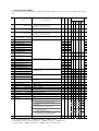
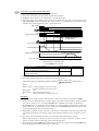
1 Function Code Tables
Change when
running
Data
copying
Listed below are function codes added or modified in the FRENIC-MEGA series of inverters having a ROM version 3600 or
later.
0: Output in voltage (0 to 10 VDC)
F29 Analog Output [FMA]/[FM1]
(Mode selection) 1: Output in current (4 to 20 mA DC)
*1
2: Output in current (0 to 20 mA DC)
Y
Y
0
Y
Y
Y
Y
Y
5
17: Positional deviation in synchronous operation
F31 Analog Output [FMA]/[FM1]
(Function)
*1
Y
Y
0
N
Y
N
Y
N
5
F32 Analog Output [FM2]
0: Output in voltage (0 to 10 VDC)
(Mode selection) 1: Output in current (4 to 20 mA DC)
2: Output in current (0 to 20 mA DC)
Y
Y
0
Y
Y
Y
Y
Y
5
F35 Pulse Output [FMP]
*1 Analog Output [FM2]
Y
Y
0
N
Y
N
Y
N
5
Y
Y
Y
Y
Y
Code
Name
Data setting range
Drive control
Refer
to
Default
PG w/o w/ Torque page:
setting V/f V/f PG PG control
(Function)
E01 Terminal [X1] Function
N
Y
0
E02 Terminal [X2] Function
N
Y
1
5
E03 Terminal [X3] Function
N
Y
2
5
E04 Terminal [X4] Function
N
Y
3
5
E05 Terminal [X5] Function
N
Y
4
5
E06 Terminal [X6] Function
N
Y
5
5
E07 Terminal [X7] Function
N
Y
*3
5
E08 Terminal [X8] Function
*2
N
Y
7
E09 Terminal [X9] Function
*2
N
Y
8
E20 Terminal [Y1] Function
59 (1059): Enable battery operation
(BATRY)
29 (1029): Synchronization completed
(SY)
N
Y
0
E21 Terminal [Y2] Function
N
Y
1
8
E22 Terminal [Y3] Function
N
Y
2
8
E23 Terminal [Y4] Function
N
Y
7
8
E24 Terminal [Y5A/C] Function
N
Y
15
8
N
Y
99
N
Y
0
Y
Y
Y
Y
Y
8
N
Y
0
Y
Y
Y
Y
Y
8
N
Y
0
Y
Y
Y
Y
Y
8
N
Y
98
Y
Y
Y
Y
Y
5
N
Y
99
Y
Y
Y
Y
Y
5
N
Y
0
Y
Y
Y
Y
Y
8
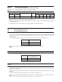
E27 Terminal [30A/B/C] Function
E61 Terminal [12] Extended Function
E62 Terminal [C1] Extended Function
17: Speed limit FWD
18: Speed limit REV
E63 Terminal [V2] Extended Function
E98 Terminal [FWD] Function
59 (1059): Enable battery operation
(BATRY)
E99 Terminal [REV] Function
C40 Terminal [C1] Range Selection
P05 Motor 1
0: 4 to 20 mA
1: 0 to 20 mA
N
Y
N
8
8
Y
Y
0
Y
N
N
N
N
8
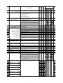
0000 to FFFF (hex.)
Y
Y
0
Y
Y
Y
Y
Y
9
H82 Light Alarm Selection 2
0000 to FFFF (hex.)
Y
Y
0
Y
Y
Y
Y
Y
9
Y
Y
0
Y
N
N
N
N
8
(Online tuning) 0: Disable
1: Enable
Y
H81 Light Alarm Selection 1
A19 Motor 2
(Online tuning) 0: Disable
N
5
1: Enable
b19 Motor 3
(Online tuning) 0: Disable
1: Enable
Y
Y
0
Y
N
N
N
N
8
r19 Motor 4
(Online tuning) 0: Disable
1: Enable
Y
Y
0
Y
N
N
N
N
8
A46 Speed Control 2
I (Integral time) 999: Disable integral action
Y
Y
0.100
N
Y
Y
Y
N
9
b46 Speed Control 3
I (Integral time) 999: Disable integral action
Y
Y
0.100
N
Y
Y
Y
N
9
r46 Speed Control 4
I (Integral time) 999: Disable integral action
Y
Y
0.100
N
Y
Y
Y
N
9
N
Y
0
J96 Brake Signal
0 to 31
(Speed condition selection)
d04 Speed Control 1
9
Bit 0: Criterion speed for brake-ON
(0: Detected speed, 1: Reference speed)
N
N
Y
Y
Bit 1: Reserved.
N
N
N
N
N
Bit 2: Response for brake-OFF current
(0: Slow response, 1: Quick response)
Y
Y
Y
Y
N
Bit 3: Criterion frequency for brake-ON
(0: Stop frequency (F25),
1: Brake-ON frequency (J71))
N
N
Y
Y
N
Bit 4: Output condition of brake signal
(0: Independent of a run command ON/OFF
1: Only when a run command is OFF)
N
N
Y
Y
N
N
Y
Y
Y
N
I (Integral time) 999: Disable integral action
Y
*1 [FM1] and [FM2] for Asia (FRN_ _ _G1-A) and EU (FRN_ _ _G1-E) versions
*2 Terminals [X8] and [X9] not provided on Asia (FRN_ _ _G1-A) or EU (FRN_ _ _G1-E) version
*3 "8" for Asia (FRN_ _ _G1-A) and EU (FRN_ _ _G1-E) versions; "6" for other versions
2
Y
0.100
N
9
Change when
running
Data
copying
d12 Speed Control (Jogging)
999: Disable integral action
I (Integral time)
Y
Y
0.100
N
Y
Y
Y
N
9
d23 PG Error Processing
0:
1:
2:
3:
4:
5:
N
Y
2
N
Y
Y
Y
N
11
d35 Overspeed Detection Level
0 to 120%
999: Depends on setting of d32 or d33
Y
Y
999
N
Y
Y
Y
Y
12
d41 Application-defined Control
0: Disable (Ordinary control)
N
Y
0
13
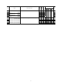
Code
Name
d60 Command
Data setting range
Continue to run 1
Stop running with alarm 1
Stop running with alarm 2
Continue to run 2
Stop running with alarm 3
Stop running with alarm 4
Drive control
Refer
to
Default
PG w/o w/ Torque page:
setting V/f V/f PG PG control
Y
Y
Y
Y
Y
1: Enable (Constant peripheral speed control)
N
Y
N
N
N
2: Enable (Simultaneous synchronization, without Z phase)
N
Y
N
Y
N
3: Enable (Standby synchronization)
N
Y
N
Y
N
4: Enable (Simultaneous synchronization, with Z phase)
N
Y
N
Y
N
0014 to 0E10 (hex.)
(Encoder pulse resolution) (20 to 3600 pulses)
N
Y
0400
(1024)
N
Y
N
Y
N
13
d71 Synchronous Operation
0.00 to 1.50 times
(Main speed regulator gain)
Y
Y
1.00
N
Y
N
Y
N
13
d72
Y
Y
15.00
N
Y
N
Y
N
13
d73
(APR positive output limiter) 20 to 200%, 999: No limiter
(APR P gain) 0.00 to 200.00 times
Y
Y
999
N
Y
N
Y
N
13
d74
(APR negative output limiter) 20 to 200%, 999: No limiter
Y
Y
999
N
Y
N
Y
N
13
Y
Y
1.00
N
Y
N
Y
N
13
d75
(Z phase alignment gain) 0.00 to 10.00 times
d76
(Synchronous offset angle) 0 to 359 degrees
Y
Y
0
N
Y
N
Y
N
13
d77
(Synchronization completion 0 to 100 degrees
detection angle)
Y
Y
15
N
Y
N
Y
N
13
Y
Y
65535
*4
N
Y
N
Y
N
13
d78
(Excessive deviation detection 0 to 65535 (Display in units of 10 pulses)
range) (For 10000 or more: Display of the upper four digits in units
of 100 pulses)
d81 Reserved
0 or 1
Y
Y
1
-
-
-
-
-
-
d82 Magnetic Flux Weakening Control
(Vector control without speed
sensor)
0: Disable
1: Enable
Y
Y
1
N
N
N
N
Y
13
d83 Magnetic Flux Weakening Low
10 to 70%
Limiter (Vector control without speed
sensor)
Y
Y
40%
N
N
N
N
Y
13
-
d84 Reserved
0 to 20 dB
Y
Y
5 dB
-
-
-
-
-
d85 Reserved
0 to 200%
Y
Y
95%
-
-
-
-
-
-
d90 Magnetic Flux Level during
Deceleration (Vector control)
100 to 300%
Y
Y
150%
N
N
Y
Y
N
14
d91 Reserved
0.00 to 2.00, 999
Y
Y
999
-
-
-
-
-
-
d92 Reserved
0.00 to 3.00
Y
Y
0.00
-
-
-
-
-
-
d98 Reserved
0000 to FFFF (hex.)
Y
Y
0000
Y
Y
N
N
N
d99 Function Extension 1
0 to 31
Y
Y
0
Bit 0: Reserved
-
-
-
-
-
Bit 1: Reserved
-
-
-
-
-
Bit 2: Reserved
-
-
-
-
-
Bit 3: JOG (Ready for jogging) via the communications link
(0: Disable, 1: Enable)
Y
Y
Y
Y
N
Bit 4: Reserved
U01 Customizable Logic:
(Input 1) 29 (1029): Synchronization completed
U02 Step 1
(SY)
14
-
-
-
-
-
N
Y
N
Y
N
N
Y
0
(Input 2)
N
Y
0
8
8
U06 Customizable Logic:
(Input 1)
N
Y
0
8
U07 Step 2
(Input 2)
N
Y
0
8
U11 Customizable Logic:
(Input 1)
N
Y
0
8
U12 Step 3
(Input 2)
N
Y
0
8
U16 Customizable Logic:
(Input 1)
N
Y
0
8
U17 Step 4
(Input 2)
N
Y
0
8
U21 Customizable Logic:
(Input 1)
N
Y
0
8
U22 Step 5
(Input 2)
N
Y
0
8
U26 Customizable Logic:
(Input 1)
N
Y
0
8
U27 Step 6
(Input 2)
N
Y
0
8
U31 Customizable Logic:
(Input 1)
N
Y
0
8
U32 Step 7
(Input 2)
N
Y
0
8
*4 The standard keypad displays 6553 on the LED monitor and lights the x10 LED.
3
Change when
running
Data
copying
U36 Customizable Logic:
(Input 1)
N
Y
0
U37 Step 8
(Input 2)
N
Y
0
8
U41 Customizable Logic:
(Input 1)
N
Y
0
8
Code
Name
Data setting range
Drive control
Refer
to
Default
PG w/o w/ Torque page:
setting V/f V/f PG PG control
8
U42 Step 9
(Input 2)
N
Y
0
8
U46 Customizable Logic:
(Input 1)
N
Y
0
8
U47 Step 10
(Input 2)
N
Y
0
N
Y
100
Y
Y
Y
Y
Y
5
U82 Customizable Logic Output Signal 2
N
Y
100
Y
Y
Y
Y
Y
5
U83 Customizable Logic Output Signal 3
N
Y
100
Y
Y
Y
Y
Y
5
U84 Customizable Logic Output Signal 4
N
Y
100
Y
Y
Y
Y
Y
5
U85 Customizable Logic Output Signal 5
N
Y
100
Y
Y
Y
Y
Y
5
U81 Customizable Logic Output Signal 1 59 (1059): Enable battery operation
(Function selection)
4
(BATRY)
8
2 Details of Function Codes Added
F29
Analog output [FMA]/[FM1] (Mode selection) *
F32
Analog output [FM2] (Mode selection) *
* [FM1] and [FM2] are for Asia (FRN_ _ _G1-A) and EU (FRN_ _ _G1-E) versions.
Versions except Asia (FRN_ _ _G1-A) and EU (FRN_ _ _G1-E) versions
Mode selection (F29)
F29 specifies the property of the output to terminal [FMA]. You need to set switch SW4 on the control printed circuit
board (control PCB).
Data for F29
Position of slide switch SW4
mounted on the control PCB
IO
[FMA] output form
Current (0 to +20 mA DC)
2
Asia (FRN_ _ _G1-A) and EU (FRN_ _ _G1-E) versions
Mode selection (F29 and F32)
F29 and F32 specify the property of the output to terminals [FM1] and [FM2], respectively. You need to set the slide
switches on the control printed circuit board (control PCB).
Output form
Current (0 to +20 mA DC)
Terminal [FM1]
Position of slide switch
Data for F29
SW4 on the control PCB
2
IO1
F31
Analog Output [FMA]/[FM1] (Function) *
F35
Pulse Output [FMP] (Function)
Analog Output [FM2] (Function) *
Terminal [FM2]
Position of slide switch
Data for F32
SW6 on the control PCB
2
IO2
* [FM1] and [FM2] are for Asia (FRN_ _ _G1-A) and EU (FRN_ _ _G1-E) versions.
These function codes enable monitoring of deviation in angle in synchronous operation. For details about synchronous
operation, refer to the PG Interface Card Instruction Manual.
Data for F31
[FMA]/[FM1] output
Data for F35
[FMP]/[FM2] output
17
Positional deviation in
synchronous operation
Function
(Monitor the following)
Deviation in angle
Meter scale
(Full scale at 100%)
0% to 50% to 100%,
representing -180° to 0° to +180° of the deviation
E01 to E09
E01 to E07
Terminal [X1] to [X9] Function
Terminal [X1] to [X7] Function *
E98
E99
Terminal [FWD] Function
Terminal [REV] Function
U81 to U85
Customizable Logic Output Signal 1 to 5 (Function selection)
* Terminals [X8] and [X9] are not provided on Asia (FRN_ _ _G1-A) or EU (FRN_ _ _G1-E) version.
Function code data
Active ON Active OFF
59
1059
Terminal commands assigned
Enable battery operation
Symbol
BATRY
Drive control
Related
PG
w/ Torque function codes
V/f V/f w/o
PG PG control
Y
Y
Y
Y
Y
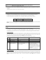
■ Enable battery operation -- BATRY (Function code data = 59)
Turning this terminal command ON cancels the undervoltage protection so that the inverter runs the motor with battery
power under an undervoltage condition.
When BATRY is assigned to any digital input terminal, the inverter trips after recovery from power failure just as F14 =
1 regardless of F14 setting. When BATRY is ON, the main power down detection is disabled regardless of H72 setting.
5
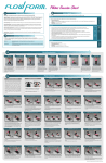
Prerequisites for battery operation
(1) The terminal command BATRY (data = 59) must be assigned to any digital input terminal.
(2) A DC link bus voltage must be supplied from the battery to the main circuit (L1/R-L3/T or L2/S-L3/T) as
shown in Figures A and B given below.
(3) A regulated voltage (sine-wave or DC voltage) must be supplied to the auxiliary power supply (R0-T0).
(4) For 200 V class series of 37 kW or above and 400 V ones of 75 kW or above, a regulated voltage
(sine-wave) must be supplied to the auxiliary fan power supply (R1-T1) as shown in Figure B. The fan
power supply connector must be configured for battery operation as shown in Figure C.
(5) The BATRY-assigned terminal (data = 59) must be turned ON at the same moment as closing of MC2.
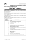
Figure A Connection Diagram
for 200 V Class Series of 30 kW or Below and 400 V Ones of 55 kW or Below
Figure B Connection Diagram
for 200 V Class Series of 37 kW or Above and 400 V Ones of 75 kW or Above
CN R (Red)
CN W (White)
CN W (White)
CN R (Red)
Setting
When not using R1 or T1
Usage (Factory default)
Figure C
When using R1 and T1 (BATRY operation)
Fan Power Supply Switching Connector
6
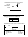
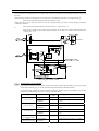
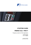
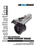
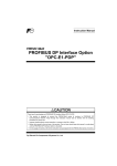
About battery operation (when BATRY is ON)
(1) The undervoltage protective function (lu ) is deactivated.
(2) The inverter can run the motor even under an undervoltage condition.
(3) The RDY ("Inverter ready to run") output signal is forcedly turned OFF.
(4) The bypass circuit of the charging resistor comes to be closed (73X ON) after a delay of time T1 from
when the BATRY is turned ON. Further, after a delay of time T2 (a maximum of 0.1 second), the battery
operation starts. For the specifications of T1, see the table below.
Main power
MC1
ON
ON
BATRY
MC2
73X
Battery power supply
ON
ON
ON
ON
ON
T1
LU
RDY
Battery operationenabled zone
T2
ON
ON
DC link bus voltage Edc
Undervoltage level
Detected speed
Reference Frequency
S-curve acce./dece. disabled
0
Run command
ON
Battery Operation Timing Diagram
T1 from BATRY ON to 73X ON
Power condition
After the control power supply goes OFF, the battery
power and control power are turned ON.
The control power remains ON or after a momentary
power failure happens.
30 kW or below
100 ms
37 kW or above
500 ms
205 ms
(5) The S-curve acceleration/deceleration is disabled.
(6) The battery operation speed can be calculated by the following formula.
Reference speed (pre - ramp) during battery operation ≤
Battery voltage - 5[V ]
× Rated speed × k
2 × Rated voltage
Where,
Battery voltage: 24 VDC or higher for 200 V class series
48 VDC or higher for 400 V class series.
Rated speed :
F04
Rated voltage : F05 (Motor rated voltage (V))
k:
Safety coefficient (Less than 1, about 0.8)
Precautions
(1) The battery power supply must be connected before or at the same moment as turning ON of BATRY.
(2) As shown in the timing diagram above, battery operation is possible within the battery operation-enabled
zone. There is a delay of "T1 + T2" after the BATRY, MC2, and battery power supply are turned ON.
(3) The BATRY must not be turned ON when the voltage level is higher than the specified undervoltage level
(that is, before the lu appears after a power failure). Turning the BATRY ON causes the bypass circuit
(73X) of the charging resistor to stick to ON (closed).
(4) During battery operation, driving with a heavy load must be avoided and the motor must run with no load
or braking load condition. Low battery voltage cannot generate sufficient torque, causing the motor to
stall.
(5) The battery operation must be performed at a low speed. Be careful with the battery capacity.
When a high voltage (e.g., 300 VDC for 200 V class series of inverters or 600 VDC for 400 V ones) is
applied, not battery operation but normal operation must be performed.
(6) In normal operation, the BATRY must be OFF. Turning the main power supply ON with the BATRY being
ON could damage the rectifier diode because the 73X is ON.
7
E20 to E23
E24, E27
Terminal [Y1] to [Y4] Function
Terminal [Y5A/C] and [30A/B/C] Functions (Relay output)
U01, U02 … U46, Customizable Logic: Step 1 to 10 (Input 1, Input 2)
U47
Function code data
Active ON
Active OFF
29
1029
Drive control
Functions assigned
Symbol
Synchronization completed
SY
V/f
PG
V/f
N
Y
w/o PG w/ PG
N
Y
Torque
control
N
■ Synchronization completed -- SY (Function code data = 29)
This output signal comes ON when the control target comes inside the synchronization completion detection angle in
synchronous operation.
For details about synchronous operation, refer to the PG Interface Card Instruction Manual.
E61
Terminal [12] Extended Function
E62
Terminal [C1] Extended Function
E63
Terminal [V2] Extended Function
E61, E62, and E63 define the function of the terminals [12], [C1], and [V2], respectively.
As listed below, under torque control, analog inputs through terminals [12], [C1], and [V2] specify the motor speed
limit values. To limit the motor speed to the maximum frequency (F02, A01, b01, r01), apply a full-scale analog input
(maximum input).
It is recommended that this speed limit function be used together with d35 (Overspeed detection level).
Data for E61,
E62, or E63
Input assigned to
[12], [C1] and [V2]
17
Speed limit FWD
18
Speed limit REV
Function codes C31 to C45 (Analog input adjustment) apply to these analog inputs.
C40
Terminal [C1] Range Selection
C40 specifies the range of the input current signal on terminal [C1] as listed below.
P05, A19
b19, r19
Data for C40
Range of Input Current Signal
on Terminal [C1]
0
1
4 to 20 mA
0 to 20 mA
Motor 1/2/3/4 (Online tuning)
Long run under "Dynamic torque vector control" or "Slip compensation control" causes motor temperature change,
varying the motor parameters. This changes the motor speed compensation amount, resulting in motor speed deviation
from the initial rotating speed.
Enabling online tuning identifies motor parameters covering the motor temperature change to decrease the motor speed
fluctuation.
To perform online tuning enabled with P05/A19/b19/r19, set P04 (Auto-tuning) to "2."
Note: Online tuning can be performed only when F42 = 1 (Dynamic torque vector control) or when F42 = 2
(V/f control with slip compensation active) and F37 = 2 or 5 (Auto torque boost).
8
A46, b46, r46, d04, Speed Control 2, Speed Control 3, Speed Control 4, Speed Control 1,
d12
Speed Control (Jogging) (Integral time)
These function codes are used to configure the Automatic Speed Regulator (ASR) by selecting the PI controller or P
controller.
Setting the function code data to "999" selects the P controller.
H81, H82
Light Alarm Selection 1 and 2
Assigning "1" to bit 2 of H82 defines excessive positioning deviation in synchronous operation as a light alarm.
For details about excessive positioning deviation, refer to the PG Interface Card Instruction Manual.
For details about definition of light alarms, refer to the FRENIC-MEGA Instruction Manual, Chapter 5.
Light Alarm Selection 2 (H82), Bit Assignment of Selectable Factors
Bit
2
Code
Content
ero
Positioning control error
Even if a positioning control error is defined as a light alarm with H82, the error that occurred when the
inverter was servo-locked does not cause a light alarm operation but trips the inverter.
J68 to J72
J95, J96
Brake Signal
These function codes are for the brake releasing/turning-on signals of vertical carrier machines.
It is possible to set the conditions of the brake releasing/turning-on signals (current, frequency or torque) so that a
hoisted load does not fall down at the start or stop of the operation, or so that the load applied to the brake is reduced.
Releasing the Brake
When any of the inverter output current, output frequency, or torque command value exceeds the specified level of the
brake signal (J68/J69/J95) for the period specified by J70 (Brake signal (Brake-OFF timer)), the inverter judges that
required motor torque is generated and turns the signal BRKS ON for releasing the brake.
This prevents a hoisted load from falling down due to an insufficient torque when the brake is released.
Function
code
J68
J69
J70
J95
J96
Name
Data setting range
Brake-OFF current
Brake-OFF frequency/speed
Brake-OFF timer
Brake-OFF torque
Speed condition selection
(Braking conditions)
0% to 300%:
0.0 to 25.0 Hz
0.0 to 5.0 s
0% to 300%
Response for brake-OFF current (Bit 2)
0: Slow response (default)
1: Quick response
Remarks
Available only under V/f control.
Available only under vector control.
Specifies the response type for
brake-OFF current detection.
Selecting slow response inserts a
detection filter into the current detection
circuit so that the brake-OFF timing will
be slightly behind the rising edge of the
actual current.
If the delay is not negligible with
adjustments, select quick response.
Turning the Brake ON
When the run command is OFF and the output frequency drops below the level specified by J71 (Brake signal
(Brake-ON frequency/speed)) and stays below the level for the period specified by J72 (Brake signal (Brake-ON timer)),
the inverter judges that the motor rotation is below a certain level and turns the signal BRKS OFF for activating the
brake.
9
Under vector control, when the reference speed or the detected one drops below the level of the brake-ON frequency
(specified by bit 3 of J96) and stays below the level for the period specified by J72 (Brake signal (Brake-ON timer)), the
inverter judges that the motor rotation is below a certain level and turns the signal BRKS OFF for activating the brake.
This operation reduces the load applied to the brake, extending lifetime of the brake.
Function
code
J71
J72
J96
Name
Data setting range
Remarks
Brake-ON frequency/speed 0.0 to 25.0 Hz
Brake-ON timer
0.0 to 5.0 s
Speed condition selection
Criteria of speed condition for brake-ON
(Braking conditions)
(Bit 0)
(Available only under vector control.)
Specifies the criteria of speed to be used
for brake-ON condition.
0: Detected speed
When "Vector control without speed
1: Reference speed
sensor" is selected, specify "Reference
speed" (Bit 0 = 1).
Criteria of frequency for brake-ON
(Available only under vector control.)
(Bit 3)
Specifies the criteria of frequency to be
used for brake-ON timing.
0: Stop frequency (F25)
If "Detected speed" and "Stop frequency"
1: Brake-ON frequency (J71)
are selected (Bit 0 = 0 and Bit 3 = 0) to
determine brake-ON timing, the brake
may be applied after running at the stop
frequency (F25) due to a speed error.
If it is required that brake is applied
during running at the stop frequency,
select "Brake-ON frequency" (Bit 3 = 1)
as criteria of frequency.
When jogging or inching the motor for
vertical conveyance, use J71 as
brake-ON frequency.
Turn-on condition of brake signal (Bit 4) (Available only under vector control.)
Specifies whether to turn on a brake
0: Independent of a run command
signal independent of a run command
ON/OFF
ON/OFF or only when a run command is
1: Only when a run command is OFF
OFF.
When normal and reverse operations are
switched, brake-ON conditions may be
met in the vicinity of zero speed. For
such a case, select "Only when a run
command is OFF" (Bit 4 = 1).
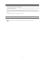
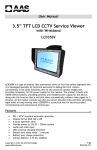
• Operation time chart when Criteria of frequency for brake-ON (Bit 3) = 1 (Brake-ON frequency)
10
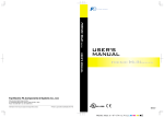
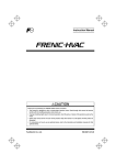
• Operation time chart when Turn-on condition of brake signal (Bit 4) = 1 (Only when a run command is OFF)
F39: Stop frequency
(Holding time)
Reference speed/
Detected speed
J71: Brake-ON frequency/speed**
F25: Stop frequency
ON
Run command
Brake signal
OFF
ON
OFF
J72: Brake-ON timer*
*If the inverter output is shut down during the timer
period specified by J72, the inverter ignores the timer
count and activates the brake.
**When bit 3 of J96 = 1
d23
PG Error Processing
d23 defines the detection condition and error processing to be applied when a PG error occurs.
- Data setting range: d23 = 0, 1, 2, 3, 4, 5
Data for d23
0
1
2
3
4
5
Function
Continue to run 1
Stop running with alarm 1
Stop running with alarm 2
Continue to run 2
Stop running with alarm 3
Stop running with alarm 4
If the speed regulator's deviation (between the reference speed and detected one) is out of the specified range (d21) for
the specified period (d22), the inverter judges it as a PG error.
d23 defines the detection condition (and exception), processing after error detection, and hysteresis width as listed
below.
Data for
d23
Detection condition
(and exception)
0
When the inverter cannot follow
the reference speed (even after
soft-starting) due to a heavy
overload or similar, so that the
detected speed is less than the
reference speed, the inverter does
not interpret this situation as a PG
error.
No exception.
When the inverter cannot follow
the reference speed (even after
soft-starting) due to a heavy
overload or similar, so that the
detected speed is less than the
reference speed, the inverter does
not interpret this situation as a PG
error.
1
2
3
4
5
No exception.
Processing after error detection
Hysteresis width for error detection
The inverter outputs the PG
error detected signal PG-ERR
and continues to run.
The inverter initiates a motor
coast to stop, with the ere
alarm.
It also outputs the PG error
detected signal PG-ERR.
Detection width = d21 × Maximum
frequency, which is constant even if
the speed command is above the
base frequency (F04).
The inverter outputs the PG
error detected signal PG-ERR
and continues to run.
If the speed command is below the
base frequency (F04), detection
width = d21 × Maximum frequency,
which is constant.
If it is above the base frequency,
detection width = d21 × Speed
command × Maximum frequency ÷
Base frequency (F04).
The inverter initiates a motor
coast to stop, with the ere
alarm.
It also outputs the PG error
detected signal PG-ERR.
11
d35
Overspeed Detection Level
d35 specifies the overspeed detection level under torque control by percentage of the maximum frequency (F03, A01,
b01, r01).
If the following condition is satisfied, the inverter detects an overspeed state and issues an overspeed alarm 0s.
Motor speed ≥ Maximum frequency (F03/A01/b01/r01) × d35
Setting d35 data to "999" causes the inverter to issue an overspeed alarm 0s if either of the following conventional
conditions is satisfied.
Motor speed ≥ Maximum frequency (F03/A01/b01/r01) × (d32 or d33) × 1.2
or
Motor speed ≥ 200 Hz (vector control with speed sensor) or 120 Hz (vector control without speed sensor)
× (d32 or d33) × 1.2
Block Diagram of Torque Control
Torque/Torque current command
It is possible to command torque/torque current from an analog voltage input (terminal [12] or [V2]) or analog
current input (terminal [C1]), or via the communications link (function codes S02 and S03).
(To use the analog voltage/current input, function codes E61 (terminal [12]), E62 (terminal [C1]), and E63
(terminal [V2]) should be set to 10 or 11 as shown in the table below.
Function
codes
E61=10
E61=11
Input
Command form
Terminal [12]
(-10 V to 10 V)
Torque command
Torque current
command
Terminal [V2]
(-10 V to 10 V)
Torque command
Torque current
command
Torque command
Torque current
command
E63=10
E63=11
Torque command
-
Motor rated torque / ±100.00%
Torque current
command
-
Motor rated torque current / ±100.00%
Terminal [C1]
(0, 4 to 20 mA)
S02
(-327.68 to 327.67%)
S03
(-327.68 to 327.67%)
E62=10
E62=11
Setting specifications (Factory default)
Motor rated torque ±100% / ±10V
Motor rated torque current ±100% /
±10V
Motor rated torque ±100% / ±10V
Motor rated torque current ±100% /
±10V
Motor rated torque 100% / 20 mA
Motor rated torque current 100% / 20
mA
Function codes C31 to C45 (Analog input adjustment) are applied to these analog inputs.
12
Speed limiter
The response of the speed limiter can be adjusted by using P gain and Integral time of the speed control as
listed below.
Selected Motor
M1
M2
M3
M4
d41
Function Codes
P gain
Integral time
d03
A45
b45
r45
d04
A46
b46
r46
Application-Defined Control
d41 selects/deselects constant peripheral speed control or synchronous operation (simultaneous or standby
synchronization).
Constant peripheral speed control suppresses an increase in peripheral speed (line speed) resulting from the increasing
radius of the take-up roll in a winder system.
Synchronous operation drives two or more shafts of a conveyer while keeping their positions in synchronization. For
details about synchronous control, refer to the PG Interface Card Instruction Manual.
Application-Defined Control (d41)
Data for d41
Function
0
1
Disable (Ordinary control)
Enable (Constant peripheral speed control)
Refer to the FRENIC-MEGA User's Manual, Chapter 5, Section 5.4.8 "d codes (Application
functions 2)."
2
3
4
Enable (Simultaneous synchronization, without Z phase)
Enable (Standby synchronization)
Enable (Simultaneous synchronization, with Z phase)
d60 to d63
Command (Pulse Rate Input)
(Encoder pulse resolution, Filter time constant, Pulse count factor 1, Pulse count factor 2)
d71 to d78
Synchronous Operation
These function codes specify various parameters required for synchronous operation. For details, refer to the PG
Interface Card Instruction Manual.
d82
Magnetic Flux Weakening Control (Vector control without speed sensor)
Setting d82 data to "1" (Enable) controls the motor magnetic flux in accordance with the torque command.
When the torque command value is small, this control weakens the motor magnetic flux to improve the control stability.
d83
Magnetic Flux Weakening Low Limiter (Vector control without speed sensor)
d83 applies to the lower limit of the motor magnetic flux level when d82 = 1 (Enable).
Decreasing the d83 setting too much may cause hunting, speed stagnation, and other problems.
Use the default setting "40%" as long as there is no problem.
13
d90
Magnetic Flux Level during Deceleration (Vector control)
d90 specifies the magnetic flux level to be applied during deceleration under vector control by percentage of the rated
motor magnetic flux (determined by P06/A20/b20/r20).
d90 data takes effect only when H71 = 1 (Deceleration Characteristics enabled) and F42/A14/b14/r14 = 5 or 6 (Vector
control with/without speed sensor).
Increasing the d90 setting can reduce the deceleration time but increases the inverter output current and the motor
temperature rise. In applications repeating frequent start/stop drive, an overload may apply to the inverter or motor.
Adjust the d90 setting so that the inverter output current (RMS equivalent) comes to be smaller than the motor rated
current.
Use the default setting "150%" as long as there is no problem.
d99
Function Extension 1
Setting bit 3 of d99 to "1" enables a JOG ("Ready for jogging") given via the communications link.
Other bits of d99 are reserved for particular manufacturer, so do not change the settings.
14
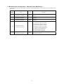
3 Monitoring the running status -- Menu #3 "Drive Monitoring" -Listed below are monitoring items added or modified in the FRENIC-MEGA series of inverters having a ROM version
3000 or later.
LED
monitor
shows:
3_17
3_18
3_19
Item
Target position pulse
(synchronous operation)
Current position pulse
(synchronous operation)
Current deviation pulse
(synchronous operation)
Unit
Description
Shows the target position pulse for synchronous
operation.
Shows the current position pulse for synchronous
operation.
Pulse
Pulse
Shows the current deviation pulse for synchronous
operation.
Pulse
Shows the current control status.
0: Synchronous operation disabled
20: Synchronous operation canceled
21: Synchronous operation stopped
22: Waiting for detection of Z phase
23: Z phase of reference PG detected
24: Z phase of slave PG detected
25: Synchronization in progress
26: Synchronization completed
3_20
Control status monitor
(synchronous operation)
--
3_26
Positioning deviation
(synchronous operation)
degree
15
Shows the positioning deviation (in degree) for
synchronous operation.
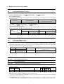
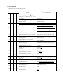
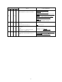
4 List of Errata
The table below provides a list of errata for the FRENIC-MEGA Instruction Manuals (INR-SI47-1183b-E, INR-SI47-1223c
-E, INR-SI47-1334-E, and INR-SI47-1335a-E).
Page
Wrong
1183b 1223c 1334 1335a
vii
ix
-
-
v
vi
-
Correct (underlined)
Fuse rating column (IEC number):
(FRN3.7G1■-2□/FRN3.7G1■-4□ or lower
models)
IEC60269-1
IEC60269-2
Current rating in the fuse rating column:
(FRN55G1■-4□)
400 (IEC60269-4)
350 (IEC60269-4)
Standard in item 9: EN60204 Appendix C.
IEC60364-5-52
Note to be added.
In a power supply system (I-T NET) where a
neutral point is not grounded, the control
terminals are provided with basic insulation from
the mains. If a person may touch them directly,
an external insulation circuit should be added for
double insulation.
-
Grounding terminal can accept one wire only.
3-15
-
3-12
-
I/O Check Item, 4_15, 4_17
Shows the pulse rate (p/s) of the A/B phase
signal…
5-7
-
5-7
-
Drive control of E31,E32
Torque control: N
Torque control: Y
0.00 to 400.00%
Shows the pulse rate of the A/B phase signal…
(e.g., 1000 p/s is expressed as 1.00.)
5-10
-
5-9
-
C32, C37, C42
Data setting range: 0.00 to 200.00%
-
-
5-10
-
P56
Default setting: 85%
85% (90% for inverters of 132 kW or above)
H13
Data setting range: 0.1 to 10.0 s
0.1 to 20.0 s
Drive control of H15
w/o PG: Y
w/ PG: Y
w/o PG: N
w/ PG: N
5-12
-
5-11
-
5-12
-
5-11,
5-100
-
H46
Data setting range: 0.1 to 10.0 s
0.1 to 20.0 s
5-14
-
5-12,
5-109
-
H80
Data setting range: 0.00 to 0.40
Drive control: Torque Control :Y
0.00 to 1.00
Torque Control : N
5-14
-
5-12
-
Drive control of H92, H93
w/o PG: Y
w/ PG: Y
w/o PG: N
w/ PG: N
5-16,
5-18,
5-20
-
5-14,
5-16,
5-18
-
A56, b56, r56
Default setting: 85%
85% (90% for inverters of 132 kW or above)
5-22
5-22
-
5-22
5-19
5-19
-
5-19
d55
Data setting range: 0, 1
d55
Default setting: 0
0000
d68
Default setting: 40
4.0
0000 to 00FF (in hex.)
16
Page
1183b 1223c 1334 1335a
Wrong
Correct (underlined)
H81, H82: Light Alarm Selection 1 and 2
"PID feedback wire break" to be added.
5-85,
5-87
-
5-110,
5-111
-
5-92
-
5-117
-
Table 5.5 Function Codes to be Switched
Last line
Reserved: d57 A57, b57, r57
-
J62 PID Control (PID control block
selection)
Table
When J62 = 0, 1: Absolute value (Hz)
When J62 = 2,3: Ratio (%)
-
-
5-127
8-2
-
-
to
8-4
-
Addition of Light Alarm Factor
Code: cof
Name: PID feedback wire break
Description: The PID feedback signal wire(s) is
broken.
Table 5.2 Light Alarm Selection 2 (H82),
Bit Assignment of Selectable Factors
Bit: 3
Code: cof
Content: PID feedback wire break
Noncompliance note to be added to
"Applicable safety standards C22.2 No.
14."
17
P57, A57, b57, r57
When J62 = 0, 1: Ratio (%)
When J62 = 2,3: Absolute value (Hz)
The following inverters are not compliant with
C22.2 No. 14.
FRN160G1■-4□ to FRN220G1■-4□
FRN355G1■-4□, FRN400G1■-4□
5 Note
Difference of notation between standard keypad and remote keypad
Descriptions in this manual are based on the standard keypad having a four-digit, 7-segment LED monitor (shown in the
original FRENIC-MEGA Instruction Manuals, Chapter 3). The FRENIC-MEGA also provides a multi-function keypad as an
option, which has an LCD monitor and a five-digit, 7-segment LED, but has no USB port.
If the standard keypad is replaced with an optional multi-function keypad, the display notation differs as shown below.
Function
code
Name
H42
Capacitance of DC Link Bus Capacitor
H44
Startup Counter for Motor 1
H47
Initial Capacitance of DC Link Bus Capacitor
H79
Preset Startup Count for Maintenance (M1)
A52
Startup Counter for Motor 2
b52
Startup Counter for Motor 3
r52
Startup Counter for Motor 4
Standard keypad
d15
Feedback Input (Encoder pulse resolution)
d60
Command (Pulse Rate Input) (Encoder pulse resolution)
H43
Cumulative Run Time of Cooling Fan
H48
Cumulative Run Time of Capacitors on Printed Circuit
Boards
H77
Service Life of DC Link Bus Capacitor (Remaining
time)
H78
Maintenance Interval (M1)
H94
Cumulative Motor Run Time 1
A51
Cumulative Motor Run Time 2
b51
Cumulative Motor Run Time 3
r51
Cumulative Motor Run Time 4
d78
Synchronous Operation (Excessive deviation detection
range)
Hexadecimal notation
Decimal notation
Display in units of 10
hours
Display by hours
Display in units of 10
pulses.
(For 10000 pulses or
more: Display in units
of 100 pulses, with the
x10 LED ON)
18
Multi-function keypad (TP-G1-J1)
Display in units of 10 pulses
High Performance, Multifunction Inverter
Supplement to Instruction Manual
First Edition, November 2010
Fuji Electric Systems Co., Ltd.
The purpose of this instruction manual is to provide accurate information in handling, setting up and operating of the
FRENIC-MEGA series of inverters. Please feel free to send your comments regarding any errors or omissions you may have
found, or any suggestions you may have for generally improving the manual.
In no event will Fuji Electric Systems Co., Ltd. be liable for any direct or indirect damages resulting from the application of
the information in this manual.