1
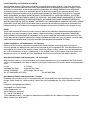
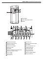
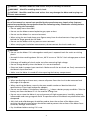
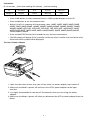
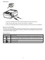
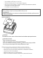
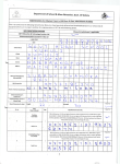
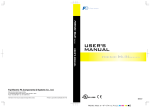
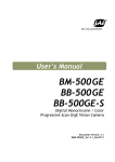
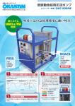
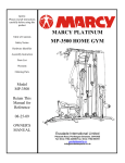
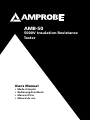
AMB-50
5000V Insulation Resistance
Tester
Users Manual
•
•
•
•
Mode d’emploi
Bedienungshandbuch
Manual d’Uso
Manual de uso
AMB-50
5000V Insulation Resistance Tester
English
Users Manual
June 2010 , Rev.1
©2010 Amprobe Test Tools.
All rights reserved. Printed in China
Limited Warranty and Limitation of Liability
Your Amprobe product will be free from defects in material and workmanship for 1 year from the date of
purchase. This warranty does not cover fuses, disposable batteries or damage from accident, neglect, misuse,
alteration, contamination, or abnormal conditions of operation or handling. Resellers are not authorized
to extend any other warranty on Amprobe’s behalf. To obtain service during the warranty period, return
the product with proof of purchase to an authorized Amprobe Test Tools Service Center or to an Amprobe
dealer or distributor. See Repair Section for details. THIS WARRANTY IS YOUR ONLY REMEDY. ALL OTHER
WARRANTIES - WHETHER EXPRESS, IMPLIED OR STAUTORY - INCLUDING IMPLIED WARRANTIES OF FITNESS
FOR A PARTICULAR PURPOSE OR MERCHANTABILITY, ARE HEREBY DISCLAIMED. MANUFACTURER SHALL
NOT BE LIABLE FOR ANY SPECIAL, INDIRECT, INCIDENTAL OR CONSEQUENTIAL DAMAGES OR LOSSES, ARISING
FROM ANY CAUSE OR THEORY. Since some states or countries do not allow the exclusion or limitation of an
implied warranty or of incidental or consequential damages, this limitation of liability may not apply to you.
Repair
All test tools returned for warranty or non-warranty repair or for calibration should be accompanied by the
following: your name, company’s name, address, telephone number, and proof of purchase. Additionally,
please include a brief description of the problem or the service requested and include the test leads with the
meter. Non-warranty repair or replacement charges should be remitted in the form of a check, a money order,
credit card with expiration date, or a purchase order made payable to Amprobe® Test Tools.
In-Warranty Repairs and Replacement – All Countries
Please read the warranty statement and check your battery before requesting repair. During the
warranty period any defective test tool can be returned to your Amprobe® Test Tools distributor for an
exchange for the same or like product. Please check the “Where to Buy” section on www.amprobe.com
for a list of distributors near you. Additionally, in the United States and Canada In-Warranty repair and
replacement units can also be sent to a Amprobe® Test Tools Service Center (see address below).
Non-Warranty Repairs and Replacement – US and Canada
Non-warranty repairs in the United States and Canada should be sent to a Amprobe® Test Tools Service
Center. Call Amprobe® Test Tools or inquire at your point of purchase for current repair and replacement
rates.
In USA In Canada
Amprobe Test Tools Amprobe Test Tools
Everett, WA 98203 Mississauga, ON L4Z 1X9
Tel: 877-AMPROBE (267-7623) Tel: 905-890-7600
Non-Warranty Repairs and Replacement – Europe
European non-warranty units can be replaced by your Amprobe® Test Tools distributor for a nominalv
charge. Please check the “Where to Buy” section on www.amprobe.com for a list of distributors near
you.
European Correspondence Address*
Amprobe® Test Tools Europe
In den Engematten 14
79286 Glottertal, Germany
Tel.: +49 (0) 7684 8009 - 0
*(Correspondence only – no repair or replacement available from this address. European customers
please contact your distributor.)
AMB-50 5000V Insulation Resistance Tester
21
20
19
18
1
17
2
16
3
15
4
14
13
5
6
Green
Black
Red
12
7
8
9
10
1 LCD
2
Scroll Button
3 Emergency Stop
4 Data Clear the Display Backlight Button
5
Down Button
6 On/Off Button
7 Compare Button
8 Insulation Resistance Button
9 DC Voltages measurement Button
10 Timer Button.
11 AC Voltages measurement Button
11
17
Up Button
18 LINE: High Voltage output input terminal
(two plugs red test lead to one alligator clip)
19 High voltage line shielding input terminal
(two plugs red test lead to one alligator clip)
20 GUARD: Grounding protection input terminal
(one plug black test lead to one alligator clip)
21 EARTH: High resistance measurement input
terminal (one plug green test lead to one
alligator clip)
22 Testing leads:
12 Test Button
Two plugs red test lead to one alligator clip.
13 USB Button
One plug black test lead to one alligator clip.
14 Data Store Button.
One plug green test lead to one alligator
15 Data Recall Button
clip.
16
Scroll Button
AMB-50 5000V Insulation Resistance Tester
3
2
1
1 Safety Shutter
2 Power adaptor Input Terminal
3 USB Port
3
8
16
2
1
16
9
17
10
21
18
20
4
14
7
19
5
6
11
12
13
1 Indicator for DC voltage
12 Data recall is on
2 Indicator for data store full
13 Indicator for polarization index
3 Indicator for clearing
14 Unit symbols
4 Indicator for AC voltage
15 The continuity buzzer is on
5 Indicator for timer
16 Compare feature pass
6 Step symbol
17 Analogue bar graph
7 Indicates selected pass/fail compare value
18 Risk of electric shock
8 Indicates for negative reading
19 Compare feature fail
9 Timer 1 symbol
20 Indicator for power adaptor
10 Timer 2 symbol
21 Battery life indicator
11 Data store is on
CONTENTS
SYMBOLS AND WARNINGS......................................................................................................................2
Symbols..................................................................................................................................................2
UNPACKING AND INSPECTION.................................................................................................................2
INTRODUCTION.........................................................................................................................................2
SAFETY INFORMATION.............................................................................................................................3
OPERATION................................................................................................................................................4
Key Functions.........................................................................................................................................4
MEASUREMENT OPERATION....................................................................................................................5
A.Measuring Voltages...........................................................................................................................5
B.Measuring Insulation Resistance.......................................................................................................6
Information............................................................................................................................................7
The Use of Power Adaptor....................................................................................................................8
USB Interface.........................................................................................................................................8
Battery Saver (Sleep Mode)...................................................................................................................9
Battery Indication..................................................................................................................................9
SPECIFICATIONS.........................................................................................................................................9
PHYSICAL SPECIFICATIONS.......................................................................................................................9
General Specifications...........................................................................................................................9
Feature Summary...................................................................................................................................10
Detailed Accuracy Specifications..........................................................................................................10
MAINTENANCE AND REPAIR....................................................................................................................11
Replacing the Battery............................................................................................................................12
1
SYMBOLS AND WARNINGS
SYMBOLS
N
Battery
�
Refer to the manual
T
Double Insulated
X
Dangerous Voltage
B
Alternating Current
J
Earth Ground
F
Direct Current
I
Symbol
,
Application around and removal
from hazardous live conductors is
permitted
�
Complies with EU directives
=
Do not dispose of this product as
unsorted municipal waste
�
Conform to relevant Australian
standards
Unpacking and Inspection
Your shipping carton should include:
1 AMB-50 Insulation Resistance Tester
1 Test Leads (1 set)
1 Test Probe (1 set)
1 Plug type test Lead with Alligator clip (Green)
1 Plug type test Lead with Alligator clip (Black)
1 Two Plugs type test lead with Alligator clip (Red)
8 Batteries (1.5V, LR14)
1 Users Manual
1 Tool Box
1 Software
1 USB Cable
1 Power adaptor
If any of the items are damaged or missing, return the complete package to the place of purchase
for an exchange.
INTRODUCTION
AMPROBE,AMB-50 insulation resistance tester is a handheld instrument designed primarily to make
resistance/ insulation resistance measurement.
SAFETY INFORMATION
This Meter complies with the standards IEC61010 safety measurement requirement: in pollution
degree 2, overvoltage category (CAT. III 600V) and double insulation.
CAT II: Local level, appliance, PORTABLE EQUIPMENT etc., with smaller transient voltage
overvoltages than CAT. III
Use the Meter only as specified in this operating manual, otherwise the protection provided by the
Meter may be impaired.
2
�DANGER! - identifies conditions and actions that pose hazard(s) to the user
�WARNING! - identifies avoiding electric shock.
�CAUTION! - identifies conditions and actions that may damage the Meter and carrying out
accurate measurement.
�DANGER!
Use of instrument in a manual not specifed by the manufactuer may impair safety features/
protection provided by the equipment. Read the following safety information carefully before
using or servicing the instrument.
• Do not apply more than 600V.
• Do not use the Meter around explosive gas,vapor or dust.
• Do not use the Meter in a wet environment.
• When using the test leads, keep your figures away from the lead contacts. Keep your figures
behind the finger guards on the leads.
• Do not use the Meter with any parts or cover removed.
• When carrying out insulation measurement, do not contact the circuit under test.
�WARNING!
• Do not use the Meter if it is damaged or metal part is exposed. Look for cracks or missing
plastic.
• Be careful when working above 33V rms, 46.7V ac rms or 70V DC. Such voltages pose a shock
hazard.
• Discharge all loading of circuit under test after measuring high voltage.
• Do not change battery when the Meter is in wet environment.
• Place test leads in proper input terminals. Make sure all the test leads are firmly connected to
the Meterís input terminals.
• Make sure the Meter is turned off when opening the battery compartment.
�CAUTION!
• When performing resistance tests, remove all power from the circuit to be measured and
discharge all the power.
• When servicing the Meter, use only the same model number or identical electrical
specifications of test leads and power adaptor.
• Do not use the Meter if the battery indicator ( ) shows a battery empty condition. Take the
battery out from the Meter if it is not used for a long time.
• Do not use or store the Meter in an environment of high temperature, humidity, explosive,
inflammable and strong magnetic field. The performance of the Meter may deteriorate after
dampened.
• Soft cloth and mild detergent should be used to clean the surface of the Meter when
servicing. No abrasive and solvent should be used to prevent the surface of the Meter from
corrosion, damage and accident.
• Dry the Meter before storing if it is wet
3
Operation
Key Functions
ON/OFF
E-STOP
CLEAR /
SAVE
Turn on or off the Meter. Press and hold the button for 1 second to turn the Meter on. Press
again to turn off the Meter.
The Meter default range is 500V insulation resistance continuous measurement when turning
on.
Emergency stop button. Press this button when the Meter is hang and cannot turn off the
power.
Press to turn on or off the display backlight
Press and hold to clear the stored data
Press to store the current measurement value. The maximum number of stored reading is 18.
When the stored readings memory is full, the Meter shows FULL and stop storing. Press and
hold CLEAR / to clear the stored value in order to store the next measurement
value.
• Press once to recall the first stored value.
LOAD
• Press again to exit Load feature.
• Load feature can only be used when there is no high voltage output.
• When the insulation resistance measurement has no testing voltage output, press to select
one voltage range up.
• Under load mode: press to recall the previous stored value.
• When the insulation resistance measurement has no testing voltage output, press to select
one voltage range down.
• Under load mode: press to recall the next stored value.
• When set the timer duration for the measurement of insulation resistance or polarization
index, press to decrement the time. The maximum length of time is 15 minutes and 30
seconds, the Meter will automatically carry out measurement.
• When compare feature measuring insulation resistance, press to decrement a resistance
comparing value.
• After polarization index measurement, press to display polarization index, TIME 2 insulation
resistance value and TIME 1 insulation resistance value in sequence.
• When set the timer duration for the measurement of insulation resistance or polarization
index, press to increment the time. The maximum length of time is 30 minutes and 30
seconds, the Meter will automatically carry out measurement.
• When use the compare feature measuring insulation resistance, press to increment a
resistance comparing value.
• After polarization index measurement, press to display polarization index, TIME 2 insulation
resistance value and TIME 1 insulation resistance value in sequence.
USB
• Press once to start the data transferring to the computer via USB, USB symbol shows on the
display.
• Press again to stop the data transferring to the computer via USB, USB symbol disappears.
COMP
Set a pass / fail limit for insulation tests. The default value is 10M
TIME
Pres to step through continuous measurement, timed measurement and polarization index
measurement in sequence.
TEST
Press to stop or start an insulation resistance test
IR
Press to initiate insulation resistance measurement
DCV
Press to initiate DC voltage measurement
ACV
Pres to initiate AC voltage measurement
4
MEASUREMENT OPERATION
Below section explains how to make measurements.
Press and hold ON/OFF to turn on the Meter, press again to turn off the Meter. The Meter default
range is 500V insulation resistance continuous measurement when turning on.
A.Measuring Voltages
Red
Green
V
CO M
�OPERATING CAUTION!
• To avoid harms to you or damages to the Meter, please do not attempt to measure voltages
higher than 600V or 600V rms, although readings may be obtained.
• Special care should be taken when measuring high voltage.
To measure voltages, set up the Meter as Figure 4 and do the following:
1. Press DCV or ACV button to select DC voltage or AC voltage measurement
2. Insert the red and green test lead into the tested circuit.
3. When measuring DC voltage, if the red test lead is negative voltage, ì-ì symbol will show on
the display.
Note
• When voltage measurement has been completed, disconnect the connection between the
testing leads
and the circuit under test and remove testing leads away from the input terminals of the
Meter.
5
B.Measuring Insulation Resistance
Red
Green
Black
�OPERATING CAUTION!
• When performing insulation resistance tests, remove all power from the circuit to be
measured and discharge all the power.
• Operating the Meter must be very careful as it outputs dangerous voltage during
measurement. Must
make sure the tested object is firmed clipped, hands are away from the clips, then press TEST
button
to put high voltage.
• Do not short circuit the testing leads during high voltages output or test insulation resistance
after high voltages output. This kind of incorrect operating may cause sparking and fire,
which damages the Meter and harms to you.
• Do not measure over 10 seconds when:
500V measure resistance lower than 2Me
1000V measure resistance lower than 5Me
2500V measure resistance lower than 10Me
5000V measure resistance lower than 20Me
To measure insulation resistance, set up the Meter as Figure 5 and do the following:
1. Press IR button to select insulation resistance measurement.
2. When there is no testing voltage output, press
1000V, 2500V or 5000V.
and
button to select voltages of 500V,
3. When performing insulation resistance tests, remove all power from the circuit to be
measured and discharged all the power.
6
4. Insert the red test lead into the LINE input terminal and the black test lead into GUARD
input terminal.
5. Connect the red and black alligator clip to the circuit to be measured, negative voltage
output from LINE terminal.
6. Choose below insulation resistance measurement mode.
a) Continuous Measurement
• Press TIME button to select continuous measurement mode, there is no timer icon on the
LCD.
• Press and hold TEST button for 1 second to carry out continuous measurement. Output
insulation resistance testing voltage, TEST button light up, blinks on every 0.5 seconds.
• Press TEST button to close the insulation resistance measurement voltage when
measurement is completed. TEST button lights off, disappears. The LCD shows the current
insulation resistance measurement value.
b) Timed Measurement
• Press TIME button to select timed measurement mode, the LCD displays TIME 1 and
symbols.
• Press and buttons to set the time (00:10~15:00). Within 1 minute, the time increment
or decrement by every 5 seconds. Afterward, the time increment or decrement by every 30
seconds.
• Then press and hold TEST button for 2 second to carry out timed measurement. TIME 1 and
are displayed and blinked on the LCD on every 0.5 seconds.
• When the set time is reached, the insulation resistance measurement voltage will be
closed and the measurement will be automatically stopped. The LCD displays the insulation
resistance reading.
c) Polarization Index (PI) Measurement
• Press TIME button to select timed measurement mode, the LCD displays TIME 1 and
symbols.
• Press and buttons to set the time (00:10~15:00). Within 1 minute, the time increment
or decrement by every 5 seconds. Afterward, the time increment or decrement by every 30
seconds.
• Press TIME button again. TIME 2, PI and
symbols appear on the LCD.
• Press and buttons to set the time (00:15~15:30). Within 1 minute, the time increment
or decrement by every 10 seconds. Afterward, the time increment or decrement by every 30
seconds.
• Then press and hold TEST button for 2 seconds to carry out timed measurement.
• TIME 1 and are displayed and blinked on the LCD on every 0.5 seconds before TIME 1 set
time is reached.
• TIME 2 and are displayed and blinked on the LCD on every 0.5 seconds before TIME 2 set
time is reached.
• When the two set time are reached, the insulation resistance measurement voltage
will be closed and he measurement will be automatically stopped. The LCD displays the
polarization index reading.
• Press
,
to set through the polarization index, TIME 2 insulation resistance reading and
TIME 2 insulation resistance reading
7
Information
PI = 3 minutes ~10 minutes reading / 30 seconds ~1minute reading
PI
4 or more
4~2
2.0~1.0
1.0 or less
Standard
The best
Good
Warning
Bad
d) Compare Function
• Press COMP button to select compare feature. COMP symbol displays on the LCD..
• Press and buttons to set the compare value
• Below is the list in sequence of the compare value: 10Me, 20Me, 30Me, 40Me, 50Me,
60Me, 70Me, 80Me, 90Me ,100Me, 200Me, 300Me, 400Me, 500Me, 600Me, 700Me,
800Me, 900Me,1Ge, 2Ge, 3Ge, 4Ge, 5Ge, 6Ge, 7Ge, 8Ge, 9Ge, 10Ge,20Ge, 330Ge,
40Ge, 50Ge, 60Ge, 70Ge, 80Ge, 90Ge, 100Ge,200Ge, 300Ge, 400Ge,500Ge, 600Ge,
700Ge, 800Ge, 900Ge
• Press and hold TEST button for 2 seconds to carry out the measurement.
• The NG symbol will display if the insulation resistance value is smaller than resistance value.
Otherwise GOOD symbol will be displayed.
The Use of Power Adaptor
1. Open the side safey shutter, then you will see there is a power adaptor input terminal.
2. Make sure the Meter is power off and insert the UT513 power adaptor to the input
terminal.
3. It is highly recommeded to take out all the batteries when you are using the power
adaptor.
4. Make sure the Meter is power off when you disconnect the UT513 power adaptor from the
Meter.
8
USB Interface
1. Install the included software, the installation guide can be seen from the CD.
2. Open the side safety shutter, then you will see there is a USB port.
3. Insert the included USB cable to the Meterís USB port and the other end to the computer.
Battery Saver (Sleep Mode)
The Meter enters the Sleep Mode and blanks the display if there is no button press for 15 minutes.
This is done to conserve battery power. The Meter comes out of Sleep Mode when ON/OFF button
is pressed and hold for 1 second.
Battery Indication
Battery Indicator
Battery Voltage
10V or less. The battery is empty, don’t use the Meter as it cannot guarantee accuracy.
10V~10.5V. The battery is nearly empty, replacing battery is necessary. At this status, the
Meter can still do 500V and 1000V output measurement, accuracy will not be affected.
10.6V~11.5V :Good
11.6V or more :Full
9
SPECIFICATIONS
Safety and Compliances
Certification
�
Compliances
IEC 61010 CAT.III 600V overvoltage and double insulation standard
Physical Specifications
Display (LCD)
Digital: 1999 counts
Analog bar graph.
Operating Temperature
0°C~40°C (32°F ~104°F )
Storage Temperature
-20°C ~60°C (-4 °F~152°F )
85% @ -10°C ~40°C below;
90% @ 0°C ~40°C :
Relative Humidity
Battery Type
8pcs X 1.5V (LR14) batteries or power adaptor (input voltage 230V, 50/60Hz,
75mA, input DC14V, 1.0A).
Power adaptor is not included
Dimensions (H x W x L)
202 x 155 x 94 mm
Weight
Approx. 2kg (4.4 Lbs) (including battery)
General Specifications
Range
Auto
Overloading
Display OL on insulation resistance range
Battery Indicator
Display
Icon Display
Equips with function and battery indicator icons.
Current Consumption
Maximum: around 1.0A
Average: around 20mA
Feature Summary
Display Backlight
Bright backlight for clear readings in poorly lighted areas.
Computer connection
Via USB interface.
Data Logging and Recall
18
Autorange
The Meter automatically selects best range
Warning
and red light will on.
Voltage
Auto release voltage
COMP Measurement
Use the Compare function to set a pass/fail compare level for the insulation
measurements.
PI Measurement
Polarization Index is the ratio of insulation resistance. You can pre-set two point
of times and automatically carry out the measurement.
TIME
To carry out measurement by setting a specified time within 15 minutes.
10
Detailed Accuracy Specifications
Accuracy: ±([a% of reading] + [number of least significant digits]), guarantee for 1 year.
Operating temperature: 18°C ~28°C
Relative humidity: 45~75%RH
A. Voltage Measurement
Measurement Range
DC Voltage
AC Voltage
±30 ~ ±600V
30V~600V (50/60Hz)
Resolution
1V
Accuracy
±(2%+5) Among them 30~100V(50/60Hz)±(2%+8)
B. Nsulation Resistance Measurement
Output
Voltage
500V
1000V
2500V
5000V
Display
Range
0.5Me ~20Ge
2M e~40Ge
5Me ~100Ge
100Me ~1000Ge
DC 500V 0%~+ 20%
DC1000V 0%~+ 20%
DC 2500V 0%~+ 20%
DC5000V 0%~+ 20%
Open Circuit
Voltage
Test Current
Accuracy
1mA~1.2mA @ 500ke
1mA~1.2mA @ 1Me
0.50M ~99.9M : ±(3%+5)
2.0M ~99.9M : ±(3%+5)
5.0M ~99.9M : ±(3%+5)
100M ~9.99G : ±(5%+5)
100M ~9.99G : ±(5%+5)
100M ~9.99G : ±(5%+5)
10.0G ~20.0G : ±(10%+5)
10.0G ~40.0G : ±(10%+5)
10.0G ~100G : ±(10%+5)
1mA~1.2mA @ 2.5Me
1mA~1.2mA @ 5Me
10.0M ~29.9M : (For
reference only)
30.0M ~99.9M : ±(3%+5)
100M ~9.99G : ±(5%+5)
10.0G ~99.9G : ±(10%+5)
Above 100G : [ ±(20%+5)
Humidity:Below 50%]
Short Circuit
Less than 2.0mA
�OPERATING CAUTION
At any output voltage, when the tested resistance is les than 10M , the testing time cannot
exceed 10 seconds continuously.
MAINTENANCE AND REPAIR
If there appears to be a malfunction during the operation of the meter, the following steps should
be performed in order to isolate the cause of the problem.
1. Check the battery. Replace the battery immediately when the symbol “N” appears on the
LCD.
2. Review the operating instructions for possible mistakes in operating procedure.
Except for the replacement of the battery, repair of the meter should be performed only by a
Factory Authorized Service Center or by other qualified instrument service personnel. The front
panel and case can be cleaned with a mild solution of detergent and water.Apply sparingly with a
soft cloth and allow to dry completely before using. Do not use aromatic hydrocarbons, Gasoline or
chlorinated solvents for cleaning.
• Periodically wipe the case with a damp cloth and mild detergent. Do not use abrasives or
solvents.
• To clean the terminals with cotton bar with detergent, as dirt or moisture in the terminals
can affect readings.
11
• Turn the Meter to OFF when it is not in use.
• Take out the battery when it is not using for a long time.
• Do not use or store the Meter in a place of humidity, high temperature, explosive,
inflammable and strong magnetic field.
• If the Meter is wet, dry it before use.
�WARNING!
• Do not attempt to repair or service your Meter unless you are
qualified to do
• Bring this line up.This is one sentenceso and have the relevant calibration, performance test, and service information.
Replacing the Battery
�WARNING!
To Avoid Electric shock, remove all the test leads from the Meter replacing the batteries.
�OPERATING CAUTION!
• Don’t mix old and new batteries.
• Make sure the polarity is correct when installing batteries.
• Do not use the Meter if the battery indicator (
) shows a battery empty condition
• Do not carry out measuring with the battery compartment is open.
Follow the shown picture and proceed as follows to replace the battery:
• Turn the Meter to OFF and remove all connections from the terminals.
• Remove the screw from the battery compartment, and separate the battery
• compartment from the case bottom.
• Replace with 6pcs of new 1.5V (LR14) batteries.
• Rejoin the case bottom and battery compartment, and reinstall the screw.
12