1
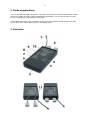
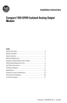
1
User Manual
Galaxis Showtechnik
PYROTEC
PFE Profi Midi 1 Output
Firmware V1.3
Revision Date: January 29th 2010
Galaxis Showtechnik GmbH
Emmertinger Str. 2
84524 Neuötting - Germany
Tel.: +49 / 8671 / 73411
Fax: +49 / 8671 / 73513
www.galaxis-showtechnik.de
[email protected]
Note: Please read the respective user manuals of the controller PFC Advanced and the transmitter
PFS Profi regarding the operation of these devices.
2
3
Table of contents:
1. Safety regulations
2. Fields of applications
3. Illustration
4. Description of indicators and control elements
5. Compatibility
6. Insertion of batteries, power supply, operation time
7. Operation, switching on and receiving mode
8. Displaying the battery status
9. Operation time and battery monitoring
10. Teach-In of the device to a controller PFC Advanced or
PFS Profi
11. Programming of a firing channel
12. Radio range
13. Radio range test
14. Establishing the connecting between the output and the
e-matches, quick-fastening clamps
15. Continuity test (OK test)
16. Firing, firing parameters and firing power
17. Switching off
18. Notes regarding the housing and the protection against
humidity and moisture.
19. Cleaning and Maintenance
20. Warranty
21. Damages caused by misusage, maloperation, malfunction
22. Quick reference, the most important facts on a single
sheet
23. Technical data
Page
4
8
8
9
9
10
10
10
11
11
12
12
13
13
14
14
15
15
15
16
16
17
18
4
1. Safety regulations
Date: Sept. 19th 2007
Safety regulations for the
shells by using e-matches:
firing
of
pyrotechnical
effects
and
aerial
The following instructions are for your understanding about important and
basic safety principles.
Our general safety requirements are based on our own experience plus the
contact and feedback from our customers. These rules allow the safe and
successful usage of all components of our wireless firing systems. With
proceeding development of our products, we will continuously revise and
adapt the safety standards in conclusion with your notifications and
support.
The following safety regulations are part of all our operation manuals
within our product range. These regulations are also available in printed
form and can be downloaded via our internet homepage at any time. Please
forward these instructions to any relevant persons in your company dealing
with this topic.
Any technical device can potentially cause a fault. This could be
encouraged through: wrong usage, unit damage, unit aging as well as the
wear and tear of the unit. This fundamental thesis was the basic principle
when writing these instructions.
1. Smoking or open fire is strictly prohibited within the safety zone!
2. Depending on the type, size and quantity of the pyrotechnical effects
that are being used and depending on the local conditions, allocate the
necessary fire prevention and first aid measurements.
3. In all cases respect and follow any national and technical regulations
as well as the operation manuals respective to the pyrotechnical effects in
use.
4. Make sure that non authorized persons are not within the vicinity of the
pyrotechnical effects and to the respective firing system.
5. The safety boundary distances required by the manufacturer and
authorities are to be respected. Secure the area so that non authorized
persons cannot gain access to the same.
6. The operation manuals and safety instructions of the pyrotechnical
manufacturers must be observed at all times. If in doubt these must be
discussed with the relevant safety organisations.
7. The usage of pyrotechnical effects as well as the respective firing
systems are only allowed to be used according to it's defined function.
8. The components of our firing system are to be covered or encased against
burn-off cinders or weather conditions where necessary. Electrical contacts
should be protected against corrosion, soiling and damage plus they should
be cleaned regularly.
5
9. The contacts of the pyrotechnical articles or their e-matches, which
have not yet been connected, must always be short circuited.
10. We recommend to have our products inspected every one to two years.
Along with the testing of the rechargeable battery, a visual test as well
as a functional test will prove that the operational safety standards are
still met.
11. Do not use damaged equipment. If a damage is found, immediately send
the device back to the manufacturer for professional repair. Our warranty
for the proper function for our equipment is only for components of our
system, which have no damage.
12. Any changes in the devices or to the firing system as well as repair
work on the units other than that through the manufacturer will invalidate
any warranty claims and our product liability will be void. Should repair
of the units be necessary, then we do require a detailed report of the
problem.
13. Please make sure when lending or renting out the equipment, that no
damage has occurred during the rental period of the units. Advise your
staff, that it is very important to report any possible damage of the units
immediately. Customers, which have borrowed or rented the equipment are
hereby informed, that it is their duty to report any damage found or
suspected on the unit when returning such.
14. Wire connections from the firing device to the e-matches are always to
be insulated. At the same time avoid wire damage, for example through heat,
cable twisting, cable pinching and burn-off cinders or through forced
piercing. All cables must be checked before each use on it's faultless
construction. When using used wires we do recommend a continuity and short
circuit test between each insulated connection before using it again.
15. The firing of igniters in accordance with 'SprengG' (i.e. German
explosives law) is not allowed with our products. For this purpose only
firing units with a BAM certification in accordance with §5 'SprengG' or
equivalent are allowed. The same applies to high explosives.
16. Avoid unintended firing through electrostatic charging. When using
e-matches, make sure that you only use those types, which are protected
against unintended firing through electrostatic discharges. The e-matches
you use should also have a BAM certification or equivalent.
17. Avoid possible or even physical contact of the e-matches or their
firing lines with other conductible materials if the possibility is given
that either a static discharge or potential equalization can arise.
18. Make sure that no unintended firing possibilities are given. Commonly
caused either through strong electrical, magnetic, electromagnetical fields
as well as other voltage sources.
19. An often underestimated risk are unintended firings due to live
contacts found as charging contacts on mobile phones, walkie talkies as
well as rechargeable battery driven tools. Even when due care and attention
is taken, a battery pack or similar can be a hazard when dropped especially
when live contacts are revealed.
20. Unintended firing can be caused by thunderstorms or the electrostatic
fields during the drawing up of a thunderstorm. We recommend clearing and
securing the area in question.
6
21. Another possible danger for unintended firings are potential
equalization currents. Be aware that these currents may occur in between
conductive building segments themselves or between these conductive
segments and earth potential. Neither e-matches nor wiring should come in
contact with such segments.
22. Please be aware that through your pyrotechnical effects ionized gases
are created. The thereby produced ions increase the conductivity within the
air. This ionization process can cause an electrical arcing especially
within the vicinity of high voltage overland cables. This may lead to
lethal consequences for the pyrotechnicians and other persons. Please note
that wind conditions can be totally different a few meters above the
ground.
23. Please assure that the firing can only be initiated through the
pyrotechnician. Keep firing system under lock and key! Within our safety
concept, all firing systems are set with individual codes, which inhibit
unintended and accidental firing through third parties. If requested we can
also supply systems with the same coding. This may be necessary if in a
company more than one transmitter is used or when companies exchange the
units between each other.
24. With our using the key code numbers 901 and 311, we are using a
standard key code, which can also be found in other products. On a
customer's request we can also supply other key codes.
25. Please ensure that the relevant safety distances are met by everybody.
The safety margins are to be kept as from the beginning of the project
until the pyrotechnician releases the area after firing and containment of
unfired effects and shells.
26. Connect at all times first the e-match to a 100% non-live firing line,
which is also not connected to a firing unit. A pyrotechnical effect is
given from the time onwards as 'armed' when the e-match wires are connected
to the firing unit. This is independent if the units are on or off!
27. In the interest of your own safety and protection of the devices always
use a sufficient length of firing wire.
28. Along with a sufficient length of firing wire you should ensure also
the following:
In the field of display fireworks: The fireworks shells are only allowed to
be loaded after the mortars have been stabilized and secured. Only after
loading it is then allowed that the e-matches are connected to the
respective firing units. At all times the most important rule is to never
put your head or other part of the body into or over the mortar opening.
This would also apply to other pyrotechnical effects.
In the field of special effects: Depending on the explosiveness of the
pyrotechnical effects or materials that are being used it is advisable to
proceed with higher care and attention (lies within the pyrotechnician's
responsibility) and this could include for example a short circuit bridge
over the contacts of the e-match to prevent unintended firing. Also it is
possible to make a physical switch breakage in the firing line, which is
only then closed when all safety regulations are met and kept! Should there
be any unclarified situations, then discussions with the safety authorities
are to be taken until all is clear for everyone. When it comes to the
safety of your projects we are at all times at your disposal to develop a
customized safety concept.
7
29. Make sure the devices are switched off before connecting the e-matches.
30. When checking the various system parameters as well as during firing,
nobody is allowed within the danger zone.
31. After the effects have been fired, an ample amount of time should be
given before disassembling the pyrotechnical setup. Before securing
possible unfired effects first disconnect the corresponding wiring and then
switch off the receivers. Especially in the field of special effects,
during the installation special care should be taken of how to disassemble
unfired effects or installations in a safe way.
The most current version of the safety regulations is always available in the download section
of our website: www.galaxis-showtechnik.de
8
2. Fields of applications
The receiver PFE Profi MIDI 1 Output has solely been designed for the firing of nonhazardous indoor
effects like candles on tables or other gastronomical applications. The user has to make sure that
persons and property is not endangered at any time.
Please follow all relevant safety regulations for the usage of pyrotechnical firing equipment and the
specific laws of the country where you are using indoor effects.
3. Illustration
9
4. Description of indicators and control elements
1
Antenna
2
Firing output
Insert quick-fastening clamps here
3
LED indicator 'Operation'
Flashes in blue color while the device is in operation
4
Sensor field 'On'
To control the device with the magnetic pen
5
Battery compartment
The battery compartment is on the bottom side of the receiver.
Move the small slider to open and close it.
6
LED indicator 'Battery'
Flashes in red color as a warning that the battery level is low. Is
continuously lit in red color when the battery level is being
displayed on the LED.
7
LED indicator 'Range Test'
Is lit in green color when the result of the range test is being
displayed on the LED bar.
8
LED indicator 'Programming
Mode'
Is lit in yellow color when a programming mode is active.
There are two different programming modes: Teach in to the
system ID of the transmitter and programming of the firing
channel.
9
LED bar indicator
Five green LEDs display the result of the range test and the
battery level. The more LEDs the higher the result.
10
LED 'Output'
This bicoloured LED displays the status of the firing output:
1. The flashing in green color is the continuity test.
On for a long period = no continuity
On for a short period (short flashes) = firing line has continuity
2. The LED is lit in red color when firing.
11
Sockets for firing output
Quick-fastening clamps or banana plugs are to be inserted here.
5. Compatibility
The device can be controlled with these transmitters:
PFC Advanced, firmware V2.6BX or later
It is required that radio channel 41 (434.075 MHz) has been selected. The user can choose this
channel in the menu 'Radio Channel Management'. The device is only able to receive commands and
due to that remote data requests are not possible.
PFS Profi, firmware V2.0d or later
It is required that the device is operated on radio channel 41 (434.075 MHz). The radio channel can
only be determined by the manufacturer.
10
6. Insertion of batteries, power supply, operation time
First you have to insert new batteries. Please mind correct polarity. Always use new alkaline cells.
Open the battery compartment, insert the batteries and close the lid again afterwards.
You should remove the batteries if you do not use the device for a longer time.
Always use high quality alkaline cells of size AA.
The maximum operation time is approx. 20 hours.
Attention: If batteries leaked or if there is any moisture ingress the device is no longer allowed to be
used.
7. Operation, switching on and receiving mode
To switch on the device activate the sensor field 'On' for a short period of time. The blue LED above
the sensor field is lit. You may remove the magnetic pen once you see this blue LED. After that the
blue LED is flashing. The device is in receiving mode.
In addition you see the LED 'Output' flashing in green color. Please see the section 'Continuity test' for
more detailed information regarding this.
There is a capacitor in the device to store the firing energy. This capacitor is being charged with
approx. 20 Volts all the time during operation. Right after switching the device on the charging level
may be too low until the maximum level is reached after approx. 30 seconds.
Due to that you need to wait at least this time until the capacitor is completely charged.
8. Displaying the battery status
After activating the sensor field 'On' for several seconds with the magnetic pen the red LED 'Battery' is
lit. The LED bar with up to five green LEDs is lit simultaneously.
The more green LEDs are on the higher the remaining capacity of the inserted batteries is.
The following rule of thumb applies:
= approx. 100% remaining capacity, up to 20 h operation time left
= approx. 80% remaining capacity, up to 16 h operation time left
= approx. 60% remaining capacity, up to 12 h operation time left
= approx. 40% remaining capacity, up to 8 h operation time left
= approx. 20% remaining capacity, up to 4 h operation time left
The mentioned values for the operation time can only be achieved if high quality alkaline cells with a
capacity of at least 2,700 mAh are being used. In addition an e-match must be connected during
operation (less power consumption due to the flashing LED of the continuity test function).
11
9. Operation time and battery monitoring
Once the device is switched on the batteries are constantly being discharged. The operation time is
approx. 20 h if alkaline batteries of high quality are being used.
If the batteries are discharged so that the remaining energy is approx. 30% of the initial level an optical
warning signal will be given. The red LED 'Battery' is flashing in this case.
Even when the batteries become weak the firing power is not impaired. The capacitor is still being
charged completely.
At the end of the battery life the device switches itself off.
10. Teach-In of the device to a controller PFC Advanced or
PFS Profi
The device offers a teach-in mode.
The device has been programmed to your system ID before shipment so that it will only respond to
your controller.
Each system has its customer specific system ID. Only devices with the same system ID can be
operated together.
To teach-in the receiver to any other controller proceed this way:
First you have to select the correct radio channel. If a PFC Advanced is being used you can do this in
the submenu 'Radio channel management' under 'Select the radio channel for this controller'. Select
radio channel 41 here. If you are using a PFS Profi the radio channel can only be selected by the
manufacturer. If your PFS Profi is not transmitting on radio channel 41 (434.075 MHz) this receiver
can not be controlled.
Make sure that the receiver is switched off. Switch on the controller. When using a PFC Advanced call
up the menu 'Transmit System ID'. If your PFC has an old firmware version without this function you
can perform the same teach-in procedure as described below for the PFS Profi. A PFS Profi is
operated in manual firing mode, firing mode off (disarmed).
Switch on the receiver by activating the sensor field 'On' for approx. ten seconds until the yellow LED
'Programming Mode' is lit. Before that the blue LED 'On' is active continuously.
Remove the magnetic pen. The yellow LED 'Programming Mode' is flashing now. The device is in
teach-in mode which is not limited to a certain period of time.
To perform the teach-in with a PFS Profi activate the firing mode at the controller. In this moment a
command with the code is being sent and the yellow LED for the programming mode is on for some
time until it is turned off. The receiver changes to receiving mode. It has been successfully taught to
the system ID of the controller.
If using a PFC Advanced activate the function 'Transmit System ID'.
The device stores this information permanently so that the programming is still present after switching
the receiver off and on again or if the batteries have been removed.
You should program the required firing channel right after the teach-in sequence and test if the device
correctly responds to the firing commands.
By a short activation of the sensor field 'On' you can quit the teach-in mode and switch the device off.
12
11. Programming of a firing channel
The device has been programmed to the default setting before shipment which is firing channel 1.
To program a firing channel proceed this way:
Switch on your transmitter PFS Profi or PFC Advanced. Operate the transmitter in manual firing mode,
with the key switch 'firing mode' in off position.
Select the firing channel to be programmed by using 'Up' and 'Down' or the keypad at the transmitter.
Switch on the receiver as usually and remove the magnetic pen from the sensor field.
After that activate the sensor field 'On' for at least 10 seconds. First the device will display the battery
status on the LED bar. This will vanish and shortly after that the yellow LED 'Program Mode' will be lit.
Only now you may remove the magnetic pen from the sensor field.
You see a LED chaser on the LED bar. This informs you that the device is in the firing channel
program mode. In addition the yellow LED 'Program Mode' is on. This mode is temporary. If no
programming command is being received the device changes to the normal receiving mode after
some time.
Program the required firing channel by pressing the key 'Range Test' at your PFS Profi or by pressing
the key 'Wireless Programming' at your PFC Advanced. This key is labelled in the LCD with an
antenna symbol and the tag 'Prog.'.
As soon as the command has been received all five green LEDs of the bar are flashing several times.
The device is storing the channel information permanently. The programming will be present again if
the device is being switched off and on again or if the batteries have been removed.
After that the device returns to the receiving mode.
By sending a firing command you can check if the device responds. Naturally you have to ensure that
no effect e.g. at another receiver is being fired unintentionally when doing so.
Note: The device will also fire if a firing command is being sent while the programming mode is active.
12. Radio range
The reliable maximum radio range that can be achieved strongly depends on the conditions of the
individual application.
The following general rule applies: The higher the antenna is positioned the better the reception is.
The alignment of the antenna is important, too. Due to the fact that the transmitter antenna is mounted
vertically the receiver's antenna should be aligned vertically as well. Furthermore it should protrude
without being covered by the housing.
The radio signals should not be shielded by any conductive material, e.g. cables, around the antenna.
A radio range of 800 m is absolutely possible if conditions are good.
The actual conditions in practical installations may be different than the ideal ones, resulting in lower
range. Especially a missing free line of sight or obstacles like reinforced concrete walls lead to a
considerably reduced radio range.
By performing a radio range test you get a result as an percentage value and you can take rather
simple measures to improve the reception considerably if necessary.
13
The radio range that can be achieved is:
Outdoors: 150 ... 800 m
Indoors: 50 ... 200 m, in large venues and with free line of sight also much more
13. Radio range test
As soon as the device is in receiving mode you may invoke a radio range test any time.
Make sure that all conditions are similar to the situation when the device will be used later when firing
and start the test at your controller.
If the device received the test command the green LED 'Range Test' will be on. That is the indicator
with the antenna symbol next to it. The result is being displayed on the LED bar simultaneously.
As a rule of thumb the following applies:
= approx. 90% of the maximum
= approx. 70% of the maximum
= approx. 50% of the maximum
= approx. 30% of the maximum
= approx. 10% of the maximum
field strength
field strength
field strength
field strength
field strength
A result of two LEDs (i.e. 30%) is sufficient for a good radio contact.
The displayed result can also be understood as remaining radio range. That means if you see three
LEDs (i.e. 50%) you can approx. double the distance until the signal becomes too weak for reception.
14. Establishing the connecting between the output and the
e-matches, quick-fastening clamps
In general the e-matches are only to be connected when the device is switched off. By this practise
there is no danger if the controller is not supervised.
As soon as an e-match is connected and during establishing the connection as well the device and the
attached pyrotechnical effects are to be treated as 'armed' and therefore handled with maximum
caution. Depending on the individual application, safety measures that are within the sole judgement
of the user are to be met before that moment.
Insert the supplied quick-fastening clamps into the sockets on the front side. These clamps are not
isolated because of the pin. In general any usage with voltages higher than 60 Volts is prohibited.
Furthermore the item may only be used together with the products of the manufacturer.
If the clamp is squeezed the mechanism opens and you can insert a solid or stranded wire and clamp
it. In case of wear and tear the quick-fastening clamps can easily be replaced. These quick-fastening
clamps are only obtainable from Galaxis Showtechnik GmbH.
Alternatively banana plugs may be used with the sockets, too.
If you want to fire more than one e-match we always recommend to connect them in series because
this circuitry provides better testing.
When you are not sure if a circuit of several e-matches can be fired reliably you should test it several
times.
14
15. Continuity test (OK test)
After connecting the e-matches you can easily check if the firing line has continuity.
Switch on the device. The output LED is flashing in receiving mode in green color.
If the LED is on for a long period of time the output is open (i.e. high resistance).
If the LED is on for a short period of time the output has continuity respectively the firing line has a low
resistance.
Note: The device can not distinguish between an e-match and a short circuit.
16. Firing, firing parameters and firing power
General information:
The battery voltage of approx. 3 Volts is being used to internally generate a firing voltage of 20 Volts.
A capacitor is being charged with this voltage. The maximum firing power is at your disposal after an
operation time of approx. 30 seconds.
The firing output is protected against short circuits and can not be damages by overload conditions.
No error-prone and shock-sensitive relays are being used for switching the output power. Instead solid
state transistors ensure reliable and safe operation.
The following types of e-matches are most commonly used in Europe: Type 'A' with an all fire current
of 0.8 Amperes and type 'U' with an all fire current of 1.5 amperes.
Serial circuitry:
Up to 10 e-matches can be fired if connected in series. In this case it does not matter if igniters of type
'A' or 'U' are being used.
With serial circuitry you should pay attention that only igniters of the same type are being connected
together.
Parallel circuitry:
Up to 10 e-matches of type 'A' or 5 e-matches of type 'U' can be fired if the igniters are connected in
parallel. Especially if the individual firing lines are not connected directly at the device but a common
line is being used then you have to ensure that the cross-section of the cable is sufficient.
Mixing serial and parallel connection:
Normally you should not mix these connecting methods because it is difficult to determine if all ematches will fire.
15
Firing duration:
Fire the firing channel which you have programmed to the device at your controller.
Once the command has been received the device fires the output. It will active for 2.6 seconds. During
that period of time the output LED is lit in red color.
The firing delay is approx. 1/20 second.
As soon as you switch on the device and an e-match is connected to the output you have to ensure
that there is no unintentional firing due to unauthorized personnel or carelessness. Make sure that the
controller is kept in a safe place and that the keys are removed as soon as a receiver is in operation.
Attention: Immediately after firing the output the devices powers down automatically to prevent the
batteries from being unnecessarily discharged.
17. Switching off
To switch off the device manually use the magnetic pen and activate the sensor field 'On' for a short
period of time (approx. half a second). After removing the pen the device powers down and all LEDs
are off. You should remove the batteries if you do not use the device for a longer time.
If you have no magnetic pen at hand you may remove one of the two batteries for a short time to turn
off the device as well.
After firing the devices powers down automatically to prevent the batteries from being unnecessarily
discharged.
18. Notes regarding the housing and the protection against
humidity and moisture.
The device is not waterproof. Protect it against moisture and water. In case of moisture ingress or if
the batteries have leaked out the device is no longer allowed to be used.
Opening the housing by removing the screws is prohibited. Only the manufacturer is allowed to repair
the device.
19. Cleaning and Maintenance
Use a piece of cloth, that was moistened with water and at most with ethyl alcohol, for cleaning the
device. Strong detergents and abrasives could damage the surfaces. Keep all electrical contacts
always clean.
In general the PFE Profi Midi 1 Output needs no special maintenance if used properly. But we
recommend to send the receiver every one or two years to the manufacturer to have all functions
tested.
16
20. Warranty
The warranty period is 24 months.
If there is any defect during in this period please pack the device properly and send it to the
manufacturer with carriage paid to have it repaired free of charge. Please do not forget to attach a
description of the symptoms, which have occurred. Warranty is excluded if the device was damaged
due to wrong usage or excessive stress.
21. Damages caused by misusage, maloperation, malfunction
The devices have been solely designed for firing of pyrotechnical indoor effects like ice fountains.
Discuss all other applications with the manufacturer before usage and inquire written permission. In
case that one of the events stated above has happened we are only liable if the defect was within our
range of influence. The devices have been developed, manufactured and tested to the best of our
knowledge and belief.
Especially the user's work must comply with the safety regulations at all times.
Please follow the instructions given here e.g. regarding protection against water and moisture ingress.
17
22. Quick reference, the most important facts on a single sheet
Basic requirement: Controller PFS/PFC operating in frequency 434.075 MHz (i.e. radio channel 41)
Batteries: 2 pcs. alkaline 1.5 Volts, size AA
Switching on: Short activation of sensor field 'On', devices starts, receiving mode
Switching off: Short activation of sensor field 'On'
How to determine the battery status:
Activate the sensor field 'On' for several seconds while the device is in receiving mode. The LED
'Battery' goes on and the LED bar shows the battery level.
= 100%,
= 80%,
= 60%,
= 40%,
= 20%
Teach-in of the device:
Set your controller to radio channel 41 (434.075 MHz). The frequency of the PFS Profi can only be
changed by the manufacturer. Receiver is switched off. Activate sensor field 'On' and keep it activated
until the yellow LED 'Programming' goes on. Operate PFS Profi in manual firing mode and then
activate the firing mode or if PFC Advanced is being used press 'Transmit System ID' in the
corresponding submenu of the menu 'System ID Management'.
Programming of the firing channel:
Switch on the controller and select the required firing channel in the manual firing mode. Receiver is in
normal operation mode (receiving mode). Activate the sensor field 'On' until the yellow LED
'Programming' goes on. Press the button 'Range Test' at the PFS Profi or 'Wireless Programming' at
the PFC Advanced.
Range test:
Start the test at your controller. The LED 'Range Test' goes on and the test result is being displayed
on the led bar:
= 90%,
= 70%,
= 50%,
= 30%,
= 10%
Continuity test:
LED 'Output' is on for a long period of time = firing line is open, no continuity
LED 'Output' is on for a short period of time = firing line has continuity
Low battery indicator:
If the battery level is less than 30% the LED 'Battery' begins to flash as a warning signal.
Firing power and firing parameters:
max. 10 e-matches of type 'A' or 'U' in series connection
max. 10 e-matches of type 'A' or max. 5 e-matches of type 'U' in parallel connection
Maximum resistance if e-matches of type 'A' are being used in series connection: 20 Ohms
Maximum resistance if e-matches of type 'U' are being used in series connection: 10 Ohms
Firing voltage: approx. 20 Volts
Maximum operation time: 20 h
Firing: LED 'Output' is lit in red color, device automatically powers down immediately after firing
Protect the device against moisture. Read the user manual completely and mind all safety
regulations.
18
23. Technical data
General data:
Radio transmission
method
Protocol parameter
Temperature range
Humidity
FM narrow band,
wavelength 70 cm, frequency: 434.075 MHz,
receiver type: double-superheterodyne
PCM, approx. 2,000 bps
Operation: -20 to +70°C; short term: +85°C
Storage: -20 to +85°C
0-90% rH, not condensing
Dimension and weight:
65 x 21 x 120 mm without quick-fastening clamps
65 x 21 x 145 mm with quick-fastening clamps
160 g including batteries
Power supply: 2 x AA batteries, only use alkaline cells
Operation time: approx. 20 h if alkaline batteries with 2,700 mAh are being used
Radio range:
Range is strongly depending on the application and how the device is being installed.
Ideal antenna alignment: vertical, pointing away from the housing, no shielding due to cables or other
conductive material in close proximity to the antenna.
Outdoors: between 150 and 800 m;
Indoors: between 50 and 200 m, also much more in large venues with free line of sight;
Higher radio range available upon request.
Firing power and firing parameters:
max. 10 e-matches of type 'A' or 'U' in series connection;
max. 10 e-matches of type 'A' or max. 5 e-matches of type 'U' in parallel connection;
Firing delay: approx 1/20 second;
Maximum resistance if e-matches of type 'A' are being used in series connection: 20 Ohms;
Maximum resistance if e-matches of type 'U' are being used in series connection: 10 Ohms;
Firing voltage: approx. 20 Volts;
Capacity of firing capacitor: 2,200 µF;
Firing energy: 44 mC
Supplied accessories, included in delivery:
1 User manual
2 Quick-fastening clamps
If more than one device is being purchased only a single copy of the user manual will be added to the
shipment. If you should need more copies please advice.
To operate the device a magnetic pen is required which is included in the delivery of the controllers
and is available as accessory part, too.