1
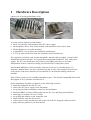
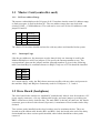
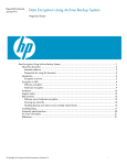
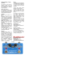
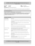
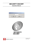
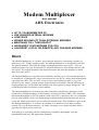
Modem Multiplexer
user manual
ADX Electronics
•
•
•
•
•
•
•
UP TO 128 MODEMS PER PC
USE CHEAPER INTRNAL MODEMS
LOW PRICE
HIGHER RELIABILITY THAN EXTERNAL MODEMS
MAINTAINS FULL THROUGHPUT
ORGANISES YOUR MODEMS FOR YOU
CAN RESET (LOCAL OR REMOTE) ANY CRASHED MODEMS
Blurb
The Modem Multiplexer is a fresher, more rational aproach to connecting a number of
modems to a PC. Unlike multiport cards, the Modem Multiplexer is designed specifically
for internal modems. The main advantage of internal modems is their price - even our
smallest systems can ‘pay for themselves’. Internal modems are also smaller and have far
less cables. The largest drawback with internal modems has been the inability to install
more than four in a PC.
The Modem Multiplexer overcomes this limitation. It allows up to 128 internal modems to
be installed in 16 standard PC cases, and connected to one PC in a daisy chain arrangement
via single bus cables. The use of PC cases to house the modems provides a very costeffective power supply, cooling system and protected environment. Plus the difficulty of
keeping plugboxes, serial cables and modems tidy and organised, simply disappears. The
result has generally been better system stability.
The Modem Multiplexer electronics provides extremely cost-effective multi-port serial
expansion by taking advantage of the modems’ on-board 16550A UARTs. This maintains
maximum throughput on all 128 modems (with a fast CPU), and allows the use of standard,
proven serial interface code. One disadvantage with internal modems has been the need to
power the whole system down if one suffers an internal crash. This limitation is gone with
the Modem Multiplexer, as it allows any modem to be hardware reset under software
control. This can be done remotely - an added advantage over external modems which
typically need their power removed.
It all adds up to a product with the combination of stability, throughput, cost and
dependability that your ISP application demands.
1
Hardware Description
(photos are of prototype hardware only)
backplane
controller
A system with 8 modems would include:
• Our 8 bit controller card installed in the PC (above right)
• Our backplane (above left) with a modem card installed in each of its 8 slots
• The backplane-to-case cable assembly
• A standard PC case to house the backplane and modems
• A 25 way cable which runs from the controller card to modem box
We supply the controller card, modem backplane, internal cable assembly, external cable,
manual and software patches. You supply the modems and standard PC case with power
supply. The PC case should have provision for two DB25 connectors to be fitted
independent of the 8 card slots (usually provided for RS232 and printer ports).
One Modem Multiplexer 8-bit controller card can service up to 4 modem boxes (32
modems). Modem boxes are daisy chained using the 25 way cable supplied. Four master
cards can be used in one machine for a maximum of 128 modems running off the one
machine.
Each of these cards uses its own IRQ and address space. The ISA bus bandwidth allows full
throughput of all 32 modems connected to it.
Quick Installation checklist (for details see the following sections)
• install the backplane into the PC case
• connect the PC power supply to the backplane
• set up jumpers and terminating resistors on the backplanes
• install the DB25 to header ribbon cable into the PC case and plug into backplane
• install up to 8 modems all set to COM4
• set up IRQ and address on the controller card
• intall controller card into the host PC
• connect power to the modem box and connect it to the PC using the cable provided
• apply software patches to you linux kernel
1.1 Master Card (controller card)
1.1.1 I/O Port Address Range
The master card multiplexes the I/O ports of all 32 modems into the same I/O address range,
so little port space is used in the host PC. The new address range does not clash with
existing COM1 -- COM4 addresses. The card can be set to one of four I/O addresses with
jumpers Jl and J2:
J1
Off
Off
On
On
J2
Off
On
Off
On
I/0(Hex)
100--l0F
110--11F
120--12F
130--13F
The chosen I/O locations should not interfere with any other card installed in the system.
1.1.2
Interrupt Usage
Like the port addresses, the interrupts are also shared. Only one interrupt is used by the
Modem Multiplexer card. Four jumpers J3-J6 specify the interrupt number to use. The
correspondence between the jumpers and the interrupt numbers is given in the following
table (note that IRQ9 is sometimes known as IRQ2). Only one of J3-J6 should be installed.
J3
J4
J5
J6
IRQ3
IRQ4
IRQ5
IRQ9
As is usual with PC cards, the IRQ chosen must not conflict with any other card present in
the machine. IRQ3 and IRQ4 are commonly used for COM ports 1, 2, 3 and 4.
1.2 Slave Board (backplane)
The slave board looks similar to a standard PC motherboard. It has 8 slots for modems, a PC
power supply connector, a 26 way ribbon cable header, and some jumpers. providing two
DB25 connectors to daisy chain the bus. The male DB25 is the bus-in connector, the female
connector goes to the next slave board (if present). A maximum of four boards can be daisy
chained.
Two resistor packs installed on the slave board are used to terminate the bus. These are
located near the ribbon cable header (RP1 and RP2). Only the board at the end of the daisy
chain should have these resistor packs installed, other boards should have these packs
removed.
1.2.1 Slave Board Jumpers
Two jumpers are present on the slave board to mark the board address 0-3. It is
recommended that the boards be addressed sequentially from the computer towards the end
of the bus. (Each address must be different, and the board connected to the computer must
be at address 0.)
1.2.2 Slave Board Installation
Install the slave board the same as you would install a PC motherboard. Ensure the PC
power supply leads are connected around the right way.
Remove the two resistor packs nearest the 26 way box header if this is not the last slave
board in the chain. Plug in the 26 way ribbon cable (it can only be installed one way round)
and install its male and female DB25 connectors into the PC case (using the printer port and
comm cutouts provided).
1.2.3 Modem Installation into Slave Board
The modems are installed physically as they would be in a PC, ensure the power is off first.
The modems should all be set to COM4 (IRQ3 and I/O base 02E8), according to the modem
manufacturers’ instructions.
There are no software restrictions on which slots the modems go in - the setup and
diagnostics procedure will automatically detect the presence of modems and indicate where
it thinks they are.
2 Software Drivers
Applying the patches
There are three linux kernel patches available which contain the source for the Modem
Multiplexer; one for kernel version 1.0.9, one for 1.2.13, and one for 2.0 kernels. There are
no patches available for the development kernels (1.1.x, 1.3.x, or 2.1.x), but all patches are
similar and may even apply cleanly to some of these kernels. The 2.0 patch will apply
cleanly to most 2.0.x versions (tested on 2.0 and 2.0.23).
All the patches do not add a new device to the kernel, but instead appear simply as new
serial ports (ttyS?? and cua??). As distributed, 16 modems are defined, on ttyS16 - ttyS31.
This can be easily extended by adding more entries into the serial table at the beginning of
serial.c. The I/O location is set to 0x100, and the interrupt number is 9. (this is the master
driver board's interrupt, not the actual modems' interrupts).
To apply any of the patches, use the standard invocation of patch, e.g:
cd /usr/src
patch -p0 <mdms-diff-2.0
then rebuild your kernel in the normal way.
The devices ttyS16-ttyS31 and cua16-cua23 probably do not already exist in the /dev
directory. These can easily be created with the script (this must of course be run as root):
#!/bin/sh
i=16
j=`expr 64 + $i`
while [ ! $i = 32 ] ; do
mknod -m 644 /dev/ttyS$i c 4 $j
mknod -m 660 /dev/cua$i c 5 $j
chown root.uucp /dev/cua$i
i=`expr $i + 1`
j=`expr $j + 1`
done
After creating these devices, and using the new kernel, you will be able to use the modems
as if they were standard internal serial ports. The kernel messages from the driver that
appear during booting should look like the following:
Oct 16 22:37:17 garden kernel: tty00 at 0x03f8 (irq = 4) is a
16550A
Oct 16 22:37:17 garden kernel: tty01 at 0x02f8 (irq = 3) is a
16550A
Oct 16 22:37:17 garden kernel: Resetting modems at port 100
... followed by a line for each modem which is detected by the driver.
Some modems (both internal and external) could hang under some circumstances. With
external modems, it was always possible to turn them off and on, but this is not possible
with internal modems. To help this situation with these sort of modems, the ability to
hardware reset modems individually was included. The standard "setserial" command can
be used to reset the modem by using the "autoconfig" option. e.g. to reset the modem at
ttyS16 the following command can be used:
setserial /dev/ttyS16 autoconfig
3 Technical Description
The information in this section is to help you debug those frustrating ocassions, when
something like an IRQ conflict stops everything working. If only the manufacturer had told
you more about the workings of the product...
If the solution still escapes you after reading this section, feel free to contact us for support:
[email protected]
[email protected]
fax +64 3 3518484
Internal hardware description
The controller card is basically an ISA bus extender, which does most address decoding and
wait state generation needed for the long data bus.
The bus carries bidirectionl 8 bit data, partially decoded addresses, IO control lines and
interrupt request signal(s). Both ends of the bus are terminated to prevent reflections
interfering with data transmission.
The backplanes contain the registers and control circuitry to select and reset individual
modems, and interrupt priority encoding and storage. Modem data signals are buffered
before they reach the external world (25 way cable).
Internal Software Description
Much of the serial.c is unaltered, as the modems emulate a standard serial port. The only
differences required are to handle the multiplexing of all the devices to one set of I/O
locations, and the multiplexing of all the modem interrupts to a single interrupt.
A further addition is the ability to perform a hardware reset on any modem card without
having to reboot the computer. This hardware reset is also performed on all modems during
kernel initialisation.
The 1.0.9 patches do not use the interrupt identification to determine which modem(s)
caused an interrupt. This is because the interrupt routine can be called at a time when no
modem is generating an interrupt, but a modem does need to be serviced. For this reason,
the 1.0.9 version is less efficient than the 1.2.13 and 2.0 patches, especially when handling a
large number of modems.
The "hub6" value in the serial device structure is used in a slightly different way than
before. In all original versions of the kernel, if this value was non-zero, the serial port was
assumed to be a hub6 card. After the patch, a flag was defined for this purpose, and another
flag for the Modem Multiplexer. The "hub6" value is used by the Modem Multiplexer ports
as the value which must be written to the modem select register. The changes to handle this
are in the serial_in and serial_out routines.
A minor speed improvement has been added when receiving characters from a serial device.
This applies to all serial ports, not just the Modem Multiplexer ports.
A separate interrupt routine is used for the Modem Multiplexer interrupts, even if there is
only one port active. In all kernel versions except 1.0.9, the interrupt identification is read to
determine which card needs to be serviced. This is always read twice, to make sure the
value was not changing while it was being read. After servicing one card, this register is
checked again to see if any other card is also generating an interrupt. A loop counter makes
sure the interrupt servicing does not continue forever.
4 Other stuff
• Copyright (C) ADX Electronics 1997 all rights reserved. The information relating to this
product including the manual, product design and three-dimensional copies thereof (ie
the physical product) is protected by copyright and must not be copied in any way unless
expressly permitted by ADX Electronics.
• Disclaimer: ADX Electronics will not be liable for anything whatsoever, as the product is
‘borrowing’ the brand name and business trading name of Antony Dean (a private
individual). The partnership of Antony Dean and Mark Tomlinson will make all
reasonable attempts to provide the product and service advertised, and uphold a fair
supplier-customer relationship, however we can not be held responsible for matters out
of our control, and will not be liable for anything bad that may happen to anyone through
use of our product.
• The modem multiplexer is warranted against defects in workmanship for a period of two
years from the date it is supplied (or shipped). The warranty will not be automatically
invalidated if the product is modified or if you attempt a repair, but naturally your
workmanship will not be covered! IF YOU BLOW IT UP please say - we are in the best
position to replace or repair, and will try to do this at minimum cost and inconvenience to
you. We are in the business of making a good product, not repairing a bad one.
• Electromagnetic Compatibility (EMC): The modem multiplexer is a component in a
computing system; it is the customer’s responsibility to ensure that the complete system
does not interfere with nearby radio and television reception, and must accept
responsibility for any mis-operation of the product caused by transmitters. For minimum
EMC problems, the hardware should be installed into proper PC cases and all ISA cards
screwed firmly into place. Ensure that you are using the original shielded 25-way daisychain cable. If all else (including re-orienting the receiving antenna...) fails, try clip on
ferrites (generally the longer they are and more they weigh the better) on all leads as
close to the boxes as possible. If high powered transmiters are to be used in the vicinity
of the system, it pays to check them out up close for confidence. Generally anything
inside a PC case has excellent RF immunity.
• Customer protection: You are our source of income, clearly. But that doesn’t stop some
companies putting “profit” in the bottom line of their mission statement. After all, if you
can get away with it and it makes more money then it must be good for the business...
We don’t work that way, we prefer to ‘tell it like it is’ - there’s no need to mislead when
you’re selling a product rather than an ‘inflation’. (spot the cliches) We prefer
arrangements where the customer gets what they pay for and vice versa, and this is what
we undertake to uphold.
• ADX Electronics works to the spirit of the ISO9001 quality system (not accredited
because of the overhead). PCBs are manufactured in accordance with IPC standards.
Manufacturing is carried out to an appropriate standard (ie static precautions are
observed, approved components are used, product is 100% tested), and is currently
carried out at the facilities of a medical equipment manufacturer.
• Beta-feedback button (click here). Even though the modem multiplexer has been stable
for more than a year, we want to encourage user feedback and suggestions. Think of it as
beta product that happens to be more stable than a lot of ‘final releases’ on the market.
Don’t hold back your suggestions - after all, no product is ever truly finished. (Even
though this change from the mmux’s previous 1995 revision was mainly for cosmetic
reasons only...)
(this page wasn’t intentionally left blank, the wordprocessor decided to put it in)