1
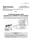
Ethernet Interface
Module
User's Manual
(Hardware)
QJ71E71-100
QJ71E71-B5
QJ71E71-B2
Thank you for purchasing the Mitsubishi programmable controller
MELSEC-Q Series.
Prior to use, please read both this and relevant manual thoroughly to
fully understand the product.
MODEL QJ71E71-U-HW-JE
MODEL
13JQ35
CODE
IB(NA)-0800009-I(1004)MEE
©1999 MITSUBISHI ELECTRIC CORPORATION
z SAFETY PRECAUTIONS z
(Read these precautions before using this product.)
Before using this product, please read this manual and the relevant manuals
carefully and pay full attention to safety to handle the product correctly.
Note that these precautions apply only to this product. For the safety instructions
of the programmable controller system, please read the user's manual of the
CPU module to use.
In this manual, the safety precautions are classified into two levels:
"
WARNING" and "
CAUTION".
Indicates that incorrect handling may cause hazardous
WARNING conditions, resulting in death or severe injury.
CAUTION
Indicates that incorrect handling may cause hazardous
conditions, resulting in minor or moderate injury or property
damage.
Under some circumstances, failure to observe the precautions given under
" CAUTION" may lead to serious consequences.
Make sure that the end users read this manual and then keep the manual in a
safe place for future reference.
[Design Precautions]
CAUTION
z Do not bunch the control wires or communication cables with the main circuit
or power wires, or install them close to each other.
They should be installed 100 mm (3.94 inch) or more from each other.
Not doing so could result in noise that would cause erroneous operation.
[Installation Precautions]
CAUTION
z Use the programmable controller in the operating environment that meets
the general specifications described in the user's manual of the CPU Module
to use.
Using this programmable controller in an environment outside the range of
the general specifications could result in electric shock, fire, erroneous
operation, and damage to or deterioration of the product.
A-1
[Installation Precautions]
CAUTION
z While pressing the installation lever located at the bottom of module, insert
the module fixing tab into the fixing hole in the base unit until it stops. Then,
securely mount the module with the fixing hole as a supporting point.
Incorrect loading of the module can cause a malfunction, failure or drop.
When using the programmable controller in the environment of much
vibration, tighten the module with a screw.
z Tighten the screw in the specified torque range.
Undertightening can cause a drop, short circuit or malfunction.
Overtightening can cause a drop, short circuit or malfunction due to damage
to the screw or module.
z Completely turn off the externally supplied power used in the system before
mounting or removing the module. Not doing so could result in damage to
the product.
z Do not directly touch the module's conductive parts or electronic
components.
Touching the conductive parts could cause an operation failure or give
damage to the module.
[Wiring Instructions]
CAUTION
z Use crimp-contact, pressure-displacement or soldering to wire the
connectors for external connections properly using the
manufacturer-specified tools.
Imperfect connections could result in short circuit, fires, or erroneous
operation.
z Shut off the external power supply for the system in all phases before
connecting the AUI cable.
z When connecting a cable with connector to the module, connect the
connector part to the module securely.
z Make sure to place the communication and power cables to be connected to
the module in a duct or fasten them using a clamp.
If the cables are not placed in a duct or fastened with a clamp, their positions
may be unstable or moved, and they may be pulled inadvertently. This may
damage the module and the cables or cause the module to malfunction
because of faulty cable connections.
z Tighten the terminal screws with the specified torque.
If the terminal screws are loose, it could result in short circuits, fire, or
erroneous operation.
Tightening the terminal screws too far may cause damages to the screws
and/or the module, resulting in fallout, short circuits, or malfunction.
A-2
[Wiring Instructions]
CAUTION
z When disconnecting the communication and power cables from the module,
do not pull the cables by hand. When disconnecting a cable with a
connector, hold the connector to the module by hand and pull it out to
remove the cable. When disconnecting a cable connected to a terminal
block, loosen the screws on the terminal block first before removing the
cable. If a cable is pulled while being connected to the module, it may cause
the module to malfunction or damage the module and the cable.
z Be sure there are no foreign substances such as sawdust or wiring debris
inside the module.
Such debris could cause fires, damage, or erroneous operation.
z The module has an ingress prevention label on its top to prevent foreign
matter, such as wire offcuts, from entering the module during wiring.
Do not peel this label during wiring.
Before starting system operation, be sure to peel this label because of heat
dissipation.
z Solder the coaxial cable connectors properly. Incomplete soldering may
result in malfunctions.
A-3
z CONDITIONS OF USE FOR THE PRODUCT z
(1) Mitsubishi programmable controller ("the PRODUCT") shall be used in
conditions;
i) where any problem, fault or failure occurring in the PRODUCT, if any, shall
not lead to any major or serious accident; and
ii) where the backup and fail-safe function are systematically or automatically
provided outside of the PRODUCT for the case of any problem, fault or failure
occurring in the PRODUCT.
(2) The PRODUCT has been designed and manufactured for the purpose of
being used in general industries.
MITSUBISHI SHALL HAVE NO RESPONSIBILITY OR LIABILITY
(INCLUDING, BUT NOT LIMITED TO ANY AND ALL RESPONSIBILITY OR
LIABILITY BASED ON CONTRACT, WARRANTY, TORT, PRODUCT
LIABILITY) FOR ANY INJURY OR DEATH TO PERSONS OR LOSS OR
DAMAGE TO PROPERTY CAUSED BY the PRODUCT THAT ARE
OPERATED OR USED IN APPLICATION NOT INTENDED OR EXCLUDED
BY INSTRUCTIONS, PRECAUTIONS, OR WARNING CONTAINED IN
MITSUBISHI'S USER, INSTRUCTION AND/OR SAFETY MANUALS,
TECHNICAL BULLETINS AND GUIDELINES FOR the PRODUCT.
("Prohibited Application")
Prohibited Applications include, but not limited to, the use of the PRODUCT
in;
y Nuclear Power Plants and any other power plants operated by Power
companies, and/or any other cases in which the public could be affected if
any problem or fault occurs in the PRODUCT.
y Railway companies or Public service purposes, and/or any other cases in
which establishment of a special quality assurance system is required by
the Purchaser or End User.
y Aircraft or Aerospace, Medical applications, Train equipment, transport
equipment such as Elevator and Escalator, Incineration and Fuel devices,
Vehicles, Manned transportation, Equipment for Recreation and
Amusement, and Safety devices, handling of Nuclear or Hazardous
Materials or Chemicals, Mining and Drilling, and/or other applications
where there is a significant risk of injury to the public or property.
Notwithstanding the above, restrictions Mitsubishi may in its sole discretion,
authorize use of the PRODUCT in one or more of the Prohibited Applications,
provided that the usage of the PRODUCT is limited only for the specific
applications agreed to by Mitsubishi and provided further that no special
quality assurance or fail-safe, redundant or other safety features which
exceed the general specifications of the PRODUCTs are required. For details,
please contact the Mitsubishi representative in your region.
A-4
Revisions
The manual number is given on the bottom right of the cover.
Print Date
Sep., 1999
Dec., 1999
May, 2001
Manual Number
Revision
IB(NA)-0800009-A First printing
IB(NA)-0800009-B
Addition
"Compliance with the EMC Directive and the Low Voltage
Directive"
Correction
Chapter 2, Section 5.2 POINT
IB(NA)-0800009-C Put Windows® base software products together from
Mitsubishi Programmable Logic Controller MELSEC
series to Mitsubishi integrated FA software MELSOFT
series.
Standardize the name from software package (GPP
function) to Product name (GX Developer.)
Correction
"SAFETY PRECAUTIONS", "Manuals", "Compliance with
the EMC Directive and the Low Voltage Directive",
Chapter 1, Chapter 2, Chapter 6, Chapter 7.
IB(NA)-0800009-D Additional model
QJ71E71-100
Sep., 2001
IB(NA)-0800009-E
Correction
Chapter 2, Chapter 3, Chapter 4,
Section 5.1 POINT, Section 5.2 POINT, Chapter 6
Apr., 2003
IB(NA)-0800009-F
Additional model
QJ71E71-B5
Deleted model
QJ71E71
Sep., 2000
Mar., 2006
IB(NA)-0800009-G
Sep., 2008
IB(NA)-0800009-H
Correction
"SAFETY PRECAUTIONS", "Compliance with the EMC
and Low Voltage Directives", Section 3.1, Chapter 7
Correction
"SAFETY PRECAUTIONS", "Compliance with the EMC
and Low Voltage Directives", Section 3.1, Chapter 4,
Section 5.2, Chapter 7
Apr., 2010
IB(NA)-0800009-I
Addition
"CONDITIONS OF USE FOR THE PRODUCT"
Correction
"SAFETY PRECAUTIONS", Chapter 4, Section 5.2,
Chapter 7
This manual confers no industrial property rights or any rights of any other kind, nor does
it confer any patent licenses. Mitsubishi Electric Corporation cannot be held responsible
for any problems involving industrial property rights which may occur as a result of using
the contents noted in this manual.
© 1999 MITSUBISHI ELECTRIC CORPORATION
A-5
CONTENTS
1. Overview ........................................................................................................1
2. Performance Specifications............................................................................1
3. Loading and Installation .................................................................................3
3.1 Handling Precautions...............................................................................3
3.2 Installation Environment...........................................................................3
4. Part Names ....................................................................................................3
5. Connecting to the Network .............................................................................4
5.1 Connecting to the 10BASE-T/100BASE-TX .............................................4
5.2 Connecting to the 10BASE5 ....................................................................6
5.3 Connecting to the 10BASE2 ....................................................................7
6. Setting from GX Developer.............................................................................8
7. External Dimensions ......................................................................................9
About Manuals
The following table lists manuals regarding this product.
Use this table to order necessary manuals respective to the functions used.
Related Manuals
Manual name
Q Corresponding Ethernet Interface Module User's Manual
(Basic)
Q Corresponding Ethernet Interface Module User's Manual
(Application)
Q Corresponding Ethernet Interface Module User's Manual
(Web function)
MELSEC-Q/L MELSEC Communication Protocol Reference
Manual
Manual No.
(Model code)
SH-080009
(13JL88)
SH-080010
(13JL89)
SH-080180
(13JR40)
SH-080008
(13JF89)
Please read the Q Corresponding Ethernet Interface Module User's Manual (Basic)
before using this module.
A-6
Compliance with the EMC and Low Voltage Directives
(1) For programmable controller system
To configure a system meeting the requirements of the EMC and Low
Voltage Directives when incorporating the Mitsubishi programmable
controller (EMC and Low Voltage Directives compliant) into other
machinery or equipment, refer to Chapter 9 "EMC AND LOW VOLTAGE
DIRECTIVES" of the QCPU User's Manual (Hardware Design,
Maintenance and Inspection).
The CE mark, indicating compliance with the EMC and Low Voltage
Directives, is printed on the rating plate of the programmable controller.
(2) For the product
For the compliance of this product with the EMC and Low Voltage
Directives, refer to Section 9.1.3 "Cables" in Chapter 9 "EMC AND LOW
VOLTAGE DIRECTIVES" of the QCPU User's Manual (Hardware Design,
Maintenance and Inspection).
A-7
1. Overview
This manual describes how to install the QJ71E71-100/QJ71E71-B5/QJ71E71B2 Ethernet interface modules (hereinafter referred to as Ethernet modules) and
how to wire them with external devices.
(Product Configuration)
Model
QJ71E71-100
QJ71E71-B5
QJ71E71-B2
Item name
QJ71E71-100 Ethernet interface module
QJ71E71-B5 Ethernet interface module
QJ71E71-B2 Ethernet interface module
Quantity
1
1
1
2. Performance Specifications
The following describes the performance specifications of the Ethernet module.
For the general specifications of the Ethernet module, refer to the user's manual
for the CPU module used.
Specification
QJ71E71-100
Item
Data transmission
speed
Transmission
method
Maximum
Transnode-to-node
mission
distance
specifiMaximum segment
cations
length
Maximum number of
nodes/connection
Interval between the
minimum nodes
Number of
simultaneously open
Transconnections allowed
mission
Fixed buffer
data
Random access
storage
buffer
memory
Attached file
E-mail
Main text
Number of I/O points occupied
5 V DC internal current
consumption
12 V DC external power supply
capacity (Transceiver)
External dimensions
Weight
100BASE-TX
100 Mbps
(Full-duplex/Half-duplex)
10BASE-T
10 Mbps (Half-duplex)
Base band
—
100 m (328.08 ft.) ( 1)
Cascade connection
Maximum 2 stages
Cascade connection
Maximum 4 stages
—
16 connections (Connections usable by the sequence program)
1 k words
16
6 k words
1
6 k words 1 ( 2)
960 words 1 ( 2)
32 points/1 slot (I/O assignments: intelligent)
0.50 A
—
98 (3.86 in.) (H)
1
27.4 (1.08 in.) (W) 90 (3.54 in.) (D) [mm]
0.11 kg (0.24 Ib.)
Specification
Item
Data transmission
speed
Transmission
method
Maximum
Transnode-to-node
mission
distance
specifiMaximum segment
cations
length
Maximum number of
nodes/connection
Interval between the
minimum nodes
Number of
simultaneously open
Transconnections allowed
mission
Fixed buffer
data
Random access
storage
buffer
memory
Attached file
E-mail
Main text
Number of I/O points occupied
5 V DC internal current
consumption
12 V DC external power supply
capacity (Transceiver)
External dimensions
Weight
QJ71E71-B5
10BASE5
QJ71E71-B2
10BASE2
10 Mbps (Half-duplex)
Base band
2500 m (8202.10 ft.)
925 m (3034.77 ft.)
500 m (1640.42 ft.)
185 m (606.96 ft.)
100 units/ segment
30 units/ segment
2.5 m (8.20 ft.)
0.5 m (1.64 ft.)
16 connections (Connections usable by the sequence program)
1 k words
16
6 k words
1
6 k words 1 ( 2)
960 words 1 ( 2)
32 points/1 slot (I/O assignments: intelligent)
0.50 A
0.60 A ( 4)
( 3)
—
98 (3.86 in.) (H) 27.4 (1.08 in.) (W) 90 (3.54 in.) (D) [mm]
0.12 kg (0.26 Ib.)
0.13 kg (0.29 Ib.) ( 4)
1: Length between the Hub and node.
2: Regarding the specifications of the e-mail transmission and reception
function, refer to the Ethernet module Users Manual (Basic) or the Users
Manual (Application).
3: It is necessary to apply a transceiver, or a device that meets AUI cable
specifications.
4: The product with first 5 digits of serial number "05049" or earlier is different
as follows:
• 5V DC internal current consumption: 0.70A
• Weight: 0.14kg (0.31lb.)
2
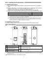
3. Loading and Installation
3.1 Handling Precautions
(1) Do not drop or apply severe shock to the module case since it is made of
resin.
(2) Always make sure to touch the grounded metal to discharge the electricity
charged in the body, etc., before touching the module.
Failure to do so may cause a failure or malfunctions of the module.
(3) Tighten the screws such as module fixing screws within the following range.
Screw location
External power supply terminal screw (M2.5 screw) ( 1)
Module fixing screw (usually not required) (M3 screw) ( 2)
Tightening torque range
0.40 N•m
0.36 to 0.48 N•m
1: This terminal is used as an external power input terminal for supplying power to the
transceiver when being connected to a 10BASE5.
2: The module can be easily fixed onto the base unit using the hook at the top of the
module. However, it is recommended to secure the module with the module fixing
screw if the module is subject to significant vibration.
3.2 Installation Environment
For further details, refer to the user's manual for the CPU module to use.
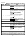
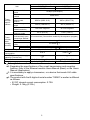
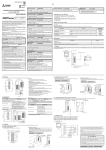
4. Part Names
1)
1)
1)
3)
4)
2)
5)
6)
Name
1) LED display (Refer to 1) )
10BASE-T/100BASE-TX
2)
connector (RJ45) ( 1)
3) 10BASE5 connector
4) 10BASE2 connector
6)
6)
Name
External power supply terminal
5) (Transceiver power supply)
(Input power supply reference value: 13.28 V to 15.75 V)
6) Serial number plate ( 2)
1: The orientation of the connector is different (rotated) depending on the serial No.
Although an LED may be built in the connector depending on the serial No. of the module,
it will not turn on.
2: Indicates the serial No. of the Ethernet module.
3
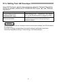
(1) LED display contents
LED display
QJ71E71-100
RUN
INIT.
OPEN
SD
ERR.
COM.ERR.
100M
RD
ERR.
COM.ERR.
RD
SD
ERR.
COM.ERR.
QJ71E71-B2
RUN
INIT.
OPEN
SD
INIT.
OPEN
QJ71E71-B5
RUN
INIT.
OPEN
SD
RUN
ERR.
COM.ERR.
100 M
RD
RD
Display contents: ( :Off : On)
: Normal operation
: Abnormal operation
: Initial processing normal completion
: Initial processing not performed
: Normally opened connection available ( 1)
: Normally opened connection not available
: Data being sent
: Data is not sent
: Setting abnormal display ( 2)
: Normal setting display
: Communication abnormal display
: Normal communication display
: 100 M bps
: 10 M bps/When not connected
: Data being received
: Data not received
1: The [OPEN] LED turns on/off depending on the open states of user connections 1 to
16.
2: The [ERR.] LED turns on in the following cases:
• When setting values in GX Developer (mode, station number, and/or network
number) are incorrect.
• When an error has occurred in the Ethernet module or programmable controller
CPU and the operation is disabled due to the error.
5. Connecting to the Network
The following describes how to connect the Ethernet module to the 100BASE-TX,
10BASE-T, 10BASE5 and 10BASE2.
POINT
Sufficient safety precautions are required when installing the 100BASE-TX,
10BASE-T, 10BASE5 and 10BASE2 networks. Consult a specialist when
connecting cable terminals or installing trunk line cables, etc.
5.1 Connecting to the 10BASE-T/100BASE-TX
<Connection procedure>
1) Connect the twisted pair cable to the
hub.
2) Connect the twisted pair cable to the
Ethernet module.
4
POINT
During the high-speed communication (100 M bps) via 100BASE-TX
connection, a communication error may occur due to the effect of high
frequency noise from devices other than programmable controller in a given
installation environment.
The following describes countermeasures on the QJ71E71-100 side to prevent
the effect of high frequency noise for construction of network system.
(1) Wiring connection
• Do not bundle the twisted pair cables with the main circuit and the power
wires, and do not install them close to each other.
• Make sure to place the twisted pair cables in a duct.
(2) Communication method
• Data communication with an external device is performed using TCP/IP
communication.
• Increase the number of communication retries as necessary.
(3) 10 M bps communication
• Communication is performed at a data transmission rate of 10 M bps by
changing the connection hub for the QJ71E71-100 to a hub capable of
handling 10 M bps.
5
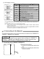
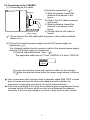
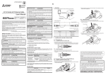
5.2 Connecting to the 10BASE5
(1) Connecting an AUI cable
<Connection procedure> ( 1)
Retainer
1) Slide the retainer toward the
A
direction B as shown in the
figure.
B
AUI cable
2) Push in the AUI cable connector
all the way.
3) Slide the retainer toward the
direction A as shown in the
figure.
4) Confirm that the AUI cable is
Transceiver DC
power supply
locked.
1: Do not connect the AUI cable while the power to the module installed
station is on.
(2) Wiring to the external power supply terminal (DC power supply for
transceiver ( 1))
The following explains how to connect a cable to the external power supply
terminal (DC power supply for transceiver).
1) Strip the cable jacket back 13mm. ( 2)
The applicable cable size is 0.13mm2 (AWG26) to 2.5mm2 (AWG14).
13mm
(0.51 in.)
2) Loosen the terminal screw and insert the cable into the terminal.
3) Tighten the terminal screw within the torque range shown in Section
3.1.
1:Use a transceiver with a function that is generally called SQE TEST or heart
beat (a transceiver function that emits signals to notify whether the
transceiver is operating normally at the end of communication).
2:If the wire strip length is too long, the conductive part is exposed and it may
increase the risk of electric shock or short circuit between the adjacent
terminals. If the wire strip length is too short, it may result in poor contact.
6
POINT
(1) The following can be used as a countermeasure for errors due to high
frequency noise according to the installation environment.
Mount a ferrite core using the method shown in (2) below.
Increase the retry number when communicating by TCP/IP.
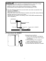
(2) Use the following method to mount a ferrite core when connected to the
network by 10BASE5.
(Mounting the ferrite core)
Mount the ferrite core to the Ethernet module side and the external device
side/the transceiver side for AUI cable.
(The ferrite core used for our testing: ZCAT 2032-0930 manufactured by
TDK Corporation)
QJ71E71-B5
AUI cable
Transceiver
Ferrite core
Coaxial cable for 10BASE5
5.3 Connecting to the 10BASE2
<Connection procedure>
1) Push in the connector by aligning
the groove [1] and tab [2] as shown
in the figure.
2) While pushing in the connector,
rotate it clockwise by a 1/4 turn.
3) Turn until the connector locks.
4) Check that the connector is locked.
[2]
[1]
7
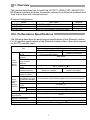
6. Setting from GX Developer
Using GX Developer, please make parameter setting for "Network Parameters
Setting the number of Ethernet/CC IE/MELSECNET cards" ( 1) and "Ethernet
Operations".
Item
Network parameters setting the
number of Ethernet/CC
IE/MELSECNET cards
Ethernet operations
Contents
Sets "Staring I/O No.", "Network No." and "Station
No." to use Ethernet module as Network module.
Sets "Communication data code", "IP address" and
"Initial timing" to perform initial processing of
Ethernet module.
Remarks
It is not necessary to set the "Intelligent function module switch settings" with GX Developer’s
I/O assignment.
Each type of setting corresponding to the switch settings is performed in the above
mentioned "Operational settings," "Initial settings," and "Open settings."
8
7. External Dimensions
(1) QJ71E71-100
(Units : mm (in.))
1: When connecting the twisted pair cable, set the bending radius near the connector
(reference value: R1) as four times the cable's outside diameter or larger.
2: The orientation of the connector is different (rotated) depending on the serial No.
(2) QJ71E71-B5
(Units : mm (in.))
1: When connecting the AUI cable, set the bending radius near the connector
(reference value: R2) as four times the cable's outside diameter or larger.
9
(3) QJ71E71-B2
4(0.16)
98 (3.86)
29.2 (1.15)
23.65
(0.93)
90 (3.54)
11.5
(0.45)
23
(0.91)
27.4(1.08)
(Units : mm (in.))
Ethernet is a trademark of Xerox Corporation.
All other company names and product names used in this manual are trademarks or
registered trademarks of their respective companies.
10
MEMO
11
Warranty
Mitsubishi will not be held liable for damage caused by factors found not to be the cause of
Mitsubishi; machine damage or lost profits caused by faults in the Mitsubishi products;
damage, secondary damage, accident compensation caused by special factors unpredictable
by Mitsubishi; damages to products other than Mitsubishi products; and to other duties.