1
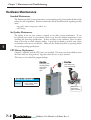
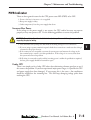
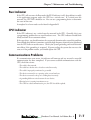
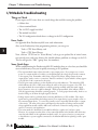
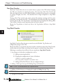
Maintenance and
Troubleshooting
Chapter
7
In This Chapter...
Hardware Maintenance.............................................................................................. 7–2
Diagnostics .............................................................................................................. 7–3
CPU Indicators............................................................................................................ 7–4
PWR Indicator ............................................................................................................ 7–5
RUN Indicator ............................................................................................................ 7–7
CPU Indicator ............................................................................................................. 7–7
Communications Problems........................................................................................ 7–7
I/O Module Troubleshooting..................................................................................... 7–8
Noise Troubleshooting............................................................................................. 7–10
Run Time vs. Stop Mode Transfer Instruction......................................................... 7–11
Forcing I/O Points.................................................................................................... 7–14
Chapter 7: Maintenance and Troubleshooting
1
2
3
4
5
6
7
8
9
10
11
12
13
14
A
B
C
D
Hardware Maintenance
Standard Maintenance
The Productivity2000 is a low maintenance system requiring only a few periodic checks to help
reduce the risks of problems. Routine maintenance checks should be made regarding two key
items.
• Air quality (cabinet temperature, airflow, etc.)
• CPU battery
Air Quality Maintenance
The quality of the air your system is exposed to can affect system performance. If you
have placed your system in an enclosure, check to see that the ambient temperature is not
exceeding the operating specifications. If there are filters in the enclosure, clean or replace
them as necessary to ensure adequate airflow. A good rule of thumb is to check your system
environment every one to two months. Make sure the Productivity2000 is operating within
the system operating specifications.
CPU Battery Replacement
A battery is included with the CPU, but is not installed. The battery can be installed to retain
the Time and Date along with any Tagname values that are set up as retentive.
The battery is not needed for program backup.
Step One:
Press spring lock
and swing battery
compartment
away from
CPU.
-
+ Step Two:
Insert battery and
close compartment.
Battery (Optional)
D2-BAT-1
7–2
Coin type, 3.0V Lithium
battery, 560mA, battery
number CR2354
2000
Hardware User Manual, 1st Edition, Rev. A
Take care to
insert battery
behind metal tab.
Chapter 7: Maintenance and Troubleshooting
Diagnostics
Diagnostics
Your Productivity2000 system performs many pre-defined diagnostic routines with every CPU scan.
The diagnostics have been designed to detect various types of failures for the CPU and I/O modules.
There are two primary error classes, critical and non-critical.
Critical Errors
Critical errors are errors the CPU has detected that offer a risk of the system not functioning safely or
properly. If the CPU is in Run Mode when the critical error occurs, the CPU will switch to Stop Mode
(Remember, in Stop Mode all outputs are turned off). If the critical error is detected while the CPU
is in Stop Mode, the CPU will not enter Run Mode until the error has been corrected. Here are some
examples of critical errors:
• Base power supply failure
• Parity error or CPU malfunction
• I/O configuration errors
• Certain programming errors.
Non-Critical Errors
Non-critical errors are flagged by the CPU as requiring attention. They can neither cause the CPU
to change from Run Mode to Stop Mode, nor do they prevent the CPU from entering Run Mode.
There are system tags the application program can use to detect if a non-critical error has occurred.
The application program can be used to take the system to an orderly shutdown or to switch the
CPU to Stop Mode if necessary.
Some examples of non-fatal errors are:
• Backup battery voltage low
• All I/O module errors
• Certain programming errors.
Finding Diagnostic Information
The CPU automatically logs critical and non-critical error codes. Logged errors can be found
in the following places marked with a time and date stamp:
• Displayed on OLED of the CPU module by scrolling through the menu.
• Under the Monitor Debug tool of ProductivitySuite, in the CPU Error History window, the 20
most recent critical and non-critical errors are listed.
Error Codes
See Appendix B “Productivity2000 Error Codes” for a complete list of error messages sorted
by error types.
2000
Hardware User Manual, 1st Edition, Rev. A
7–3
1
2
3
4
5
6
7
8
9
10
11
12
13
14
A
B
C
D
Chapter 7: Maintenance and Troubleshooting
1
2
3
4
5
6
7
8
9
10
11
12
13
14
A
B
C
D
CPU Indicators
The Productivity2000 CPU has indicators on the faceplate to help diagnose problems with
the system. The table below gives a quick reference of potential problems associated with each
status indicator. The pages following the table contain a detailed analysis of each of these
indicator problems.
Indicator Status
PWR (off)
RUN (will not come on)
CPU (blink)
Potential Problems
1. System voltage is incorrect.
2. Power supply/CPU is faulty.
3. Other components such as an I/O module has power supply
shorted.
1. CPU programming error
2. Switch in STOP position
CPU internal error
CPU Status Indicators
PWR
RUN
CPU
7–4
2000
Green LED is illuminated when power
is on
Green LED is illuminated when CPU is in
RUN mode
Red LED is illuminated during power on
reset, power down, or watch-dog time-out.
Hardware User Manual, 1st Edition, Rev. A
Chapter 7: Maintenance and Troubleshooting
PWR Indicator
There are three general reasons for the CPU power status LED (PWR) to be OFF:
1. Power to the base is incorrect or is not applied.
2. Base power supply is faulty.
3. Other component(s) have the power supply shut down.
Incorrect Base Power
If the voltage to the power supply is not correct, the CPU and/or base may not operate
properly or may not operate at all. Use the following guidelines to correct the problem.
WARNING: To minimize the risk of electrical shock, always disconnect the system power before
inspecting the physical wiring.
1. First, disconnect the system power and check all incoming wiring for loose connections.
2. If you are using a separate termination panel, check those connections to make sure the wiring is
connected to the proper location.
3. If the connections are acceptable, reconnect the system power and measure the voltage at the
base terminal strip to ensure it is within specification. If the voltage is not correct, shut down
the system and correct the problem.
4. If all wiring is connected correctly and the incoming power is within the specifications required,
the base power supply should be returned for repair.
Faulty CPU
There is no simple test for a faulty CPU other than substituting a known good one to see if
this corrects the problem. If you have experienced major power surges, it is possible the CPU
and power supply have been damaged. If you suspect this is the cause, a line conditioner
should be installed on the incoming line. This will keep damaging voltage spikes from
reaching the CPU.
2000
Hardware User Manual, 1st Edition, Rev. A
7–5
1
2
3
4
5
6
7
8
9
10
11
12
13
14
A
B
C
D
Chapter 7: Maintenance and Troubleshooting
1
2
3
4
5
6
7
8
9
10
11
12
13
14
A
B
C
D
PWR Indicator, cont’d
Device or Module Causes the Power Supply to Shutdown
Module:
If the PWR LED is operating normally but the power supply shuts down, check each module
for a possible bent pin on the base connector as follows:
1. Turn off power to the base.
2. Remove a module from the base.
3. Reapply power to the base.
4. Check for power supply normal operation.
5. Repeat procedure until defective module is found and replaced.
Device:
A 5V charge may be originating from the base or CPU communications port.
Test as follows:
1. Turn off power to the CPU.
2. Disconnect all external devices (i.e., communication cables) from the CPU.
3. Reapply power.
4. If power supply operates normally then check for a shorted device or shorted cable.
7–6
2000
Hardware User Manual, 1st Edition, Rev. A
Chapter 7: Maintenance and Troubleshooting
Run Indicator
If the CPU will not enter the Run mode (the RUN indicator is off), the problem is usually
in the application program, unless the CPU has a critical error. If a critical error has
occurred, the CPU LED should be on. You can use a programming device to determine
the cause of the error.
A complete list of error codes can be found in Appendix B.
CPU Indicator
If the CPU indicator is on, a critical error has occurred in the CPU. Generally, this is not
a programming problem but an actual hardware error. The CPU indicator should blink
briefly and then do an automatic reboot.
If the error clears, you should monitor the system and determine what caused the problem.
You will find this problem is sometimes caused by high frequency electrical noise introduced
into the CPU from an outside source. Check your system grounding and install electrical
noise filters if the grounding is suspected. If power cycling the system does not reset the
error, or if the problem returns, you should replace the CPU.
Communications Problems
If a communication error occurs, the indicator will come on and stay on until a successful
communication has been completed. If you cannot establish communications with the
CPU, check these items:
• The cable is disconnected.
• The cable has a broken wire or has been wired incorrectly.
• The cable is improperly terminated or grounded.
• The device connected is not operating at the correct baud rate.
• The device connected to the port is sending data incorrectly.
• A grounding difference exists between the two devices.
• Electrical noise is causing intermittent errors.
• The CPU has a bad communication port; the CPU should be replaced.
2000
Hardware User Manual, 1st Edition, Rev. A
7–7
1
2
3
4
5
6
7
8
9
10
11
12
13
14
A
B
C
D
Chapter 7: Maintenance and Troubleshooting
1
2
3
4
5
6
7
8
9
10
11
12
13
14
A
B
C
D
I/O Module Troubleshooting
Things to Check
If you suspect an I/O error, there are several things that could be causing the problem.
• A blown fuse
• A loose terminal block
• The 24 VDC supply has failed
• The module has failed
• The I/O configuration check detects a change in the I/O configuration
Error Codes
See Appendix B for Productivity2000 error code information.
Also, in the Productivity Suite programming software, you can go to:
Tools > CPU Error History, and
Tools > CPU Event History
Next, click on “CPU Error”or “Event History” tab to get an updated list of critical errors,
non-critical errors and event history that should indicate problems or changes to the I/O.
This list will give the “GBS” (group, base, slot numbers).
Some Quick Steps
When troubleshooting the Productivity2000 I/O modules there are a few facts you should be
aware of which may assist you in quickly correcting an I/O problem:
• The output modules cannot detect shorted or open output points. If you suspect one or more
points on a output module to be faulty, you should measure the voltage drop from the common
to the suspect point. Remember, when using a Digital Volt Meter, leakage current from an
output device, such as a triac or a transistor, must be considered. A point which is off may appear
to be ON if no load is connected to the point.
• The I/O point status indicators on the modules are logic side indicators. This means the LED
which indicates the ON or OFF status reflects the status of the point in respect to the CPU. For
an output module, the status indicators could be operating normally, while the actual output
device (transistor, triac etc.) could be damaged. With an input module, if the indicator LED is
ON, the input circuitry should be operating properly. To verify proper functionality, check to see
that the LED goes off when the input signal is removed.
• Leakage current can be a problem when connecting field devices to I/O modules. False input
signals can be generated when the leakage current of an output device is great enough to turn on
the connected input device. To correct this, install a resistor in parallel with the input or output
of the circuit. The value of this resistor will depend on the amount of leakage current and the
voltage applied but usually a 10K to 20K resistor will work. Ensure the wattage rating of the
resistor is correct for your application.
• The easiest method to determine if a module has failed is to replace it if you have a spare.
However, if you suspect another device to have caused the failure in the module, that device may
cause the same failure in the replacement module as well. As a point of caution, you may want
to check devices or power supplies connected to the failed module before replacing it with a spare
module.
7–8
2000
Hardware User Manual, 1st Edition, Rev. A
Chapter 7: Maintenance and Troubleshooting
Testing Output Points
Output points can be set ON or OFF using the force function to override a point even while
the program is running. However, this is not a recommended method to test the output
points. If you want to do an I/O check independent of the application program, follow the
procedure in the table below:
Step
Action
1.
2.
3.
Use Productivity Suite programming software to communicate online to the CPU.
Change to Program Mode.
Go to the first rung of the ladder.
Insert a rung with an “END” statement. (This will cause program execution to occur only at address
0 and prevent the application program from turning the I/O points on or off).
Change to Run Mode.
Use the programming device to set (turn) on or off the points you wish to test.
When you finish testing I/O points delete the “END” statement at the first rung.
4.
5.
6.
7.
WARNING: Depending on your application, forcing I/O points may cause unpredictable machine
operation that can result in a risk of personal injury or equipment damage. Make sure you have taken
all appropriate safety precautions prior to testing any I/O points.
NOTE: The LED on Analog I/O modules displays actual voltage, current, and digital values without
connecting a meter.
2000
Hardware User Manual, 1st Edition, Rev. A
7–9
1
2
3
4
5
6
7
8
9
10
11
12
13
14
A
B
C
D
Chapter 7: Maintenance and Troubleshooting
Noise Troubleshooting
1
2
3
4
5
6
7
8
9
10
11
12
13
14
A
B
C
D
Electrical Noise Problems
Noise is one of the most difficult problems to diagnose. Electrical noise, whether conducted
or radiated, can enter a system in many different ways. It may be difficult to determine how
the noise is entering the system but the corrective actions for either type of noise problem are
similar.
• Conducted noise is when the electrical interference is introduced into the system by way of an
attached wire, panel connection, etc. It may enter through an I/O module, a power supply
connection, the communication ground connection, or the chassis ground connection.
• Radiated noise is when the electrical interference is introduced into the system without a direct
electrical connection, much in the same manner as radio waves.
Reducing Electrical Noise
While electrical noise cannot be eliminated completely, it can be reduced to a level that will not
affect system function. Proper grounding of components and signal wiring along with proper
isolation of voltages can minimize noise in the system.
1. Grounding:
• Most noise problems result from improper grounding of the system. A good earth ground can
be the single most effective way to correct noise problems. If a ground is not available, install a
ground rod as close to the system as possible.
• Ensure all ground wires are single point grounds and are not daisy chained from one device to
another. Ground metal enclosures around the system. A loose wire is no more than a large
antenna waiting to introduce noise into the system; therefore, you should tighten all connections in
your system. Loose ground wires are more susceptible to noise than the other wires in your system.
Review Chapter 5, “Installation and Wiring”, if you have questions regarding how to ground your
system.
2. Isolation:
• Electrical noise can enter the system through the power source for the CPU and I/O. Installing an
isolation transformer for all AC sources can correct this problem.
• DC power sources should be well grounded, good quality power supplies. Switching DC power
supplies commonly generate more noise than linear supplies.
• Separate input wiring from output wiring. Never run I/O wiring close to high voltage wiring.
7–10
2000
Hardware User Manual, 1st Edition, Rev. A
Chapter 7: Maintenance and Troubleshooting
Run Time vs. Stop Mode Transfer Instruction
Here we describe the actions and differences between Run Time & Stop Mode transfers as
shown in this dialog box.
The above dialog is accessed two ways: (only when CPU is online AND in run mode)
Perform either of the following to transfer project to the CPU:
1. Click on the “To CPU” icon on the Tool Bar, or
2. Click through from the File menu > Transfer Project > To CPU.
2000
Hardware User Manual, 1st Edition, Rev. A
1
2
3
4
5
6
7
8
9
10
11
12
13
14
A
B
C
D
7–11
Chapter 7: Maintenance and Troubleshooting
1
2
3
4
5
6
7
8
9
10
11
12
13
14
A
B
C
D
Run Time Transfers
Run Time Transfer allows the user to transfer edits to a project in the CPU without stopping
the CPU scan, therefore not stopping the process. Be aware that a Run Time Transfer will
affect the length of your scan time, which should be considered if your process is susceptible
to varying or lengthy scan times. The download time is longer compared to a Stop Mode
transfer.
During a Run Time transfer, the current project file continues running until the entire
project file is transferred to the CPU. Once downloaded, the ladder logic files swap and begin
executing the new file. The Tag Database is shared between the two project files during a Run
Time transfer, therefore current operating values will not be effected.
Because the Tag database is shared, any edits to the Tag database will force a Stop Mode
transfer.
Stop Mode Transfers
Stop Mode Transfers allows the user to transfer any and all ladder, Tag Database and
configuration changes to the CPU.
Because the CPU is in stop mode, the project transfer is much faster than a Run Time Transfer
and also loads all initial values to the tags once the project is switched from Stop to Run.
Following are conditions that will force the user to perform a Stop Mode Transfer:
1. Any changes to the hardware configuration, such as:
A. Adding or removing hardware.
B. Changing the configuration of a piece of hardware.
• Ethernet or serial port configuration.
• Hot swap enable or disable on any module or base.
C. Adding an EhterNet/IP device and any configured changes
2. Adding > 5000 tags of any type (Excluding Strings and Structures).
NOTE: This limit is accumulated between each stop mode transfer.
3. Adding >50,000 characters or changing the length of a String data type Tag.
NOTE: This limit is accumulated between each stop mode transfer.
4. Changes to Data Logger.
7–12
2000
Hardware User Manual, 1st Edition, Rev. A
Chapter 7: Maintenance and Troubleshooting
5. Changes to Modbus Server settings under Project Properties.
6. Changes to the buffer size for a FILI instruction.
7. Adding >5,000 elements of a Structures data type to Tag Database.
NOTE: This limit is accumulated between each stop mode transfer.
8. Enabling Bit of Word under Project Properties.
9. Enabling Structures in Project Properties.
10. Enable and Disable of EhterNet/IP Adapter.
As the CPU goes from Stop to Run after a Stop Mode Transfer, tags are initialized as if the
project is being executed for the first time. This includes Retentive Tags. If it’s desirable
that the values of Retentive Tags be retained through a Stop Mode Transfer, there are two
methods available. Both options may be enabled and they can be found under Tools >
Options > Project Transfer
1. Upload current retentive values and copy to initial values. This option works during
program upload. When selected, place the CPU in Stop Mode so Retentive Tag values
are stable, then upload the project. Productivity Suite will copy the current value of
all Retentive Tags to their Initial Values in the Tag Database of the project. Perform
your edits and transfer the project back to the CPU. When the CPU goes back to run,
your Retentive Tags will be initialized with their old values. This is a simple process
and is convenient for quick edits to the program, but the CPU must remain in Stop
Mode while the project is edited to ensure that no retentive values have changed during
editing.
2. Copy current retentive tag values to initial values. This option works during program
download. This process is more involved, but the CPU will use the values from the
project currently running as the initial values of the project being transferred. For more
information refer to the Options topic in the help file.
2000
Hardware User Manual, 1st Edition, Rev. A
1
2
3
4
5
6
7
8
9
10
11
12
13
14
A
B
C
D
7–13
Chapter 7: Maintenance and Troubleshooting
1
2
3
4
5
6
7
8
9
10
11
12
13
14
A
B
C
D
Forcing I/O Points
Following is a description of the actions, expectations and indications of forcing a value in the
Productivity2000 controller.
Advantages of Forces
Almost all tags can be written to in the software without Forcing. However, if the ladder
logic or an external device (operator interface panel, Modbus device, etc.) is connected to your
controller and writing to those tags, the values you write from a Data View will be over-written.
Conversely, if you write a Forced value, this will not be overwritten or reset until you manually
remove the force or reset by means of a Stop to Run mode transition, a Stop Mode Transfer,
or a controller power cycle.
Enabling Forces
The Productivity2000 CPU is a Tag based controller where forcing a tag begins by identifying
any tag you wish to be “Forceable” within the Tag database.
7–14
2000
Hardware User Manual, 1st Edition, Rev. A
Chapter 7: Maintenance and Troubleshooting
There are three columns within the Tag database that affect the forcing of all tags.
1. “Forceable” - Checking the box in this column identifies the corresponding tag as being able
to be forced within the system.
2. “Init Forced” - Checking the box in this column identifies that corresponding tag as being
forced as soon as the project is loaded and the processor is switched to Run mode.
3. “Init Force Value” - The state of the box in this column identifies the initial forced state of
the Boolean tag:
• A check mark in a box equates to a logical “1” or “ON”, and
• An unchecked box equates to a logical ”0” or “OFF”. The value placed in this field for Integer
or Floating point tags will be written into the tag.
Forcing Tags in Your System
All forcing of tags can be accomplished through the Data View window or directly in the
program interface while in “Monitor” mode, as long as the “Forceable” box has been
checked in Tag Database. I/O may also be directly forced in I/O View by clicking on
individual I/O points.
2000
Hardware User Manual, 1st Edition, Rev. A
1
2
3
4
5
6
7
8
9
10
11
12
13
14
A
B
C
D
7–15
Chapter 7: Maintenance and Troubleshooting
From the DataView Window, enter the tags you wish to force, or you can view all forceable
tags from the “Forceable Tags” tab automatically created for you when you enable tags as
forceable in the tag database.
1
2
3
4
5
6
7
8
9
10
11
12
13
14
A
B
C
D
From either of these windows you have the option to select the check box in the Force column.
When this box is checked and the row is selected (selected rows show high-lighted blue) and
you select the Send Edit(s) button, the current row(s) will be forced.
NOTE: You can select multiple rows by clicking and holding down the left mouse button and dragging up or
down. This selects consecutive rows. If you wish to select various rows, simple hold the “Ctrl” control key
on your keyboard while left mouse clicking the rows.
7–16
2000
Hardware User Manual, 1st Edition, Rev. A
Chapter 7: Maintenance and Troubleshooting
Identifying Forced Values
There are two indications that forces are active on your controller.
1. All active forces will be shown in the Forceable tab of the Data View window as shown in the
previous view.
2.You will also see “CPU Data Forced” in Red in the lower right of the Status bar of your
software interface.
NOTE: Only Forced tags with an initial force value specified in the Tag database will be retained after
a Stop to Run transition, Stop Mode transfer, or a power cycle. All forced values are retained during a
Run Time transfer.
2000
Hardware User Manual, 1st Edition, Rev. A
1
2
3
4
5
6
7
8
9
10
11
12
13
14
A
B
C
D
7–17
Chapter 7: Maintenance and Troubleshooting
Force Value Timing Chart
The chart below shows how the states of a Digital Output are varied when forces and edits are
applied. The ladder rung at the top of the chart (a) shows the logical arrangement of Logical
Contact1 and Digital Output DO-0.1.3.1.
Under normal operation, Logical Contact1 (b) is driven by a clock pulse. This clock pulse
is then fed to the Digital Output DO-0.1.3.1 (c). Edits written to the contact or the coil
from the Data View window within the software will be written one time and will not be
forced. With the clock pulse driving the contact, any software edits made to this contact will
be allowed but will be overwritten by the logic on the very next scan. Any software edits made
to the output will not be allowed and will not register. Edits can only change the state of the
output if there are no other logistic or outside factors influencing the output.
In order to change the state of Logical Contact1 or Digital Output DO-0.1.3.1 while the
clock pulse is driving it, a force must be introduced. The DO-0.1.3.1 Output Edit line (d)
represents edits sent to the digital output from the Data View window. The DO-0.1.3.1
Output Force Enabled line (e) shows the point at which the software forces the output edit
to take effect. The dotted lines represent the force being enabled and then disabled by the
user. When the force is enabled, any edits made will register at the output regardless of Logical
Contact1’s state. When the force is disabled, all output edits will be ignored.
1
2
3
4
5
6
7
8
9
10
11
12
13
14
A
B
C
D
7–18
2000
Hardware User Manual, 1st Edition, Rev. A