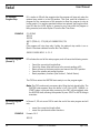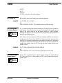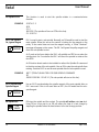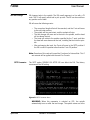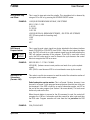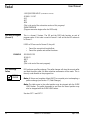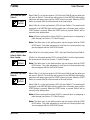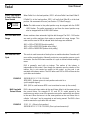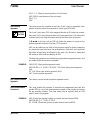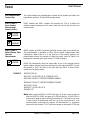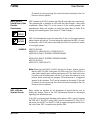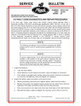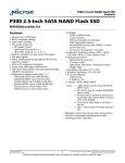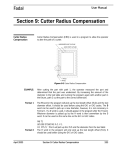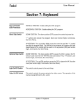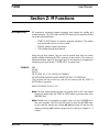
1
Fadal User Manual Section 2: M Functions M0 Program Stop M0 temporarily suspends program execution and cancels the spindle and coolant functions. The CNC enters the WAITING state until the operator pushes one of the following buttons: • • • START or AUTO button (to continue program execution). The coolant and spindle will not turn on unless coded. MANUAL (aborts program execution). JOG (initiates the jog away feature). Using the jog away feature, any axis can be moved away from its current position without disturbing the CNC’s memory of that position. This allows an optional automatic return of the jogged axes to that position to complete the machining cycle (see Section 7, SLIDE HOLD, Jog away from). EXAMPLE: G80 M5 M9 G53 Z0 M6 T3 (TOOL #3, .5 2FL HSS EM .01 C'RADIUS M0 (OPERATOR CHANGE CLAMPS FROM POSITION 1 TO POSITION 2 (The program will stop at this line, and will not continue until the START or AUTO button is pressed). G90 G0 S7500 M3 E1 X1.43 Y-2.7 Note: The look ahead processing does not continue past an M0. Look ahead processing begins after the START or AUTO button is pressed while in the WAITING state. Note: Another way to accomplish a program stop is to use G4 P66000 on a line in the program. This will cause the control to enter the WAITING state. In this case the spindle and coolant will not be turned off and the look ahead processing will continue beyond the G4 code (see Chapter 3, G Codes). April 2003 Section 2: M Functions 21 Fadal User Manual M1 Optional Program Stop EXAMPLE: M1 is similar to M0 with the exception that the program will stop only when the optional stop switch is in the ON position. This code could be included in a program for the convenience of the operator to allow the program to stop at certain points. For machine pendants without an optional stop toggle switch, type MU after the AUTO button is pressed or any time while the program is being executed, and select Option 2 from the Run Time Menu. Z.1 G0 G40 M5 M9 G53 Z0 M6 T5 (TOOL #5, .375 (3/8) 4FL CARBIDE EM, TIN M1 (The program will stop here only if either the optional stop switch is on or Option 2 has been selected from the Run Time Menu). G90 G0 S10000 M3 E1 X-.3 Y-.2 M2 End of Program (Format 1) M2 indicates the end of the main program, and will cause the following events: • • • • • Cancel the current tool length offset. Cancel the fixture offset and move to the current position at E0. Return all axes to the home position and move to the SETH position. Cancel the spindle and coolant function. Reset preparatory functions (See Section 1, Default Status). The CNC then enters the WAITING state ready to run the program again. Note: The CNC continuously processes data, filling the look ahead buffer. The WAITING state appears when the buffer is full. If the AUTO, MANUAL, or START button is pressed while processing, the CNC will immediately enter the WAITING state, allowing the operator to press START or AUTO to begin execution. M2 End of Program (Format 2) EXAMPLE: In Format 2, M2 acts as an M30 to mark the end of the main program and will only: • cancel the current tool length offset. • cancel the spindle and coolant functions. Formats 1 & 2 M5 M9 22 Section 2: M Functions April 2003 Fadal User Manual G53 Z0 M6 T1 E0 X0 Y0 M2 (This is the end of the main program). M3 Spindle CW EXAMPLE: M3.1 Sub-Spindle On, Ignore Magnet 9 SPECIAL FEATURE M3 is used to start spindle rotation in a clockwise direction. M6 T7 (TOOL #7, #1 C’DRILL M1 G90 G0 S300 M3 E1 X0 Y0 (The spindle will turn on CW at this line). M3.1 is used to start a sub-spindle. Normally an M3 would be used to start the main spindle. When this occurs, the control is looking for the magnet on the pulley. If the control does not see the magnet turning, a “Motor Overload” message will appear on the screen. The M3.1 will ignore the pulley magnet and direct the sub-spindle to start. An S word on the line or before the M3.1 will establish an RPM to use when the spindle starts. An S word after the M3.1 will direct the spindle to rotate at the new RPM. An M function board needs to be installed to redirect the Spindle-On command to the drive system of the sub-spindle. Use an M5 to stop the subspindle from rotating. See also M3.2 to use the main spindle after the subspindle is used. EXAMPLE: M3.2 Acknowledge Spindle Magnet 9 SPECIAL FEATURE April 2003 M6 T7 (TOOL#7,BLANK TOOL FOR SUB-SPINDLE M1 G90 G0 S300 M3.1 E1 X0 Y0 (The sub-spindle will start at this line). Use an M3.2 to acknowledge the spindle magnet of the main spindle after an M3.1 was used. If this is not used after an M3.1, the M3 would start the subspindle again. Section 2: M Functions 23 Fadal User Manual M4 Spindle CCW EXAMPLE: M4.1 Sub-Spindle On, Ignore Magnet 9 SPECIAL FEATURE This function is used to start the spindle rotation in a counterclockwise direction. X3.674 Y1.5 M19 Z-1.2 M4 S300 (The spindle will turn on CCW at this line). Z-1.18 G1 F4. M4.1 is used to start a sub-spindle. Normally, an M4 would be used to start the main spindle. When this occurs the control is looking for the magnet on the pulley. If the control does not see the magnet turning, a “Motor Overload” message will appear on the screen. The M4.1 will ignore the pulley magnet and direct the sub-spindle to start. An S word on the line or before the M4.1 will establish an RPM to use when the spindle starts. An S word after the M4.1 will direct the spindle to rotate at the new RPM. An M function board needs to be installed to redirect the Spindle-On command to the drive system of the sub-spindle. Use an M5 to stop the sub-spindle from rotating. See also M4.2 to use the main spindle after the sub-spindle is used. EXAMPLE: M4.2 Acknowledge Spindle Magnet 9 SPECIAL FEATURE M5 Spindle Off 24 TIME SAVER M6 T7 (TOOL#7,BLANK TOOL FOR SUB-SPINDLE CLEARANCE M1 G90 G0 S300 M4.1 E1 X0 Y0 (The sub-spindle will start at this line). Use an M4.2 to acknowledge the spindle magnet of the main spindle after an M4.1 was used. If this is not used after an M4.1, the M4 would start the subspindle again. M5 stops the spindle and the coolant. The spindle will neither orient nor lock. Using M5 on a line prior to an M6 will reduce the time of a tool change by stopping the spindle before the head returns to the tool change position. Section 2: M Functions April 2003 Fadal M6 Tool Change User Manual M6 changes tools in the spindle. The M6 usually appears in a line with a T# code. The T# will specify which tool to pick up next. The M6 can be used from any position on the table. M6 will cause the following events: • • • • • The current tool length offset will be canceled, and the Z axis will move to the cold start position. The spindle will stop and orient, and the coolant will stop. The tool changer will move out to the tool in the spindle, and the head will rise above the tool. The turret will rotate to the position specified by the T word, and then the head will move down over the tool, installing that tool into the spindle. After exchanging the tools, the Z axis will move to the SETZ position if the M6 is used in a position other than the Z axis CS position. Note: Execution of this code will cancel the Z portion of a fixture offset. This Z axis amount will be applied with the next H or Z words. SETP Parameter The SETP option SPINDLE ON AFTER M6 can affect the M6. The factory recommends the NO setting. Figure 2-1 SETP Parameter Menu WARNING: When this parameter is selected as YES, the spindle automatically turns on after the tool change. The spindle comes on at the April 2003 Section 2: M Functions 25 Fadal User Manual last programmed spindle speed. This may cause an over-speed of the next tool. It is recommended that this parameter is set to NO. T-# Move Tool Changer 9 A T-# in a line by itself (with no M6) will rotate the turret so that the turret # specified is opposite the spindle. See Example 2 below. SPECIAL FEATURE EXAMPLE: M5 M9 G90 G0 G53 Z0 M6 T21 (TOOL #21, MP-8 PROBE (The tool is changed to tool #21 at this line). EXAMPLE: M5 M9 G90 G0 G53 Z0 X-10. Y5. (MOVE TO CLEARANCE POSITION M6 T2 (TOOL #2, 10 INCH 1.25 SPADE DRILL (Tool #2 is changed into the spindle). T-10 (The turret will rotate so that tool #10 is opposite the spindle). M7 Coolant One On SETP Parameter EXAMPLE: The M7 function activates the power supply either to the electrical receptacle labeled “FLOOD” or to the electrical receptacle labeled “MIST”. Both receptacles are located on the back of the control box, and each is 110 VAC / 6 amps and may be used for various electrical devices. The receptacle that is activated by M7 depends on the SETP option selected (see the Coolant Options table below). The M7 code will activate the Coolant One (flood) receptacle only when the SETP parameter is set for M7 as flood. If M7 is set to mist, then M7 will activate the Coolant Two (mist) receptacle and M8 will activate the Coolant One (flood) With M7 set to FLOOD in the SETP pages M6 T1 (TOOL #1, 1 INCH 3FL HOG EM G90 G0 S5000 M3 E1 X.9 Y.6 H1 D1 Z-.98 M7 (Coolant One is turned on at this line). Table 1: Coolant Options Codes M7, M7.1, M8, M8.1, M9 SETP Option Selected 26 Flood Receptacle On Mist Receptacle On Section 2: M Functions Optional Servo Coolant On April 2003 Fadal User Manual Table 1: Coolant Options Codes M7, M7.1, M8, M8.1, M9 M7=FLOOD; M8=MIST Option 1 M7 M8 M7.1 M8=FLOOD; M7=MIST Option 2 (Default) M8 M7 M8.1 M9 cancels all Coolant functions M7.1 Programmable Coolant On SETP Parameter M8 Coolant Two On 9 OPTIONAL FEATURE SETP Parameter EXAMPLE: M8.1 Programmable Coolant On 9 OPTIONAL FEATURE April 2003 The M7.1 activates the optional Servo Coolant and the electrical receptacle labeled “FLOOD” (Coolant One) only if M7 is selected as the Flood Coolant in the SETP parameter page (see the Coolant Options table above). See the Miscellaneous Section of this manual for more details on operation and programming of the Servo Coolant system. The M7.1 code will activate the optional Servo Coolant only when the SETP parameter is set for M7 as flood. If M7 is set to mist, then M8.1 must be used to activate the optional Servo Coolant. The M8 function activates the power supply either to the electrical receptacle labeled “MIST” or to the electrical receptacle labeled “FLOOD”. Both receptacles are located on the back of the control box, and each is 110 VAC / 6 amps and may be used for various electrical devices. The receptacle that is activated by M8 depends on the SETP option selected (see the Coolant Options table above). The M8 code will activate the Coolant One (flood) receptacle only when the SETP parameter is set for M8 as flood. If M8 is set to mist, then M8 will activate the Coolant Two (mist) receptacle and M7 will activate the Coolant One (flood) receptacle. With M8 set to MIST in the SETP pages M6 T1 (TOOL #1, 1 INCH 3FL HOG EM G90 G0 S5000 M3 E1 X.9 Y.6 H1 D1 Z-.98 M8 (Coolant Two is turned on at this line). The M8.1 activates the optional Servo Coolant and the electrical receptacle labeled “FLOOD” (Coolant One) only if M8 is selected as the Flood Coolant in the SETP parameter page (see the Coolant Options table above). See Chapter Nine, Miscellaneous Section of this manual for more details on operation and programming of the Servo Coolant system. Section 2: M Functions 27 Fadal User Manual SETP Parameter M9 Coolant Off EXAMPLE: M10 Cancel Reciprocation 9 SPECIAL FEATURE EXAMPLE: 28 The M9 code will cancel both Coolant One and Coolant Two (M7, M8, M7.1 and M8.1). E0 X0 Y0 M5 M9 (The coolant will be canceled at this line). The M10 code cancels reciprocation. The reciprocated move will stop and complete its motion at the end point of the original move. SPECIAL FEATURE M11 X Axis Reciprocation 9 The M8.1 code will activate the optional Servo Coolant only when the SETP parameter is set for M8 as flood. If M8 is set to mist, then M7.1 must be used to activate the optional Servo Coolant. The M11 code will reciprocate the last X axis move made in the program. As the X axis is moving back and forth from the beginning point to the end point of the move, all other axes can be moved while the X move is reciprocating. The feed rate of the reciprocated move is separate from the advancing moves. The F word before the M11 will apply to the reciprocated move. The F word after the M11 will apply to the advancing moves. The feed rate for the advancing moves is usually much lower than the feed rate for the first or reciprocated move. (See Figure 2-2). G0 G90 S2000 M3 X0 Y0 (This X position is the beginning point of the reciprocated move). H1 M7 Z.1 G1 X5.0 F50. (The F50. here applies to the reciprocated move only. X5.0 is the end point). M11 (Reciprocate the last X move until the M10 code is used). G1 Y-2. Z-.25 F1. (The F1. applies to the advancing moves only). Y-2.25 G19 Y-2.5 Z0 K.25 G2 M10 (The reciprocation is canceled and the X axis moves to the end point at X5.0 Y-2.5). G4 P2000 (A dwell is used to allow the reciprocated move to get to the end point) Section 2: M Functions April 2003 Fadal User Manual . 5.000 START POINT FIRST MOVE END POINT 0 ADVANCING MOVES .100 Z+ 0 .250 3.000 2.000 .425 2.250 X+ 0 Y+ Figure 2-2 M11 X Axis Reciprocation M12-M16 Reciprocation for Y, Z, B, A These codes are similar to M11, however, they apply to the Y, Z, B, and A axes. M17 End of Subroutine The M17 code is used to mark the end of a subroutine. No other coding is allowed on the same line with the M17. See the subroutine section for more details. 9 SPECIAL FEATURE EXAMPLE: April 2003 L100 (SUB FOR X+ MOVE X.5 Section 2: M Functions 29 Fadal User Manual Optional: M17 (This marks the end of subroutine #1). L200 (SUB FOR X- MOVE X-.5 Optional: M17 (This marks the end of subroutine #2). L300 (SUB FOR ALL HOLES G91 L120 Y-.5 L220 Required: M17 (This marks the end of subroutine #3). M30 (End of subroutine section). (MAIN PROGRAM (Program execution begins after the M30 code). M18 Air Ratcheting Indexer EXAMPLE: 30 This code is used with the Cushman® (PCB-0022) and Erickson® (PCB-0023 or PCB-0024) style rotary indexer interface boards from FADAL. The M18 sends a signal to index, then the CNC will wait for a cycle-complete signal from the indexer before continuing with execution of the program. If the M18 is used with a fixed cycle, the M45 code must be used to execute the cycle because the control does not recognize the M18 as a move (see M45). G82 G99 R0.1 Z-.25 F30. P18 M45 M18 (A90.) (Index to next step and wait for cycle-complete signal). M45 M18 (A180.) (Index to next step and wait for cycle-complete signal). M45 Section 2: M Functions April 2003 Fadal User Manual M19 Spindle Stop and Orient EXAMPLE: M20 General Purpose Indexer 9 OPTIONAL FEATURE EXAMPLE: M30 End Of All Subroutines (Formats 1&2) This is used to stop and orient the spindle. This orientation lock is released by using an M3 or M4 or by pressing the SPINDLE ON/OFF button. L100 (SUB FOR BROACHING KEY WAY, ONE STROKE G91 G1 F50. Z-.3 G9 Y-.01 G9 Z.3 G5 G9 Y.012 G9 L200 (SUB FOR ALL BROACHING STROKES, .300 TOTAL KEY STROKES M19 (Orient spindle for broaching tool). L199 L151 M17 This is used to send a start signal to a device attached to the indexer interface board (PCB 0008 or PCB 0007) from FADAL. After the start signal has been sent, the CNC will wait for a cycle-complete signal from the device before the CNC will continue execution of the program. If the M20 is used with a fixed cycle, the M45 code must be used to execute the cycle because the control does not recognize the M20 as a move. G82 G99 R0.1 Z-.17 F45. P18 M45 M20 (A90.) (Indexer moves to next position and waits for a cycle-complete signal). M45 (M45 is used because M20 is not considered a move by the control). This code is used for two reasons: to mark the end of the subroutine section of a program, and to end a main program. End of subroutine section marker: This is a Format 1 feature, however, it can be used in a Format 2 style program because features from the two styles can be intermixed. If the M30 is used for an end of subroutine marker, use M2 as the end of the main program (see Section 5 for more details). This code must be the only code on the line. When the auto button is pressed or the AU command is used, the control will recognize the L100 as a subroutine and then search for other subs and then the M30 code. Program execution will start from the line just after the M30 line. EXAMPLE: April 2003 O54 (P/N 543-W23 Section 2: M Functions 31 Fadal User Manual L100 (SUB FOR HOLES (Subroutine Section). X2.965 Y-1.1107 X4.1 M17 M30 (This is the end of the subroutine section of this program). (MAIN PROGRAM (Program execution begins after the M30 code). M30 End Of Program (Format 2) This is a format 2 feature. The M2 and the M30 both function as end of program codes. If this code is used in Format 1 it will act like the M2 code acts in Format 1. If M30 or M2 are used in Format 2, they will: • • EXAMPLE: M31 Exchange Pallets 9 OPTIONAL FEATURE Cancel the current tool length offset. Cancel the spindle and coolant functions. G0 G90 G53 Z0 E0 X0 Y0 M6 T1 M30 (This is the end of the main program). M31 performs a pallet exchange. The pallet changer will store the current pallet and load the other pallet. No other machine movements will be made. This is the only code allowed on the program line. Note: All fixture and machine offsets MUST be canceled prior to attempting a pallet exchange (see Section 17, Pallet Changer). Note: The table move to the pallet position may be stopped with the SLIDE HOLD button. The pallet movement to and from the stored position may also be stopped with the SLIDE HOLD button. See also G17.1 and G17.2 32 Section 2: M Functions April 2003 Fadal M32 Load and Store Pallet A 9 OPTIONAL FEATURE User Manual When Pallet B is in the load position, M32 will store Pallet B and the pallet arm will move to Pallet A. The machine will be placed in the WAITING state and the pallet door will remain open until the START button is pressed. When the START button is pressed Pallet A will be returned to the load position. When Pallet A is in the load position, M32 will store Pallet A. The machine will be placed in the WAITING state and the pallet door will remain open until the START button is pressed. When the START button is pressed Pallet A will be returned to the load position. Note: All fixture and machine offsets MUST be canceled prior to attempting a pallet change (see Section 17, Pallet Changer). Note: The table move to the pallet position may be stopped with the SLIDE HOLD button. The pallet movement to and from the stored position may also be stopped with the SLIDE HOLD button. M32.1 Load Pallet A & Verify Pallet A Has Been Loaded 9 OPTIONAL FEATURE M33 Store and Load Pallet B 9 OPTIONAL FEATURE When Pallet B is in the load position, M32.1 will store Pallet B and load Pallet A. If Pallet A is at the load position M32.1 will verify Pallet A is at the load position. No movement will occur (see Section 17, Pallet Changer). Note: The table move to the pallet position may be stopped with the SLIDE HOLD button. The pallet movement to and from the stored position may also be stopped with the SLIDE HOLD button. When Pallet A is in the load position, M33 will store Pallet A and the pallet arm will move to Pallet B. The machine will be placed in the WAITING state and the pallet door will remain open until the START button is pressed. When the START button is pressed Pallet B will be returned to the load position. When Pallet B is in the load position, M33 will store Pallet B. The machine will be placed in the WAITING state and the pallet door will remain open until the START button is pressed. When the START button is pressed Pallet B will be returned to the load position. Note: All fixture and machine offsets MUST be canceled prior to attempting a pallet change (see Section 17, Pallet Changer). Note: The table move to the pallet position may be stopped with the SLIDE HOLD button. The pallet movement to and from the stored position may also be stopped with the SLIDE HOLD button. April 2003 Section 2: M Functions 33 Fadal User Manual M 33.1 Load Pallet B & Verify Pallet B Has Been Loaded 9 OPTIONAL FEATURE M41-M43 Belt Drive Range When Pallet A is in the load position, M33.1 will store Pallet A and load Pallet B. If Pallet B is in the load position, M33.1 will verify that Pallet B is at the load position. No movement will occur (see Section 17, Pallet Changer). Note: The table move to the pallet position may be stopped with the SLIDE HOLD button. The pallet movement to and from the stored position may also be stopped with the SLIDE HOLD button. Newer machines have automatic high/low belt changes.The M41 - M43 codes are used on older machines that require a manual belt range change. This code could be used in MDI to indicate which belt range was selected: M41 is 150 to 2700 RPM (top drive pulley) M42 is 150 to 5200 RPM (middle drive pulley) M43 is 300 to 10000 RPM (bottom drive pulley) M45 Execute Fixed Cycle This code is used to execute a fixed cycle or a modal subroutine. Execution will occur at the current location. Normally, motion to a new position causes a cycle to execute. Use the M45 when execution of a cycle is desired without making a move. M45 is generally used with an indexer. The motion of the indexer is independent of the control. Even though the operator sees the rotation of the indexer, this is not counted as motion to the control, so the cycle is not executed with indexer motion. The M45 after each M20 or M18 will execute the cycle after each rotation. EXAMPLE: M45 Used with Fixture Offsets EXAMPLE: 34 G82 G99 R0.1 Z-.17 F45. P18 M45 M20 (A90.) (Indexer moves to next position and waits for a cycle-complete signal). M45 (M45 is used because M20 is not considered a move by the control). M45 is also used when motion to the next fixture offset is at the same point as the current fixture. For example E1 X1. and E2 X1. would appear to the machine as no motion, even if the operator can see the motion from one fixture to the next. When the move is to the same position on the next fixture this is called a “null move” and is recognized as not having moved. The M45 is then used to execute the cycle after this null move. E1 X1. Y-1. (Move to first position). G82 G99 R0.1 Z-.17 F45. P18 M45 (Start cycle and execute it). Section 2: M Functions April 2003 Fadal User Manual E2 X1. Y-1. (Move to second position, first null move). M45 (M45 is used because of the null move). E3 X1. Y-1. M45 M46 Positive Approach 9 SPECIAL FEATURE This code causes the machine to move the X and Y axes in a negative, then positive, direction before the execution of a fixed cycle (G73-G89). The X and Y axis move .015 in the negative direction at 25 inches per minute, then move .015 in the positive direction at 3 inches per minute. This returns the machine back to the original location and then the fixed cycle will execute. A Q word on the line with an M46 will define the amount to move for the positive approach if more or less than .015 is desired. M46 can be coded on any block of the program except for blocks containing any words that need to be on a line by themselves. Only the X and Y positions that follow a fixed cycle are affected by this code. This function is modal and will remain in effect until canceled by an M47. The feed and speed pots are disabled during the positive approach moves, and are enabled after the moves are complete. EXAMPLE: M46 Q.025 (Start positive approach mode). G82 G99 R0+.1 Z-.18 F45. P18 X3.45 Y.78 (Move, take positive approach, drill). X3. Y.89 (Move, take positive approach, drill). M47 (Cancel positive approach). M47 Cancel Positive Approach This code is used to cancel the positive approach mode. M48 Potentiometer Controls In This code enables the operator to override the programmed feed rate and spindle RPM by use of the potentiometers located on the pendant just above the jog selection switches. This code would only be required when an M49 code is used in the program. EXAMPLE: April 2003 M49 (Cancel the operator's ability to override the feed rate and RPM). G85 G99 R0+.3 Z-.7 F100. X3.78 Y1. X3. Y5.M48 (Enable the operator to alter the feed rate and RPM). Section 2: M Functions 35 Fadal User Manual M49 Potentiometer Controls Out This code disables the potentiometers located on the pendant just above the jog selection switches. See the M48 example above. M48.1 & M49.1 Servo Coolant Potentiometer Controls In/Out M48.1 enables and M49.1 disables the override pot. This is to allow and disallow manual movement of the nozzle from the override pot for the servo coolant nozzle. 9 OPTIONAL FEATURE 9 SPECIAL FEATURE M48.2 & M49.2 Pallet A Rotary Table Override Potentiometer 9 OPTIONAL FEATURE EXAMPLE: M48.2 enables and M49.2 disables the Pallet A rotary table axis override pot. This potentiometer is available on VMCs with the pallet changer/rotary table combination. When Pallet A is in the store or in the working position, this potentiometer allows the operator to rotate the rotary table on Pallet A for loading and unloading parts (see Section 17 Pallet Changer). M49.2 will automatically return the rotary table, A axis, to the original position before rotation with the pot and must always be used when the M48.2 is used. Occasionally a G4 P# will have to be used after the M49.2 to insure that it rotates to its original position. N300 E0 X0Y0 A0 N301 M33.1 (LOAD PALLET B, STORE PALLET A N302 M48.2 (PALLET A ROTARY OVERRIDE ENABLE ... N506 M49.2 (PALLET A ROTARY OVERRIDE DISABLE N507 E0 X0 Y0 A0 N508 M32.1 (LOAD PALLET A N509 G4 L99 Note: When using the M48.2 or M48.3 with the A or B axes, insert a new line after the M48.2 or M48.3 and place a G4 P99 on this line. The G4 P99 is a code used to dwell or wait a millisecond amount of P. The dwell in this case is used to wait 99 milliseconds until the A or B axis has returned to a set position before continuing the program. (99 milliseconds is a suggested amount for this situation. The P can be increased or decreased.) If the wait 36 Section 2: M Functions April 2003 Fadal User Manual (P amount) is not long enough, the control will time out waiting for the A or B axes to return to position. M48.3 & M49.3 Pallet B Rotary Table Override Potentiometer 9 OPTIONAL FEATURE 9 SPECIAL FEATURE EXAMPLE: M48.3 enables and M49.3 disables the Pallet B rotary table axis override pot. This potentiometer is available on VMCs with the pallet changer / rotary table combination. When Pallet B is in the store or in the working position, this potentiometer allows the operator to rotate the rotary table on Pallet B for loading and unloading parts. (See Section 17 Pallet Changer) M49.3 will automatically return the rotary table, B axis, to the original position before rotation with the pot. This must always be used when the M48.3 is used. Occasionally, a G4 P# will have to used after the M49.3 to insure that it rotates to its original position. N507 E0 X0Y0 A0 N508 M32.1 (LOAD PALLET A, STORE PALLET B N509 M48.3 (PALLET B ROTARY OVERRIDE ENABLE ... N530 M49.3 (PALLET B ROTARY OVERRIDE DISABLE N531 E0 X0 Y0 A0 N532 M33.1 (LOAD PALLET B Note: When using the M48.2 or M48.3 with the A or B axes, insert a new line after the M48.2 or M48.3 and place a G4 P99 on this line. The G4 P99 is a code used to dwell or wait a millisecond amount of P. The dwell in this case is used to wait 99 milliseconds until the A or B axis has returned to a set position before continuing the program. (99 milliseconds is a suggested amount for this situation. The P can be increased or decreased.) If the wait (P amount) is not long enough, the control will time out waiting for the A or B axes to return to position. M60 - M69 User Attached Devices Relay sockets are provided for the attachment of special devices such as brakes and clamps. Refer to the VMC Maintenance Manual for information regarding user attached devices. If the VMC is equipped with Renishaw probe options, M64 is used to activate the MP8, MP11, and MP12 probe. M65 is used to activate the TS-20 or TS-27 tool setter. For the MP11 or the MP12, M66 is required along with the M64. For the Laser Probe, M67 is required along with the M64. April 2003 Section 2: M Functions 37 Fadal User Manual M60A Axis Brake On M61A Axis Brake Off M62B Axis Brake On M63B Axis Brake Off M64Activate MP8 or MP11 Probe M64 M66Activate MP12 Probe M64 M67Activate Laser Probe M65Activate TS-20 or TS-27 Touch Probe M-60 & M-62 for Fixed Cycles EXAMPLE: M80 Automatic Doors Open 9 This function is used to open the automatic doors. This function is used to close the automatic doors. OPTIONAL FEATURE M90-M93 Gain Setting M90 Change Axis Gain: P Word 38 G81 G99 R0+.1 Z-.5 F20. A90. M-60Move, Clamp, Drill A180. M-60Unclamp, Move, Clamp, Drill OPTIONAL FEATURE M81 Automatic Doors Close 9 The use of a minus sign (M-60 or M-62) will cause execution of these functions after machine positioning and before execution of a fixed cycle. These codes are used to determine the way that the axes will respond during contouring moves. When using feed rates lower than F50. ipm, the M91 code should be used. M91 is the factory setting in the SV menu. When using high feed rates for contouring (above F50. imp), the M92 code would allow the machine to track closer. The M93 code is only used internally for the rigid tapping cycle. This is the gain for each axis where a value of 100 is normal and 120 is 20% more than normal. Gain has a multiplying effect on the response of a servo system. Gain controls how hard the motors are driven. Larger numbers make the motors more responsive to velocity changes, but a gain that is too large will cause the system to be unstable and cause overshooting (as the feed rates increase, the gain should increase as well.) With the appropriate value of gain Section 2: M Functions April 2003 Fadal User Manual chosen, the axes will meet detail at higher feed rates. At around 150 IPM, a gain of 125 should be used. Below 40 IPM, a gain of 100 is appropriate. M90 - DEFAULT (Determined by the SV command). M91 - NORMAL M92 - INTERMEDIATE M93 - HIGH The default (at power on) is determined by the setting on the axis controller card. The SV command is used to write the settings to the controller card. M94 Feed Forward Function 9 SPECIAL FEATURE The M94 code is used for linear moves only, to increase accuracy during high speed surfacing where radical changes in direction occur. These moves are generally at a feed rate of 50 ipm or higher. CNC programs for 3D surfaces use many small linear moves (G1) to form surfaces and the G8 code is used to eliminate hesitation between each move. In most cases this is desirable, except where radical changes in direction occur. LESS THAN Q WORD LENGTH DECELERATION NOT APPLIED X X DIRECTION OF MOTION P WORD ANGLE THIS ANGLE IS USED WHEN THE PREVIOUS MOVE IS LESS THAN THE Q WORD LENGTH DECELERATION APPLIED Figure 2-3 Feed Forward Function The Feed Forward function affects the way the control accomplishes the acceleration and deceleration at the beginning and end of each move. When a move falls into the range assigned by the M94 parameters, the control will monitor axis servo feedback to determine how to move, instead of using reprocessed moves as it normally would. April 2003 Section 2: M Functions 39 Fadal User Manual The M94 and its parameters must be on a line with NO other codes. It is modal and is canceled by an M95. It only operates with the -3 processors or higher, and is not operational in the G91.1 mode. Deceleration occurs when the angle between moves is smaller than the P word and the move length is greater than or equal to the Q word. The Q word is not a required parameter, and is used to filter out extremely small moves. M94 P91 Q.003 (This sets the decel/accel for any move that is both .003 or longer and smaller than 91 degrees from the last move). P Word The P word sets the angular tolerance for the feed forward mode, and must be less than 180 degrees. When the angle between the current direction and the next programmed direction is less than the P word, the machine initiates a high speed deceleration to increase the accuracy of the directional change. Acceleration then begins regardless of the length of the following moves. The acceleration may occur over an unlimited number of program blocks. Full acceleration is accomplished over a distance of two hundred thousandths when no further deceleration is required. Q Word The Q word is used to set the length tolerance for the feed forward mode. When the length of the next programmed move is equal to or longer than the Q word, the control checks the angle between the current move and the next move. If this angle is less than the P word value, deceleration occurs. Note: M94 and M94.1 can both be in effect at the same time. M94.1 Feed Forward by Feed Rate Modification TIME SAVER The M94.1 code is another type of feed forward mode used for high speed surfacing. The feed rate will be modified if the angle of the next move falls in the range established by the parameters of the M94.1 code line. No other codes can be in the same line as the M94.1 and its parameters. The feed rate must be specified before the M94.1 line. No other F Word may be specified after M94.1 until an M95.1 is used. G0 moves can be used after M94.1 but will not be modified by the M94.1 coding. The M94.1 is modal and is canceled with an M95.1 code. It is available on -3 or higher controls. This is not compatible with the G91.1 code. M94.1 P170 Q10. R0+50. R1+1. R2+15. 40 Section 2: M Functions April 2003 Fadal User Manual EXAMPLE: 9 SPECIAL FEATURE The second move is 135 degrees from the first move, therefore the feed will be modified because the move is less than 170 degrees (set with the P word). Because the second move is less than one inch (set by the R1+1 word), the feed will be modified. The angular difference between the P word angle and the second move is 35 degrees. Every 15 degrees of angular difference (R2+15.), the feed will be modified by 10 percent (Q10). In this case the feed will be modified by 20 percent. In order for a move to be modified, it has to be less than the P value and less than the R1 value. P Word The P word represents an angle. If the angle between the current move and the next move is less than the P word angle, the feed rate will be modified. Q Word The Q word represents a percentage. This will be the amount that the feed rate will change each time it is modified (see R2 below for frequency of the modification). R0+# ANGULAR DIFFERENCE USE M94.1 IF MOVE IS WITHIN THIS RANGE Figure 2-4 R0+# The R0+# represents a percentage. This states that the modified feed rate should reduce no more than this percentage of the programmed feed rate. R1+# The R1+# represents a length. This states that if the next move is longer than this amount, then use the programmed feed rate for that move. R2+# The R2+# represents angular degrees. With the Q word modification percentage, this will be used to determine how the feed will be modified. This will modify the feed rate (by the percentage assigned to the “Q” word) every R2+# degrees for the current difference in angular moves by the percentage assigned to the “Q” word. EXAMPLE: April 2003 N15 F100. G1 Section 2: M Functions 41 Fadal User Manual N16 M94.1 P170 Q10. R0+50. R1+1. R2+15. The modified feed rate would be determined by this formula: Fmodified = Fprogrammed - (Fprogrammed • Q word • Angular Difference / R2+#) With an angular difference of 60 degrees and a programmed feed rate of 100. ipm, the modified feed would be 60 ipm: Fmodified = 100. - (100. * .1 * 60. / 15.) = 60. Note: M94.1 and M94 can both be in effect at the same time. Note: The feed rate to be modified must be specified before the M94.1. No other F Word may be specified after M94.1 until an M95.1 is used. A new feed rate may be specified and then the M94.1 can be used again. M94.2 Advanced Feed Forward 9 OPTIONAL FEATURE The advanced feed forward option is designed to satisfy the needs of high speed machining. Normally the gain, acceleration rate, deceleration rate, and detail factor on a machine tool is established to satisfy a large range of customer needs. Until now this did not directly target the specific needs of high speed contouring on surfaces. AFF allows the user to tune the machine to specific needs. Production rate is important! AFF allows the machine to cut loose and fast for roughing cuts, tighter for semi-finish cuts, and very close tracking for finish cuts. One method for controlling surface integrity is feed rate. Other controls will use what is termed “look ahead” to analyze angular change in a series of moves. The more dramatic a change, the lower the feed rate. This results in lower cycle times. AFF differs in that the feed rate is constant resulting in faster cycle times. AFF allows five factors to be altered: • • • • • 42 Gain Deceleration Acceleration Detail Feed Rate Section 2: M Functions April 2003 Fadal User Manual These factors can be altered on-the-fly, can be hard coded in the program, or the parameters can be used from and stored in a parameter page. • • • April 2003 Use the DFF command to access the parameter page. Use the background edit menu to alter the parameters and change them on-the-fly. Use parametric variables to hard code the parameters in the program. R1 Deceleration: The time to decelerate the axes from programmed feed rate to a full stop measured in milliseconds. Deceleration is important to slow the tool down for smooth transitions into or around corners. The deceleration will improve the ability of higher feed rates to be used. At higher feed rates, a larger deceleration may be necessary to provide a smoother transition into the corners and to meet the specified detail. There is a point when the deceleration will not improve the quality of the part but will adversely affect the total part time. Pick a deceleration value that gives good part times while meeting the desired tolerances of the part. Values of 20 to 80 are appropriate for most feed rates. The deceleration ranges from 5 to 250 milliseconds. R2 To pick up values from the DFF table, set the value of R2 to the corresponding tool number in the table. The parameters will then be used from the table. P Word Acceleration: The time to accelerate the axes from a full stop to the programmed feed rate measured in milliseconds. The tool is accelerated out of corners or part details to the programmed feed rate. This is the approximate total time for the acceleration curve to bring the tool up to full speed. Values of 10 to 40 are appropriate for most feed rates. The acceleration ranges from 5 to 250 milliseconds. Q Word Detail: The minimum detail acceptable is measured in inches. The detail parameter will hold the X, Y, and Z axes to a specified detail amount. This detail will dynamically change for each axis depending on the contour, but will always meet the programmed detail value. The ability of the axes to meet their detail is directly affected by the other AFF parameters. A larger gain will help the axis be “driven” to meet the detail specified. The deceleration will help the axes to softly move from the programmed feed rate down to zero speed and to the detail desired. The acceleration will not directly help the detail but will help when using faster feed rates. It will improve the transition from zero speed to the programmed feed rate. The detail value ranges from .0002'' to .0250''. The appropriate value depends on the part and tool. If it is a roughing tool, a larger detail should be used. Section 2: M Functions 43 Fadal User Manual M95 Feed Forward Cancel This code is used to cancel the M94 mode. It is non modal and must be the only code on the line. This code can also be used as a non modal form of the G9 code. If the program is in the G8 mode, an M95 on a line by itself will affect the next line in the program so that it will decelerate and accelerate. After the move is complete, the G8 mode will continue. EXAMPLE: N15 F100. G1 N16 M94.1 P170 Q10. R0+50. R1+1. R2+15. ... N10350 X.001Y-.04 N10351 M95 (Cancel Feed Forward). M95.1 Feed Forward by Feed Rate Modification Cancel This code is used to cancel the M94.1 mode. It is non modal and must be the only code on the line. M95.2 AFF Cancel This code is used to cancel the optional Advanced Feed Forward mode. M96 Intersectional Cutter Compensation Canceled (Roll CRC) This code is used to cancel intersectional cutter radius compensation. The M96 code is modal and will remain in effect until the M97 code is used (see Section 9 for details). EXAMPLE: 44 N22 G1 F10. Z-.25 N23 M96 N24 G1 G4 1X0 F40. N25 Y1. N26 X2. Section 2: M Functions April 2003 Fadal User Manual CIRCULAR PATH Figure 2-5 Circular Path M97 Intersectional Cutter Compensation EXAMPLE: This code is used to start the intersectional cutter radius compensation mode. The M97 code is modal and will remain in effect until the M96 code is used (see Section 9 for details) N22 G1 F10. Z-.25 N23 M97 N24 G1 G4 1X0 F40. N25 Y1. N26 X2. INTERSECTION Figure 2-6 Intersection M98 Subprogram (Formats 1 & 2) This code is used to call a subprogram (see section 5 for details). M98 P# L# P Word April 2003 Identifies the number of the subprogram to be called. Section 2: M Functions 45 Fadal User Manual L Word EXAMPLE: M99 End Of Subprogram (Formats 1 & 2) EXAMPLE: M99 Line Jump (Formats 1 & 2) Specifies the number of times to execute the subprogram. N22 X1.0 N23 M98 P3 L2 (Execute subprogram 3 and repeat 2 times). This code can be used to mark the end of a subprogram. If this is at the end of a program, this is the code that identifies a program as a subprogram. No other codes or parameters should be on the line with the end of subprogram marker (see section 5 for details). N1O3 (SUB PROGRAM 3 N2 M6T1 ... N47 M99 (Return to main program). This code can be used for a line jump. With the P word parameter on the line with the M99, it becomes a line jump. M99 P# P Word EXAMPLE: 46 Identifies the line number to continue execution from. N44 M0 (OPERATOR ADJUST BORING HEAD IF NEEDED N45 S800 M3 M7 N46 Z.2 X0 Y2. G0 N47 G85 G99 R0+.2 Z-.356 F1.6 X0 Y0 M46 N48 G80 M5 M9 N49 X0 Y2. G0 N50 M0 (OPERATOR CHECK THE BORE SIZE N51 (IF BORE IS GOOD THEN SWITCH BLOCK SKIP ON /N52 M99 P44 (If the block skip switch is off, jump to line 44 for another pass). N53 X1.5 Y2. Section 2: M Functions April 2003