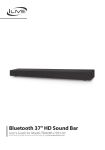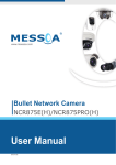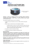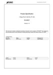
1
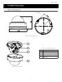
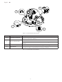
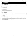
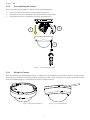
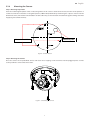
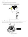
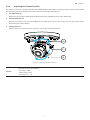
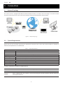
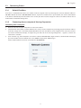
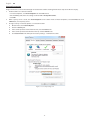
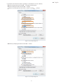
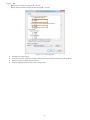
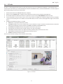
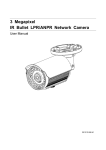
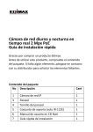
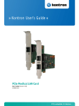
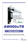
Mini Outdoor Dome Network Camera
NOD316
Quick Start
Guide
201511 316 A1
English
WARNING
••
••
••
••
••
••
••
••
This camera operates at PoE (IEEE 802.3af Class 3) only.
Installation and service should be performed only by qualified and experienced technicians and comply with all local
codes and rules to maintain your warranty.
To reduce the risk of fire or electric shock, do not expose the product to rain or moisture.
Wipe the camera with a dry soft cloth. For tough stains, slightly apply with diluted neutral detergent and wipe with a dry
soft cloth.
Do not apply benzene or thinner to the camera, which may cause the surface to be melted or lens fogged.
Avoid aligning the lens with extremely bright objects (e.g., light fixtures) for long periods of time.
Although this camera is waterproof and suitable for both indoor and outdoor usages, please do not sink the camera into
water. Contact your dealer in case of sunk.
Avoid operating or storing the camera in the following locations:
•• Extremely humid, dusty, or hot/cold environments (recommended operating temperature: -40°C to +50°C)
•• Close to sources of powerful radio or TV transmitters
•• Close to fluorescent lamps or objects with reflections
•• Under unstable or flickering light sources
WEEE (Waste Electrical and Electronic Equipment). Correct disposal of this product (applicable in
the European Union and other European countries with separate collection systems). This product
should be disposed of, at the end of its useful life, as per applicable local laws, regulations, and procedures.
1
English
FCC Compliance Statement
Information to the user: This unit has been tested and found to comply with the limits for a Class B digital
device pursuant to Part 15 of the FCC Rules. Operation is subject to the following two conditions: (1) this
device may not cause harmful interference, and (2) this device must accept any interference received,
including interference that may cause undesired operation. These limits are designed to provide reasonable
protection against harmful interference in a residential installation. This unit generates, uses, and can radiate radio
frequency energy and, if not installed and used in accordance with the manual, may cause harmful interference to radio
communications. However, there is no guarantee that interference will not occur in a particular installation.
If this unit does cause harmful interference to radio or television reception, which can be determined by turning the unit off
and on, the user is encouraged to try to correct the interference by one or more of the following measures:
•• Reorient or relocate the receiving antenna.
•• Increase the separation between the unit and receiver.
•• Connect the unit to an outlet on a circuit different from that to which the receiver is connected.
•• Consult the dealer or an experienced radio/TV technician for help.
Caution
Changes or modifications not expressly approved by the party responsible for compliance could void
the user’s authority to operate the unit.
CE Statement
Operation is subject to the following two conditions: (1) this device may not cause harmful interference, and
(2) this device must accept any interference received, including interference that may cause undesired
operation. The manufacturer declares that the unit supplied with this guide is compliant with the essential
protection requirements of EMC directive and General Product Safety Directive GPSD conforming to
requirements of standards EN55022 for emission, EN 55024 for immunity, EN 300 and EN 328 for WIFI.
2
English
1
Product Overview
1.1
Physical Characteristics
Unit: mm
Figure 1 - 1: Physical Dimension
1
2
Table 1 - 1: Pictorial Index Definition
No
3
4
Figure 1 - 2: Pictorial Index
3
Name
1
Conduit Hole
2
Inner Liner
3
Camera Body
4
Top Cover
English
A
B
C
D
Figure 1 - 3: Internal Interface Pictorial Index
No
Interface
Description
Insert an Ethernet cable into the port for network connection as well as PoE
(Power over Ethernet) capability.
A
RJ-45 Ethernet PoE Port
B
Reset & Default Button
Press the button for 6 seconds to restore the camera’s settings back to the factory
default.
C
Micro SD card slot
Insert a micro SD card into the slot for recording and file storage.
D
Mini USB Port
Connect with USB to RJ-45 adaptor for real time image preview, which is useful
for installer to adjust a desired field of view during installation.
Press the button for below 1 second to reboot the camera.
Table 1 - 2: Internal Interface Index Definition
4
English
2
Installation
2.1
Package Content
Check if everything in the packing box matches to the order form and the packing slip. All items listed below should be
included in the packing box.
•• Network Mini Outdoor Dome Camera x1
•• Printed Quick Guide x1
•• Guide Pattern x1
•• Torx Wrench x1
•• Plastic Anchors x3
•• Tapping Screws x3
Please contact your dealer if any of the items is lost.
2.2
Installation
Following tools might help you complete the installation:
•• a drill
•• screwdrivers
•• wire cutters
2.2.1
Checking Appearance
When first unboxing, please check whether if there is any visible damage to appearance of the camera and its accessories.
The protective materials used for the packaging should be able to protect the camera from most of accidents during
transportation. Please remove the protective materials of the camera when every item is properly checked in accordance
with the list in “Package Content”.
5
English
2.2.2
Disassembling the Camera
Please refer to the steps with figures below for correct disassembling order.
1.
2.
3.
Loosen the 3 torx screws counter-clockwise by the torx wrench.
Gently pull the top cover downward to take it apart from the camera body.
Lift to open the inner liner coating on the lens for adjustment later.
3
2
1
Figure 2 - 1: Disassembling the Camera
2.2.3
Wiring the Camera
After disassembling, the PoE RJ-45 Ethernet port is visible on the camera body for user to connect an Ethernet cable for both
power supply and network connectivity purposes. The Ethernet cable can be arranged by side conduit or bottom conduit
manner. The following figures are for reference on how to arrange 2 methods.
Figure 2 - 2: Bottom Conduit Manner
Figure 2 - 3: Side Conduit Manner
6
English
2.2.4
Mounting the Camera
Step 1. Mounting Preparation
Paste the included guide pattern onto a wall/ceiling where the IP camera is about to be located, and drill 3 hole patterns in
accordance with the indications on the guide pattern (3-Ø4.5 Holes) followed by hammering the 3 plastic anchors into the
drilled holes. Also, drill another hole for button conduit cable entry as the indication of “Cable hole” (Ignore drilling cable hole
if applying side conduit manner).
Cable Entry Hole
Plastic Anchors Holes
Figure 2 - 4: Guide Pattern
Step 2. Mounting the Camera
Place the camera on the predefined surface and fasten the 3 tapping screws clockwise into the plugged plastic anchors
securely to fix the camera onto the location.
Figure 2 - 5: Mounting the Camera
7
English
Step 3. Assembling the Camera
Please refer to the following steps with figure for correct assembling order.
1. After adjustment, fit the inner liner over the camera lens until it clicks into the place.
2. Gently put the top cover upward to attach with the camera body.
3.
Fasten the 3 torx screws with the camera body clockwise to complete the mounting.
2
1
3
Figure 2 - 6: Assembling and Completing Camera Mounting
2.2.5
Desiccant Placement
For the sake of lessening the moisture effects within the camera, it is strongly recommended to have a desiccant pack
adhered to the internal side of the inner liner as shown below prior to completing the mounting procedure.
Desiccant Pack
Figure 2 - 7: Desiccant Placement
8
English
2.2.6
Adjusting the Camera Position
The camera has three axes to adjust field of view for different applications. While screening live view on your monitor, adjust
the axes by the procedures below simultaneously for desired coverage of field of view.
••
Pan Adjustment (A)
Rotate the lens base until satisfied with the field of view. Please DO NOT rotate over the default limit.
••
Horizontal Rotation (B)
Rotate 3D assembly in the lens, but DO NOT turn assembly more than the limit as this may have the internal cables
twisted, disconnected, or broken.
••
Tilt Adjustment (C)
Tilt the camera lens within the certain range (27° - 90°) to your desired field of view.
A
C
B
Figure 2 - 8: Adjusting the Camera Position
Limitation for three axes position:
Caution
•• Pan range : >360°
•• Rotate range : ±175°
•• Tilt range : 27° ~ 90°
9
English
3
Connection
3.1
Network Topology
The camera, which is equipped with Ethernet RJ-45 network interface, can deliver live view image in real time via both
Internet and Intranet manners. Please refer to the skeleton drawings shown below for understanding.
Figure 3 - 1: Network Topology
3.2
System Requirements
Below table lists the minimum requirement to implement and operate the camera. No hardware/software component
inferior to the requirements is recommended.
Table 3 - 1: System Requirements
System Hardware
CPU
RAM
Display
System Software
Operating System
Browser
Unit
Power Supply
Networking
Wired*
Intel Pentium 4 2.4GHz or equivalent
1 GB or above
NVIDIA GeForce 6 Series or ATI Mobility Radeon 9500
Microsoft Windows XP, Windows Vista, Windows 7 or above
Microsoft Internet Explorer 8 ~ 10, Chrome, Firefox, Safari
PoE (IEEE 802.3af Class 3)
10/100BASE-T Ethernet (RJ-45 connector)
*a switch is required for surveillance on multiple cameras.
Note
All the installation and operations should comply with your local electricity safety rules.
Caution
When adopting PoE, this camera is to be connecting only to PoE networks without routing to
heterogeneous devices.
10
English
3.3
Connecting Process
3.3.1
Default IP address
Since this is a network-based camera, an IP address must be assigned at the very first stage. The camera’s default IP address is
192.168.1.30 and sub mask is 255.255.255.0. However, if you have a DHCP server in your network, the camera would obtain
an IP address automatically from the DHCP server so that you don’t need to change the camera’s IP address. But be sure to
enable DHCP in "Network Settings" first.
3.3.2
Connecting from a computer & Viewing Preparation
Connecting from a computer
1.
2.
3.
Make sure the unit and your computer are in the same subnet.
Check whether the network available between the camera and the computer by executing ping the default IP address.
To do this, simply start a command prompt (Windows: from the “Start Menu”, select “Program”. Then select “Accessories”
and choose “Command Prompt”), and type “Ping 192.168.1.30”. If the message “Reply from…” appears, it means the
connection is available.
Start a browser e.g., Internet Explorer and enter IP address: 192.168.1.30. A login window as shown below should pop
up. In the window, enter the default user name: admin and password: 1234 to log in.
Further administration on the unit can be found in “User Manual".
Figure 3 - 2: Login Window
11
English
Viewing Preparation
Images of the unit can be viewed through various browsers. Before viewing, follow these steps to enable the display.
1. Enable Cookies as instructions below
•• In Internet Explorer, click Internet Options on the Tools menu.
•• On the Privacy tab, move the settings slider to Low or Accept All Cookies.
•• Click OK.
2. When a proxy server is used, click Internet Options on the Tools menus of Internet Explorer, select Connect tab, click
LAN button, and set proxy server.
3. Change Security in Internet options as instructions below
●● On tool menu, click Internet Options.
●● Press the Security tab.
●● If the camera operates inside of the intranet, click the Intranet icon.
●● If the camera operates outside of the intranet, click the Internet icon.
●● Click Custom Level. This will open the Security Settings – Internet Zone screen.
Figure 3 - 3: Security Settings 1/4
12
English
•• Scroll down to the ActiveX controls and plug-ins radio buttons and set as follows:
【Download signed ActiveX controls】 → Prompt (recommended)
【Download unsigned ActiveX controls】→ Prompt
【Initialize and script ActiveX not marked as safe for scripting】→ Prompt
Figure 3 - 4: Security Settings 2/4
【Automatic prompting for ActiveX controls】→ Enable
Figure 3 - 5: Security Settings 3/4
13
English
【Run ActiveX controls and plug-ins】→ Enable
【Script ActiveX controls marked safe for scripting*】→ Enable
Figure 3 - 6: Security Settings 4/4
●●
●●
●●
●●
Press OK to save the settings.
Close the all browser windows and restart the browser. This will allow the new settings taking effect.
Type your setting IP address into the browser.
Then you should be able to see the camera image screen.
14
English
3.4
IP Finder
IP Finder is a utility program that helps users to locate the unit in local area network that computer is connected to. Please
note that IP Finder works only in Microsoft Windows XP, Microsoft Windows Vista, and Microsoft Windows 7 or above. Steps to
get the utility program running are listed below.
1.
2.
3.
4.
5.
Download IP Finder from MESSOA Website to computer.
Double click on IPFinder.exe in computer’s IP Finder folder, and the IP Finder window should pop out.
The window would list information of units in operation at present. Press FIND CAMERA to find more units.
Locate and double-click one of the cameras in the list you want to configure the network settings. If you have multiple
cameras connected to your local network, locate the MAC address on the camera to distinguish the target camera from
others.
Configure the following settings as needed.
●● NAME: Enter a descriptive name for the camera.
●● NETWORK SETTINGS: If you have a DHCP server on your network to assign IP addresses to network devices, enable the
DHCP option. Otherwise, manually enter the IP ADDRESS, NET MASK and GATEWAY values.
●● USERNAME & PASSWORD: Manually setup preferred username and password.
●● SET: Whenever you make revision of camera settings, click “SET” to take effect.
●● SW DEFAULT: To perform the factory defaults excluding network settings of the selected camera.
●● HW DEFAULT: To perform the factory defaults of the selected camera.
●● REBOOT: To reboot the selected camera.
Click Save to enable the settings and click Exit to exit the utility.
Figure 3 - 7: IP Finder
15