1
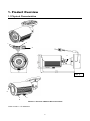
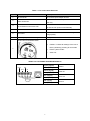
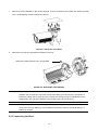
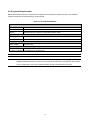
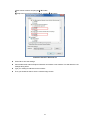
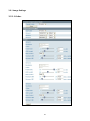
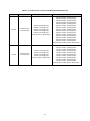
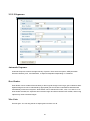
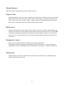
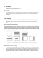
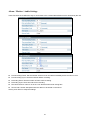
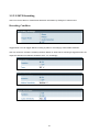
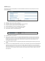
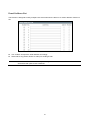
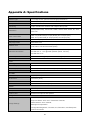
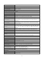
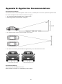
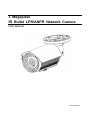
3 Megapixel IR Bullet LPR/ANPR Network Camera User Manual 201312 606 A1 NOTICE Please read this manual thoroughly and save it for future use before attempting to connect or operate this unit. 1 Table of Content FCC Compliance Statement .............................................................................................................4 CE Statement ........................................................................................................................................4 Preface ............................................................................................................................................................. 5 1. Product Overview .................................................................................................................................... 6 1.1 Physical Characteristics .......................................................................................................................6 2. Installation and Connection ................................................................................................................ 9 2.1 Unpack Everything ...............................................................................................................................9 2.2 Installation ............................................................................................................................................9 2.2.1 Checking Appearance .............................................................................................................. 9 2.2.2 Mounting the camera ............................................................................................................... 9 2.2.3 Connecting the Wires ............................................................................................................. 10 2.2.4 Adjusting the Camera Position ............................................................................................... 11 2.2.5 Adjusting the zoom & focus (vari-focal) / default & reset button ............................................ 12 2.2.6 Adjusting the Sun shield hood ................................................................................................ 12 2.2.7 Network Topology ................................................................................................................... 13 2.2.8 System Requirements ............................................................................................................ 14 2.3 Connection ........................................................................................................................................ 15 2.3.1 Default IP address .................................................................................................................. 15 2.3.2 Connecting from a computer & Viewing Preparation ............................................................. 15 2.4 IP Finder ............................................................................................................................................ 19 3. Administration and Configuration ................................................................................................... 20 3.1 Live View ........................................................................................................................................... 20 3.2 Configuration ..................................................................................................................................... 21 3.2.1 Image Settings ....................................................................................................................... 22 3.2.2 Network Settings .................................................................................................................... 34 3.2.3 System Settings ..................................................................................................................... 42 3.2.4 Event Settings ........................................................................................................................ 49 Appendix A: Specifications..................................................................................................................... 58 Appendix B: Application Recommendations .................................................................................... 61 2 WARNING This unit operates at AC 24V/ PoE. Installation and service should be performed only by qualified and experienced technicians and comply with all local codes and rules to maintain your warranty. To reduce the risk of fire or electric shock, do not expose the product to rain or moisture. Wipe the camera with a dry soft cloth. For tough stains, slightly apply with diluted neutral detergent and wipe with a dry soft cloth. Do not apply benzene or thinner to the camera, which may cause the surface of the unit to be melted or lens to be fogged. Avoid aligning the lens to very bright objects (example, light fixtures) for long periods of time. Avoid operating or storing the unit in the following locations: Extremely humid, dusty, or hot/cold environments (recommended operating temperature: -40℃ to +50℃) Close to sources of powerful radio or TV transmitters Close to fluorescent lamps or objects with reflections Under unstable or flickering light sources WEEE (Waste Electrical and Electronic Equipment). Correct disposal of this product (applicable in the European Union and other European countries with separate collection systems). This product should be disposed of, at the end of its useful life, as per applicable local laws, regulations, and procedures. 3 FCC Compliance Statement Information to the user: This unit has been tested and found to comply with the limits for a Class B digital device pursuant to Part 15B of the FCC Rules. Operation is subject to the following two conditions: (1) this device may not cause harmful interference, and (2) this device must accept any interference received, including interference that may cause undesired operation. These limits are designed to provide reasonable protection against harmful interference in a residential installation. This unit generates, uses, and can radiate radio frequency energy and, if not installed and used in accordance with the manual, may cause harmful interference to radio communications. However, there is no guarantee that interference will not occur in a particular installation. If this unit does cause harmful interference to radio or television reception, which can be determined by turning the unit off and on, the user is encouraged to try to correct the interference. For example, try reorienting or relocating the receiving antenna, increasing the separation between the unit and receiver, or connecting the unit to an outlet on a different circuit. Caution Changes or modifications not expressly approved by the party responsible for compliance could void the user’s authority to operate the unit. CE Statement Operation is subject to the following two conditions: (1) this device may not cause harmful interference, and (2) this device must accept any interference received, including interference that may cause undesired operation. The manufacturer declares that the unit supplied with this guide is compliant with the essential protection requirements of EMC directive and General Product Safety Directive (GPSD) conforming to requirements of standards EN55022 for emission, EN 55024 for immunity. 4 Preface This user manual is designed as a reference for the installation and manipulations of the unit including the camera’s features, functions, and detailed explanation of the menu tree. The reader is supposed to be able to get following information in the manual. Product Overview: the main functions and system requirements of the unit. Installation and Connection: instructions on unit installation and wire connections. Administration and Configuration: the main menu navigation and controls explanations. 5 1. Product Overview 1.1 Physical Characteristics 2 1 3 4 Unit: ㎜ 5 7 6 FIGURE 1-1: PHYSICAL DIMENSION & PICTORIAL INDEX* *Refer to table 1-1 for definitions 6 TABLE 1-1: PICTORIAL INDEX DEFINITION Index # Name Description 1 I/O Connector To connect Input/ Output devices 2 Power Connector 3 24V only To insert the RJ-45 cable for network connection RJ-45 Ethernet Connector/ PoE 4 Mount bracket 5 Sun shield 6 Connects to the external power source at AC as well as PoE (Power over Ethernet) To connects the Mount. To minimize the effects of rain and sunlight on image quality. Externally adjustable focal length & focus To adjust the Near/Far and Tele/Wide controls Reset button and Default button a. Default: To Reset all settings of the unit to factory default by pressing for 5 seconds 7 b. Reset: system restart c. Video out TABLE 1-2: I/O CONNECTOR DEFINITIONS 1/2 Purple (Signal) Au/O Au/I AO Green (GND) AI Yellow (Signal) Orange (GND) Blue (Signal) Brown (COM) Red (Signal) Black (GND) 7 Audio in Audio out Alarm out Alarm in TABLE 1-3: PIN DEFINITIONS 2/2 Return to factory default by press button Default for 5 seconds Reset System restart Video Out Caution To output video signal When rotated the knob to remove the default/reset cover, please tighten the screw to avoid water leaking after adjustment. Note Connectors and field wiring terminals for external Class 2 circuits provided with marking indicating minimum Class of wiring to be used. Class 2 shall be marked adjacent to the field wiring terminals. 8 2. Installation and Connection 2.1 Unpack Everything Check everything in the packing box matches to the order form and the packing slip. In addition to this manual, items below are included in the packing box. One IR Bullet LPR/ANPR Network Camera One 2-pin terminal block for power input One printed quick installation guide One monitor out cable One mounting template Six screw anchors Six screws Please contact your dealer if any item missing. 2.2 Installation Following tools might help you complete the installation: a drill screwdrivers wire cutters 2.2.1 Checking Appearance When first unboxing, please check whether if there is any visible damage to appearance of the unit and its accessories. The protective materials used for the packaging should be able to protect the unit from most of accidents during transportation. Please remove the protective part of the unit when every item is checked in accordance with the list in 2.1 Unpacking Everything. 2.2.2 Mounting the camera 9 1. Affix the mounting template to the desired location, knock in 6 plastic anchors after hole drilling and then lock in 6 self-tapping screws to fasten the camera. FIGURE 2-1: MOUNTING THE CAMERA 2. Mount the unit onto the ceiling/wall and fasten it securely. Safety wire (fall prevention wire, not supplied) FIGURE 2-2: MOUNTING THE CAMERA Warning Depending on the material of mounting surface, different screws and anchors than those supplied may be required. To prevent the unit from falling off, ensure that it is mounted to a firm place (ceiling slab or channel) using a safety wire strong enough to withstand the total weight of the unit. (Pay also attention to the finishing at the end of the wire.) Caution Safety wire must be connected with one end the wall/ceiling and the other to the safety-cord screw of the unit. By cabling so, it is possible to prevent the unit from accidental falling in a sudden at any time. 2.2.3 Connecting the Wires 10 1. To attach the camera to the fixed place. FIGURE 2-3: CONNECTING THE WIRES 2. Pass all the signal cables through the mounting bracket as the sample photo shown. 3. Connect the power cable to the power plugs with one of the following options. AC 24V: Connect 24V (~) cables to terminals ~AC 24V PoE: Connect the RJ-45 jack to a PoE compatible network device that supplied power through the Ethernet cable 4. Insert audio cable and alarm cable to the unit, and connect the network cable to the RJ-45 terminal of a switch. FIGURE 2-4: CONNECTING THE WIRES 2.2.4 Adjusting the Camera Position 11 1. Use the cross screwdriver loosen the cross screw on one side of the mount bracket so that you can tilt the camera. 2. Loosen the screw on the retaining ring to adjust the camera angle. 3. After adjustments, fasten the screws and retaining ring back to the camera. Retaining ring Cross screw FIGURE 2-5: ADJUSTING THE CAMERA POSITION 2.2.5 Adjusting the zoom & focus (vari-focal) / default & reset button 1. Use a screwdriver to adjust the Near/Far and Tele/Wide controls. Please be careful when adjusting Near/Far and Tele/Wide so as to avoid damage to the lens. 2. Use a flat head screwdriver to open the cover, then user can press default button to factory setting or reset button to reboot system. Tele/Wide control Near/Far control Default/Reset (inside) FIGURE 2-6: ADJUSTING THE ZOOM & FOCUS (VARI-FOCAL) Caution After ajustment, tighten the screws to avoid water leaking issue. 2.2.6 Adjusting the Sun shield hood 12 Move the sunshield hood forward and backward to adjust the position of sunshade. Caution Be sure to adjust the sunshield hood in coordination with lens in case of sunshade problems. Don’t adjust the sun shield position excessively to avoid housing damaged. FIGURE 2-7: ADJUSTING THE SUN SHIELD HOOD 2.2.7 Network Topology The camera can deliver video images and audio in real time using the Internet and Intranet. It's equipped with Ethernet RJ-45 network interface. FIGURE 2-8: NETWORK TOPOLOGY TYPEⅠ FIGURE 2-9: NETWORK TOPOLOGY TYPEⅡ 13 2.2.8 System Requirements Below table lists the minimum requirement to implement and operate the network camera. No hardware/ software component underestimated is recommended. TABLE 2-1: SYSTEM REQUIREMENTS System Hardware CPU Intel Pentium 4 2.4GHz or equivalent RAM 1 GB or above Display NVIDIA GeForce 6 Series or ATI Mobility Radeon 9500 System Software Operating System Microsoft Windows XP, Windows Vista, or Windows 7 Browser Microsoft Internet Explorer 8 or above Unit Power Supply AC 24V / PoE Networking Wired* 10/100BASE-T Ethernet (RJ-45 connector) *a switch is required for surveillance on multiple units. Note All the installation and operations should comply with your local electricity safety rules. Caution To avoid damage to the unit, never connect more than one type of power supply (PoE IEEE802.3 Ethernet Class 0 or AC24V power plug) at the same time. If using PoE, this camera is to be connecting only to PoE networks without routing to heterogeneous devices. 14 2.3 Connection 2.3.1 Default IP address Since this is a network-based unit, an IP address must be assigned at the very first. The unit’s default IP address is 192.168.1.30 and sub mask is 255.255.255.0. However, if you have a DHCP server in your network, the unit would obtain an IP address automatically from the DHCP server so that you don’t need to change the camera’s IP address. But be sure to enable DHCP in "Network/Basic settings". 2.3.2 Connecting from a computer & Viewing Preparation 2.3.2.1 Connecting from a computer 1. Make sure the unit and your computer are in the same subnet. 2. Check whether if the networking available between the unit and the computer by executing ping the default IP address. To do this, simply start a command prompt (Windows: from the Start Menu, select Program. Then select Accessories and choose Command Prompt.), and type “Ping 192.168.0.30”. If the message “Reply from…” appears, it means the connection is available. 3. Start Internet Explorer and enter IP address: 192.168.1.30. A login window should pop up. In the window, enter the default user name: admin and password: 1234 to log in. Further administration on the unit can be found in “3. Administration and Configuration". FIGURE 2-4: LOGIN WINDOW 15 2.3.2.2 Viewing Preparation Images of the unit can be viewed through Microsoft Internet Explorer 8 or above. Before viewing, follow these steps to enable the display. 1. 2. Enable Cookies as instructions below In Internet Explorer, click Internet Options on the Tools menu. On the Privacy tab, move the settings slider to Low or Accept All Cookies. Click OK. When a proxy server is used, click Internet Options on the Tools menus of Internet Explorer, select Connect tab, click LAN button, and set proxy server. 3. Change Security in Internet options as instructions below On tool menu, click Internet Option. Press the Security tab. If the camera operates inside of the intranet, click the Intranet icon. If the camera operates outside of the intranet, click the Internet icon. Click Custom Level. This will open the Security Settings – Internet Zone screen. FIGURE 2-5: SECURITY SETTINGS 1/4 16 Scroll down to the ActiveX controls and plug-ins radio buttons and set as follows: 【Download signed ActiveX controls】 Prompt (recommended) 【Download unsigned ActiveX controls】 Prompt 【Initialize and script ActiveX not marked as safe for scripting】 Prompt FIGURE 2-5: SECURITY SETTINGS 2/4 【Automatic prompting for ActiveX controls】 Enable FIGURE 2-5: SECURITY SETTINGS 3/4 17 【Run ActiveX controls and plug-ins】 Enable 【Script ActiveX controls marked safe for scripting*】 Enable FIGURE 2-5: SECURITY SETTINGS 4/4 Press OK to save the settings. Close all Microsoft Internet Explorer Windows and restart a new window. This will allow the new settings taking effect. Type your setting IP address into the browser. Then you should be able to see the camera image screen. 18 2.4 IP Finder IP Finder is a utility program that helps users to locate the unit in local area network that computer is connected to. Please note that IP Finder works only in Microsoft Windows XP, Microsoft Windows Vista, and Microsoft Windows 7. Steps to get the utility program running are listed below. 1. Download IP Finder from MESSOA website and save it to computer. 2. Double click on IpFinder.exe in computer’s IP Finder folder, and the IP Finder window should pop out. 3. The window would list information of units in operation at present. Press Search to find more units. 4. Locate and double-click the camera you want to configure the network settings. If you have multiple cameras connected to your local network, locate the MAC address on the camera to distinguish the target camera from others. 5. Configure the following settings as needed. Name: Enter a descriptive name for the camera. Network Setting: If you have a DHCP server on your network to assign IP addresses to network devices, enable the DHCP option. Otherwise, manually enter the IP, Subnet Mask and Gateway settings. Click Save to enable the settings and click Exit to exit the utility. FIGURE 2-6 IP CAMERA FINDER* *Actual screen may vary depending on the version of the utility. 19 3. Administration and Configuration 3.1 Live View Simply click on Live View on the top left side of the browser window while accessing the IP address of the unit, and a live video is displayed directly in the browser window. When clicked on Configuration, a window will be pop out for configuring “Image”, “Network”, “System”, “Event”, and “Record”. Please refer to 3.2 Configuration for more information. The current logged in identity shows next right. If clicked on Logout, this window of administration and configuration will be closed. Followings are explanations to the live view window. Snapshot: Take a picture from live view. e-PTZ: After you click the ePTZ button, an ePTZ control panel will shows up where you can click the corresponding indicators to perform desired operations:: • To zoom in/out: Click the +/- indicator repeatedly to zoom in/out the live view image. • To pan left/right: Click the left/right indicator to pan the viewing area. The pan function does not work if the video is not zoomed-in (no zoom status). • To tilt up/down: Click the up/down indicator to tilt the viewing area. The tilt function does not work if the video is not zoomed-in (no zoom status). • To preset to home: Click the home indicator and the image will return to the original view. : Alarm Indicator: Appears when an alarm is triggered. : Recording Indicator: Turns red when the recording is proceeding. * When the resolution is set to 2048x1536 or 2304x1296, only one single streaming is available. 20 3.2 Configuration When clicked on Setup, a window will be pop out for configuring “Image”, “Network”, “System”, “Event”, and “Record”. 21 3.2.1 Image Settings 3.2.1.1 Codec 22 Edit Profile This unit offers two choices of video codecs for real-time viewing: H.264 or M-JPEG. Click codec to change desired setting as below. By default, there are 6 compression profiles can be chose for respective resolution, frame rate, and picture quality as required. Be sure to click save to keep the desired setting. TABLE 3-1: EDIT PROFILE OPTIONS Item Video Codec Option Description M-JPEG/H.264 Set a default codec While 2048×1536 or 2304×1296 is the highest resolution, CIF 2048×1536 is the lowest resolution. 2304×1296 supports H.264 only. 2304×1296 1080P(1920×1080) SXGA(1280×960) 720P(1280×720) Resolution SVGA(800×600) D1(720×480) 4CIF(704×480) VGA(640×480) CIF(352×240) Frame rate is based on second. PAL: H.264 or M-JPEG single stream:2048×1536; H.264 single stream: 2304×1296, 1080P(1920×1080)@25fps, PAL: 1~25 3M(2048×1536)@12fps Frame Rate NTSC: 1~30 NTSC: H.264 or M-JPEG single stream: 2048×1536; H. 264 single stream:2304×1296, 1080P(1920×1080)@30fps, 3M(2048×1536)@15fps Choose the bit rate control selection based on user Bit Rate Mode Variable Bit Rate/Constant Bit Rate requirements. A higher bit rate will use higher network bandwidth Select the GOP (Group of pictures) number from 1 to 60. Recovery of the lost frames will be more difficult as the GOP 1-60 number gets bigger; on the contrary, it will increase the bite rate obviously and aggravate the network bandwidth. The default value is 30. GOP will be differed by frame rate setting. 23 TABLE 3-2: CORRELATIONS OF RESOLUTION/STREAMS/FPS/CODECS 1/2 Resolution Single stream Double stream Triple stream 2048×1536 2048×1536 @ 15fps (H.264/M-JPEG) N/A N/A 2304×1296 2304×1296 @ 15fps (H.264) N/A N/A 1920×1080 1920×1080 @ 30fps (H.264*/M-JPEG) 1920x1080, 720x480 @ 30fps* 1920x1080, 640x480 @ 30fps* 1920x1080, 352x240 @ 30fps* (H.264*, H.264/M-JPEG*) 1920x1080, 352x240, 352x240 @ 30fps (H.264, H.264/M-JPEG, H.264/M-JPEG) 1280x960, 1280x720 @ 30fps 1280x960, 800x600 @ 30fps 1280x960, 720x480 @ 30fps 1280x960, 704x480 @ 30fps 1280x960, 640x480 @ 30fps 1280x960, 352x240 @ 30fps (H.264/M-JPEG, H.264/M-JPEG) 1280x960, 1280x720, 352x240 @ 30fps 1280x960, 800x600, 800x600 @ 30fps 1280x960, 800x600, 720x480 @ 30fps 1280x960, 800x600, 704x480 @ 30fps 1280x960, 800x600, 640x480 @ 30fps 1280x960, 800x600, 352x240 @ 30fps 1280x960, 720x480, 720x480 @ 30fps 1280x960, 720x480, 704x480 @ 30fps 1280x960, 720x480, 640x480 @ 30fps 1280x960, 720x480, 352x240 @ 30fps 1280x960, 704x480, 704x480 @ 30fps 1280x960, 704x480, 640x480 @ 30fps 1280x960, 704x480, 352x240 @ 30fps 1280x960, 640x480, 640x480 @ 30fps 1280x960, 640x480, 352x240 @ 30fps 1280x960, 352x240, 352x240 @ 30fps (H.264/M-JPEG, H.264/M-JPEG, H.264/M-JPEG) 1280x720, 1280x720 @ 30fps** 1280x720, 800x600 @ 30fps 1280x720, 720x480 @ 30fps 1280x720, 704x480 @ 30fps 1280x720, 640x480 @ 30fps 1280x720, 352x240 @ 30fps** (H.264**/M-JPEG, H.264/M-JPEG**) 1280x720, 1280x720, 800x600 @ 30fps 1280x720, 1280x720, 720x480 @ 30fps 1280x720, 1280x720, 704x480 @ 30fps 1280x720, 1280x720, 640x480 @ 30fps 1280x720, 1280x720, 352x240 @ 30fps 1280x720, 800x600, 800x600 @ 30fps 1280x720, 800x600, 720x480 @ 30fps 1280x720, 800x600, 704x480 @ 30fps 1280x720, 800x600, 640x480 @ 30fps 1280x720, 800x600, 352x240 @ 30fps 1280x720, 720x480, 720x480 @ 30fps 1280x720, 720x480, 704x480 @ 30fps 1280x720, 720x480, 640x480 @ 30fps 1280x720, 720x480, 352x240 @ 30fps 1280x720, 704x480, 704x480 @ 30fps 1280x720, 704x480, 640x480 @ 30fps 1280x720, 704x480, 352x240 @ 30fps 1280x720, 640x480, 640x480 @ 30fps 1280x720, 640x480, 352x240 @ 30fps** 1280x720, 352x240, 352x240 @ 30fps (H.264**/M-JPEG, H.264/M-JPEG**, H.264**/M-JPEG) 1280×960 1280×720 1280×960 @ 30fps (H.264/M-JPEG) 1280×720 @ 30fps (H.264/M-JPEG) *Profile 1, 2, & 3 defaults. **Profile 4, 5, & 6 defaults. 24 TABLE 3-3: CORRELATIONS OF RESOLUTION/STREAMS/FPS/CODECS 2/2 Resolution 800×600 720×480 Single stream 800×600 @ 30fps (H.264/M-JPEG) 720×480 @ 30fps (H.264/M-JPEG) Double stream Triple stream 800x600, 800x600 @ 30fps 800x600, 720x480 @ 30fps 800x600, 704x480 @ 30fps 800x600, 640x480 @ 30fps 800x600, 352x240 @ 30fps (H.264/M-JPEG, H.264/M-JPEG) 800x600, 800x600, 800x600 @ 30fps 800x600, 800x600, 720x480 @ 30fps 800x600, 800x600, 704x480 @ 30fps 800x600, 800x600, 640x480 @ 30fps 800x600, 800x600, 352x240 @ 30fps 800x600, 720x480, 720x480 @ 30fps 800x600, 720x480, 704x480 @ 30fps 800x600, 720x480, 640x480 @ 30fps 800x600, 720x480, 352x240 @ 30fps 800x600, 704x480, 704x480 @ 30fps 800x600, 704x480, 640x480 @ 30fps 800x600, 704x480, 352x240 @ 30fps 800x600, 640x480, 640x480 @ 30fps 800x600, 640x480, 352x240 @ 30fps 800x600, 352x240, 352x240 @ 30fps (H.264/M-JPEG, H.264/M-JPEG, H.264/M-JPEG) 720x480, 720x480 @ 30fps 720x480, 704x480 @ 30fps 720x480, 640x480 @ 30fps 720x480, 352x240 @ 30fps (H.264/M-JPEG, H.264/M-JPEG) 720x480, 720x480, 720x480 @ 30fps 720x480, 720x480, 704x480 @ 30fps 720x480, 720x480, 640x480 @ 30fps 720x480, 720x480, 352x240 @ 30fps 720x480, 704x480, 704x480 @ 30fps 720x480, 704x480, 640x480 @ 30fps 720x480, 704x480, 352x240 @ 30fps 720x480, 640x480, 640x480 @ 30fps 720x480, 640x480, 352x240 @ 30fps 720x480, 352x240, 352x240 @ 30fps (H.264/M-JPEG, H.264/M-JPEG, H.264/M-JPEG) 25 3.2.1.2 Exposure Automatic Exposure Automatic Exposure controls the light intensity of picture. There are three options, AES (Automatic Electronic Shutter), ALC, and Flickerless, to adjust for adjustment depending on conditions. Slow Shutter Slow Shutter can be enabled if the sensitivity is still not good enough under “High” gain condition at dark. Optimal image level can be maintained by appropriate gain and shutter combination that determined automatically inside the unit system. Slow Shutter can be selected from OFF, 1/30, 1/15, and 1/7.5. As slow shutter activates, the exposure time becomes longer and frame rate becomes smaller, and moving objects may result in blurred images. Max Gain Set max gain. You can drag the bar to adjust gain level from 0 to 36. 26 Manual Exposure Select this option to manually define exposure values of the unit. Exposure Time Set desired Exposure Time from 1/60s to 1/8000s. When broadcast TV system is set to PAL, the Shutter Speed can be set at 1/50, 1/100, 1/250, 1/500, 1/1000, 1/2000, 1/4000, or 1/8000s; when NTSC, 1/60, 1/120, 1/250, 1/500, 1/1000, 1/2000, 1/4000, or 1/8000s. The unit will adjust the aperture according to the amount of ambient light. Selecting 1/8000s provides the dark image. IRIS Control Adjust the DC IRIS opening level until the image is neither too bright nor too dark. Select Open to open the IRIS to its maximum or select Close to close the IRIS so that no light is let into the lens. When Auto is selected, the IRIS will automatically compensate according to the light conditions. Level can be set from level 1 to 8. The higher the level, the more possible the IRIS will open so that the more light is let into the lens. Illumination Control Specify the IR illuminator behavior according to the installation applications. When Auto is selected, the light sensor automatically turns the illuminator on or off according to the ambient light conditions. Select ON to enforce the illuminator to be always on or OFF to be always off. Manual Gain Set Manual Gain value from 0 to 36dB. This function applies to manual lens only. 36dB brightens the image and 0dB darkens the image. 27 EV Adjustment EV Adjustment can be set between 2.0 to -2.0. Day / Night To set DAY/NIGHT function, simply move the cursor to select Auto, Color, or BW mode. If Color selected, the unit is forced to stay in COLOR mode all day. If BW selected, the unit is forced to stay in NIGHT mode all day. Noise Reduction Noise reduction is the process of removing noise from signal. Users can configure the noise reduction related setting 0~255 to reduce noise on the screen. Selecting 255 provides the best image without noise. BLC (Backlight Compensation) Set an area for Backlight Compensation. Backlight Compensation is a function that achieves the brightness of a selected area to optimal image level. This function is necessary when an auto iris lens tends to close due to an intense light coming from back of object in the area wished to view so that the area is too dark and difficult to see. In this case, users may set the area correspond to the portion wished to see. The area size illustrations are roughly as follows. WDR (Wide Dynamic Range) It is intended to provide clear images even under backlight circumstances where intensity of illumination can vary excessively namely where there are both very bright and very dark areas simultaneously in the field of view. WDR enables the capture and display of both bright and dark areas in the same frame, in a way that there are details in both areas, i.e. bright areas are not saturated, and dark areas are not too dark. 28 Please click “Save” button to save your settings. Users can also click “Reset to Default” to set Note all the data and options back to defaults. 3.2.1.3 White Balance White Balance controls color on the screen. Mode can be set to Auto (default) or Manual mode. The color temperature range is 2800°K ~ 8500°K. Set manual gain value of R Gain, G Gain, & B Gain from level 0 to 255. The red (R) gain is used to adjust the color red in the viewing image. It allows adjusting red gain manually according to user requirement ranging from level 0 to 255. The green (G) gin is used to adjust the color of green in the viewing image. It allows adjusting green gain manually according to user requirement ranging from level to 255. The blue (B) gain is used to adjust the color of blue in the viewing image. It allows adjusting blue gain manually according to user requirement ranging from level 0 to 255. 3.2.1.4 Basic Color Brightness adjustment Set picture brightness from level -255 to 255. Selecting 255 provides brightest the image. Contrast Set picture contrast from level 0 to 255. Selecting 255 provides highest contrast. Hue Set picture hue from level -15~15. Selecting 15 provides the deep hue. 29 Saturation Saturation describes the difference of a color from the gray of the same lightness. Increasing saturation deepens the colors of your images, making reds redder and blues bluer. Users can adjust picture saturation level from 0 to 255. Decreasing saturation brings the image closer to a grayscale (that is, monochrome or black-and-white) image. Selecting 255 provides highest image saturation. Sharpness Increasing the sharpness value will sharpen the edges and small feature of viewing images. If the edges appear too smooth or blurred, increase the sharpness; otherwise, decrease the sharpness. Sharpness value can be set from 0 to 15. Selecting 15 provides the sharpest image. Gamma Correction Set gamma correction. You can select “1” or “0.45”. Flip Mirror Set image to be left or right, upside or down and both. Select “OFF”, “Flip”, “Mirror” or” Both” to activate or deactivate the mirror function. Note Please click “Save” button to save your settings. Users can also click “Reset to Default” to set all the data and options back to defaults. 30 3.2.1.5 Privacy Zone 31 Privacy Color Setting Users can select a desire color for the privacy zone color. Privacy Zone Setting Enable button “ON”, then to start mask setting. Use mouse to drag a mask rectangle on the screen, click “Save Zone” to complete the selection. To cancel the mask setting simply clicks “Delete Zone”. Note At max 8 masks can be set on the screen. Caution The privacy zone area is a factor increased by 16. That implies we have to round the length and width of the privacy zone to meet this rule. After rounding the algorithm, the result of privacy zone will be plus or minus 16% of the user selected area. 32 3.2.1.6 ROI On the ROI page you can specify a specific region of the video as more important, i.e., a region of interest (ROI). When a ROI is specified, the camera will assign a higher number of bits to the ROI area to deliver better video quality than non-ROI areas. Function: Select “ON” or “OFF” to use this function. Set ROI Area: Set the desired area of interest by dragging the mouse. 33 3.2.2 Network Settings Below explains how to configure a wired network connection for the unit. Camera Name: Enter a desired camera name or use the default name. DHCP: If selected, the unit will automatically obtain an available dynamic IP address from the DHCP server each time it connects to the LAN. IP Address: Manually input IP address when DHCP off selected. Subnet Mask: Please use default number: 255.255.255.0. If the subnet mask is not properly configured, the unit may not be able to communicate with other devices on the network. Default Gateway: Leave blank as default setting. It is not necessary to enter Default Gateway if it is not used. Ask your Network Administrator for Default Gateway information. Primary DNS: (same as above) Secondary DNS: (same as above) UPnP: When set to “ON”, the unit can be detected automatically by any computer in the LAN to skip the installation of the IP Finder utility. OSD: When set to “ON”, the camera name can be show on the screen. 34 3.2.2.1 FTP In this page, users can activate a FTP Server for recordings. Enter a user name if activated the FTP function. Enter a password associated with the user name. Re-enter the password to confirm it. Determine the number of maximum connections by key-in a number in the Max Simultaneous Connections field. Note: This is the maximum of FTP Client connections, not the maximum of IE Window’s connections. Simply click “OFF” to disable the FTP function. Simply click “ON” to activate the FTP function, and follow the following procedures to set up related settings. To log on the FTP, simply enter ftp://<Login ID>:<Password>@<ip address> in the location field of Microsoft’s Internet Explorer and the recordings will be shown up. The default setting is ftp://admin:[email protected]. Refer to the names of file and the folder for date and time of recordings. Note Please click “Save” button to save your settings. Users can also click “Reset to Default” to set all the data and options back to defaults. 35 3.2.2.2 RTSP To enable RTSP, simply enter the User Name, Password and then select “ON” in Authentication. Transfer Type: Select Multicast or unitcast. URL: Enter the server URL or the stream name. Multicast Address The IP address for multicasting ought to be from 224.0.1.1 to 239.255.255.254. After desired options and values are chosen, please be remembered to click “save” button to save all settings. Note: RTSP URLs for RTSP Stream 1, RTSP Stream 2, and RTSP Stream3 are: rtsp://(ip address)/(stream 1), rtsp://(ip address)/(stream 2), rtsp://(ip address)/(stream 3) respectively. For example: rtsp://192.168.1.30/stream1 Metadata Metadata plays a significant role for media applications especially for ONVIF compatible NVR. Turn on the metadata option and there will be an additional track in the RTSP connection response 36 message. The additional track name is “vnd.onvif” and this track is for event data transmission. Once if the event(motion, alarm) is triggered, RTSP server will transmit event data to RTSP client(usually NVR). RTSP client can receive these data and analyze them. The event data usually includes event trigger time, coordinate…etc. 3.2.2.3 SNMP SNMP (Simple Network Management Protocol) is an Internet standard protocol on top of application layer that restructures the exchange of management information among network-attached nodes, which helps administrators to remotely manage network devices and master network problems with ease. 37 SNMP V1: Tick “ON” or “OFF” to enable or disable. SNMP V2: Tick “ON” or “OFF” to enable or disable. SNMP V3: Tick “ON” or “OFF” to enable or disable. Enter password corresponding to User Name. SNMPv3 provided more security features to SNMP. Read/Write Community String: Enter the names of Read Community and Write Community. Trap: Tick “ON” or “OFF” to enable or disable. Input IP address of Trap Host. Heartbeat: Tick “ON” or “OFF” to enable or disable. Input IP address & Interval of Heartbeat Host & Heartbeat. Download: Click “Download” to get specifics of MIB (Management Information Base). MIBs describe the structure of the management data of a device subsystem; they use a hierarchical namespace containing object identifiers (OID). Each OID identifies a variable that can be read or set via SNMP. Note Please click “Save” button to save your settings. Users can also click “Reset to Default” to set all the data and options back to defaults. 3.2.2.4 DDNS DDNS (Dynamic Domain Name Service) is a service that allows the mapping of a DNS to a dynamic IP address. This allows your network camera to have a fixed domain name even it is assigned with a dynamic IP address by DHCP server. Before using this function, you have to apply for an account and register your host name from DDNS provider. To use DDNS function, a DDNS provider is required. The IP camera provides two free DDNS providers to choose from, “no-ip” and “ChangeIP”. Before using this function, make sure to visit the website of either provider and apply for an account and register your host name. Function: Tick “ON” or “OFF” to enable or disable DDNS function. 38 DDNS Server: Select a free DDNS provider that you registered with. Host name: Enter the hostname that you created with the DDNS provider. User Name/Password: Enter the user name and password of the account that you created with the DDNS provider. 39 3.2.2.5 PPPoE If your IP camera is connected to the Internet using PPPoE, please use this section to configure the settings. PPPoE is a typical connection method used by xDSL or cable modem connection. Before using this function, you have to obtain the PPPoE account information from your ISP. Function: Tick “ON” or “OFF” to enable or disable PPPoE function. User Name/Password: Enter the user name and password of your PPPoE account. 3.2.2.6 802.1x If your local area network is using 802.1x authentication to enhance the security, then all the network devices must get authorized by an authentication server (typically a RADIUS server) for communication. The authentication is usually done by a certificate and authentication protocol. To complete the 802.1x settings, you must obtain required information and apply for a digital certificate from a MIS of your company. . 40 Function: Tick “ON” or “OFF” to enable or disable 802.1x function. User Name/Password: Enter the user name and password that authenticate the IP camera to the network. EAPOL Version: Select the EAP over LAN version as used in your 802.1x–RADIUS server. EAP method: Select the EAP method as used in your 802.1x–RADIUS server. Click Apply to enable the settings. CA certificate: Click Browse and locate the certificate file and then click Upload. 3.2.2.7 Bonjour If your IP camera is to be accessed by Macintosh computer (Max OS) that supports Bonjour protocol, please enable the Bonjour function. Function: Tick “ON” or “OFF” to enable or disable the Bonjour function. 41 3.2.3 System Settings 3.2.3.1 Date & Time Synchronization Mode Synchronization supports three different modes: Set Manual, Synchronize with Computer Clock, and Synchronize with NTP Server. Set manual: Set up the date and time of the unit in the Date and Time field manually. Synchronize with Computer Clock: Select this one to synchronize the date and time of the unit with the computer clock. Synchronize with NTP Server: Select NTP in the Synchronization Mode to synchronize the date and time with the dedicated NTP Server: Input IP address or URL of the dedicated NTP server. Note: Please make sure disable SD recording function before you enable NTP synchronization mode. NTP Synchronize Period: Select interval to synchronize with the NTP server. NTP Time Adjustment Test: Press the button to test synchronization with the dedicated NTP server. 42 DST Time Zone: Select the time difference between Greenwich Mean Time and where the unit is located. Daylight Saving: Tick “Daylight Saving” to enable the daylight-saving function if in a daylight saving time zone (effective in NTP mode only). Note Please click “Save” button to save your settings. Users can also click “Reset to Default” to set all the data and options back to defaults. 43 3.2.3.2 User Management Press the item-user management on setting menu, and system password and language (only including English) can be setup. The default setting for system user name, password, and language are admin, 1234, and English respectively; however, desired user name and password can be entered at this field. Besides administrator, guests can access the unit under authorization from system administrator by privilege controller. User1~5 are allowed to review the live picture only. No operation will be enforced without any authorization. The default login name and password of guests are “user 1” (user+ 1~5) and “0000”; however, desired user name and password of guests may be altered like those of administrator’s. Caution The user name and Password is supported max 32 characters. Only space key is invalid. Finally, click Save to keep the settings. 3.2.3.3 Audio Audio setting can be setup by enabling audio input and output. Audio Input Format: Select one of the two audio compression coding, G711a or G711u. Function: Set to "ON" when receiving audio from a microphone connected to the unit. Level: Select among High, Mid, and Low for input level. Audio Output Function: Set to "ON" when delivering audio to a speaker connected to the unit. Level: Select among High, Mid, and Low for output level. 44 Note Please click “Save” button to save your settings. Users can also click “Reset to Default” to set all the data and options back to defaults. 45 3.2.3.4 Firmware System Information about Firmware Version, Mac Address, MCU Version, and Model Name are revealed here as below figure. Users can update system firmware if available. All camera motions will shut down during firmware update. Please close any other screens before firmware update. Never disconnect power or LAN cable during the firmware update process. It takes approximately 3 minutes for the unit to reboot after firmware update process. Please reboot the computer as well after firmware update process. Again, power can’t be lost when updating firmware since it will cause the update failure and manufacturer maintenance will be required. 3.2.3.5 Configuration Video Type Select “NTSC” or “PAL” as required. Flickering by fluorescent light can be reduced by selecting “PAL” if the power frequency is 50Hz, “NTSC”, if 60Hz. 46 Import Settings This function is designed to upload configuration setting from the client computer to the unit. Export Settings This function is designed to export configuration settings to the client computer. Restart / Restore This function is design to restart camera and reset all configuration settings back into factory default. Press “Software Factory Default” to reset all settings back to factory default excluding network setting. Press “Hardware Factory Default” to reset all settings back to factory default including network setting. 3.2.3.6 Log The system operations and / or process will be recorded in the log system. Click “Refresh” to refresh the log. Click “Download log” to save current log into a text file. When a dialog window shows up, click the Save button to locate the directory where the logfile.txt is to be stored. 47 48 3.2.4 Event Settings 3.2.4.1 Motion Detection This function is designed to record video once the unit detects a motion. Function: Select “ON” or “OFF” to use this function. Motion Sensitivity: Choose different levels of sensitivity from high, medium, and low. “High”: Motion is activated with slight changes in brightness or motion. “Low”: Motion is activated with big changes in brightness or motion. Set Motion Area: Set the desired area to trigger motion detection. The motion setup screen will be popped out for defining the detection area by dragging the mouse. 49 3.2.4.2 Alarm When an alarm is connected, the unit triggers an alarm only once the status (open or closed) changed. When an alarm event is detected, an alarm message would be displayed on the Web-Client screen for notification. Alarm Input Function: Set the Alarm Input as “ON” or “OFF”. Type: Choose NO for normally open or NC for normally close. NO (Normally Opened): An alarm will be triggered when the external contact closes. NC (Normally Closed): An alarm will be triggered when the external contact opens. Alarm Output When the Mode is set to “On”, external devices such as sirens or flashing lights that connected to the alarm output connector will signal for alarm activation. Note Please click “Save” button to save your settings. Users can also click “Reset to Default” to set all the data and options back to defaults. 50 3.2.4.3 Audio Detection With the Audio Detection enabled, when the camera detects the sound of specified sensitivity , the camera will generate an alarm and then take a specified action. Function: Set the audio detection as “ON” or “OFF”. Audio sensitivity: Specify the camera’s sensitivity level to the audio signal. The higher the sensitivity, the lower the volume is required to set off an alarm. 3.2.5 Recording Settings 3.2.5.1 FTP Recording Users can save image files via FTP by setting FTP trigger mode beforehand. Recording Settings Trigger Mode: You can store your image files base on your scheduled recording, recording by alarm or recording by motion/audio detection. FTP Server FTP (File Transfer Protocol) is used as a service component to transfer files by simply entering the FTP IP address or hostname with the user name and password. 51 IP Address: Input a server name or address. User Name: Input a user name with privilege to access the server. Password: Input the password associated with Login ID. Port: Set “21” as default or change to dedicated number. Note The default login name and password are “guest” and “1234”. Period Settings Determine the recording condition: OFF, All Day, Schedule 1, or Schedule 2 from scheduled recording table during 24/7. Recording cycle: Set a time interval for recording images. Server Path: Set the data path where the data is to be stored on the server. 52 Alarm / Motion / Audio Settings These functions are to define the way to record video once a motion/alarm/audio event is detected by the unit. Pre-Recording Frame: Set the number of frame to be recorded immediately before a motion occurs. Pre-Recording Cycle: Set a time interval before recording. Recording Frame: Set the number of frame when recording. Recording Cycle: Set a time interval for recording. File Name: Enter a name to us as the “root” filename when auto-saving files. Server Path: Set the data path where the data is to be stored on the server. At last, press “Save” to keep the settings. 53 3.2.5.2 SMTP Recording Users can receive alarm or motion/audio detection information by setting an E-mail account. Recording Condition Trigger Mode: You can trigger SMTP recording by alarm or recording by motion/audio detection. User can choose to e-mail the recording of Alarm, Motion or Audio. When choosing a triggered mode, the respective detection mechanism should be set to “on” accordingly. 54 SMTP Server Simple Mail Transfer Protocol (SMTP) is an Internet standard for electronic mail (e-mail) service across Internet Networking. IP Address: Input a server name or address. User Name: Input a user name with privilege to access the server. Password: Input the password associated with Login ID. Sender Mail Address: enter the mail address of the sender Port: set “25” as default or change to dedicated number. Authentication: Select an authentication type No Authentication: No restriction SMTP_Plain: PLAIN is the name of a registered SASL authentication mechanism which serves as a parameter to the AUTH command. The PLAIN authentication mechanism is described in RFC 2595. PLAIN is the least secure of all the SASL authentication mechanisms since the password is sent unencrypted across the network. LOGIN: The LOGIN mechanism is supported by Microsoft's Outlook Express as well as by some other clients. TLS_TTLS: TLS is usually implemented on top of any of the Transport Layer protocols encapsulating the application-specific protocols such as HTTP, FTP, SMTP, NNTP and XMPP. The TLS protocol allows client-server applications to communicate across a network in a way designed to prevent eavesdropping and tampering. TLS can also be used to tunnel an entire network stack to create a VPN as is the case with OpenVPN. 55 Alarm In / Motion Detection / Audio E-mail Notification Subject: The subject of the E-mail Message: The contexts of E-mail Image Attachment: Select “on” first and choose the image to attach with. 56 E-mail Address List This function is designed to notify multiple users via email when the alarm in or motion detection function is set. Tick “enable” and input the email address accordingly. Select either way (Alarm, Motion or Audio) for sending E-mail. Note Please click “Save” button to save your settings. Users can also click “Reset to Default” to set all the data and options back to defaults. 57 Appendix A: Specifications Video Sensor Type 1/3" image sensor optimized for low-light performance Active Pixels 2304 x 1536 (HxV) Compression H.264 / MJPEG Streaming Triple simultaneous streams with multiple video profile QXGA(2048x1536), 2304x1296, 1080P, SXGA, 720P, SVGA, D1, 4CIF, Resolution VGA, CIF Max. Frame Rate 3MP 4:3 (2048x1536) at 15 fps (NTSC) and 12.5 fps (PAL) 2MP 16:9 (1920x1080) at 30 fps (NTSC) and 25 fps (PAL) Day/Night Mechanical (ICR) D/N Control Day/Night Mode Auto/ BW/ Color 1/16,000s to 1/7.5s Selectable (60Hz); Shutter Time 1/16,000s to 1/6.25s Selectable (50Hz) IR LED OFF: 0.5 Lux @50IRE (Shutter speed: 1/30 sec) Minimum Illumination IR LED OFF: 0.1 Lux @10IRE (Shutter speed: 1/30 sec) IR LED ON: 0 Lux Video Output NTSC: 720 X 480 @30fps; PAL: 720 X 576 @25fps Bit Rate Control CBR, VBR Lens Lens Type Focal Length, Built-in; Varifocal F-number f=9~22mm, F1.5 View Angle (FOV) H: 30.6°(Wide)~13°(Tele)/V:22.6°(Wide)~9.8°(Tele) IRIS Control DC IRIS IR LEDs LED Quantity 48 pcs (850nm) IR Distance 30 meters (98 ft.) IR turn on status Under 5 Lux by auto control LED Life More than 10,000 hours (50°C) Audio Audio Communication Two-Way Audio Compression G.711-Alaw / G.711-Ulaw, 8kHz Audio In/Out External microphone and speaker Image Enhancement AES, AWB, AGC Exposure Mode: AES / ALC / Flickerless / Manual; Image Settings White Balance: Auto / Manual; Backlight Compensation Configurable Brightness, Contrast, Hue, Saturation, and Sharpness Gamma Correction 58 WDR Enhanced Digital WDR DNR 3DNR Privacy Zone Yes, customized threshold privacy zone (up to 8) Image Orientation Mirror, Flip, Both Frequency Control NTSC(60Hz)/ PAL(50Hz) Intelligent Video & Event Management Motion Detection 3-level sensitivity Audio Detection 3-level sensitivity Smart Encoding Configurable ROI for better picture quality Others Snapshot, e-PTZ, Optimized i-frame (GOP) setting Events Motion detection, audio detection, external alarm Event snapshot to remote FTP storage (schedule, alarm input, motion and Event Actions audio detection)/ email recipients (alarm input, motion and audio detection) Store Category Motion Detection / Alarm / Audio Detection / Schedule event recording Manual Snapshot Network IPv4, HTTP, HTTPS, TCP, RTSP/RTCP/RTP, ICMP, UDP, IGMP, DNS, Protocol DHCP, ARP, NTP, SNMP, UPnP, SMTP, FTP, DDNS, PPPoE, Bonjour, 802.1X Ethernet 10Base-T/100Base-TX Ethernet connection for LAN / WAN, RJ-45 PoE IEEE 802.3af, Class 0 ONVIF Yes Browser Internet Explorer 8.0 or above Security Multiple user access levels with password protection; IEEE 802.1X network access control, HTTPS encryption I/O & Controls Power 2-pin Terminal block/ Female RJ45 Alarm In/Out Terminal block 1 in / 1 out Network Female RJ-45 with LED Indicator Audio In/Out Terminal block 1 in / 1 out Analog Video 1 x composite video out, micro JST System Reboot Reset x 1 Factory Default Default x 1, pressing 5 sec for loading factory default Power Power Requirement Power Consumption (Max.) AC 24V ± 10% / PoE (IEEE 802.3af) *PoE is not supported when heater is on 15W (Heater ON), 8W (Heater OFF) Mechanism Dimensions(WxDxH) 115 x 264 x 110 mm (4.53” x 10.39” x 4.33”) Weight 1650g (3.64 lb) 59 3-Axis Yes Protection IP67 Battery Backed-up Real-time Clock Yes; Internal RTC Environment Operating Temperature Powered by AC24V: -40ºC ~ 50ºC (-40ºF ~ 122 ºF); Powered by PoE: -10ºC ~ 50ºC (-14ºF ~ 122ºF) Operating Humidity 90% RH, non-condensing Storage Temperature -20°C ~ 60°C (-4°F ~ 140°F) Regulatory Approvals CE, FCC, RoHS Note: Product specifications and pictures are subject to change without notice. 60 Appendix B: Application Recommendations Recommended Installation The camera’s built-in 9~22mm lens captures a wide 13~16 ft. (4~5 Meter) field. To ensure an optimal view, please install the camera and adjust the lens under the conditions we suggest: 1. The camera height should be higher than 1.5 Meter (4.9 ft). 2. Vertical angle should not be less than 40 degrees. > 40° 3. The captured image should cover the full width of the vehicles. 4. The width of each license plate should cover approximately 10 % of the width of the screen. Recommended Settings Shutter Speed: Shall be higher than 1/120s Maximum Gain: In the range 0 ~ 10 depending on field condition 61