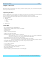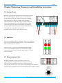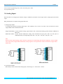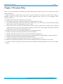
1
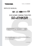
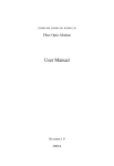
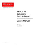
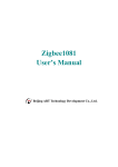
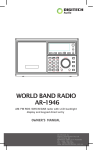
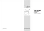
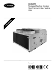
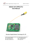
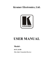
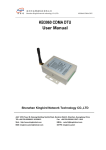
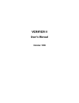
RTU6103
User’s Manual
Beijing ART Technology Development Co., Ltd.
RTU6103 User’s Manual
V6.021
Contents
Contents ................................................................................................................................................................................2
Chapter 1 Overview ..............................................................................................................................................................3
Chapter2 Subsystem Parameters and Installation Instruction..............................................................................................6
2.1 System Power..........................................................................................................................................................6
2.2 Indicator ..................................................................................................................................................................6
2.3 Programming Cable ................................................................................................................................................6
2.4 Analog Input............................................................................................................................................................7
2.5 Analog Output .........................................................................................................................................................8
2.6 Digital Input ............................................................................................................................................................8
2.7 Digital Output .........................................................................................................................................................9
2.8 CAN Bus...............................................................................................................................................................10
2.9 Ethernet Connection..............................................................................................................................................10
2.10 Serial Communication.........................................................................................................................................10
2.11 RS-485 Communication......................................................................................................................................11
2.12 Reset button ........................................................................................................................................................11
Chapter 3 Warranty Policy .................................................................................................................................................12
BUY ONLINE at art-control.com or CALL +86-(0)10-51289836(CN)
2
RTU6103 User’s Manual
V6.021
Chapter 1 Overview
RTU6103 has ability to communicate, large capacity, powerful in computing capacity, easily do secondary development,
and strong environment adaptiveness.
Unpacking Checklist
Check the shipping carton for any damage. If the shipping carton and contents are damaged, notify the local dealer or
sales for a replacement. Retain the shipping carton and packing material for inspection by the dealer.
Check for the following items in the package. If there are any missing items, contact your local dealer or sales.
¾ RTU6103 Module
¾ ART Disk
a) user’s manual (pdf)
b) drive
c) catalog
¾ Warranty Card
FEATURES
※ CPU: 32-bit RISC Processor (ARM7TDMI core)
※ Working frequency: 55MHz (external oscillation: 18.432MHz)
※ 2 Mbytes data Flash
※ 8 Kbytes EEprom
※ 256Kbytes internal high-speed Flash
※ 64Kbytes internal high-speed SRAM
※ Analog Input: 8SE/4DI, 12/14/16 bit (hardware configuration),
Single-ended range: 0~5V, 0~10V, ±5V, ±10V, differential range: ±5V, ±10V (software configuration),
and can also be configured 0~ 20mA, 4~20mA current-mode through hardware.
※ Analog Output: 12-bit 4-ch, 0~5V, 0~10V, ±5V, ±10V (isolation)
※ Digital Input/Output: 32-ch input (dry/wet contact, TTL compatible)/output (open-collector),
Every 8-ch can be defined as a group, and each group can be configured by hardware (isolation)
※ Accurate RTC Real Time Clock (0.48uA@3V(Typical value), timing accuracy adjustable)
※ 10/100M base-T Ethernet interface (RJ-45)
※ 1-ch 9-wire RS-232 serial port
※ 1-ch RS485 (isolation)
※ 1-ch CAN interface compatible CAN2.0A, CAN2.0B (isolation)
※ DC converter, efficiency up to 90% (1A@12V)
※ JTAG debugging interface
※ With power supply, programmed running light, 2 CAN working lights
BUY ONLINE at art-control.com or CALL +86-(0)10-51289836(CN)
3
RTU6103 User’s Manual
V6.021
※ Power Supply: 9V~30V DC
※ Operating Temperature: -40℃ ~ +85℃
Hardware Configuration
RTU6103 hardware configuration options
1. Serial Communication
¾ 9-wire RS-232 can be selected
2. Digital Input/Output (32-ch, each 8-ch configuration)
¾ Optical isolation, isolation voltage: 2500Vrms
¾ Digital input optional(dry contact / wet contact)
¾ Digital output optional(open-collector)
Digital input and output can be selected as follows
No input/32-ch output, 8-ch input/24-ch output, 16-ch input/16-ch output, 24-ch input/8-ch output, 32-ch input/no
output.
Note: when select RTU6103, please tell the salesperson which configuration you want, or we will provide you RTU6103
with the default configuration.
RTU6103 default configuration
¾
¾
¾
¾
¾
¾
Serial Communication: 9-wire RS-232, baud rate is 96000bps
RS-485
Ethernet IP Address: 192.168.2.80
Analog Input Range: ±10V (isolation)
Analog Output Range: ±10V (isolation)
Digital Input/Output: 16-ch input/16-ch output
BUY ONLINE at art-control.com or CALL +86-(0)10-51289836(CN)
4
RTU6103 User’s Manual
V6.021
The Terminal Diagram
BUY ONLINE at art-control.com or CALL +86-(0)10-51289836(CN)
5
RTU6103 User’s Manual
V6.021
Chapter2 Subsystem Parameters and Installation Instruction
2.1 System Power
RTU6103 equipped with high efficiency switching power supply,
Provide power supply for the entire system. Except PWRIN
power supply terminals, DI_COM provides power for digital
input of wet contact, DO_pwr provides power for digital
output (open-collector). Specific energy consumption depends
on the actual workload. DC 9-30V wide-range power supply,
with reverse protection. Power connection diagram shown as
the left, PWRIN connected with the GND, DI_COM connects
with digital wet contact power, DO_pwr and
D0_GND connect with OC (open-collector) power.
2.2 Indicator
RTU6103 is equipped with four LED lights. PWR is power indicator,
STA is process control status indicator, RUN is CAN running indicator,
ERR is CAN running error indicator.
When the power is connected to the PWRIN and GND terminals,
power on, then the PWR indicator will be on. When the program
started running, STA indicator is flashing, RUN indicator is on when
CAN is connected.
2.3 Programming Cable
RTU6103 use the IDC pin spacing of 2.0mm connects with
programming cable. If programming cable need to be connected,
inset 1-pin of the programming cable (there is number instructions
of the terminal, the cable color is red) to IDC socket (prohibit power operation),
the other end of programming cable use printer extension line to connect with PC.
BUY ONLINE at art-control.com or CALL +86-(0)10-51289836(CN)
6
RTU6103 User’s Manual
V6.021
If use a custom programming cable, refer to the JTAG pins to make
the programming cable.
2.4 Analog Input
RTU6103 has 8-ch analog input, isolation voltage is 2500Vrms, and there are two input modes: voltage input and current
input.
RP5 potentiometer can adjust analog input full-scale.
1) Voltage Input Mode
In voltage mode, RTU6103 analog input range: ±10V (default), ±5V, 0~10V, 0~5V and we can use software to select
single-ended mode or differential mode.
Single-ended Mode: connect external analog signal with the AIx, and external analog ground with the ADGND of
RTU6103.
Differential Mode: connect external differential analog with the RTU6103 input ports, there are four ports in
differential mode, corresponding to the AI0 ~ AI1, AI2 ~ AI3, AI4 ~ AI5, AI6 ~ AI7.
Note:
When connect external analog, please select the right range to avoid damage the internal components, and we should
select work mode (single-ended, differential) in the program to correspond to the external connection (single-ended,
differential).
2) Current Input Mode
RTU6103 provides current mode analog input, current range: 0 ~ 20mA and 4 ~ 20mA.
BUY ONLINE at art-control.com or CALL +86-(0)10-51289836(CN)
7
RTU6103 User’s Manual
V6.021
Note:
When select the current mode, we should weld resistance in the AD terminal.
2.5 Analog Output
RTU6103 has 4-ch analog output, output range: 0~5 V, 0~10V, ±5V, ±10V (default), isolation voltage 2500Vrms.
Potentiometer RP2, RP1, RP4, RP3 adjust the analog output zero-point of DAO0 ~ DAO3;
RP7, RP6, RP9, RP8 adjust the analog output full-scale of DAO0 ~ DAO3.
Connection method shown as the following, connect the external load to DAOx and DAGND port.
Note: The analog output is voltage signal, can not drive high current loads. If necessary, please add an external drive.
2.6 Digital Input
RTU6103 has 32-ch digital input/output, Digital input and output can be selected as follows:
No input/32-ch output, 8-ch input/24-ch output, 16-ch input/16-ch output,
24-ch input/8-ch output, 32-ch input/no output.
Digital input signal compatible TTL signal, input high level is +5V~+30V, low level is 0~+1V, and with optical isolation,
isolation voltage is 2500Vrms.
Digital Input has two types: dry contact and wet contact (anode).
BUY ONLINE at art-control.com or CALL +86-(0)10-51289836(CN)
8
RTU6103 User’s Manual
V6.021
2.7 Digital Output
RTU6103 digital output is the isolated open-collector mode. Connection methods: connect DO_pwr with external power
supply positive (give voltage according to users’ needs), connect the external power ground with the DO_GND, and
connect with the system power ground. Connect load between DO_pwr and DOxx, the current flows from the power
positive to load and then back to ground through the DO
The max voltage is connected toRTU6103 can up to 50V, the maximum continuous operating current is 500mA, each
channel’s maximum power consumption is 1W, and the total maximum power consumption of 8 channels is 2.25W
(Note: The above parameters are limits, over limit will damage the device).
Digital output connection
Internal structure of digital output
BUY ONLINE at art-control.com or CALL +86-(0)10-51289836(CN)
9
RTU6103 User’s Manual
V6.021
2.8 CAN Bus
RTU6103 provide 1-ch isolated CAN bus interface, compatible with CAN2.0B, CAN bus interface can be connected
with the host computer or with another RTU devices. Connection shown in the figure:
2.9 Ethernet Connection
2.10 Serial Communication
RTU6103 provides an asynchronous serial port, DB9 male connector, 9-wire serial port.
BUY ONLINE at art-control.com or CALL +86-(0)10-51289836(CN)
10
RTU6103 User’s Manual
V6.021
DB9 connector, 9-wire serial port
2.11 RS-485 Communication
RTU6103 provides isolated RS-485 communication interface, the identification and connection method of RS-485
mode shown in the figure:
2.12 Reset button
The reset button can make the system restore the default settings:
Serial communication: 9-wire RS-232, the baud rate is 9600bps (DB9);
Ethernet IP Address: 192.168.2.80.
BUY ONLINE at art-control.com or CALL +86-(0)10-51289836(CN)
11
RTU6103 User’s Manual
V6.021
Chapter 3 Warranty Policy
Thank you for choosing ART. To understand your rights and enjoy all the after-sales services we offer, please read the
following carefully.
1. Before using ART’s products please read the user manual and follow the instructions exactly. When sending in
damaged products for repair, please attach an RMA application form which can be downloaded from:
www.art-control.com.
2. All ART products come with a limited two-year warranty:
¾ The warranty period starts on the day the product is shipped from ART’s factory
¾ For products containing storage devices (hard drives, flash cards, etc.), please back up your data before sending
them for repair. ART is not responsible for any loss of data.
¾ Please ensure the use of properly licensed software with our systems. ART does not condone the use of pirated
software and will not service systems using such software. ART will not be held legally responsible for products
shipped with unlicensed software installed by the user.
3. Our repair service is not covered by ART's guarantee in the following situations:
¾ Damage caused by not following instructions in the User's Manual.
¾ Damage caused by carelessness on the user's part during product transportation.
¾ Damage caused by unsuitable storage environments (i.e. high temperatures, high humidity, or volatile chemicals).
¾ Damage from improper repair by unauthorized ART technicians.
¾ Products with altered and/or damaged serial numbers are not entitled to our service.
4. Customers are responsible for shipping costs to transport damaged products to our company or sales office.
5. To ensure the speed and quality of product repair, please download an RMA application form from our company
website.
BUY ONLINE at art-control.com or CALL +86-(0)10-51289836(CN)
12