1
RP-3180
MINI Thermal
Printer
USER'S MANUAL
MANUAL REVISION V8.1
TVS Electronics Limited
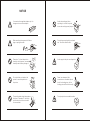
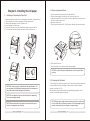
NOTICE
You must use the supplied adapter only. It is
dangerous to use other adapters.
Avoid external impact when
operating, do not fall the printer
down and avoid vigorously impact.
Make sure the printer power is off before
plug or unplug the cable.
Do not plug or unplug with your hands
wet. You can be electrocuted.
Please don t place the printer in
humidity or dusty space, excessive
humidity and dust may damage it.
Avoid magnetic objects near the printer.
Do not put foods or drinks on the
printer, in case that splash into
the printer.
Don t use tweezers, knife,
screwdriver or other hard objects
touch the heating piece; for the
heating piece will be hurt eternally.
The print head has a high temperature
after work. Please don t touch the
print head or touch the motor shell
in case scalded.
Do not put printer on unstable surface.
INTRODUCTION
The RP-3180 Thermal Printer is designed for use with electronic instruments
such as system ECR, POS, banking equipment, computer peripheral
equipment, etc.
The main features of the printer are as follows:
1. High speed printing: 180mm per second max.
2. Low noise thermal printing.
3. RS-232, Parallel, USB interface Selectable.
4. The data buffer allows the unit to receive print data even during printing.
5. Peripheral units drive circuit enables control of external devices such as
cash drawer.
6. Bar code printing is possible by using a bar code command.
7. Support auto Store Logo or Hello Logo printing.
8. Enable to change some functions by DIP Switch.
Table of Contents
Chapter 1. Setting up the Printer ............................................... 1
1-1. Unpacking ............................................................................ 1
1-2. Installing the printer ............................................................... 1
1-3. Using the Printer .................................................................... 2
Chapter 2. Connecting the cables ............................................. 3
2-1. Connecting the AC Cable ....................................................... 3
2-2. Connecting the AC adapter to the printer ................................ 3
2-3. Connecting Interface Cable and Drawer Cable to the printer ..... 4
Chapter 3. Installing the roll paper ............................................ 5
3-1. Installing or Replacing the Paper Roll ...................................... 5
3-2. Removing Jammed Paper ....................................................... 6
Please be sure to read the instruction in this manual carefully before
using your new RP-3180.
3-3. Cleaning the Print Head .......................................................... 6
Chapter 4. The self test .............................................................. 7
Chapter 5. Hexadecimal Dumping .............................................. 7
Chapter 6. DIP Switch Functions................................................. 8
Chapter 7. Interface .................................................................... 9
Chapter 8. Specification ............................................................. 11
Chapter 9. PRINT CONTROL COMMAND .................................... 12
9-1 Command List ........................................................................ 12
WARNING
Some semiconductor devices are easily damaged by static
electricity. You should turn the printer"OFF", before you connect or
remove the cables on the rear side, in order to guard the printer
against the static electricity. If the printer is damaged by the static
electricity,you should turn the printer"OFF".
NOTE: The socket-outlet shall be near the equipment and it shall be
easy accessible.
All specifications are subjected to change without notice.
9-2 Descriptions of Each Item ........................................................ 13
9-3 Control Commands ................................................................. 13
Chapter 10. Printer Driver ......................................................... 29
10-1 How to use Logo Download Tool ............................................ 30
10-2 Setting Printer Properties
..................................................... 32
Chapter 1. Setting up the Printer
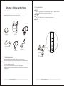
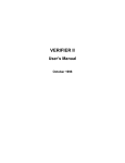
1-1. Unpacking
Your printer box should include these items. If any items are damaged or
missing, please contact your dealer for assistance.
1-3. Using the Printer
BUTTON
Press the FEED button once to advance paper one line. You can also hold
down the FEED button to feed paper continuously.
Panel lights
POWER
The POWER light(green) is on whenever the printer is on.
ON LINE
This light(green)is on when the printer is on line.
RP-3180
Roll paper
Cable
POWER
ON LINE
Or
Operator s M anual
FEED
AC Adapter
Power cord
1-2. Installing the printer
Avoid locations in direct sunlight or subject to excessive heat.
Avoid using or storing the printer in places subject to excessive moisture.
Do not use or store the printer in a dusty or dirty area. Avoid places subject
to intense vibration or shock.
Choose a stable and flat place for proper use of the printer.
Make sure that there is enough space around the printer so that it can be
used easily.
RP-3180 USER'S MANUAL
01
RP-3180 USER'S MANUAL
02
Chapter 2. Connecting the cables
2-3. Connecting Interface Cable and Drawer Cable to the printer
2-1. Connecting the AC Cable
NOTE:To remove the DC cable connector, make sure that the power
supply s power cord is unplugged; then grasp the connector at the
arrow and pull it straight out.
2-2. Connecting the AC adapter to the printer
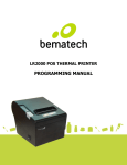
You can connect up the three cables to the printer. They all connect to the
connector panel on the back of the printer, which is shown below:
Drawer kick-out Cable
Interface Connector Cable
Connect the Host Computer (POS/ECR) to the printer using an interface cable
that matches the specifications of the printer and the Host computer
(POS/ECR). Be sure to use a drawer that matches the printer s specification.
1). Turn off both the printer and the Host computer (POS/ECR).
2). Plug the interface cable connector into the printer s interface connector,
then tighten the screws on both sides of the connector. In case of the
parallel interface, squeeze the wire dips on the printer together until they
lock in place on both sides of the connector.
3). Plug the drawer cable into the drawer kick-out connector on the back of the
printer next to the interface connector. Do not connect a telephone line to
the drawer kick-out connector; otherwise the printer and the telephone line
may be damaged.
4). Turn on the Printer and Host computer (POS/ECR).
WARNING
Power Connector Cable
NOTE:Before connecting any of the cables, make sure that both the
printer and the host are turned off.
RP-3180 USER'S MANUAL
03
When connecting or disconnecting the power supply from the
printer, make sure that the power supply is not plugged into an
electrical outlet. Otherwise you may damage the power supply or
the printer.
If the power supply`s rated voltage and your outlet`s voltage do not
match, contact your dealer for assistance. Do not plug in the power
cord. Otherwise, you may damage the power supply or the printer.
RP-3180 USER'S MANUAL
04
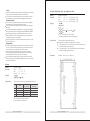
Chapter 3. Installing the roll paper
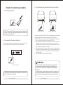
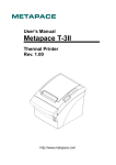
3-1. Installing or Replacing the Paper Roll
1.
2.
3.
4.
5.
6.
Make sure that the printer is not receiving data; otherwise, data may be lost.
Open the paper roll cover by pressing the cover-open button.
Remove the used paper roll core if there is one.
Insert the paper roll as shown.
Be sure to note the correct direction that the paper comes off the roll.
Pull out a small amount of paper, as shown. Then close the cover.
A
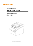
3-2. Removing Jammed Paper
1. Turn the printer off and press the cover open button.
2. Remove jammed paper, reinstall the roll, and close the cover.
3. If paper is caught in the cutter and you cannot open the printer cover, open
the cutter cover as shown in A.
4. Open the cutter cover.
5. Turn the knob (as shown in B). Until the cutter blade to the normal position.
B
B
A
6. Close the cutter cover.
7. Open the printer cover and remove the jammed paper.
NOTE:Do not touch the print head because it can be very hot after
printing.
Incorrect
Correct
C
3-3. Cleaning the Print Head
NOTE:Be sure to use paper rolls that meet the specifications. Do
not use paper rolls that have the paper glued to the core because
the printer cannot detect the paper end correctly.
Turn off the printer, open the paper roll cover, and clean the thermal elements
of the print head with a cotton swab moistened with an alcohol solvent
(ethanol, methanol, or IPA).
Recommends cleaning the thermal head periodically (generally every 3
months) to maintain receipt print quality.
NOTE:Do not open the print cover while the printer is operating.
This may damage the printer.
NOTE:When closing the cover, press the center of printer cover
firmly to prevent paper miss-loading
RP-3180 USER'S MANUAL
05
NOTE:After printing, the print head can be very hot. Be careful not to
touch it and to let it cool before you clean it. Do not damage the print
head by touching it with your fingers or any hard object.
RP-3180 USER'S MANUAL
06
Chapter 4. The self test
The self-test checks whether the printer has any problems. If the printer does
not function properly, contact your dealer.
1. Make sure paper roll has been installed properly.
2. Turn on the power while holding down the FEED button. The self-test begins.
3. The printer is ready to receive data when it completes the self-test.
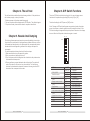
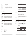
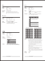
Chapter 6. DIP Switch Functions
There is a DIP Switch on the bottom of printer. It is easy to change some
functions of the printer through setting DIP pins to [On] or [Off].
The default setting for all DIP pins are [ON] Position.
Note: Changes in DIP switch settings are recognized only when the printer
power is turned on or when the printer is reset by using the interface. If the
DIP switch setting is changed after the printer power is turned on, the change
does not effect until the printer is turned on again or is reset.
Chapter 5. Hexadecimal Dumping
This feature allows experienced users to see exactly what data is coming to
the printer.This can be useful in finding software problems. When you turn on
the hexadecimal dump function, the printer prints all commands and data in
hexadecimal format along with a guide section to help you find specific
commands.
To use the hexadecimal dump function, follow these steps:
1. Make sure that there is a roll paper in the printer.
2. After you make sure that the printer is off.
3. Turn on the power while holding down the on line button,the printer enters
the hexadecimal dump mode.
4. Run any software program that sends data to the printer. The printer will
print all the codes it receives in a two-column format. The first column
contains the hexadecimal codes and the second column gives the ASCII
characters that correspond to the codes.
On
DIP
No
3
4
5
6
7
8
DIP No
DIP3
Beeper enable / disable
DIP4
Print Density
DIP5
Auto-cutter enable / disable
DIP6
Default font size select
DIP7
DIP8
07
1
2
DIP1 & DIP2
Baud Rate select
RP-3180 USER'S MANUAL
Off
ON/OFF
On & On
On & Off
Off & On
Off & Off
On
Off
On
Off
On
Off
On
Off
RP-3180 USER'S MANUAL
08
Function
96000bps
19200bps
38400bps
115200bps
Beeper enable
Beeper disable
Print Density Light
Print Density Dark
Auto-cutter enable
Auto-cutter disable
Font: 12x24
Font: 9x17
Reserved
Reserved
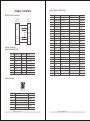
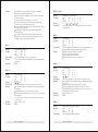
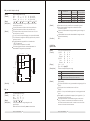
Chapter 7.Interface
RS-232C Cable Connection
PRINTER
SIDE(25P)
HOST
SIDE(9P)
(F.G) 1
1
(F.G)
(TXD) 2
(RXD) 3
3 (TXD)
2 (RXD)
7 (RTS)
8 (CTS)
(DSR) 6
(DTR) 20
6 (DSR)
4 (DTR)
(S.G) 7
5 (S.G)
Interface Connector
Serial Interface (RS-232)
Pin No.
1
2
3
4
5
6
7
20
Direction
Output
Input
Output
Input
Input
Output
Signal name
FG
TxD
RxD
RTS
CTS
DSR
SG
DTR
Function
Frame Ground
Transmit Data
Receive Data
Ready To Send
Clear To Send
Date Set Ready
Signal Ground
Data Terminal Ready
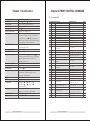
Parallel Interface (IEEE-1284)
Pin No.
1
2
3
4
5
6
7
8
9
10
11
12
13
14
15
16
17
18
19~30
31
32
33
34
35
36
Source
Host
Host/Printer
Host/Printer
Host/Printer
Host/Printer
Host/Printer
Host/Printer
Host/Printer
Host/Printer
Printer
Printer
Printer
Printer
Host
Printer
Host
Printer
Printer
Printer
Host
Compatibility Mode
nStrobe
Data0(LSB)
Data1
Data2
Data3
Data4
Data5
Data6
Data7(MSB)
nAck
Busy
Perror
Select
nAutoFd
NC
GND
FG
Logic-H
GND
nInit
nFault
GND
Dk_status
5V
nSelectIn
Drawer Connector
1
Pin No.
1
2
3
4
5
6
6
Signal name
Frame ground
Drawer Kick-out drive signal 1
Drawer open/close signal
+24V
Drawer Kick-out drive signal
Signal ground
RP-3180 USER'S MANUAL
09
Direction
Output
Input
Output
RP-3180 USER'S MANUAL
10
Nibble Mode
HostClk
PtrClk
PtrBusy/Data3,7
AckDataReq/Data2,6
Xflag/Data1,5
HostBusy
NC
GND
FG
Logic-H
GND
nInit
nDataAvail/Data0,4
ND
ND
ND
1284-Active
Byte Mode
HostClk
Data0(LSB)
Data1
Data2
Data3
Data4
Data5
Data6
Data7(MSB)
PtrClk
PtrBusy
AckDataReq
Xflag
HostBusy
NC
GND
FG
Logic-H
GND
nInit
nDataAvail
ND
ND
ND
1284-Active
Chapter 7.Specification
Printing method
Dot density
Printing width
Characters per line
Character size
Number of characters
Print speed
Paper feed speed
Line spacing (default)
Character structure
Paper roll (single-ply)
Interface (compatible)
Receive buffer
Power supply
Life
MTBF
MCBF
Temperature
Humidity
Overall dimensions
Weight (mass)
Thermal line printing
203 dpi 203 dpi ( 8 8 dots/mm)
72 mm {2.83"}, 576 dot positions
48 (default) or 72
1.25
3.00 mm
Alphanumeric characters: 95
Approx. 150 mm/s {5.9"/s} max.; 47.2 lps, max.
(3.18 mm {1/8"} feed); 35.5lps, max. (4.23 mm
{1/6"} feed, at 24 V, 28 {82 }, density level 1).
Speed is adjusted automatically depending on the
voltage applied andhead temperature.
Approx. 180 mm/s
continuous paper feed
4.23 mm {1/6"}
12 x 24 o r 9 x 17
Size: Width: 79.5 mm
0.5 mm {3.13" 0.02"}
Maximum outside diameter: 83 mm {3.26"}Paper
roll spool diameter: Inside: 12 mm {0.47"};
Outside: 18 mm {0.71"}
RS-232C/Bi-directional parallel / USB (OPTION)
28KB
+ 24 VDC 10%
Mechanism: 15,000,000 lines
Thermal head: 100 million pulses, 100 km
Autocutter: 1,500,000 cuts
360,000 hours
52,000,000 lines
Operating: 5 ~ 45 {41 ~113 }
Storage: -10 ~ 50 {14 ~122 },
except for paper
Operating: 10 to 90% RH
Storage: 10 to 90% RH, except for paper
145(W) 192(D) 142(H)mm
Approximately:2kg
RP-3180 USER'S MANUAL
11
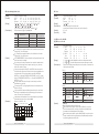
Chapter 8.PRINT CONTROL COMMAND
8-1 Command List
No.
1
2
3
4
5
6
7
8
9
10
11
12
Command
LF
CR
ESC !
ESC *
ESC 2
ESC 3
ESC 9
ESC @
ESC A
ESC D
ESC H
ESC I
13
ESC J
14
15
ESC L
ESC V
Description
Printing and paper feed
Back to printing
Select print mode
Specifying the bit image mode
Specifying 1/6-inch line feed rate
Setting line feed rate of minimum pitch
Generating the specified pulses
Initializing the printer
Set line spacing
Select character Double-height mode
Select character Double-height mode
Select character Double-height mode
Printing and feeding paper in
minimum pitch
Selecting page mode
Printing bit image
16
ESC W
Defining the print area in page mode
17
ESC X
18
ESC d
19
ESC I
20
ESC j
21
22
23
24
25
26
ESC m
ESC p
ESC M
GS !
GS *
GS /
Select character Double-width mode
Printing and feeding the paper by
n lines
Full cut
Printing and feeding paper in
minimum pitch
Partial cut
Generating the specified pulses
Select character fonts
Select character size
Defining the download bit image
Printing the downloaded bit image
27
GS V
Cutting the paper
28
GS v 0
Printing of raster bit image
29
GS h
Specifying the height of the bar code
30
GS k
Printing the bar code
31
32
FS p
FS q
Print NV bit image
Define NV bit image
RP-3180 USER'S MANUAL
12
Hexadecimal Code
<0A>
<0D>
<1B><21><n>
<1B><2A><m><n1><n2>d1...dk
<1B><32>
<1B><33><n>
<1B><39><m><n1><n2>
<1B><40>
<1B><41><n>
<1B><44>
<1B><48><n>
<1B><49>
Page
13
13
13
14
15
15
16
16
16
16
17
17
<1B><4A><n>
28
17
<1B><4C>
<1B><56><n1><n2>d1...dk
<1B><57><xL><xH><yL><yH>
<dxL><dxH> <dyL><dyH>
<1B><58><n>
17
18
29
18
19
<1B><64><n>
30
20
<1B><69>
20
<1B><6A><n>
32
20
<1B><6D>
<1B><70><m><n1><n2>
<1B><4D><n>
<1D><21><n>
<1D><2A><n1><n2>d1...dk
<1D><2F><m>
(1)<1D><56><m>
(2)<1D><56><m><n>
<1D><76><30><m><xL><xH>
<yL><yH>d1...dk
<1D><68><n>
(1)<1D><6B><m>d1...dk<NUL>
(2)<1D><6B><m><n>d1...dk
<1C><70><n>
<1C><71><n>
21
21
21
22
23
23
24
36
25
26
37
26
27
38
28
[Description]
8-2 Descriptions of Each Item
[Name]
[Format]
[Range]
[Description]
[Details]
[Default]
[Example]
Selects print mode(s) using n as follows:
The name of the command.
The code sequence.
Gives the allowable ranges for the arguments.
Describes the command's function.
Describes the usage of the command in detail.
Gives the default values, if any, for the command parameters.
Gives examples of how to use the command.
Bit
0
1
2
3
4
Hex indicates the hexadecimal equivalents.
Decimal indicates the decimal equivalents.
5
6
7
8-3 Control Commands
[Details]
[Description]
[Details]
[See Also]
Print and line feed
ASCII
LF
Hex
0A
Decimal
10
Prints the data in the print buffer and feeds one line based on the
current line spacing.
This command sets the print position to the beginning of the line.
ESC 2, ESC 3
[Description]
[Details]
[See Also]
[Default]
[See Also]
Print and carriage return
ASCII
CR
Hex
0D
Decimal
13
When automatic line feed is enabled, this command functions the
same as LF;
When automatic line feed is disabled, this command is ignored.
Sets the print starting position to the beginning of the line.
The automatic line feed is ignored with a serial interface model.
LF
[Name]
[Format]
ESC ! N
[Range]
Off
On
Off
On
-
00
10
00
20
-
0
16
0
32
-
Function
Default font
Undefined
Undefined
Undefined
Double-height mode not selected
Double-height mode selected
Double-width mode not selected
Double-width mode selected
Undefined
Undefined
Select bit-image mode
ASCII
ESC
* m
n1
n2
d1...dk
Hex
1B
2A m
n1
n2
d1...dk
Decimal
27
42 m
n1
n2
d1...dk
m = 0, 1, 3 2, 33 , 0
n1
255 , 0
n2
3, 0
d
255
Selects a bit-image mode using m for the number of dots specified
by (n1 + n2 x 256). Set a bit to 1 to print a dot, or set a bit to 0 to not
print a dot. d indicates the bit image data. The modes selectable by
m are as follows:
[Range]
[Description]
Vertical Direction
Horizontal Direction
Number Dot Density Dot Density Number of Data
of Dots
(dpi)
(dpi)
(K)
8-dot single-density
0
8
60
90
n1 + n2 x 2 56
1 8-dot double-density
8
60
180
n1 + n2 x 2 56
32 24-dot single-density
24
180
90
(n1 + n2 x 256) x 3
33 24-dot double-density
24
180
180
(n1 + n2 x 256) x 3
m
[Name]
[Format]
Decimal
(1)ESC * m n1 n2 d1...dk
CR
[Name]
[Format]
Hex
When both double-height and double-width modes are selected,
quadruple size characters are printed.
The printer can underline all characters.
When some characters in a line are double or more height, all the
characters on the line are aligned at the baseline.
GS ! can also select character size. However, the setting of the last
received command is effective.
Emphasized mode is effective for alphanumeric and Kanji. All print
modes except emphasized mode is effective only for alphanumeric.
N=0
GS !
LF
[Name]
[Format]
Off/On
Select print mode(s)
ASCII
ESC
!
Hex
1B
21
Decimal
27
33
0
n
255
RP-3180 USER'S MANUAL
n
n
n
Mode
[dpi: dots per 25.4 mm {1"}]
13
RP-3180 USER'S MANUAL
14
[Details]
If the values of m is out of the specified range, n1 and data
following are processed as normal data.
The n1 and n2 indicate the number of dots of the bit image in the
horizontal direction.
The number of dots is calculated by n1 + n2 x 256.
If the bit-image data input exceeds the number of dots to be
printed on a line, the excess data is ignored.
d indicates the bit-image data. Set a corresponding bit to 1 to print
a dot or to 0 to not print a dot.
After printing a bit image, the printer returns to normal data
processing mode.
This command is not affected by print modes (emphasized,
double-strike, underline,character size or white/black reverse
printing), except upside-down printing mode.
ESC 9 m n 1 n2
[Name]
[Format]
[Range]
[Description]
ESC @
[Name]
[Format]
ESC 2
[Description]
[Name]
[Format]
[Description]
[Details]
[See Also]
Select default line spacing
ASCII
ESC
2
Hex
1B
32
Decimal
27
50
Selects approximately 4.23 mm {1/6"}spacing.
The line spacing can be set independently in standard mode and in
page mode.
ESC 3
[Name]
[Format]
[Range]
[Description]
[Details]
[Default]
[See Also]
[Details]
Set line spacing
ASCII
ESC
3
n
Hex
1B
33
n
Decimal
27
51
n
0
n
255
Sets the line spacing to [n x vertical or horizontal motion unit].
The line spacing can be set independently in standard mode and in
page mode.
In standard mode, the vertical motion unit (y) is used.
The maximum paper feed amount is 1016 mm {40"}. Even if a paper
feed amount of
more than 1016 mm {40"}is set, the printer feeds the paper only
1016 mm {40"}.
Approx 4.23mm {1/6"}.
ESC 2
[Range]
[Description]
[Details]
[Default]
[See Also]
[Description]
15
Set line spacing
ASCII
ESC
A
n
Hex
1B
41 n
Decimal
27
65 n
0
n
255
Sets the line spacing to [n x vertical or horizontal motion unit].
The line spacing can be set independently in standard mode and in
page mode.
In standard mode, the vertical motion unit (y) is used.
The maximum paper feed amount is 1016 mm {40"}. Even if a
paper feed amount of more than 1016 mm {40"}is set, the printer
feeds the paper only 1016 mm {40"}.
Approx 4.23mm {1/6"}.
ESC 2
ESC D
[Name]
[Format]
RP-3180 USER'S MANUAL
Initialize printer
ASCII
ESC
@
Hex
1B
40
Decimal
27
64
Clears the data in the print buffer and resets the printer mode to the
mode that was in effect when the power was turned on.
The data in the receive buffer is not cleared.
The macro definition is not cleared.
The NV bit image data is not cleared.
The data of the NV user memory is not cleared.
ESC A n
[Name]
[Format]
ESC 3 n
Generating the specified pulses
ASCII
ESC
9
m
n1
n2
Hex
1B
39
m
n1
n2
Decimal
27
57
m
n1
n2
m = 0, 0
n1
255 , 0
n2
255
The signals specified by n1 and n2 are output to the connector
pin specified by m .
Select character Double-height mode
ASCII
ESC
D
Hex
1B
44
Decimal
27
68
Select character Double-height mode.
RP-3180 USER'S MANUAL 16
ESC H n
[Name]
[Format]
[Range]
[Description]
ESC V n1 n2 d1...dk
Select character Double-height mode
ASCII
ESC
H
n
Hex
1B
48
n
Decimal
27
72
n
1
n
8
Select character Double-height mode.
[Name]
[Format]
[Range]
[Description]
ESC I
[Name]
[Format]
[Description]
Select character Double-height mode
ASCII
ESC
I
Hex
1B
49
Decimal
27
73
Select character Double-height mode.
[Details]
ESC J n
[Name]
[Format]
[Range]
[Description]
[Details]
Print and feed paper
ASCII ESC J n
Hex 1B 4A n
Decimal 27 74 n
0 = n = 255
Prints the data in the print buffer and feed the paper [n x vertical or
horizontal motionunit].
After printing is completed, this command sets the print starting
position to the beginning of the line.
The paper feed amount set by this command does not affect the
values set by ESC 2 or ESC 3.
In standard mode, the printer uses the vertical motion unit (y).
The maximum line spacing is 1016mm {40"}. When the setting
value exceeds the maximum, it is converted to the maximum
automatically.
ESC W xL xH yL yH dxL dxH dyL dyH
[Name]
[Format]
[Range]
[Description]
ESC L
[Name]
[Format]
[Description]
[Details]
Select page mode
ASCII
ESC
L
Hex
1B
4C
Decimal
27
76
Switches from standard mode to page mode.
This command is enabled only when processed at the beginning of
a line in standard mode.
This command has no effect in page mode.
The following command is not available in page mode, Print raster
bit image: GS v 0
The printer returns to standard mode when power is turned on, the
printer is reset, or ESC @ is used.
RP-3180 USER'S MANUAL
17
Printing bit image
ASCII
ESC
V
n1
n2
d1...dk
Hex
1B
56 n1
n2
d1...dk
Decimal
27
86 n1
n2
d1...dk
0
n1,n2
65535
n1, n2: number of dot lines in the vertical direction.
n1 represents the least significant byte and n2 represents the most
significant byte.
Number of dot lines=n2 x 256+n1 Ignored when n1=n2=0.
Enter the image data following n1 and n2. The amount of image
data is as follows:Amount of image data=(n2 x 256+n1) x 72 bytes
The data following n1 and n2 is printed out entirely as image data.
Enter the data from the leftmost of the top dot line to the bottom
dot line.
If you specify bit image without entering CR or LF after inputting
characters for a rangenot exceeding one line, the characters of
that line and the bit image are overlapped when printed out. At this
time, all modifications to characters are valid. Note that the
characters are not normally printed out when overlapped unless a
value more than the character height is specified by n2 x n1. You
can not overlap bit images with stamps or ruler lines. If you specify
bit images, the stamp or the ruler line is suspended. After the bit
image is complete, the print-out of stamps or ruler line restarts.
[Details]
Defining the print area in page mode
ASC II
ESC
W
xL xH yL yH dxL dxH dyL dyH
Hex
1B
57 xL xH yL yH dxL dxH dyL dyH
Decimal
27
87
xL xH yL yH dxL dxH dyL dyH
0 = xL, xH, yL, yH, dxL, dxH, dyL, dyH = 255
except for dxL = dxH = 0 or dyL = dyH = 0
Defines the location and size of the print area.
Horizontal start point = [(xL + xH x 256) x basic calculation pitch]
inches
Vertical start point = [(yL + yH x 256) x basic calculation pitch]
inches
Horizontal length = [(dxL + dxH x 256) x basic calculation pitch]
inches
Vertical length = [(dyL + dyH x 56) x basic calculation pitch]
inches
When standard mode is selected, this command only executes the
internal flagging of the printer without affecting the printing in
standard mode.
If the horizontal start point or vertical start point is out of the
printable area, this command is canceled and the next data is
handled as normal data.
RP-3180 USER'S MANUAL
18
If the horizontal length or vertical length is 0, this command is
canceled and the next data is handled as normal data.
If the horizontal start point + horizontal length is greater than
the horizontal printable area, the horizontal printable area horizontal start point is taken as the horizontal length.
If the vertical start point + vertical length is greater than the
vertical printable area, the ertical printable area vertical start
point is taken as the vertical length.
Fractions resulting from calculations are corrected with the
minimum pitch of the mechanism, and the remainder are omitted.
The horizontal start point and horizontal length are calculated with
the basic calculation pitch (x). The vertical start point and vertical
length are calculated with the basic calculation pitch (y).
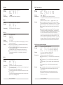
When the horizontal starting position , vertical starting position,
printing area width, and printing area height are defined as X, Y,
Dx,and Dy respectively, the printing area is set as shown in the
figure below.
(X,Y)
[Name]
[Format]
[Range]
[Description]
[Details]
[See Also]
Print and feed n lines
ASCII
ESC
d
n
Hex
1B
64
n
Decimal
27
100
n
0
n
255
Prints the data in the print buffer and feeds n lines.
This command sets the print starting position to the beginning of
the line.
This command does not affect the line spacing set by ESC 2
or ESC 3.
The maximum paper feed amount is 1016 mm {40"}. If the paper
feed amount (n x line spacing) of more than 1016 mm {40"} is
specified, the printer feeds the paper only 1016 mm {40"}.
ESC 2, ESC 3
ESC I
Dx
Dy
ESC d n
[Name]
[Format]
Print area
Paper Feed Direction
[Description]
[Details]
Full cut
ASCII
ESC
i
Hex
1B
69
Decimal
27
105
Cut the paper fully.
During cutting, printing and paper feeding is stopped.
This command is valid only when an auto-cutter is connected.
(X+Dx-1,Y+Dy-1)
[Default]
This printable area for this printer is approximately 72.2 mm
{512/180"}in the horizontal direction and approximately 117.3 mm
{1662/360"} in the vertical direction.
XL = xH = y L = yH = 0
dxL = 0, dxH = 2, dyL = 126, dyH = 6
ESC j n
[Name]
[Format]
[Range]
[Description]
ESC X n
[Name]
[Format]
[Range]
[Description]
Select character Double-width mode
ASCII
ESC
X
n
Hex
1B
58 n
Decimal
27
88 n
1
n
8
Select character Double-width mode.
RP-3180 USER'S MANUAL
19
[Details]
Print and feed paper
ASCII
ESC
j
n
Hex
1B
6A
n
Decimal
27
106
n
0
n
255
Prints the data in the print buffer and feed the paper [n x vertical or
horizontal motionunit].
After printing is completed, this command sets the print starting
position to the beginning of the line.
The paper feed amount set by this command does not affect the
values set by ESC 2 or ESC 3.
In standard mode, the printer uses the vertical motion unit (y).
The maximum line spacing is 1016mm {40"}. When the setting
value exceeds the maximum, it is converted to the maximum
automatically.
RP-3180 USER'S MANUAL 20
ESC m
[Name]
[Format]
[Description]
[Details]
GS ! N
Partial cut
ASCII
ESC
m
Hex
1B
6D
Decimal
27
109
Cut the paper partially.
During cutting, printing and paper feeding is stopped.
This command is valid only when an auto-cutter is connected.
[Name]
[Format]
[Range]
[Description]
Select character size
ASCII
GS
!
n
Hex
1D
21 n
Decimal
29
33 n
0
n
255
(1
vertical number of times
8, 1 horizontal number of
times
8)
Selects the character height using bits 0 to 2 and selects the
character width using bits 4 to 7, as follows:
ESC p m n 1 n2
[Name]
[Format]
[Range]
[Description]
ESC M n
[Name]
[Format]
[Range]
[Description]
Select character fonts
ASCII
ESC M
n
Hex
1B
4D
n
Decimal
27
77
n
n =0,1,48,49
Selects character fonts.
N
0,48
1,49
[Details]
Bit
0
1
2
3
4
5
6
7
Generating the specified pulses
ASCII
ESC
p
m
n1
n2
Hex
1B
70 m
n1
n2
Decimal
27
112 m
n1
n2
m = 0, 0
n1
255 , 0
n2
255
The signals specified by n1 and n2 are output
to the connector pin specified by m .
Function
Character font A (12 x 24) selected.
Character font B (9 x 17) selected.
Decimal Number
Character height selection. See Table 2
Character width selection. See Table 1
Table 2 Character Height Selection
Hex
00
10
20
30
40
50
60
70
Hex
00
01
02
03
04
05
06
07
[Details]
[Default]
[See Also]
21
Hex Number
Table 1 Character Width Selection
The ESC ! command can also select the character fonts.
However, the setting of the last received command is effective.
RP-3180 USER'S MANUAL
Function
Decimal
0
16
32
48
64
80
96
112
Width
1 x (Standard)
2 x (Double width)
3x
4x
5x
6x
7x
8x
Decimal
0
1
2
3
4
5
6
7
Width
1 x (Standard)
2 x (Double height)
3x
4x
5x
6x
7x
8x
If n is outside of the defined range, this command is ignored.
In standard mode, the vertical direction is the paper feed direction,
and the horizontal direction is perpendicular to the paper feed
direction. However, when character orientation changes in 90.
clockwise-rotation mode, the relationship between vertical and
horizontal directions are reversed.
In page mode, vertical and horizontal directions are based on the
character orientation.
When characters are enlarged with different sizes on one line, all
the characters on the line is aligned at the baseline.
The ESC ! command can also turn double-width and double-height
modes on or off.However, the setting of the last received command
is effective.
n=0
ESC !
RP-3180 USER'S MANUAL 22
GS
n1 n2 d1...d(n1 x n2 x 8)
[Name]
[Format]
[Range]
[Description]
[Details]
m
Define downloaded bit image
ASCII
GS
*
n1
n2
d1...d(n1 x n2 x 8)
Hex
1D
2A n1
n2
d1...d(n1 x n2 x 8)
Decimal
29
42 n1
n2
d1...d(n1 x n2 x 8)
1
n1
255, 1 n2 48, n1 x n2
1536 , 0 d
255
Defines a downloaded bit image using the number of dots
specified by n1 and n2
n1 specifies the number of dots in the horizontal direction.
n2 specifies the number of dots in the vertical direction.
The number of dots in the horizontal direction is n1 x 8, in the
vertical direction it is n2 x 8.
If n1 x n2 is out of the specified range, this command is disabled.
The d indicates bit-image data. Data (d) specifies a bit printed to 1
and not printed to 0.
The downloaded bit image definition is cleared when:
1. ESC @ is executed.
2. Printer is reset or the power is turned off.
The following figure shows the relationship between the
downloaded bit image and the printed data.
0,48
1,49
2,50
3,51
[Details]
[See Also]
d1
dn2 + 2
dn2 + 2 + 1
dn2 + 2
dn2 + 2 + 1
MSB
d2
[Range]
n2 x 8 dost
When data exist in the print buffer, this command is ignored.
When a downloaded bit image has not been defined, this
command is ignored.
A portion of a downloaded bit image exceeding one line length is
not printed.
A downloaded character and a downloaded bit image cannot be
defined simultaneously.
GS *
(1) G S V m
(2) G S V m n
[Name]
[Format]
n1 x 8 dost
[Description]
Select cut mode and cut paper
(1) ASCII
GS
V
m
Hex
1D
56 m
Decimal
29
86 m
(2) ASCII
GS
V
m
n
Hex
1D
56 m
n
Decimal
29
86 m
n
(1) m = 1 , 4 9
(2) m = 6 6, 0
n
255
Performs the specified paper cutting.
m
1, 49
LSB
dn2
66
d 2 x n2 x 8
dn2 x 2
[Details]
[See Also]
GS /
GS / m
[Name]
[Format]
[Range]
[Description]
Print downloaded bit image
ASCII
GS
/
m
Hex
1D
2F
m
Decimal 29
47
m
0
m
3, 48
m
51
Prints a downloaded bit image using the mode
specified by m.
Modes that can be selected by m are shown below.
RP-3180 USER'S MANUAL
23
Dot Density in
Dot Density in
Vertical Direction Horizontal Direction
NORMAL MODE
203 DPI
203 DPI
DOUBLE WIDTH MODE
203 DPI
101 DPI
DOUBLE HEIGHT MODE
101 DPI
203 DPI
QUADRUPLE SIZE MODE
101 DPI
101 DPI
Mode Name
Print mode
Partial cut (one point left uncut)
Feeds paper (cutting position + [n x (vertical motion unit)]),
and cuts the paper partially (one point left uncut).
For (1) and (1) :
This command is effective only processed at the beginning of a line.
For (1) :
Only the partial cut is available; there is no full cut.
For (2) :
When n = 0, the printer feeds the paper to the cutting position and
cuts it.
When n 0, the printer feeds the paper to (cutting position + [n x
vertical motion unit]) and cuts it.
The paper feed amount is calculated using the vertical motion
unit (y). However, the value cannot be less than the minimum
horizontal movement amount, and it must be in even units of the
minimum horizontal movement amount.
RP-3180 USER'S MANUAL
24
GS v 0 m xL xH yL yH d1...dk
[Name]
[Format]
[Range]
[Description]
Printing of raster bit image
ASC II
GS
v
0
m xL xH yL
Hex
1D
76 30
m xL xH yL
Decimal
29 118 48
m xL xH yL
0
m
3, 48 m
51, 0 xL
255, 0
0
yL
255, 0 yH
8, 0 d
255,
k=(xL+xH x 256) x (yL+yH x 256), however,
Prints raster bit images in mode m .
m
[Example]
yH d1...dk
yH d1...dk
yH d1...dk
xH
255,
k
Dot Density in
Dot Density in
Vertical Direction Horizontal Direction
NORMAL MODE
203 DPI
203 DPI
DOUBLE WIDTH MODE
203 DPI
101 DPI
DOUBLE HEIGHT MODE
101 DPI
203 DPI
QUADRUPLE SIZE MODE
101 DPI
101 DPI
[Details]
[See Also]
Define downloaded bit image
ASCII
GS
h
n
Hex
1D
68
n
Decimal
29
104
n
1
n
255
Selects the height of the bar code.
n specifies the number of dots in the vertical direction.
N = 162
GS k
1
2
3
62
63
64
65
66
67
126
127
128 YL + yH x 256 dot
K-2
K-1
6 5
4 3
2
1
0
(1) GS k m d1...dk NUL
(2) GS k m n d1...dn
[Name]
[Format]
[Range]
[Description]
K
Print the bar code
(1) ASCII
GS
V
m
d1...dk
Nul
Hex
1D
6B m
d1...dk
00
Decimal
29
107 m
d1...dk
0
(2) ASCII
GS
k
m
n
d1...dn
Hex
1D
6B m
n
d1...dn
Decimal
29
107 m
n
d1...dn
(1) 0 m
6 (k and d depends on the bar code system used)
(2) 65 m
73 (n and d depends on the bar code system used)
Selects a bar code system and prints the bar code. m selects a bar
code system as follows:
For (1) :
m
2
3
Bar Code System
JAN13 (EAN13)
JAN 8 (EAN8)
4
CODE39
Number of Characters Remarks
48
d
57
12
k
13
48
d
57
7
k
8
48
d
57, 65 d
90,
1
k
32, 36, 37, 43, 45, 46, 47
For (2) :
[Details]
(XL + xH x 256)x 8 dot=512 dot
7
[Range]
[Description]
0
xL, xH specify the number of data in horizontal direction of the bit
image to (xL+xH x 256) bytes.
yL, yH specify the number of data in vertical direction of the bit
image to (yL+yH x 256) bytes.
In STANDARD MODE, this command is valid only when there is no
print data in the print buffer.
Any of the print modes (Character size, emphasis, double strike,
inverting, underlining, back-to-white reversing, etc.) does not
affect the raster bit image.
If the print area specified by GS L and GS W is narrower than a
minimum width, the print area for that line only is extended to the
minimum width. The minimum width is one dot in NORMAL
MODE (m=0, 48) and DOUBLE HEIGHT MODE (m=2,50), and 2
dots in DOUBLE WIDTH MODE (m=1, 49) and QUADRUPLE SIZE
MODE (m=3, 51).
Any part of data that is out of the print area is only read and
discarded in units of dot.
The setting of ESC a (Aligning characters) are also valid for the
raster bit image.
If this command is executed during macro definition, the macro
definition is suspended, and the processing of the command
starts. The macro is left undefined.
d denotes defined data. Dots to be printed are specified as
1 and those not to be printed as 0 .
When xL+xH x 256= 64:
MSB
[Name]
[Format]
Mode Name
0,48
1,49
2,50
3,51
[Details]
GS h n
m
67
68
Bar Code System
JAN13 (EAN13)
JAN 8 (EAN8)
69
CODE39
73
CODE128
Number of Characters Remarks
48
d
57
12
k
13
48
d
57
7
k
8
48
d
57, 65 d
90,
1
k 255
32, 36, 37, 43, 45, 46, 47
0
d
127
2
k 255
For (1):
This command ends with a NUL code.
When the bar code system used is JAN13 (EAN13), the printer
prints the bar code after receiving 13 bytes bar code data and
processes the following data as normal data.
When the bar code system used is JAN8 (EAN8), the printer prints
the bar code after receiving 8 bytes bar code data and processes
the following data as normal data.
LSB
RP-3180 USER'S MANUAL
25
RP-3180 USER'S MANUAL 26
For (2):
n indicates the number of bar code data, and the printer processes
n bytes from the next character data as bar code data.
If n is outside of the specified range, the printer stops command
processing and processes the following data as normal data.
In standard mode:
If d is outside of the specified range, the printer only feeds paper
and processes the following data as normal data.
If the horizontal size exceeds printing area, the printer only feeds
the paper.
This command feeds as much paper as is required to print the bar
code, regardless of the line spacing specified by ESC 2 or ESC 3.
This command is enabled only when no data exists in the print
buffer. When data exists in the print buffer, the printer processes
the data following m as normal data.
After printing bar code, this command sets the print position to the
beginning of the line.
In page mode :
This command develops bar code data in the print buffer, but does
not print it. After processing bar code data, this command moves
the print position to the right side dot of the bar code.
If d is out of the specified range, the printer stops command
processing and processes the following data as normal data. In
this case the data buffer position does not change.
If bar code width exceeds the printing area, the printer does not
print the bar code but moves the data buffer position to the left side
out of the printing area.
FS q n [xL xH yL yH d1...dk]1...[xL xH yL yH d1...dk]n
[Name]
[Format]
[Range]
Define NV bit image
ASC II
FS q n [xL xH yL yD d1...dk]1
Hex
1C 71 n [xL xH yL yD d1...dk]1
Decimal
28 113 n [xL xH yL yD d1...dk]1
1
n
4
0
xL
72
xH=0
0 yL 255
0 yL 1(when 1 (yL+yH x 256) 288)
0
d
255
k=(xL + xH x 256) x (yL+yH x 256) x8
Total defined data area = 2M bits (256K bytes)
[Description]
Define the NV bit image specified by n..
N specifies the number of the defined NV bit image .
XL, xH specifies (xL+xH x 256) x8 dots in the horizontal direction
for the NV bit image you are defining.
YL, yH specifices (yL+yH x 256) x 8 dots in the vertical direction
for the NV bit image you are defining.
[Example]
When xL = 64, xH = 0, yL = 96, yH = 0
FS p n m
[Name]
[Format]
[Range]
[Description]
Print NV bit image
ASC I I
FS p n m
Hex
1C 70 n m
Decimal
28 112 n m
1
n
4
0
m
3, 48 m 51 ,
Prints a NV bit image n using the mode specified by m.
m
0,48
1,49
2,50
3,51
Vertical
Dot Density
203 DPI
203 DPI
101 DPI
101 DPI
Mode
Normal
Double-width
Double-heigh
Quadruple
Horizontal
Dot Density
203 DPI
101 DPI
203 DPI
101 DPI
N is the number of the NV bit image .
M specifies the bit image mode.
RP-3180 USER'S MANUAL
27
RP-3180 USER'S MANUAL
28
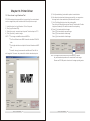
Chapter 10. Printer Driver
10-1.How to use Logo Download Tool
RP-3180 receipt printer supports Store Logo printing. You can download
max four images into printer and select which one to print on receipt.
1)
2)
3)
4)
Install the driver for Logo Download Tool on Computer.
Run [Logo Download Tool].
Select the correct connected port of printer. The default port is LTP1.
Click [Open file] to select a image.
NOTE: * The image must be Monochrome BMP file.
5) Click [download bmp], and wait the printer to save the data.
6) After the printer download the image successfully, you can preview
the image on the frame and the bmp file information as well.
7) Click [Print Bmp] button to check the printing effect.
There are four Printing Mode options: Normal, Double-width, Doubleheight and Quadruple. The default mode is Normal printing.
8) Select [1] to download the first image.
Select [2] to download the second image.
Select [3] to download the third image.
Select [4] to download the fourth image.
* The Size of Monochrome BMP file must be less than 576x2304
dots.
* The height should be in multiple of 8 dots in Monochrome BMP
file.
* Herewith, strongly recommend to use Microsoft Paint Tool to
edit image file. Otherwise, the printer will be failed to download or print.
Note: The images will be saved into the flash memory of printer.
Any new download operation will overwrite the former image.
Please use RP-3180 printer driver to set the image printing mode.
RP-3180 USER'S MANUAL
29
RP-3180 USER'S MANUAL
30
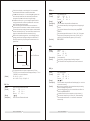
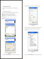
2) After install the software successfully, open [Printing Preferences...].
10-2.Setting Printer Properties
The printer driver software can be found from CD disk packaged with
printer.
1) Install the printer driver software.
The printer driver should be installed according to following steps:
Go to [Printers and Faxes] folder, click [Add a printer];
Click [next] according to the direction of installation;
Click [have disk...] , to find & open *.inf file of printer driver.
See Pic 10.2-1
And then start to install the printer software. See Pic 10.2-2
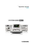
Pic 10.2-3
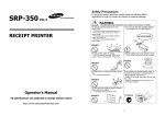
3) Open [Printing Preferences...]and [Advance] to go to Advanced Options.
Now, you can reset the Document Options by select the right items.
See Pic 10.2-4.
Pic 10.2-1
Pic 10.2-4
Pic 10.2-2
RP-3180 USER'S MANUAL
31
RP-3180 USER'S MANUAL
32