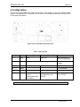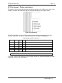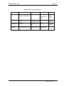
1
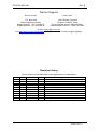
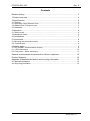
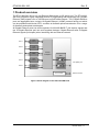
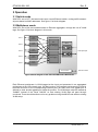
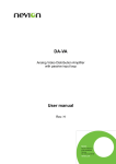
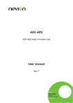
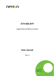
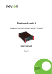
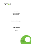
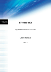
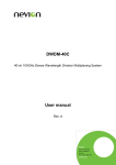
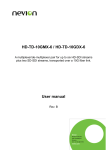
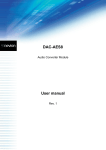
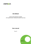
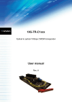
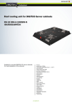
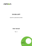
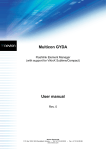
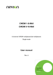
ETH-1000-SW-10G 1-Gigabit Ethernet switch with 10-Gigabit optical uplink port User manual Rev. E Nevion Nordre Kullerød 1 3241 Sandefjord Norway Tel: +47 33 48 99 99 nevion.com ETH1000-SW-10G Rev. E Nevion Support Nevion Europe Nevion USA P.O. Box 1020 3204 Sandefjord, Norway Support phone 1: +47 33 48 99 97 Support phone 2: +47 90 60 99 99 1600 Emerson Avenue Oxnard, CA 93033, USA Toll free North America: (866) 515-0811 Outside North America: +1 (805) 247-8560 E-mail: [email protected] See http://www.nevion.com/support/ for service hours for customer support globally. Revision history Current revision of this document is the uppermost in the table below. Rev. Repl. Date Sign E D C B A D C B A - 2014-11-03 2014-06-06 2013-02-20 2012-11-12 2012-03-09 AD AD AD OEH AJM Change description Chapter 6.1 and 6.1.1 updated. Updated 2 Specifications. Heat warning Updated 2.2 Network/Fiber transport layer Updated to match the current firmware First version nevion.com | 2 ETH1000-SW-10G Rev. E Contents Revision history ........................................................................................................ 2 1 Product overview ................................................................................................... 4 2 Specifications ........................................................................................................ 5 2.1 General ......................................................................................................................... 5 2.1 Application Layer Ethernet Ports ................................................................................... 5 2.2 Network/Fiber Transport Layer ...................................................................................... 5 2.3 Standards...................................................................................................................... 5 3 Operation............................................................................................................... 6 3.1 Switch mode ................................................................................................................. 6 3.2 Multiplexer mode ........................................................................................................... 6 4 Configuration ......................................................................................................... 7 5 Connections .......................................................................................................... 8 5.1 Mounting the connector module .................................................................................... 8 5.2 Terminal ports ............................................................................................................... 8 6 Module status ........................................................................................................ 9 6.1 GPI ALARM – Module Status Outputs........................................................................... 9 6.1.1 GPI connections ........................................................................................................10 6.2 Front panel – Status monitoring ...................................................................................11 General environmental requirements for Nevion equipment .................................. 13 Product Warranty.................................................................................................... 14 Appendix A Materials declaration and recycling information .................................. 15 A.1 Materials declaration ....................................................................................................15 A.2 Recycling information...................................................................................................15 nevion.com | 3 ETH1000-SW-10G Rev. E 1 Product overview The ETH-1000-SW-10G is a 5 port Ethernet Switch with a 10G uplink port. The ETH-1000SW-10G provides a highly integrated solution for aggregating and transporting up 5 Gigabit Ethernet (GbE) signals over an 10G Ethernet or fiber based network. The 5 Gigabit Ethernet ports are aggregated onto a single 10-Gigabit Ethernet (10GbE) network facing port which can be populated with Nevion SFP+ modules to facilitate optical transmission over a range of distances and optical wavelengths. All Gigabit Ethernet ports can auto-negotiate 10/100/1000 BASE-T (full duplex) signals and the 10-Gigabit Ethernet port can auto-negotiate between Gigabit Ethernet and 10-Gigabit Ethernet signals (full duplex) when interfacing with an Ethernet network. Port 1 10/100/ 1000Base-T Port 2 10/100/ 1000Base-T Port 3 10/100/ 1000Base-T Port 4 Switch/ multiplexer SFP+ 10/100/ 1000Base-T 10G uplink port Port 5 10/100/ 1000Base-T Microcontroller Remote control Figure 1 Block diagram of the ETH-1000-SW-10G nevion.com | 4 ETH1000-SW-10G Rev. E 2 Specifications Due to the amount of heat generated from these units, they need to be mounted in a frame with adequate airflow to avoid damage to the unit. On 11107 FR-2RU-10-2 external airflow support like 11131/11132 FR-FAN-1RU are recommended. 2.1 General Power +5V DC / 11W Control Control system for access to setup and module status with BITE (Built-In Test Equipment) GPI 1 in, 3 out Temperature range 0 to +40 °C Size 2 slot in a Flashlink chassis 2.1 Application Layer Ethernet Ports Number of ports 5 Connector RJ45 Format IEE 802.3, 10BASE-T, 100BASE-T, 1000BASE-T Speed Auto sensing, 10/100/1000Mbps Cables Auto sensing, MDI/MDI-X 2.2 Network/Fiber Transport Layer Number of ports 1 Connector Dual SC/UPC Wavelength 850nm, 1310nm or CWDM Optical power See relevant SFP+ datasheet Laser type See relevant SFP+ datasheet Extinction ratio See relevant SFP+ datasheet Transmission circuit fiber Single mode or Multimode 2.3 Standards Gigabit Ethernet IEE 802.3, 10BASE-T, 100BASE-T, 1000BASE-T 10 Gigabit Ethernet IEE 802.3, 10GBASE-SR, 10GBASE-LR, 10GBASEER «Jumbo» Frames Up to 10kB packet length supported. VLAN tags IEEE_802.1ad VLAN tags pass through unmodified in both the switch and the MUX mode. nevion.com | 5 ETH1000-SW-10G Rev. E 3 Operation 3.1 Switch mode With DIP1 set to OFF, the board works as a normal Ethernet switch, routing traffic between all ports based on MAC addresses. See figure 1 for block diagram. 3.2 Multiplexer mode With DIP1 set to ON, the board becomes an Ethernet aggregator, through the use of VLAN tags. See figure 2 for block diagram in this mode. Port 1 10/100/ 1000Base-T Ethernet switch Port 2 10/100/ 1000Base-T Demultiplexer/Vlan de-tagging Port 3 10/100/ 1000Base-T Port 4 10/100/ 1000Base-T Port 5 10/100/ 1000Base-T SFP+ 10G uplink port Multiplexer/Vlan tagging Remote control Microcontroller Figure 2 Block diagram of the ETH-1000-SW-10G in MUX mode Each Ethernet port/stream is VLAN tagged at the input and presented in an aggregated port/stream at the 10G network port. On the incoming 10G network port/stream the VLAN is removed and sent to the corresponding Ethernet port. No traffic from one gigabit port is allowed to enter another gigabit port inside the product. The VLAN tags used are marked as “0x8800” instead of the usual “0x8100” so that existing VLAN tags will pass through unnoticed. There should therefore not be any problem mixing the MUX mode with an existing VLAN setup. nevion.com | 6 ETH1000-SW-10G Rev. E 4 Configuration The correct configuration can either be set with a DIP switch or with the GYDA Control System. The layout of ETH-1000-SW-10G is shown in the drawing below with the DIP switch to the upper left position. Figure 3 ETH-1000-SW-10G board layout Table 1: DIP switches Switch # Label Function, DIP = ON Function, DIP = OFF Comment 1 M/S MUX SWITCH Ethernet switch or Ethernet aggregator 2-4 LED See table in chapter 6.2 5 DIP5 To be defined 6 DIP6 To be defined 7 DIP7 To be defined 8 OVR Override GYDA control. Configuration with DIP switch GYDA control. Configuration with GYDA Used to control LED usage Select configuration from GYDA All DIP switches are off when pointing towards the release handle. nevion.com | 7 ETH1000-SW-10G Rev. E 5 Connections Figure 4 Connector module for ETH-1000-SW-10G 5.1 Mounting the connector module The details of how the connector module is mounted, is found in the user manual for the subrack frame FR-2RU-10-2. This manual is also available from our web site: http://www.nevion.com/. 5.2 Terminal ports Table 2: Terminal ports Terminal Function Supported Format Mode OPT1 Optical input 10GBase-XR Input OPT2 Bi-directional 10GBase-XR Output ETH1 to 5 Electrical Ethernet 10/100/1000Base-T(x) Bi-directional GPIO Open Collector Alarms Wired alarms OC Output Laser off input Configuration TTL input Unused inputs should be terminated to avoid alarms triggered by noise. nevion.com | 8 ETH1000-SW-10G Rev. E 6 Module status The status of the module can be monitored in three ways. 1. GYDA System Controller (optional). 2. GPI at the rear of the sub-rack. 3. LED’s at the front of the sub-rack. Of these three, the GPI and the LED’s are mounted on the module itself, whereas the GYDA System Controller is a separate module giving detailed information on the card status. 6.1 GPI ALARM – Module Status Outputs These outputs can be used for wiring up alarms for third party control systems. The GPI outputs are open collector outputs, sinking to ground when an alarm is triggered. The GPI connector is shown in figures below. Electrical Maximums for GPI outputs Max current: 100mA Max voltage: 30V Be careful when connecting cables to the backplane of ETH1000-SW-10G, as the GPI connecter has 5V output. Do not connect the GPI to an Ethernet port on another unit, as this will damage the unit. nevion.com | 9 ETH1000-SW-10G Rev. E 6.1.1 GPI connections ETH-1000-SW-10G module GPI pinning: Table 3: GPI pinning Pin # Signal Name Mode Pin 1 Laser off Turn off laser. TTL input Pin 4 Status General error status for the module. Open Collector Closed under normal operation. Open if: Power is not present on module. Firmware is invalid. Pin 5 10G link Loss of 10G link. Open Collector Pin 6 Laser fail Laser fail Open Collector Pin 7 +5V +5V pin +5V Pin 8 Ground 0V / gnd pin. 0V. Figure 5 GPI connector nevion.com | 10 ETH1000-SW-10G Rev. E 6.2 Front panel – Status monitoring The status of the module can be easily monitored visually by the LED’s at the front of the module. The LEDs are visible through the front panel as shown in the figure below. Figure 6: Led positions The ETH-1000-SW-10G has 4 LED’s each showing a status corresponding to the GPI pinning. Three DIPs are used to control what function the LEDs are displaying: Table 4: Dip switches led control MODE # DIP2 DIP3 DIP4 Comment 0 ON ON ON 1: Status, 2: PIN, 3: LSR, 4: GbE ports link 1 ON ON OFF Optical level displayed as bar graph 2 ON OFF ON 1: Status, 2: PIN, 3: LSR, 4: OPT port activity 3 ON OFF OFF 1: Status, 2-4: Ports 3-1 link/activity 4 OFF ON ON 1: Status, 2-4: Ports OPT,5,4 link/activity All DIP switches are off when pointing towards the release handle. For mode 3 and 4, red led means no link, yellow means link at reduced speed and green means link at full (1G or 10G) speed. nevion.com | 11 ETH1000-SW-10G Rev. E Table 5: LED states and meanings Diode \ State Red LED Status Yellow LED Module is faulty, or N/A module is initializing. Green LED No light Module is OK Module has no power Module power is OK 10G input No input signal and no link Present input Link signal but no link No SFP+ present 10G output Laser fail Laser off or no link No SFP+ present 1G ports No 1G ports with link 1 to 4 ports with All ports with link link Link nevion.com | 12 ETH1000-SW-10G Rev. E General environmental requirements for Nevion equipment 1. 2. - The equipment will meet the guaranteed performance specification under the following environmental conditions: Operating room temperature 0°C to 45°C range: Operating relative humidity range: <90% (non-condensing) The equipment will operate without damage under the following environmental conditions: Temperature range: -10°C to 55°C Relative humidity range: <95% (non-condensing) nevion.com | 13 ETH1000-SW-10G Rev. E Product Warranty The warranty terms and conditions for the product(s) covered by this manual follow the General Sales Conditions by Nevion, which are available on the company web site: www.nevion.com nevion.com | 14 ETH1000-SW-10G Rev. E Appendix A Materials declaration and recycling information A.1 Materials declaration For product sold into China after 1st March 2007, we comply with the “Administrative Measure on the Control of Pollution by Electronic Information Products”. In the first stage of this legislation, content of six hazardous materials has to be declared. The table below shows the required information. Toxic or hazardous substances and elements 組成名稱 Part Name ETH1000-SW-10GC1xxx,10km 鉛 汞 镉 六价铬 多溴联苯 Lead Mercury Cadmium Hexavalent Polybrominated (Pb) (Hg) (Cd) Chromium biphenyls (Cr(VI)) (PBB) O O O O O 多溴二苯醚 Polybrominated diphenyl ethers (PBDE) O O: Indicates that this toxic or hazardous substance contained in all of the homogeneous materials for this part is below the limit requirement in SJ/T11363-2006. X: Indicates that this toxic or hazardous substance contained in at least one of the homogeneous materials used for this part is above the limit requirement in SJ/T11363-2006. This is indicated by the product marking: A.2 Recycling information Nevion provides assistance to customers and recyclers through our web site http://www.nevion.com/. Please contact Nevion’s Customer Support for assistance with recycling if this site does not show the information you require. Where it is not possible to return the product to Nevion or its agents for recycling, the following general information may be of assistance: Before attempting disassembly, ensure the product is completely disconnected from power and signal connections. All major parts are marked or labeled to show their material content. Depending on the date of manufacture, this product may contain lead in solder. Some circuit boards may contain battery-backed memory devices. nevion.com | 15