1
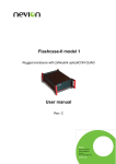
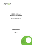
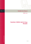
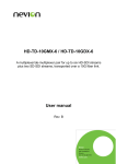
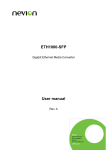
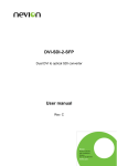
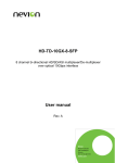
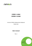
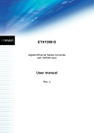
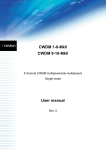
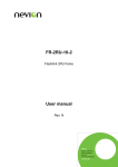
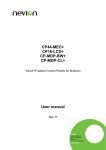
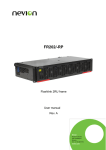
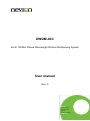
DWDM-40C 40-ch 100GHz Dense Wavelength Division Multiplexing System User manual Rev. A Nevion Nordre Kullerød 1 3241 Sandefjord Norway Tel: +47 33 48 99 99 nevion.com DWDM-40C Rev. A Nevion Support Nevion Europe Nevion USA P.O. Box 1020 3204 Sandefjord, Norway Support phone 1: +47 33 48 99 97 Support phone 2: +47 90 60 99 99 1600 Emerson Avenue Oxnard, CA 93033, USA Toll free North America: (866) 515-0811 Outside North America: +1 (805) 247-8560 E-mail: [email protected] See http://www.nevion.com/support/ for service hours for customer support globally. Revision history Current revision of this document is the uppermost in the table below. Rev. Repl. Date Sign Change description A 0 0 - 2015-06-10 2007-11-20 MB OEH Template update; Appendix A added New manual released nevion.com | 2 DWDM-40C Rev. A Contents Revision history ..................................................................................................................... 2 1 Product overview ................................................................................................................ 4 2 Specifications ..................................................................................................................... 5 2.1 Optical specifications for 40-channel system ................................................................... 5 2.2 Wavelength Chart according to ITU-T G.694.1 ................................................................ 6 3 Connections ....................................................................................................................... 7 3.1 Connecting to the DWDM-40C ........................................................................................ 7 3.2 System design ................................................................................................................. 7 4 Operation ........................................................................................................................... 8 4.1 Handling of optical fibers ................................................................................................. 8 4.2 Laser safety precautions.................................................................................................. 8 4.3 Connector cleaning.......................................................................................................... 9 4.4 Power dissipation in the DWDM-system. ........................................................................10 General environmental requirements for Nevion equipment .................................................12 Appendix A Materials declaration and recycling information .................................................14 A.1 Materials declaration ......................................................................................................14 A.2 Recycling information .....................................................................................................14 nevion.com | 3 DWDM-40C Rev. A 1 Product overview The Flashlink DWDM-40C is a set of optical modules for multiplexing and demultiplexing 100GHz spaced DWDM (Dense Wavelength Division Multiplexed) signals. The modules are bidirectional, so they work as both multiplexer and demultiplexer at the same time. A DWDM-40C consists of one DWDM-40C-A and one DWDM-40C-B, which when used together, provide an optimal link loss by stepping the insertion loss profiles in one end point complementary to the other. Figure 1: DWDM-40C block diagram nevion.com | 4 DWDM-40C Rev. A 2 Specifications 2.1 Optical specifications for 40-channel system Number of channels Available wavelengths Connector Insertion loss (per matched pair, including connectors) Channel Spacing Passband Adjacent Channel Isolation Non-Adjacent Channel Isolation Directivity Thermal Wavelength Stability Return loss PDL Operating Temperature Storage Temperature Optical Power 40 See section 0 SC/UPC 6dB max 100GHz ITU +/- 12.5GHz 25dB min (28dB typ.) 40dB min 45dB min 1.0 pm/oCmax 45dB min 0.25dB max 0 – 40 oC -40 – 85 oC 300mW max nevion.com | 5 DWDM-40C Rev. A 2.2 Wavelength Chart according to ITU-T G.694.1 Frequency [THz] 195,90 195,80 195,70 195,60 195,50 195,40 195,30 195,20 195,10 195,00 194,90 194,80 194,70 194,60 194,50 194,40 194,30 194,20 194,10 194,00 193,90 193,80 193,70 193,60 193,50 193,40 193,30 193,20 193,10 193,00 192,90 192,80 192,70 192,60 192,50 192,40 192,30 192,20 192,10 192,00 Wavelength [nm] 1530,33 1531,12 1531,90 1532,68 1533,47 1534,25 1535,04 1535,82 1536,61 1537,40 1538,19 1538,98 1539,77 1540,56 1541,35 1542,14 1542,94 1543,73 1544,53 1545,32 1546,12 1546,92 1547,72 1548,51 1549,32 1550,12 1550,92 1551,72 1552,52 1553,33 1554,13 1554,94 1555,75 1556,55 1557,36 1558,17 1558,98 1559,79 1560,61 1561,41 Red wavelengths ITU Channel No. 59 58 57 56 55 54 53 52 51 50 49 48 47 46 45 44 43 42 41 40 39 38 37 36 35 34 33 32 31 30 29 28 27 26 25 24 23 22 21 20 Blue wavelengths The following wavelengths/channels are in use for the 40 channel system DWDM-40C nevion.com | 6 DWDM-40C Rev. A 3 Connections 3.1 Connecting to the DWDM-40C Figure 2.11 shows the backplane for the flashlink 40-channel DWDM optical filter frame. Each optical port supports a dedicated wavelength that is marked on the sub-rack frame. The connector is an SC/PC connector. Each port should be connected to the corresponding wavelength for each channel card with an optical patch cord. The common port supports all wavelengths in either direction and should therefore be connected to the single fiber between the two locations where the flashlink 40-channel DWDM system is installed. The optical filters are sold in pairs using cascaded thin film filters for wavelength selection. This means that the filters are mounted in opposite orders on the two sides. Those wavelengths which have lower attenuation in one end point have higher attenuation in the other end point, thus ensuring all channels have the same link loss. The specification of the optical filters can be found in chapter 2. One side is marked DWDM-40C-A, the other is marked DWDM-40C-B. Figure 3.1: The backplane for the 40-channel DWDM system optical filter (endpoint A) 3.2 System design The maximum insertion loss for any channel in end point A is 4.0dB, but the same channel in the complementary end point B will then have a maximum insertion loss of 1.5dB. Likewise the channel with maximum allowed insertion loss of 1.5dB in endpoint A will have a maximum insertion loss of 4.0dB in end point B. This means that there can theoretically be about 3dB difference in attenuation between two different channels (1.5dB variance across the band) after multiplexing. When using erbium doped fiber optical amplifiers (EDFA), this can lead to large differences in signal strength between different channels at the receiving end. The reason is that EDFAs also have a variance in gain across the wavelength band. Therefore a special uniform loss version (suffix -U) is available as an option. EDFAs used with DWDM-40C should have a gain flattening filter and operate close to nominal gain / input power. When operating over or under nominal gain, the EDFAs gain variance changes drastically. The minimum headroom that needs to be considered when designing a system increases for each EDFA because of the gain variance across wavelengths. nevion.com | 7 DWDM-40C Rev. A 4 Operation 4.1 Handling of optical fibers This product includes fiber optic equipment. Access to the optical signal path is given through the optical connectors (see separate chapter). Even though a fiber optic cable can look almost the same as an electrical wire, special care must be taken. Inside the cable is a fiber made of glass. Glass has very different physical properties than the copper used in electrical wires. In practical terms this means that these precautions must be taken: Do not bend the fiber too much Do not put anything on top of the optical fiber. Keep the connectors clean from dust If a fiber is bent to much, parts of the transmitted light is lost or in worst case the glass is broken. All the datasheets of optical fibers have a point called "minimum bend radius". This means that any bending of the fiber corresponding to a bend radius less than the given value will make the light leak out of the fiber. A typical value is 20 mm to 40 mm (Telcordia standard) for single mode fibers. You should also avoid putting any heavy items on top of the optical fibers, because this will change the optical properties of the fiber, and contribute to errors in the transmitted signal. Unless the fiber is damaged, it will regain its optical properties after a bend is straightened out or the items are removed / the squeeze is released. 4.2 Laser safety precautions Guidelines to limit hazards from laser exposure. All the available EO units in the flashlink range include a laser. Therefore this note on laser safety should be read thoroughly. The lasers emit light at wavelengths around 1550 nm. This means that the human eye cannot see the beam, and the blink reflex cannot protect the eye. (The human eye can see light between 400 nm to 700 nm). nevion.com | 8 DWDM-40C Rev. A A laser beam can be harmful to the human eye (depending on laser power and exposure time), therefore: !! BE CAREFUL WHEN CONNECTING / DISCONNECTING FIBER PIGTAILS (ENDS). NEVER LOOK DIRECTLY INTO THE END OF THE FIBER. NEVER USE MICROSCOPES, MAGNIFYING GLASSES OR EYE LOUPES TO LOOK INTO A FIBER END. USE LASER SAFETY EYEWEAR BLOCKING LIGHT AT 1310 nm AND AT 1550 nm. Instruments exist to verify light output power: Power meters, IR-cards etc. The FR-2RU-10-2 is classified as Class 1 laser product according to EN 60 8251:94/A11:96, and CFR Ch1(1997) Part 1040.10. If the front panel is removed, the FR-2RU-10-2 is classified as Class 1 laser product according to EN 60 825-1:94/A11:96, and class IIIb according to CFR Ch1(1997) Part 1040.10. Maximum output power after multiplexing in DWDM-40C: 30mW Operating wavelengths: 1550 20nm. < 5mW >1270nm 4.3 Connector cleaning Optical connectors should be kept clean at all times. Whenever a connector is disconnected the enclosed protective dust cap should be put on. This protects the ferrule used for fiber alignment and prevents the surface from being scratched or damaged. nevion.com | 9 DWDM-40C Rev. A Figure 1.1: The different parts of an SC/PC connector Cleaning procedure: If the ferrule is dirty it must be cleaned before re-connection. If a clean connector is pressed against a dirty connector, both connectors will become dirty resulting in possible degradation of signal quality. Or even worse, you may damage the surface of the connector(s). We recommend that the cleaning procedure is done by using a special cleaning-tape suitable for this purpose, called CleTop (see picture below). 4.4 Power dissipation in the DWDM-system. Due to the need of very stable laser emission wavelengths, a precise temperature control of the laser cavity is needed. The laser wavelength will drift with changing temperature if the laser is not controlled. This means that the internal temperature of the laser must be kept at a constant level for all operation temperatures. This is done through the use of a Peltier element placed within the laser package. The function of the Peltier element is to control the temperature in a similar way as a refrigerator. If the ambient temperature increases the Peltier element will cool the inside of the laser package to keep the temperature at a constant level. If the opposite is the case and the ambient temperature decreases, the Peltier element will heat the inside of the package to keep the internal temperature constant. The quantity of heat absorbed or produced is proportional to the current flowing through the contact. In practical terms this means that the nevion.com | 10 DWDM-40C Rev. A current is proportional to the temperature difference between the ambient temperature and the desired temperature within the laser package. If the ambient temperature is lower than the package temperature, the power dissipated will support the heating process of the device by increasing the ambient temperature. On the other hand, if the ambient temperature is much higher than the desired package temperature (about +22°C) it may cause the laser to malfunction. The current, which is proportional to the temperature difference, implies power dissipation and an increase of the ambient temperature. This increased ambient temperature will again increase the current through the Peltier element in order to lower the internal package temperature. The increased current will make more power dissipate thereby increasing the ambient temperature, and so on. To avoid this, proper ventilation of the DWDM-system is needed. A 40-channel system needs 12RU-26ru of rack space. Additional rack space needed for ventilation is 1RU above and below each set of 4 flashlink frames (8RU). Receiver cards generate less heat than transmitter cards, and bidirectional cards decrease the number of cards in a 40-channel system. Please consult with Network Electronics before building a 40-channel system. Example with 6 flashlink frames, frame space utilisation depending on card types: 1RU 6RU 1RU 2RU 1RU 6RU 1RU Fan, hot air exhaust 3x flashlink DWDM frames Cold air intake flashlink DWDM filter frame Fan, hot air exhaust 3x flashlink DWDM frames Cold air intake The operational temperature for the DWDM-system is 0°-40°C. nevion.com | 11 DWDM-40C Rev. A General environmental requirements for Nevion equipment 1. 2. 3. - The equipment will meet the guaranteed performance specification under the following environmental conditions: Operating room temperature range: 0°C to 40°C Operating relative humidity range: <90% (non-condensing) The equipment will operate without damage under the following environmental conditions: Temperature range: -5°C to 50°C Relative humidity range: <95% (non-condensing) Electromagnetic compatibility conditions: Emissions: EN 55103-1 (Directive 89/336/EEC) Immunity: EN 55103-2 (Directive 89/336/EEC) Electrical safety: EN 60 950 With reference to the declaration of conformity provided with the external power supply. nevion.com | 12 DWDM-40C Rev. A Product Warranty The warranty terms and conditions for the product(s) covered by this manual follow the General Sales Conditions by Nevion, which are available on the company web site: www.nevion.com nevion.com | 13 DWDM-40C Rev. A Appendix A Materials declaration and recycling information A.1 Materials declaration For product sold into China after 1st March 2007, we comply with the “Administrative Measure on the Control of Pollution by Electronic Information Products”. In the first stage of this legislation, content of six hazardous materials has to be declared. The table below shows the required information. Toxic or hazardous substances and elements 組成名稱 Part Name DWDM-40C 鉛 汞 镉 六价铬 多溴联苯 Lead Mercury Cadmium Hexavalent Polybrominated (Pb) (Hg) (Cd) Chromium biphenyls (Cr(VI)) (PBB) O O O O O 多溴二苯醚 Polybrominated diphenyl ethers (PBDE) O O: Indicates that this toxic or hazardous substance contained in all of the homogeneous materials for this part is below the limit requirement in SJ/T11363-2006. X: Indicates that this toxic or hazardous substance contained in at least one of the homogeneous materials used for this part is above the limit requirement in SJ/T11363-2006. This is indicated by the product marking: A.2 Recycling information Nevion provides assistance to customers and recyclers through our web site http://www.nevion.com/. Please contact Nevion’s Customer Support for assistance with recycling if this site does not show the information you require. Where it is not possible to return the product to Nevion or its agents for recycling, the following general information may be of assistance: Before attempting disassembly, ensure the product is completely disconnected from power and signal connections. All major parts are marked or labeled to show their material content. Depending on the date of manufacture, this product may contain lead in solder. Some circuit boards may contain battery-backed memory devices. nevion.com | 14