1
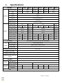
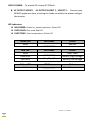
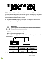
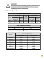
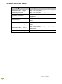
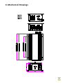
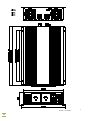
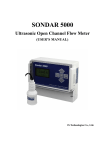
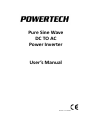
Pure Sine Wave DC TO AC Power Inverter User’s Manual Version 1.3-130603 0 Contents 1. Specifications …………………………………………………………..........2 2. Important Safety Guidelines and Instructions……………….……3~4 3. Features…………………………………………..………………..….....4 4. Applications and Descriptions……………………..………..……..…..5 5. Introduction and Operation ……………………………..…..….6~14 6. Mechanical Drawings…………………………………….….…....15~18 7. Trouble Shooting……………………………………….......................19 8. Maintenance……………………………………………..…….............19 9. Warranty………………………………………………..………............20 1 1. Specifications: MODEL: OUTPUT MI5700 MI5702 MI5703 MI5704 MI5706 MI5708 MI5710 MI5712 Continuous output 180W 360W 800W 1100W 1500W 2000W Surge 360W 720W 1600W 2200W 3000W 4000W Voltage AC230V Frequency 50Hz Waveform Pure Sine Wave(THD<3%) Regulation (Typ.) Vrms <±3% USB Output (Typ.) DC 5V ± 5% Battery Voltage DC Current (Typ.) 12V 20A 500mA 24V 40A 12V 20A 80A 24V 120A 160A 220A 110A Low Battery Alarm 10.6±0.2V 21.2±0.3V 10.6±0.2V 21.2±0.3V Low Battery Protection 10±0.2V 20±0.3V 10±0.2V 20±0.3V High Battery Protection 15±0.2V 30±0.3V 15±0.2V 30±0.3V INPUT No Load Current 0.35A 0.4A 0.2A 0.5A 0.75A 0.85A 0.95A 0.5A Stand-by Current 0.08A 0.1A 0.05A 0.15A 0.18A 0.2A 0.2A 0.15A Efficiency (Typ.) 89% 90% 92% 91% 91% 91% 91% 93% Protection High Temperature ; Short-Circuit ; Over Load ; Input Voltage Load 95~100% Alarm but remain working Load 105% Alarm then after 1 minute shut down Load 120% Alarm then after 5 seconds shut down Load Control Operating temperature range -20℃ ~ 40℃ Operation Humidity 20 ~ 90% RH Storage Temp Humidity -30℃ ~ 70℃, 10~90% RH Intelligent Design Heat Auto Fans slow speeding up 38℃±3,Fans start speeding up:42℃±3 Control High Temperature Shut Down : 65℃±3,Restart Output: 56℃±3 Indicator Inverter : Green LED / Soft Start-up Over Load : Red LED / Over Temperature : Yellow LED Soft Started Function Others Remote Controller NO YES D*W*H(mm) 186x117x57 230x118x57 Weight(kg) 0.85kg 1.05kg 295x165x57 364x180x74 350x230x74 450x230x74 Mechanical Note 1.9kg 3.6kg 4.2kg Efficency test done at approx 75% load, with 13V input for 12V model, 26V input for 24V model Note: The specifications are subject to change without prior notice. Version 1.3-130603 2 5.5kg WARNING! Before using the inverter, read and save the safety instructions carefully. 2. Important Safety Guidelines and Instructions To avoid danger of electric shocks, fire, injury when using electrical equipment, please read this manual carefully before installing and starting up. This instruction manual should be carried with the device and stored in a safe place. Failure to observe this instruction can cause material damage, device malfunction or danger of injuries. Fundamental safety measures should be observed when using electrical equipment. 2-1. General Safety and installation Precautions Do not expose the inverter to water, snow, spray, or dust. Keep the inverter in a dry, cool, clean and ventilated place. To reduce risk of hazard, do not cover or obstruct the ventilation ports or fans. Do not install the inverter in a zero-clearance compartment. Overheating may occur. The inverter must be kept in a safe place out of the reach of children. Make sure that the device is properly secured. To avoid a risk of fire and electronic shock, make sure that existing wiring and terminations are in good electrical condition, secure and not undersized. Do not operate the inverter with damaged or substandard wiring. If the fuse blows or protection fails, parts of the inverter remain functional. Only qualified personnel should carry out maintenance or repair work as some components in the inverter can hold very high voltages even after being turned off. To prevent fire or explosion, do not put batteries, flammable materials, or anything that has to be ignition-protected around the inverter. Do not reverse the polarity of the DC input connections, as this may cause permanent damage to the inverter. Make sure the (+) and (-) cables from the battery are connected to the corresponding terminals of the inverter. Always disconnect the inverter when not in use. To prevent electrical shock, do not operate without connecting the inverter to ground. 3 Precautions When Working and Operating with Batteries 2-2. Never smoke or produce sparks or flame in the vicinity of the battery or the engine. If battery acid contacts skin or clothes, you shall wash it out with soap and water immediately. If battery acid contacts your eyes, you shall wash it out with cold running water for at least 20 minutes and get medical attention immediately. Make sure the power plug is firmly connected in the socket. If the connection is not firm enough, the plug will heat up and cause damage to device. Do not start the engine while the inverter is on, this may cause inverter to shut down. The inverter can be operated with the engine running or off. If it is necessary to operate the device for a long time, start the engine to recharge the vehicle battery. Do not drop or place metal tools on the battery. The spark or short-circuit on the battery of other electrical part may cause an explosion. Remove personal metal items such as rings, bracelets, necklaces, and watches when operating with lead-acid batteries. These are electrically conductive devices and may cause short circuit and very high temperature, resulting in personal injury. USB supply output DC 5V 500mA. 3. Features Pure Sine Wave output with THD<3% Advanced microprocessor design Soft Start Function : High surge capacity for starting demanding loads High efficiency up to 93% on high power models Input and Output electrically isolated Multi-stage power saving mode : conserve energy with green power Multi-stages intelligent cooling system Intelligent output overload protection : Load 95~100% alarm sounds but remains working Load 105% alarm sounds, then after 1 minute shut down Load 120% alarm sounds, then after 5 seconds shut down Suitable for resistive, capacitive, and inductive loads Full protection : output short circuit, input high/low voltage, temperature Wired remote control included with higher power models Version 1.3-130603 4 4. Applications and Descriptions Compared to a commercial grade Modified Sine Wave Power Inverter, the output of Pure Sine Wave inverters are more suitable for sensitive electronic equipments. Pure Sine Wave Inverters produce power which is identical to, and in most cases better than the power from the public utility power grid system. Industrial equipment-metal halide lamp, high-pressure sodium lamp, etc. Power tools-circular saws, drills, grinders, sanders, buffers, weed and hedge trimmers, air compressors, etc. Office equipment-computers, printers, cash registers, monitors, facsimile machines, scanner, etc. Household appliances-vacuum cleaners, fans, fluorescent and incandescent lights, shavers, sewing machines. Kitchen appliances-coffee makers, small refrigerators, blenders, ice markers, toasters, etc. Home entertainment electronics-television, VCRS, BlueRay/DVD players, radios, video games, stereos, musical instruments, satellite equipment, etc. USB 5V DC is for-digital camera, cell phone, video game, MP3, MP4, PDA 5 5. Introduction & Operation Please read the instructions carefully before you install and operate the inverter. This power inverter series is one of the most advanced and high-quality types available. To get the most optimum power from the inverter, it must be installed and used properly. The AC output voltage corresponds to the standard pure sine wave as supplied by energy authorities (as per AS 60038). 5-1. Inverter Operation: Make sure the inverter power switch is in the OFF position. Connect the inverter to a fully charged battery. Use the “ON/OFF” switch to turn the inverter ON or OFF. Connect the electric appliance to AC output socket of the inverter. Turn the inverter “ON” – the Green LED should light up, indicating power is on and inverter is functional. Appliance can now be used. When finished, turn inverter power switch to “OFF” position, this will shut down the inverter When using wired remote controller make sure the inverter “ON/OFF” Switch is in the “ON”position. 5-2. Front Panel Operations I NV. POWER/ OVER. LOAD OVER. TEMP ON 1 2 3 4 MI5704 Version 1.3-130603 6 MI5708 MI5710 MI5712 ON/OFF: Power switch Remote: Input terminal of wired remote control. Make sure the power switch is turned to the “ON” position. The remote only controls the power of the inverter (ON/OFF). Power Saving Mode: Power Saving Mode is adjustable and set by the Dip Switch, SW1 and SW2. Setting this mode reduces the inverter’s standby power consumption if the applied AC load is below the set threshold in the table below. After setting the DIP switches, you must restart the inverter. MI5700 MI5702 MI5703 MI5704 MI5706 MI5708 MI5710 MI5712 No Saving No Saving 20W 30W 50W 100W No Saving 20W SW1 SW2 OFF OFF ON ON OFF ON OFF ON Noted: these are nominal values only and may vary. 7 USB 5V 500MA: To provide DC output 5V 500mA. AC OUTPUT SOCKET: AC OUTPUT SOCKET 1 , SOCKET 2 : Connect your 230VAC appliances here, ensuring the loads are within the power rating of the inverter. LED Indicators: INV.POWER: Power on, normal operation. Green LED OVER LOAD: Over load, Red LED OVER TEMP.: Over temperature, Yellow LED Green LED Solid LED Show __________ Status Normal Red LED Solid Slow Blink Fast Blink LED Show __________ __ __ __ - - - - - Status Over Load Battery High voltage Battery Low voltage Yellow LED Solid LED Show __________ Status Over Temperature Version 1.3-130603 8 5-3. Rear Panel Operations R SONDAR R SONDAR R SONDAR R SONDAR 9 R R SONDAR SONDAR FAN Ventilation: Make sure there is a minimum clearance of 30cm from the fan grilles to allow adequate airflow into the inverter for cooling. Do not mount the inverter in a completely sealed enclosure. The enclosure should also have ventilation ports to allow adequate airflow. DC Input Terminals: Connect DC terminals to a battery (or battery bank) with appropriate voltage for the inverter being used. WARNING! Reverse polarity connection will blow the internal fuse and may damage the inverter permanently. POS +: Represents positive terminal NEG - : Represents negative terminal Connect the (+) and (-) cables from the battery to the respective terminals of the inverter MODEL 12V 24V DC Input voltage Minimum Maximum 10.1V 15V 20.1V 30V Ground connection: Use wire(>#12) to connect chassis ground Version 1.3-130603 10 WARNING! Operating the inverter without a proper ground connection may cause an electrical hazard. Refer to relevant wiring standards or consult a professional. 5-4. Features of protection: DC Input Voltage Protection: Over Voltage Model 12V 24V High voltage Shut-down 15.1V 30.1V Restart Low Voltage Alarm 14.5V 29V 10.6V 21.2V Low Voltage Low voltage Shut-down 10V 20V Restart 12.5V 25V Over Temperature Protection: 65℃ Shut-down Model 56℃ Restart Over Load Protection: 1 min. Shut-down 5 sec. Shut-down MI5700 190W 220W MI5702 380W 430W MI5703 380W 430W MI5704 820W 950W MI5706 1250W 1320W MI5708 1600W 1800W MI5710/MI5712 2100W 2400W 11 5-5. Buzzer Alarm Fault Status: Fault Type: Sound Signal Sound Symbol Low Battery Alarm,Stage 1 “BEEP” two times slowly -- Low Battery Protection “BEEP” two times fast -- -- -- -- -- “BEEP” two times fast ―― ―― ―― High Battery Protection Heat Protection Load Control Alarm,Stage 1 Load Control Alarm,Stage 2 Load Control Alarm,Stage 3 -- (long beeps) “BEEP” one time (long __ __ __ beeps) “BEEP” three times --- --- Slowly “BEEP” three times at --- --- --- medium rate “BEEP” three times fast --- --- --- --- Version 1.3-130603 12 __ 5-6. Installation: The power inverter should be installed in an environment that meets the following requirements. Dry --- Do not allow water to drip on or enter into the inverter. Cool --- Ambient air temperature should be between 0℃ and 40℃, the cooler the better. Safe --- Do not install the inverter in a battery compartment or other areas where flammable fumes may exist, such as fuel storage areas or engine compartments. Ventilated --- Keep the inverter at least 10cm away from surrounding objects, and at least 30cm from fans. Ensure the ventilation slots on the rear and the bottom of the unit are not obstructed in any way. Dust --- Do not install the inverter in a dusty environment. Dust can be drawn into the unit when the cooling fan is working and cause damage to the circuits. Close to batteries --- Avoid excessive cable lengths. Do not install the inverter in the same compartment as batteries. Use the recommended wire lengths and sizes. Do not mount the inverter where it will be exposed to the gases from the batteries, as prolonged exposure will damage the inverter. WARNING! Shock Hazard. Before proceeding, carefully check that inverter is NOT connected to any batteries, and that all wiring is disconnected from any electrical sources. NEVER connect the AC output terminals of the inverter to an incoming AC source such as mains, or an AC generator. 5-7. DC Wiring Connections: Follow this procedure to connect the battery cables to the DC input terminals of the inverter. The DC cables should be as short as possible (less than 3 meters) and large enough to handle the required current in accordance with the electrical codes or regulations applicable to the installation. Cables that are too small in gauge (too thin) or too long will drastically reduce inverter performance, causing poor surge capability and frequent 13 low-input voltage warnings and shutdowns. This is due to the DC voltage drop in the cables from the battery to the inverter. The longer and narrower the cables, the greater the voltage drops. WARNING! DC wiring terminations. Ensure all the DC connections and terminations are secure and tight. Loose connection can cause overheating and fire. The following table recommends the cable size for optimum inverter performance. SU Series Wire AWG Inline Fuse MI5703 #12 25A MI5702 #10 25A*2 MI5704 #6 30A*4 MI5712 MI5706 MI5708 MI5710 #4 #2 #1 25A*6 30A*6 30A*8 25A*12 Description Black 1M + Red 1M Lay the flexible earth cable from the earthing point of the vehicle to the earthing point of the inverter. If cables are to be fed through metal walls or walls with sharp edges, use glands or proper bushings to prevent cable damage. Do not lay cables that are loose or bent next to electrically conductive materials. Version 1.3-130603 14 6. Mechanical Drawings SONDAR R SONDAR R I NV. POWER/ OVER. LOAD OVER. TEMP 15 SONDAR R Version 1.3-130603 16 17 R SONDAR Version 1.3-130603 18 . Trouble Shooting: WARNING! Do not open or disassemble the inverter. Attempting to service the unit yourself may cause the risk of electrical shock or fire. Problems and Symptoms Does not turn on Possible Cause Solutions Change battery, check DC cables and terminations No AC power output. Red LED always on Battery damaged, or bad DC cable connection Output overload or short circuit No AC power output. Red LED blink slowly Low battery voltage or high battery voltage No AC power output. Yellow LED blink slowly Over temperature shut-down Check battery voltage, charger battery, check DC cable terminations Check if there is proper ventillation. Check if there are any objects or barriers blocking the vents or fans Decrease load, check AC cable. Remove load, check output 8. Maintenance: To keep your inverter operating properly, there is very little maintenance required. Make sure the inverter is switched OFF. Clean the exterior periodically with a cloth to prevent accumulation of dust and dirt. Do not use sharp or hard objects to clean, these may damage the device. Check the DC cables and terminations, making sure they are secure and tight. 19 9. Warranty Your Powertech pure sine wave inverter comes with a 2 year warranty that commences from the date of purchase, under the following conditions: • That all defects are attributable to material or production defects/errors and not improper use (warranty is void if the unit is improperly used, improperly installed or damaged through negligence) • The warranty claim is made within the warranty period (proof of purchase required) • Any unit covered under warranty will be repaired or replaced at the discretion of the distributor, after being assessed by the distributor and deemed a defect covered by warranty • Units claimed under warranty will be returned to Head Office in Rydalmere NSW, for assessment. Where a false warranty claim is made, the customer will bear costs of the unit being returned to them. • Warranty does not cover parts such as external case, fuses, connectors, input leads, etc Our goods come with guarantees that cannot be excluded under the Australian Consumer Law. You are entitled to a replacement or refund for a major failure and compensation for any other reasonably foreseeable loss or damage. You are also entitled to have the goods repaired or replaced if the goods fail to be of acceptable quality and the failure does not amount to a major failure. To make any claim under warranty, please return your unit with proof of purchase, to your original place of purchase. Your original place of purchase will be able to handle the warranty claim with the distributor on your behalf. Where this is not practicable, please contact Electus Distribution directly with the below contact details, and you will be advised on the best way your warranty claim can be handled. Australia – Contact ph. 1300 738 555, or email [email protected] New Zealand – Contact ph. 0800 235 328, or email [email protected] Version 1.3-130603 20