1
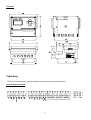
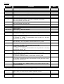
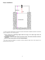
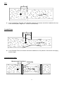
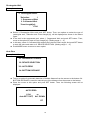
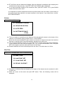
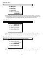
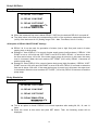
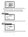
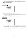
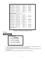
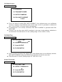
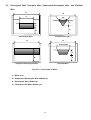
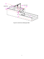
SONDAR 5000
Ultrasonic Open Channel Flow Meter
(USER’S MANUAL)
IS Technologies Co., Ltd.
SONDAR 5000
May.2004 Edition
COPYRIGHT
© IS Technologies Co., Ltd. All rights reserved. No part of this publication may be reproduced, transmitted,
transcribed, stored in a retrieval system, or translated into any language in any form without the written permission
of IS Technologies Co., Ltd.
WARRANTY AND LIABILITY
IS Technologies Co., Ltd. guarantees for a period of 1 year from the date of delivery that it will either exchange or
repair any part of this product returned to IS Technologies Co., Ltd. if it is found to be defective in material or
workmanship, subject to the defect not being due to unfair wear and tear, misuse, modification or alteration,
accident, misapplication or negligence.
DISCLAIMER
IS Technologies neither gives nor implies any process guarantee for this product, and shall have no liability in
respect of any loss, injury or damage whatsoever arising out of the application or use of any product or circuit
described herein.
Every effort has been made to ensure accuracy of this documentation, but IS Technologies cannot be held liable
for any errors.
TECHNICAL ENQUIRIES
Please contact IS Technologies Co., Ltd. for technical support.
IS Technologies Co., Ltd.
203/504 Buchon Techno Park, 192, Yakdae Dong, Wonmi Gu, Buchon City, Kyungki, Korea
Tel: 82-32-621 2606
Fax: 82-32-621 2612
Web Site: http://www.sondar.com
e-mail: [email protected]
2
Table of Contents
Chapter 1 Introduction..........................................................................................................................................................4
About Sondar 5000 ...............................................................................................................................................................4
Features of of Sondar 5000… ..............................................................................................................................................5
Product Specification….........................................................................................................................................................6
Chapter 2 Installation............................................................................................................................................................7
Dimensions ............................................................................................................................................................................7
Cable Entry ............................................................................................................................................................................8
Sensor Installation… ...........................................................................................................................................................10
Chapter 3 How To Use Sondar5000 ...............................................................................................................................13
Operating the Controller......................................................................................................................................................13
Button Functions..................................................................................................................................................................14
Chapter 4 Menu Guide.......................................................................................................................................................15
Applicaton Menu Option......................................................................................................................................................15
Proces Menu Option............................................................................................................................................................25
Compensation Menu Option...............................................................................................................................................33
Chapter 5 Maintenance..........................................................................................................................................................37
Chapter 6 Menu Option Record.........................................................................................................................................38
Appendix ..............................................................................................................................................................................39
3
Chapter 1 Introduction
About SONDAR 5000
Sondar 5000 is an instrument that can be used both as ultrasonic open channel flow meter
and level gauge. The ultrasonic open channel flow meter measures the water level and
calculates and displays accurate flow rate and total flow rate in a manner to measure the flow
rate according to a flow/level calculation method, based on the principle that water level is
specifically related to flow rate in the standardized open channel.
The ultrasonic flow meter employing non-contact measurement method can be applicable to
various fluids, including corrosive fluid, and has semi-permanent life.
Data Logger function is built in this product, enabling long-term storage of various data, such
as level, flow rate, and total flow rate. These data can be saved for up to 6 months.
This product can be applicable to the following open channels.
1. Parshall Flumes
2. Suppressed Rectangular Weirs
3. Contracted Rectangular Weirs
4. V-Notch [Triangular] Weirs. [22.5°, 30°, 45°, 60°, 90°, 120°]
5. Cipolletti Weirs
6. Leopold Lagco Flumes
7. Palmer Bowlus Flumes
In addition, 10 point DIY CURVE and flow equation (Q=K*H(PWR)) are used to measure the
flow rate in various open channels.
4
Features of SONDAR 5000
z Non-contact flow measurement - applicable to various fluids, semi-permanent life
z Applicable to various kinds of channels
z 10 point DIY CURVE function able to conduct flow measurement, regardless of the
types of channels
z Digital measurement and display (0.01 m3/h)
z Current output in proportion to flow measurement (4mA ~ 20mA)
z Flow rate setting at 4mA ~20mA
z Flow-based pulse output (able to set unit flow rate) - applicable to mechanical flow
meter
z 2 programmable SPDT relays
z 5 buttons for convenient and easy operation
z LCD to display operational conditions - convenient setting
z Built-in temperature sensor and temperature compensation function
z Ultrasonic output adjustment and algorithm selection assuring consistent flow
measurement
z Automatic detection of bottom distance
z Storage of various data, including water level, flow rate, and total flow rate, for up to 6
months.
z Flow Switch input function able to measure the flow rate at Zero flow [Option]
z Operation with free voltage power, low power consumption
5
Product Specification
Physical
Controller
240(width). X 185(height) mm
Sensor
Ø 67(dia) X 160(height) mm
Mounting
3/4” NPT
Weight
around 3.0kg (sensor, controller)
Polypropylene
Sensor Material
Environmental
IP Rating (electronics housing)
IP65(Controller)
Max. & Min. temperature (electronics)
-20 ºC to +60 ºC(Controller), -20 to +70°C(Sensor)
10m (Standard)
RTX cable length
Performance
Resolution
1mm
Range(Flow rate)
3
3
0.00m /h ~ 200,000.00 m /h
Range(Total flow)
3
999999999.99 m /h
Range(level)
250 ~ 8000mm
Beam Angle
o
8 at -3dB
Response Time
500ms
Displayed Value
Flow rate, Total flow, Level , graphic LCD (128X68 dot)
Temperature Compensation
Fully compensated via integral temperature sensor over entire operational span
Outputs
Analogue Output
4-20mA into Max 600Ω (user adjustable)
Fault condition Alarm 3.8mA /Hold/21mA,
Setpoint Relay
3 SPDT Relays
Relay capacity
5A, AC250V
Communication Port
1 point RS-232C/RS485
Pulse output
1 point, open collector or line drive
Programming
On-board programming
via 5 tactile push button buttons
Supply
Power supply
AC90 ~ 260V, Less than 15VA(50Hz ~ 60Hz),
Applicable Channel
15 kinds of Parshall Flumes
Suppressed Rectangular Weirs
Contracted Rectangular Weirs
V-Notch[Triangular] Weirs.[22.5°, 30°, 45°, 60°, 90°, 120°]
10 kinds of Cipolletti Weirs
10 kinds of Leopold Lagco Flumes
10 kinds of Palmer Bowlus Flumes
Special function
10 Point DIY CURVE
Flow equation(Q=K*H(PWR))
6
Chapter 2 Installation
Sondar 5000 is composed of a controller unit and one sensor
Power Supply Requirements
The Sondar 5000 operates from a AC supply of 90 ~260V.
All electronic products are susceptible to electrostatic shock, so follow proper grounding
procedures during installation.
When choosing a location to mount the sensor, bear in mind the following:
• For easy access to the LCD display and programming buttons mount it where it is easily
accessible.
• The ultrasonic signal path should be free of falling material and obstructions such as pipes,
beams etc.
• The sensor should be mounted at least 30cm above the maximum level of the material and
be perpendicular to the surface.
• The mounting surface should be vibration-free.
• The ambient temperature of the sensor is between -20ºC and 70ºC.
• There should be no high voltage cables or electrical inverters close by.
Dimensions
Sensor
3/4" NPT
160
144
75.5
63.5
67
7
Controller
MODE
SET
RUN
Cable Entry
There are 23 terminals for controller and 3 terminals for power board as follows:
Input & Output Terminal
PULSE
RTN
PULSE
OC
IRTN
IOUT
GND
RX
TX
RTN
VIN
RTH
TX_CLK
SEN+
SEN-
V+
8
A1_COM
A2_COM
ER_COM
A1_NO A1_NC A2_NO A2_NC ER_NO ER_NC
L
N
Function
Terminal
V+
SENSEN+
TX CLK
RTH
VIN
RTN
TX
RX
Function
DC +12V output
Connect to shield cable of sensor of RTX
Connect to +cable of sensor of RTX
Output of sensor’s transmitting signals in pulse form
Connect to outer temperature sensor
External Input[FOLW SWITCH]
External input GND
When using RS232C interface, connection to RS232C's receiver.
When using RS485, connection to Z.
Digital communication GND
IOUT
Current output (+): Output of 4 mA ~ 20 mA in proportion to flow rate
IRTN
Current output (-)
PULSE OC
Pulse output (+): at the set intervals
PULSE RTN
Pulse output (-)
A1_COM
ALARM_1 COM contact point.
On operation of ALARM_1, disconnection from A1_NO & on its stop,
disconnection from A1_NC
ALARM_1 NC contact point.
When ALARM_1 is not in operation, disconnection from A1_COM
A2_NO
ALARM_2 NO contact point.
On operation of ALARM_2, disconnection from A2_COM
ALARM_2 COM contact point.
On operation of ALARM_2, disconnection from A2_COM & on its stop,
disconnection from A2_NC
A2_NC
ALARM_2 NC contact point.
When ALARM_2 is not in operation, disconnection from A2_COM
ER_NO
ERROR_NO contact point.
On operation in ERROR situation, disconnection from ER_COM
ER_COM
ER_NC
Max. 600Ω
ALARM_1 NO contact point.
On operation of ALARM_1, disconnection from A1_COM
A1_NC
A2_COM
Black
Red
Option
When using RS232C interface, connection to RS232C's transmitter.
When using RS485, connection to Y.
GND
A1_NO
Note
ERROR_COM contact point.
On operation in ERROR situation, disconnection from ER_NO & on its stop,
disconnection from ER_NC
ERROR_NC contact point.
When not operated even in ERROR situation, disconnection from ER_COM
L
AC power connection
N
AC power connection
* The below points are useful when test the Sondar5000 in field.
THR
DET
TVG
Output of standard voltage that determines the volume of the ultrasonic
signal. Users can check the most suitable installation location.
Output voltage of the detected ultrasonic signal
Output of amplified voltage of the ultrasonic signal. Trigger source of DET
signal
9
Test Point
Test Point
Test Point
Sensor Installation
Min 30cm
10°
Less than 8m
In order to prevent malfunctions and assure accurate measurement, installation should be conducted
under consideration of the following points.
1) There should be no disturbing objects within the range of 10°beam angle where the
ultrasonic pulse moves.
2) It should be installed at right angles to the water surface. (The sensor should be vertical to
the floor.)
3) Input accurate bottom distance (04. BOTTOM DISTANCE).
The sensor should be installed at a position of above maximum water level of the channel to be
measured (more than 30 cm).
10
Weir
L
Flow
z
In the rectangular, triangular, and Cipolletti channels, the sensor should be installed at the top
of the channel (Max. height x 4 ~ 5 times recommended).
Parshall Flume
L
2/3 L
Flow
Flow
z
In the Parshall Flume, the sensor should be installed at a 2/3 position of the whole converging
section length.
Leopold Lagco Flume
Measurement Point [mm ]
Converging
Flow
11
Flow
z
In the Leopold-Largco Flume, the sensor should be installed at a position distant from
Converging Section (corresponding to the distance of measurement point according to Flumes
size)
Flume Size
mm
100 ~
380
455
530
610
760
Measurement Point
inches
4~12
15
18
21
24
30
mm
25
32
38
44
51
64
inches
1.0
1.3
1.5
1.8
2.1
2.5
z
Flickering of "DT" at the bottom of the screen at Operation Mode means detection of water level.
Therefore, such flickering should be confirmed in the course of installation.
z
Installation should not be done at places exposed to direct sunlight or strong wind.
z
After installation, operational conditions should be checked again (Power On/Off and display of
measurement level).
※ Note: If not correctly installed, this product may not desirably work in the winter when
temperature difference between the sensor and the water surface is high.
12
Chapter 3 How To Use SONDAR 5000
Operating the controller
Sondar 5000
Flow Rate:
[GPM]
12345.6
MOD
SET
RUN
Lev. : 1 . 2 3 4 ft
R1
R2
SYSTEM OK
DT
Ultrasonic Open Channel Flow Meter
Operation Mode I
z
z
z
Push SET button at Operation Mode I and Operation Mode II will be displayed. Operation
Mode II can be toggled to Operation Mode I by SET button.
To see MGD(millions gallons per day)unit information, you can simply press UP button at
Operation Mode I
You can choose Operation Mode I or II as you want.
Sondar 5000
JUL / 21 / 2003
14:30
FR: 123456.78 GPM
TF: 123456789
mgal
TH: 123456789
h
DT: 12345678
mgal
DH:
DL:
Lev.: 0.000ft T:
%
MOD
SET
RUN
°F
Ultrasonic Open Channel Flow Meter
Operation Mode II
13
z Description of abbreviations displayed
1) FR : Flow rate measured in m3/h.
2) TF : Total flow from the set time.
3) TH : Total hours from the set time.
3) LE : Measured level from the bottom to the surface in mm.
4) T : Ambient temperature.
5) Bar graph: Ratio of measured flow rate to max. flow rate.
z Description of characters displayed
SONDAR 5000 shows its operational conditions on its LCD.
1) A1 : RELAY1 is ON.
2) A2 : RELAY2 is ON.
3) SYSTEM OK : System is normal.
4) FAIL: Failure to measure the flow rate.
5) DT: Flickered on normal measurement of water level.
(meaning normal detection of reflected waves)
6) D: Echo detection is okay
7) S: Searching Echo
8) LE: On failure to detect the reflected waves.
Button Functions
1) MODE Button
z To convert Operation Mode to Program Mode.
z Push MODE button at Operation Mode and PASSWORD CHECK, the first menu of Program
Mode, will be displayed.
z Push SET button and Program Mode will be immediately shown.
z At Program Mode, push Up or Down button to move to other menu option.
z Use MODE button to return to menu option after device selection (02. DEVICE SELECTION)
2) UP [↑] and DOWN [↑] Button
z Use this button to change the value of an option selected.
z One push of these buttons leads to increase by one. Continuous push of these buttons results
in continuous increase one by one. Further push of this button results in change of the number
at tenth or hundredth figures.
z If a specific menu is not selected, this button can be used to change menu options. One push of
this button results in return to the previous menu.
3) SET Button
z Use this button to save the values of an option and then, go to the next option selection.
4) RUN Button
z Use this button to return to Operation Mode from Program Mode.
14
Chapter 4 Menu Guide
Application Menu Option
Password Check
PASSWORD
CHECK
PASSWORD
CHECK
Password Number?
****
PASSWORD OK!
< When password is confirmed >
Password Number?
****
PASSWORD WRONG
RETURN MEASURE MODE
< When password is not confirmed >
z
Push MODE button at Operation Mode and PASSWORD CHECK, the initial menu of
Program Mode, will be displayed. This is a function to prevent change of set values by
unauthorized persons.
z
If the password is wrong, "PASSWORD ERROR!" and "RETURN MEASURE MODE" will be
displayed at the same time and it will return to Operation Mode.
z
If the password is confirmed, "PASSWORD OK!" will be displayed and it will go to Program
Mode.
z
The password can be changed at PASSWORD CHANGE. The password numbers can be
selected within the range of 0~1000.
z
Use ↑ or ↓ to move to a specific menu. Place the cursor (*) at a specific menu and push SET
button. Then, you can change the value of the menu.
z
If you don't want to change the value, push SET button and then, select another menu option.
z
If you want to change the value, push ↑ or ↓ to change it. After change, push SET button to
save the set value and then, select another menu.
z
If you push RUN in the course of selecting an option, Program Mode is converted into
Operation Mode.
15
Password Change
Factory Set= 0
*01. PASSWORD CHANGE
02. DEVICE SELECTION
03. AUTO ZERO
04. BOTTOM DISTANCE
z
z
z
This is an option for change of password. Push ↑ or ↓ to change the password.
Push SET button and the changed password will be saved.
The initial value is 0. (Setting range: 0~1000, Unit: 1)
※Note: If the password is wrong, you cannot go to Program Mode from Operation Mode.
Therefore, careful attention should be paid to password change. When you forget
the password, please contact the local distributor.
Device Selection
Factory Set = 1
01. PASSWORD CHANGE
*02. DEVICE SELECTION
03. AUTO ZERO
04. BOTTOM
z
z
This is an option for channel selection and detailed parameter setting. Select the channel first
and then, set parameters for the channel.
Place the cursor at this menu. Push SET button and the following screen I will be displayed.
The initial value is 1. (Setting range: 1~8, Unit: 1)
*** DEVICE :
*** DEVICE :
1) - 6
1) - 6
5. Cipoletti Weirs
*1. Parshall Flumes
2. Rect. Suppressed
6. Leoplod Lagco Flume
3. Rect. Contracted
7. Palmer Bowlus Flume
4. V-Notch Weirs
8. DIY Curve/Special
< 2. DEVICE SELECTION Screen I >
< 2. DEVICE SELECTION Screen II >
16
z
z
z
z
z
At Program Mode, push ↑ or ↓ to place the cursor (*) at a specific menu and push SET button
to go to the mode for change of the relevant device.
Push ↓ at No. 4 and Screen II showing No. 5 to 8 will be displayed. Also, push↑ at No. 1 and
the cursor will go to No. 8.
Push MODE button to return to upper-level menu option.
On selection of 2. DEVICE SELECTION menu, the channel and max. flow rate value able to
measure in the channel with the relevant device will be automatically set.
When the type of channel is changed during measurement, the previously set values will be
lost and values for menus (No. 7, 8, 9, 11, 14) will be initialized as those for the changed
channel.
Pharshall flumes
Factory Set = 1
1. P a r s h a l l
Flumes
** Flume Selection:
1 : 1in.
6 : 1ft.
2 : 2in.
7 : 1.5ft.
3 : 3in.
8 : 2ft.
4 : 6in.
9 : 3ft.
5 : 9in.
10 : 4ft.
z
z
z
1
11 : 5ft.
12 : 6ft.
13 : 8ft.
14 : 10ft.
15 : 12ft
Select Parshall Flumes and push SET button. Then, the menu for flume selection will be
displayed as shown in the above figure.
Use ↑ or ↓ to select the relevant Parshall Flume and push SET button to save the set value
and return to main menu. (Setting range: 1~15, Unit: 1)
Measurable maximum height is automatically set.
Parshall Flume
Max. Height [mm]
Parshall Flume
Max. Height [mm]
1"
180
9"
600
2"
3"
6"
180
450
450
1~8 ft
10 ft
12 ft
760
1060
1370
Rect. Suppressed
Factory Set B = 1
Factory Set D = 1
Factory Set H = 1m
2. Rect. Suppressed
** Crest Length:
1 : 1ft.
4 : 2.5ft.
7 : 5ft.
10 : 10ft.
2 : 1.5ft.
7 : 3ft.
8 : 6ft.
1
3 : 2ft.
6 : 4ft.
9 : 8ft.
17
z
z
z
Select Rect. Suppressed and push SET button. Then, the menu for selection of the
rectangular weir will be displayed as shown in the above figure.
Use ↑ or ↓ to select the relevant Rect. Suppressed and push SET button to save the set
values and return to main menu option. (Setting range: 1~10, Unit: 1)
Measurable maximum height is automatically set.
Rect.
Suppressed
Max. Height
[mm]
Rect.
Suppressed
Max. Height
[mm]
1 ft
150
4 ft
600
1.5ft
2 ft
2.5 ft
3 ft
220
300
370
450
5 ft
6 ft
8 ft
10 ft
750
900
1200
1500
Rect. Contracted
Factory Set B = 1
Factory Set D = 1
Factory Set b = 1
Factory Set H = 1m
3. Rect. Contracted
** Crest Length:
1 : 1ft.
4 : 2.5ft.
7 : 5ft.
10 : 10ft.
z
z
z
2 : 1.5ft.
7 : 3ft.
8 : 6ft.
1
3 : 2ft.
6 : 4ft.
9 : 8ft.
Select Rect. Contracted and push SET button. Then, the menu for selection of the
rectangular weir will be displayed as shown in the above figure.
Use ↑ or ↓ to select the relevant Rect. Contracted and push SET button to save the set
values and return to main menu. (Setting range: 1~10, Unit: 1)
Measurable maximum height is automatically set.
Rect.
Suppressed
Max. Height
[mm]
Rect.
Suppressed
Max. Height
[mm]
1 ft
150
4 ft
600
1.5ft
2 ft
2.5 ft
3 ft
220
300
370
450
5 ft
6 ft
8 ft
10 ft
750
900
1200
1500
18
V-Notch Weirs[Triangular]
Factory Set = 0.600m
4. V-Notch Weirs
** Weir Selection:
1 : 22.5°
4 : 60°
1
2 : 30°
5 : 90°
3 : 45°
6 : 120°
z Select V-Notch Weirs and push SET button. Then, the menu for selection of the triangular weir
will be displayed as shown in the above figure.
z Use ↑ or ↓ to select the relevant V-Notch Weir and push SET button to save the set values and
return to menu option. (Setting range: 1~6, Unit: 1)
z Measurable maximum height is automatically set at 600 mm.
Cipolletti Weirs [Trapezodial Weirs]
Factory Set = 0.600m
5. Cipolletti Weirs
** Weir Selection:
1 : 1ft.
4 : 2.5ft.
7 : 5ft.
10 : 10ft.
2 : 1.5ft.
7 : 3ft.
8 : 6ft.
1
3 : 2ft.
6 : 4ft.
9 : 8ft.
z Select Cipolletti Weirs and push SET button. Then, the menu for selection of the weir will be
displayed as shown in the above figure.
z Use ↑ or ↓ to select the relevant Cipolletti Weir and push SET button to save the set values
and return to menu option. (Setting range: 1~10, Unit: 1)
z Measurable maximum height is automatically set.
1 ft
Max. Height
[mm]
150
1.5ft
2 ft
2.5 ft
3 ft
220
300
370
450
Cipolletti Weirs
4 ft
Max. Height
[mm]
600
5 ft
6 ft
8 ft
10 ft
750
900
1200
1500
Cipolletti Weirs
19
Leopold Lagco Flumes
Factory Set = 1
6. Leopold Lagco Flumes
** Flume Selection:
1 : 4in.
2 : 6in.
4 : 10in.
5 : 12in.
7 : 18in. 8 : 21in.
10 : 30in.
1
3 : 8in.
6 : 15in.
9 : 24in.
z Select Leopold Lagco Flumes and push SET button. Then, the menu for selection of the flume
will be displayed as shown in the above figure.
z Use ↑ or ↓ to select the relevant Leopold Lagco Flume and push SET button to save the
setting values and return to menu option. (Setting range: 1~10, Unit: 1)
z Measurable maximum height is automatically set.
Leopold Lagco
Flumes
4 inch
6 inch
8 inch
10 inch
12 inch
Leopold Lagco
Flumes
15 inch
18 inch
21 inch
24 inch
30 inch
Max. Height [mm]
70
100
130
180
210
Max. Height [mm]
270
320
380
420
530
Palmer Bowlus Flumes
Factory Set = 1
7. Palmer Bowlus Flumes
** Flume Selection:
1 : 4in.
2 : 6in.
4 : 10in.
5 : 12in.
7 : 18in. 8 : 21in.
10 : 27in.
Leopold Lagco
Flumes
4 inch
6 inch
8 inch
10 inch
12 inch
1
3 : 8in.
6 : 15in.
9 : 24in.
Leopold Lagco
Flumes
15 inch
18 inch
21 inch
24 inch
27 inch
Max. Height [mm]
76
107
152
183
213
20
Max. Height [mm]
274
320
381
427
488
DIY Curve / Special
Factory Set = 1
8. DIY Curve/Special
** Selection:
1
1 : DIY CURVE
2 : Q=K*H(PWR)
3 : Rectangular Weir
z Select DIY Curve / Special and push SET button. Then, an option for selection of 1. DIY Curve,
2. Q=K*H*PWR), or 3. Rectangular Weir will be displayed as shown in the above figure.
z This menu is used for measurement of flow rate, regardless of the type of device.
1. DIY Curve: This option equally divides the known level-based flow rate into 10 parts and
measures the flow rate according to change of level.
2. Q=K*H(PWR): This option inputs constant values, K and PWR, to a exponentially changing
device and measures the flow rate.
3. Rectangular Weir: This option selects Crest Length of all Rectangular Weirs in mm unit
and measures the flow rate.
z Use ↑ or ↓ to select the relevant special option and push SET button to save the set values
and return to menu option. (Setting range: 1~3, Unit: 1)
DIY Curve / Special
Factory Set = 1.234
1. 10 POINT DIY CURVE
1. 10 POINT DIY CURVE
5) 0.1H:
6) 0.2H:
7) 0.3H:
8) 0.4H:
9) 0.4H:
10) 0.4H:
MAX. HEIGHT: 1.234m
1) 0.1H:
2) 0.2H:
3) 0.3H:
4) 0.4H:
00100.0
00200.0
00300.0
00400.0
m3/h
m3/h
m3/h
m3/h
00500.0
00600.0
00700.0
00800.0
00900.0
01000.0
m3/h
m3/h
m3/h
m3/h
m3/h
m3/h
z Select 1. DIY Curve and push SET button. Then, an option to input max. height of 1. 10 Point
DIY Curve will be displayed as shown in the above figure.
z Use ↑ or ↓ to input measurable maximum height of the installed device and push SET button
to save the value and go to an option for input of flow rate at 10% height. (Setting range: 0.1 ~
99999.9 [m3/h])
z Use ↑ or ↓ to increase or decrease the value and input the relevant flow rate value and then,
push SET button to save the flow rate value and go to an option for input of flow rate at 20%
height. (Setting range: 0.1 ~ 99999.9 [m3/h])
z In this way, input the flow rate values corresponding to 30%, 40%, 50%, 60%, 70%, 80%, 90%,
and 100%.
z After input of value for 100% with use of ↑ or ↓ button, push SET button to go to 2. DEVICE
SELECTION. Push MODE button again to go to menu option.
21
Q=K*H(PWR)
Factory Set = 1.234
2. Q=K*H(PWR)
K Constant
: 1.234
KWR Constant
: 1.234
H: Height [mm]
z Select 2. Q=K*H(PWR) and push SET button. Then, an option to input constants, K and PWR,
will be displayed as shown in the above figure.
z Use ↑ or ↓ to input K constant, known or calculated, and push SET button to save the value
and go to an option for input of PWR Constant. (Setting range: 0.001 ~ 9.999)
z In this way, input PWR Constant with use of ↑ or ↓ button and push SET button to save the
value and return to 2. DEVICE SELECTION. (Setting range: 0.001 ~ 9.999)
z Push MODE button to return to main menu.
22
Rectangular Weir
Factory Set = 1
3. Rectangular Weirs
*Selection:
1
1. Suppressed Weir
2. Contracted Weir
*Crest Length[m]:
1.234
z Select 3. Rectangular Weirs and push SET button. Then, two options to select the type of
rectangular weir, *Selection and *Crest Length [m], will be displayed as shown in the above
figure.
z If the weir is the suppressed weir, select 1. Suppressed Weir and push SET button. Then,
move to the option for input of Crest Length [m]. (Setting range: 1 ~ 2)
z In this way, select 2. Contracted Weir and set the relevant Crest Length. And push SET button
to save the value and return to 2. DEVICE SELECTION. (Setting range: 1 ~ 2)
z Push MODE button to return to menu option.
Auto Zero
Factory Set = N/A
01. PASSWORD CHANGE
02. DEVICE SELECTION
*03. AUTO ZERO
04. BOTTOM DISTANCE
z This is an option for automatic detection of bottom distance from the sensor to the bottom. 04.
BOTTOM DISTANCE is used for manual input of the distance from the sensor to the bottom.
z Place the cursor at this option and push SET button. Then, the following screen will be
displayed.
AUTO ZERO
1.234
Auto SET? SET,
m
No? DOWN
DT
23
z DT will flicker and the distance will appear. When the distance is stabilized after damping time
(measurement response rate), "Auto SET? SET, No? DOWN" will be displayed.
z If you want automatic setting of the measured value, push SET button. If not, push DOWN
button and select other menu.
※It is important to conduct measurement when the inflow water level is the same as the bottom of
the channel and there should be no water overflow in the channel. If you select Auto, omit 04.
BOTTOM DISTANCE.
Bottom
Factory Set = 1.200m
01. PASSWORD CHANGE
02. DEVICE SELECTION
03. AUTO ZERO
*04. BOTTOM DISTANCE
1.234m
z This is an option to manually set the distance from the ultrasonic sensor to the bottom of the
channel. For automatic setting, please refer to 3. AUTO ZERO.
z Since the flow meter installed in open channel is a device to measure the water level and the
flow rate, it requires input of accurate distance. Otherwise error will occur.
z The unit for the distance is meter (m). Push SET button and the saved value will be displayed.
In this condition, the value can be changed. Use ↑ or ↓ to input the desirable value. And push
SET button again to save the value and return to main menu.
z Distance detection will not be done beyond the set value. The initial value is 1.200 m.
Max Flow
Factory Set = Allowable Max. flow of selected device
*05. MAX FLOW
06. 4mA POINT SET
07. 21mA POINT SET
08. RELAY1 ON POINT
z Maximum or minimum flow rate based on the height of the channel can be searched in m3/h
or gal/h unit.
z Place the cursor at this menu and push SET button. Then, the following screen will be
displayed.
24
5. MAX FLOW
1. 2 3 4m
[1 2 3 4ft]
1 2 3 4 5 6 7.8 9 m3/h
1 2 3 4 5 6 7.8 9 gal/h
z Use ↑ or ↓ to change maximum acceptable height and the flow rate at the height will be
displayed. The initial value is the channel-based maximum measurable height (Max Head).
Process Menu Options
4mA Point Set
Factory Set = 0.00m/h3
05. MAX FLOW
*06. 4mA POINT
.
m3/h
07. 21mA POINT
08. RELAY 1 ON POINT
z This is an option for setting the flow rate value corresponding to 4 mA output. The set value
determines Zero current output. In general, 0 is set. The initial value is 0.00 m3/h. (Setting
range: 0.00 ~ Max. Flow Rate, Unit: 0.01 m3/h)
z Push SET button to display the saved value and change it. Use ↑ or ↓ to input the desirable
value. Push SET button again to save the value and return to main menu.
20mA Point Set
Factory Set= Max. flow rate
05. MAX FLOW
06. 4mA POINT
*07. 20mA POINT
. m3/h
08. RELAY 1 ON POINT
z This is an option for setting the flow rate value corresponding to 20 mA output. The set value
determines Span current output. In general, maximum flow rate is set. The initial value is the
maximum measurable flow rate (m3/h) of the device set in 02. (Setting range: 0.00 ~ Max.
Flow Rate, Unit: 0.01 m3/h)
25
Relay1 On Point
Factory Set= 10% of Max. flow value set at option 02 “Device Selection”
05. MAX FLOW
06. 4mA POINT
07. 20mA POINT
*08. RELAY 1 ON POINT
. m3/h
z When the measured flow rate is below RELAY 1 On Point, the device's RELAY 1 is turned on.
The initial value is the flow rate corresponding to 10% of the maximum measurable flow rate
(m3/h) of the device set in 02. (Setting range: 0.00 ~ Max. Flow Rate, Unit: 0.01 m3/h)
Relay1 Off Point
Factory Set= 20% of Max. flow value set at option 02 “Device Selection”
*09. RELAY 1 OFF POINT
. m3/h
10. RELAY 2 ON POINT
11. RELAY 2 OFF POINT
12. RELAY SIMULATION
z When the measured flow rate is above RELAY 1 Off Point, the device's RELAY 1 is turned off.
z The initial value is the flow rate corresponding to 20% of the maximum measurable flow rate
(m3/h) of the device set in 02. (Setting range: 0.00 ~ Max. Flow Rate, Unit: 0.01 m3/h)
Relay2 On Point
Factory Set= 90% of Max. flow value set at option 02 “Device Selection”
09. RELAY 1 OFF POINT
*10. RELAY 2 ON POINT
. m3/h
11. RELAY 2 OFF POINT
12. RELAY SIMULATION
z When the measured flow rate is above RELAY 2 On Point, the device's RELAY 2 is turned on.
z The initial value is the flow rate corresponding to 90% of the maximum measurable flow rate
(m3/h) of the device set in 02. (Setting range: 0.00 ~ Max. Flow Rate, Unit: 0.01 m3/h)
26
Relay2 Off Point
Factory Set= 80% of the Max. flow value set at option 02 “Device Selection”
09. RELAY 1 OFF POINT
10. RELAY 2 ON POINT
*11. RELAY 2 OFF POINT
. m3/h
12. RELAY SIMULATION
z When the measured flow rate is below RELAY 2 Off Point, the device's RELAY 2 is turned off.
z The initial value is the flow rate corresponding to 80% of the maximum measurable flow rate
(m3/h) of the device set in 02. (Setting range: 0.00 ~ Max. Flow Rate, Unit: 0.01 m3/h)
<Examples of RELAY ON/OFF POINT Setting>
z RELAY1 & 2 can be used for generation of alarms (low or high flow) and control of water
supply pump or drain pump.
z Example 1: Use of RELAY 1 for control of water supply pump (low flow alarm). If RELAY 1 ON
POINT is set at 1.00 m3/h and OFF POINT is set at 2.00 m3/h, RELAY 1 is turned on when
the flow rate is below 1.00 m3/h. If the water supply pump is turned on in this case, the water
level is increased. When the level reaches OFF POINT (2.00 m3/h), RELAY 1 becomes off
and the pump stops.
z Example 2: Use of RELAY 2 for control of water drain pump (high flow alarm). If RELAY 2 OFF
POINT is set at 1.00 m3/h and ON POINT is set at 2.00 m3/h, RELAY 2 is turned on when the
flow rate is above 2.00 m3/h. If the water drain pump is turned on in this case, the water level
is decreased. When the level reaches OFF POINT (1.00 m3/h), RELAY 2 becomes off and the
pump stops.
Relay Simulation
Factory Set =0.00 m3 /h
09. RELAY 1 OFF POINT
10. RELAY 2 ON POINT
11. RELAY 2 OFF POINT
*12. RELAY SIMULATION
. m3/h
z This is an option to check if RELAY is in normal operation after setting 08, 09, 10, and 11
items.
z Place the cursor at this menu and push SET button. Then, the following screen will be
displayed.
27
RELAY SIMULATION
R1 ON :
R1 OFF :
R2 ON :
R2 OFF :
FR :
A1
A2
.
.
.
.
.
m3/h
m3/h
m3/h
m3/h
m3/h
z This shows flow rate values set in 08, 09, 10, and 11. Further, virtual flow rates will flicker.
z Use ↑ or ↓ to adjust those virtual values. In this way, operational conditions of R1 and R2 can
be checked.
z When it is below R1 ON POINT, RELAY 1 will be turned on and A1 will be displayed.
When it is above R1 OFF POINT, RELAY 1 will be turned off and A1 will disappear.
When it is above R1 ON POINT, RELAY 2 will be turned on and A2 will be displayed.
When it is below R1 OFF POINT, RELAY 2 will be turned off and A2 will disappear.
Low Cut Value
Factory Set =0.00 m3 /h
*13. LOW CUT VALUE
.
m3/h
14. HIGH CUT VALUE
15. TIME
16. TOTALIZER
z This is an option to set minimum measurable flow rate. Those below this value will be treated
as "0". The initial value is 0.00 m3/h. (Setting range: 0.00 ~ Max. Flow Rate, Unit: 0.01 m3/h)
High Cut Value
Factory Set = Max. flow rate
13. LOW CUT VALUE
*14. HIGH CUT VALUE
.
15. TIME
m3/h
16. TOTALIZER
z This is an option to set maximum measurable flow rate. Those above this value will be treated
as the maximum flow rate. The initial value is maximum flow rate of the device (m3/h). (Setting
range: 0.00 ~ Max. Flow Rate, Unit: 0.01 m3/h)
28
Time
Factory Set = N/A
13. LOW CUT VALUE
14. HIGH CUT VALUE
*15. TIME
SEP/02/2003/ Tue 16:30
16. TOTALIZER
z Push SET button and the month/date/year/day and hour:minute will be displayed. If you don't
want to change the value, push SET button again. If you want to change the value, push ↑ or ↓
to change the month. Push SET button again to change the date with use of ↑ or ↓. In this way,
the day, hour, and minute can be changed.
Totalizer
Factory Set = N/A
13. LOW CUT VALUE
14. HIGH CUT VALUE
15. TIME
*16. TOTALIZER
z This is an option to set the initial values of total flow and total time.
z Place the cursor at this menu and push SET button. Then, the following screen will be
displayed.
TOTALIZER
1. Total Flow Set
.
m3
.
h
2. Total Time Set
Total Flow Set
z Use ↑ or ↓ to set the integral number of the initial value and push SET button to save value.
The decimal number flickers automatically. Use ↑ or ↓ to set the value and push SET button to
save the value (Setting range: 0.00 ~ 999999999.99, Unit: 0.01 m3).
Total Time Set
z After completion of setting in 16-1), push SET button and values in Total Time Set will flicker.
29
Use ↑ or ↓ to set total time and then, push SET button to save the value and go to other menu.
(Setting range: 0 ~ 999999999, Unit: 1 h)
※ Delete all data previously saved.
Data Save Period
FactorySet = 10 mins
*17. DATA SAVE PERIOD
min
18. PULSE VALUE
19. PULSE PERIOD
20. DATA TRANSFER
z Period for storage of total flow data can be set.
z The period for storage of data can be calculated as follows:
z Min x 3 = (day) In other words, if 10 minutes are set, data for about 30 days can be saved.
When 30 days have passed, total flow data before 30 days are eliminated. Only the current
total flow data for 30 days are saved.
z The initial value is 10 min. (Setting range: 1 ~ 60, Unit: 1 min)
Pulse Value
FactorySet = 30.00m3
17. DATA SAVE PERIOD
*18. PULSE VALUE
.
19. PULSE PERIOD
m3
20. DATA TRANSFER
z This is an option for setting the flow rate value for output of one pulse.
z Pulse output is applicable to total flow meter in pulse count type and this menu determines the
flow rate for one pulse. The initial value is 30.00 m3. (Setting range: Max. flow rate per second
~ 100.00, Unit: 0.01 m3)
※Minimum value of setting range is automatically limited against maximum measurable flow rate
of the device.
30
Pulse period
FactorySet = 0.10 sec
17. DATA SAVE PERIOD
18. PULSE VALUE
*19. PULSE PERIOD
.
sec
20. DATA TRANSFER
z This is an option for setting the width for one pulse output according to the flow rate set in No.
18. The initial value is 0.10 sec. (Setting range: 0.01 ~ 1.00, Unit: 0.01 sec)
Data Transfer
Factory Set = N/A
17. DATA SAVE PERIOD
18. PULSE VALUE
19. PULSE PERIOD
*20. DATA TRANSFER
z Place the cursor at this menu and push SET button. Then, data saved from the initial time to
the present will be transferred according to RS-232 communication protocol (BPS: 9600,
Parity Bit: None, Data Bit: 8, Stop Bit: 1).
z In the course of data transfer, "RS-232C Transfer!" and "STOP? DOWN" are repeated. If you
want to stop data transfer, push DOWN for 2 seconds.
z On completion of data transfer, "RS-232C Transfer END!" will be displayed if there are no
previous data. Push DOWN to go to other menu. If there is any previous data, "Want Before
Data?" and "Yes? SET, No? DOWN" will be repeated.
z Push SET button for 2 seconds and the remaining data will be dumped. Push DOWN button to
go to other menu. In the course of DUMP, "RS-232C Transfer!" and "STOP? DOWN" will be
repeated. If you want to stop it in the course of DUMP, push DOWN button.
17. DATA SAVE PERIOD
18. PULSE VALUE
19. PULSE PERIOD
*20. DATA TRANSFER
Want Before Data ?
31
2001/01/10 14/01
Memory restart!
Save time:01min
2001/01/10 14/02
LE:0.194m FR:
17.14m3/h TF:
2001/01/10 14/03
LE:0.195m FR:
17.28m3/h TF:
2001/01/10 14/04
LE:0.194m FR:
17.14m3/h TF:
2001/01/10 14/05
LE:0.194m FR:
17.14m3/h TF:
2001/01/10 14/06
LE:0.194m FR:
17.14m3/h TF:
2001/01/10 14/07
LE:0.194m FR:
17.14m3/h TF:
2001/01/10 14/08
LE:0.194m FR:
17.14m3/h TF:
2001/01/10 14/09
LE:0.194m FR:
17.14m3/h TF:
2001/01/10 14/10
LE:0.194m FR:
17.14m3/h TF:
2001/01/10 14/11 Power on time!
Save time:01min
2001/01/10 14/12
LE:0.194m FR:
17.14m3/h TF:
RS-232C Dump END!
Want Before Data? YES?SET,No?DOWN
2001/01/10 13/44 Power on time!
Save time:01min
2001/01/10 13/45
LE:0.196m FR:
17.41m3/h TF:
2001/01/10 13/46
LE:0.195m FR:
17.28m3/h TF:
2001/01/10 13/47
LE:0.197m FR:
17.55m3/h TF:
2001/01/10 13/47
Power off time!
Save time:01min
2001/01/10 13/50 Power on time!
Save time:01min
2001/01/10 13/51
LE:0.197m FR:
17.55m3/h TF:
2001/01/10 13/52
LE:0.197m FR:
17.55m3/h TF:
2001/01/10 13/53
LE:0.194m FR:
17.14m3/h TF:
2001/01/10 13/54 Mode setup time! Save time:01min
2001/01/10 13/55
LE:0.194m FR:
17.14m3/h TF:
2001/01/10 13/56
LE:0.194m FR:
17.14m3/h TF:
2001/01/10 13/56 Mode setup time! Save time:01min
2001/01/10 13/57
LE:0.194m FR:
17.14m3/h TF:
2001/01/10 13/58
LE:0.194m FR:
17.14m3/h TF:
2001/01/10 13/59
LE:0.194m FR:
17.14m3/h TF:
2001/01/10 14/00
LE:0.194m FR:
17.14m3/h TF:
2001/01/10 14/01
LE:0.194m FR:
17.14m3/h TF:
RS-232C Dump END!
4066.90m3
4067.19m3
4067.47m3
4067.75m3
4068.04m3
4068.33m3
4068.62m3
4068.90m3
4069.19m3
4069.39m3
4063.44m3
4063.73m3
4064.01m3
4064.26m3
4064.55m3
4064.84m3
4065.10m3
4065.39m3
4065.47m3
4065.76m3
4066.04m3
4066.33m3
4066.61m3
<Example of Data Transfer displayed on PC>
Blanking
Factory Set = 0.35m
*21. BLANKING
.
22. TRANSMIT POWER
m
23. OUTPUT DAMPING
24. FAIL SAFE CURRENT
z In general, the ultrasonic sensor cannot detect any object within a specific distance from the
sensor. The distance is about 0.250 ~ 0.350 m for this product.
z If a user increases this value, false detection arising from an obstacle close to the sensor can
be prevented.
z The initial value is 0.350 m. (Setting range: 0.250 ~ 3.000, Unit: 0.001 m)
32
Compensation Menu Options
Transmit Power
Factory Set = 3
21. BLANKING
*22. TRANSMIT POWER
23. OUTPUT DAMPING
24. FAIL SAFE CURRENT
z This is an option for setting the ultrasonic sensor's output. This menu adjusts the output and
maintains optimal conditions under operating environments.
z Set low TRANSMIT POWER if there are many obstacles around it. Increase TRANSMIT
POWER value for remote measurement.
z At the time of release from the manufacturer, the value is set at 3, which is optimal one for
normal operating environments. The initial value is 3. (Setting range: 1 ~ 5, Unit: 1)
Output Damping
Factory Set = 2
21. BLANKING
22. TRANSMIT POWER
*23. OUTPUT DAMPING
sec
24. FAIL SAFE CURRENT
z
This option determines the maximum rate at which the unit will respond to an
increase/decrease in level
- Setting Range :
1 = 0.1m/min
2 = 0.5m/min
3 = 1m/min
4 = 10m/min
33
Fail Safe Current
Factory Set = 3.8mA
21. BLANKING
22. TRANSMIT POWER
23. OUTPUT DAMPING
*24. FAIL SAFE CURRENT
3.8mA
z This is an option for setting FAIL SAFE CURRENT. If the reflected wave is not sufficiently
received, a specific current different from normal output current is generated to indicate the
error. 3.8 mA, HOLD, or 21mA is used for this purpose.
z If measurement is not normally conducted, FAIL SAFE CURRENT is generated after FAIL
SAFE TIME.
z If HOLD is set, the flow under HOLD is totalized. In the case of other settings, totalization is
not conducted. The initial value is 3.8 mA. (Setting range: 3.8 mA, HOLD, 21 mA).
Fail Safe Time
Factory Set = 120 sec
*25. FAIL SAFE TIME
sec
26. DETECT THRESHOLD
27. 12mA OUTPUT
28. FLOW SWITCH
z This is an option for setting FAIL SAFE TIME. If the reflected wave is not sufficiently received,
FAIL SAFE CURRENT output and ERROR relay operation are held for some time.
z The initial value is 120 sec. (Setting range: 20 ~ 999, Unit: 1 sec)
Detect Threshold
Factory Set = 4
25. FAIL SAFE TIME
*26. DETECT THRESHOLD
27. 12mA OUTPUT
28. FLOW SWITCH
34
z This is an option for setting threshold for detection of the reflected wave. This menu adjusts
the threshold for detection of the reflected wave and maintains optimal conditions under
operating environments.
z To reduce the probability of false detection or at an environment generating lots of noise,
increase the threshold value. For detection of weak signals, decrease the value. In this way,
set the threshold value according to the environmental conditions. The initial value is 4.
(Setting range: 3 ~ 15, Unit: 1)
12mA Output
25. FAIL SAFE TIME
26. DETECT THRESHOLD
*27. 12mA OUTPUT
Out.
28. FLOW SWITCH
z This is an option for 12 mA output, regardless of measurement result. Such output is used to
check operation conditions of current output circuits and interface with other equipment. On
returning to Operation Mode, this function is automatically cancelled.
Flow Switch
25. FAIL SAFE TIME
26. DETECT THRESHOLD
27. 12mA OUTPUT
*28. FLOW SWITCH
z This function is used when an external flow switch is installed. If the measured flow rate is 0,
the flow rate is displayed as 0, regardless of the measurement level.
z Place the cursor at this menu and push SET button. Then, the following screen will be
displayed.
35
28. FLOW SWITCH
**Selection.
2
1. Installation
2. Uninstallation
z If a flow switch is installed and used, select "1". If not, select "2".
z Push SET button to display the saved value and change it. Use ↑ or ↓ to select the one you
want. Push SET button again to save the value and return to main menu.
36
Chapter 5 Maintenance
Sondar 5000 does not require any special maintenance work. However, in areas where there are lots
of floating matters or viscous sludge, the sensor's surface may be contaminated by them. Therefore, for
accurate measurement, it is necessary to install a device to clean the sensor at appropriate interval.
37
Chapter 6 Menu Option Record
SONDAR 5000
APPLICATION
Option Details
No.
01
02
03
04
05
Entered Value
Description
Factory Set
Password Change
0
Device Selection 1(Parshall Flume)
Auto Zero
Bottom
Max Flow
PROCESS
06
4mA Set Point
1.200m
Refer to manual
Value Range
0~1000
Refer to
manual
0.400~4.000m
Refer to
manual
0.00m3/h
0.00~Max flow
07
20mA Set Point
Max flow rate
0.00~Max flow
08
Relay 1 on Point
Refer to manual
0.00~Max flow
09
Relay 1 off Point
Refer to manual
0.00~Max flow
10
Relay 2 on Point
Refer to manual
0.00~Max flow
11
Relay 2 off Point
Refer to manual
0.00~Max flow
12
Relay simulation
-
-
0.00
Refer to manual
10 min.
0.00~Max flow
0.00~Max flow
-
COMPENSATION
13
Low cut value
14
High cut value
15
Time
16
Totalizer
17
Data save time
18
Pulse value
19
20
21
22
23
Pulse period
Data transfer
Blanking
Transmit power
Output damping
24
Fail safe current
25
26
27
Fail safe time
Detect threshold
12mA output
30.00m3
0.10sec
0.350m
3
10 sec
3.8mA
120 sec
4
-
-
1~60min
Refer to
manual
0.01~1.00sec
0.250~3.00m
1,2,3,4,5
0,1,2,5,10,20
50,100 sec
3,8mA/HOLD
21.0mA
20~999sec
3~15
-
38
1
2
3
4
< Appendix
A.
> Schematic Diagrams of Channels
Parshall Flume
Parshall Flumes are standardized. Depending on the channel width, there are 15 kinds of
Parshall Flumes.
7
6
5
4
3
2
1
Bottom Zero
<Fig. A-1> Aerial View of Parshall Flume
h
39
B.
Rectangular Weir, Triangular Weir, Suppressed Rectangular Weir, and Cipolletti
Weir
B
B
b
60'
h
h
D
D
<Triangular Weir (60') >
<Rectangular Weir>
B
B
Crest length
h
h
D
D
< Cipolletti Weir >
< Suppressed Rectangular Weir>
<Fig. B-1 > Front Views of Weirs
h : Water level
B : Suppressed Rectangular Weir's Width (m)
b : Rectangular Weir's Width (m)
D : Thickness from Weir's Bottom (m)
40
4~5 × hmax
Bottom Zero
B
b
h
D
<Fig. B-2 > Aerial View of Rectangular Weir
41


![Overview cPR67 and cPR84 [v00]](http://vs1.manualzilla.com/store/data/005648847_1-d158a5d3d4b92d14c7a3179652b88ffd-150x150.png)