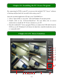
1
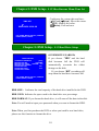
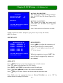
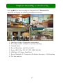
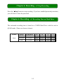
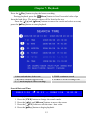
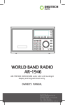
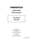
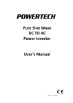
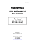
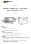
4 Channel Digital Video Recorder / Camera Kit Model No QV-3020 USER’S MANUAL 1 Important Note: Please keep this manual in a safe location in case you need to refer to it at a later date. 1 INDEX CHAPTER 1: DVR FEATURES................................................................................................................................. 1 CHAPTER 2: LAYOUT-2.1 FRONT PANEL ........................................................................................................... 1 CHAPTER 2: LAYOUT - 2.2 REAR PANEL ............................................................................................................ 2 CHAPTER 2: LAYOUT - 2.3 REMOTE CONTROL ............................................................................................... 2 CHAPTER 3: INSTALLATION - 3.1 HARD DRIVE INSTALLATION ................................................................ 3 CHAPTER 3: INSTALLATION - 3.2 CONNECTING CAMERA AND MONITOR ............................................ 3 CHAPTER 3: INSTALLATION - 3.3 CONNECTING POWER SUPPLY ............................................................. 3 CHAPTER 4: SYSTEM BOOTUP - 4.1 DETECTING INSTALLED HDD ........................................................... 3 CHAPTER 4: SYSTEM BOOTUP - 4.2 RECOVERING FILE SYSTEM ERRORS ............................................ 4 CHAPTER 4: SYSTEM BOOT - 4.3 RESTORE RECORDING FEATURE.......................................................... 4 CHAPTER 4: SYSTEM BOOT - 4.4 MAIN SCREEN ............................................................................................. 4 CHAPTER 5: DVR SETUP - 5.1 SETUP MENU ...................................................................................................... 5 CHAPTER 5: DVR SETUP - 5.2 CAMERA SELECT.............................................................................................. 6 CHAPTER 5: DVR SETUP - 5.3 RECORD SELECT .............................................................................................. 6 CHAPTER 5: DVR SETUP - 5.4 RESOLUTION...................................................................................................... 6 CHAPTER 5: DVR SETUP - 5.5 RECORD FRAME ............................................................................................... 7 CHAPTER 5: DVR SETUP - 5.6 RECORD QUALITY ........................................................................................... 7 CHAPTER 5: DVR SETUP - 5.7 SCHEDULE SET.................................................................................................. 8 CHAPTER 5: DVR SETUP - 5.8 MISCELLANEOUS MENU-AUTO RECORD ................................................. 8 CHAPTER 5: DVR SETUP - 5.9 MISCELLANEOUS MENU-PASSWORD ENABLE ....................................... 9 CHAPTER 5: DVR SETUP - 5.10 MISCELLANEOUS MENU-PASSWORD CHANGE .................................... 9 CHAPTER 5: DVR SETUP - 5.11 MISCELLANEOUS MENU-COLOR SET ...................................................... 9 CHAPTER 5: DVR SETUP - 5.12 MISCELLANEOUS MENU-TIME SET........................................................ 10 CHAPTER 5: DVR SETUP - 5.13 HARD DRIVE SETUP..................................................................................... 10 CHAPTER 5: DVR SETUP - 5.14 MOTION SET....................................................................................................11 CHAPTER 5: DVR SETUP - 5.15 VIDEO MODE.................................................................................................. 12 CHAPTER 5: DVR SETUP - 5.16 FACTORY RESET ........................................................................................... 12 CHAPTER 6: RECORDING - 6.1 START RECORDING ..................................................................................... 13 CHAPTER 6: RECORDING - 6.2 STOP RECORDING ........................................................................................ 14 CHAPTER 6: RECORDING - 6.3 RECORDING TIME ON HARD DRIVE ...................................................... 14 CHAPTER 7: PLAYBACK........................................................................................................................................ 15 CHAPTER 8.1: INSTALLING THE PC VIEWER PROGRAM ........................................................................... 16 CHAPTER 8.2: PC VIEWER INTERFACE............................................................................................................ 16 CHAPTER 8.3: PC BACKUP.................................................................................................................................... 17 CHAPTER 9.1: DVR SPECIFICATIONS................................................................................................................ 18 CHAPTER 9.2: CAMERA SPECIFICATIONS ...................................................................................................... 18 CHAPTER 10: APPENDIX -10.1 CONNECTION DIAGRAM............................................................................. 19 CHAPTER 10: APPENDIX - 10.2 DVR ACCESSORIES (INCLUDED).............................................................. 19 0 Chapter 1: DVR Features z z z z z z z Embedded Camera Power Supply. Simple Connection Method. Motion Detection. Scheduled / Motion Triggered Recording. PC Backup & Playback. Built in 320GB WD AV Surveillance Hard Drive. Remote Control. Chapter 2: Layout-2.1 Front Panel CH1 Select / Display Channel #1 CH2 Select / Display Channel #2 CH3 Select / Display Channel #3 CH4 Select / Display Channel #4 Quad Quad Display REW Rewind Pause Pause Play Play / List Recordings FWD Fast Forward Stop REC Stop Recording / Playback Record Menu/Esc Enter / Exit Menu SEL/Edit Select / Modify Item Up Move Up / Left Down Move Down / Right PWR Power Indicator HDD Hard Disk Drive Activity LED 1 Chapter 2: Layout - 2.2 Rear Panel Camera Inputs Video output Ground Terminal Power Supply Input Note: The USB port is located on the right hand side of the case. Chapter 2: Layout - 2.3 Remote Control CH1 Select / Display Channel #1 CH2 Select / Display Channel #2 CH3 Select / Display Channel #3 CH4 Select / Display Channel #4 Quad Quad Display Rewind Play / List Recordings Fast Forward Record Pause Stop Recording / Playback Enter / Exit Menu Menu Move Up / Left Select / Modify Item SEL Move Down / Right 2 Chapter 3: Installation - 3.1 Hard Drive Installation This unit has been factory fitted with a 320GB WD AV Surveillance Hard Disk; please return to the supplier for service or upgrades. Chapter 3: Installation - 3.2 Connecting Camera and Monitor There are 4 camera inputs and 1 video output (Refer to 2.2 Rear Panel). Chapter 3: Installation - 3.3 Connecting Power Supply (Refer to 2.2 Rear Panel). Please use only the power adapter supplied. Use of any other power source may void your warranty. Chapter 4: System Bootup - 4.1 Detecting Installed HDD After connecting power, the system will bootup and detect the installed hard drive. Checking HDD …… The on screen display will show the hard MASTER… drive information. Please note that the displayed capacity will be lower than the rated capacity due to space allocated to the file system. 3 Chapter 4: System Bootup - 4.2 Recovering File System Errors RECOVER HDD? 04811-101735 A power failure may cause errors in the file system. If errors are detected the DVR will (SELECT)YES/(MENU)NO give you the option to repair the errors. Chapter 4: System Boot - 4.3 Restore Recording Feature If a power failure occurs whilst the Power Error Detected system is recording the DVR will Restore Hard Disk (Master) OK automatically resume recording once Restore REC Mode………… OK power is restored. Note: If errors are detected these will need to be corrected first. (Refer to 4.2 Recovering File System Errors) Chapter 4: System Boot - 4.4 Main Screen While the DVR is operating the monitor will display the following information:Upper left: Percent of hard drive space used. Middle: Channel name (CH1 - CH4). Bottom right: Date and Time Bottom left: System status. (Refer to 6.1 Start Recording) 4 Chapter 5: DVR Setup - 5.1 Setup Menu Menu Directory CAMERA SELECT RECORD SELECT RESOLUTION MAIN MENU RECORD FRAME VIDEO QUALITY SCHEDULE SET AUTO RECORD MISCELLANEOUS MENU HARD DISK SET PASSWORD COLOR SET TIME SET MOTION SET VIDEO MODE FACTORY RESET MAIN MENU CAMERA SELECT RECORD SELECT RESOLUTION RECORD FRAME RECORD QUALITY SCHEDULE SET MISCELLANEOUS MENU HARD DISK SET MOTION SET VIDEO MODE FACTORY RESET 1234 1234 EACH 25 HIGH PAL [ Menu]: Enter menu. [ Up] and [ Down]: Move the cursor. [ SEL]: Select/Modify Settings. [ Menu]: Press again to exit. (UP, DOWN) MOVE (SELECT) CHANGE PRESS (MENU) TO EXIT 5 Chapter 5: DVR Setup - 5.2 Camera Select The DVR can display 4 cameras in the one screen (Quad Mode). Each channel can be enabled / disabled in case one or more camera inputs are not being used. Press [ SEL] to modify this setting, or press [CH1] - [CH4] to view each channel separately. If a channel is disabled, the system will display “OFF” on the monitor, this channel will not be displayed or recorded. Refer to 5.3 Record Select Chapter 5: DVR Setup - 5.3 Record Select This option allows you to select which channels will be recorded. Note: If no channels are selected an error message saying “record fault” and “no record channel” will appear briefly on the screen when the record button is pressed or scheduled / motion recording is started. Chapter 5: DVR Setup - 5.4 Resolution There are two modes of operation for recording resolution: 1. EACH MODE: The DVR compresses and records each video channel separately so you can enlarge a single channel to a full screen display whilst still recording on all channels. In this mode you can also record specific channels, for example, you could turn off recording on CH1 and CH2 and the system would only record video on CH3 and CH4. Press [CH1], [CH2], [CH3] or [CH4] to enlarge that channel to a full screen display. In EACH Mode you can also use the Auto Switch Function. 6 Auto Switch Function: When the system is in live view or recording mode, press and hold the [QUAD] button for three (3) seconds to enable the auto switch function. In auto switch mode each screen / channel will be displayed for three (3) seconds, including the “Quad” view. This process will continue until any button is pushed. For example, pressing [ Stop] will stop the auto switch function and may stop the unit recording. (depending on “Record Schedule” settings) (Refer to 5.7 Schedule Set). 2. QUAD MODE: The DVR will compress and record all 4 channels into one file; therefore, you cannot enlarge a single channel to full screen in play back mode or live monitoring mode. Note: The “Auto Switch” function is not available in QUAD MODE. Chapter 5: DVR Setup - 5.5 Record Frame Record frame(rate) will affect the appearance of moving objects in the recorded video. Higher framerates will show fast movement more clearly, however, they also use more hard disk space. The systems default value is 25fps (frames per second), which means the system will record 25 frames per second shared by all cameras. You can set the frame rate to 25, 12, 8, 6,4,3,2 or 1 frame per second. Chapter 5: DVR Setup - 5.6 Record Quality There are three levels of recording quality: High, Normal and Low. The higher you set the quality setting the more hard disk space will be used. 7 Chapter 5: DVR Setup - 5.7 Schedule Set In this option you can configure recording by Time or Motion Triggered Recording. SCHEDULE SET TTTMMMTTTTTTMMTTTTT--MMT │ │ │ │ │ │ │ │ │ 0 3 6 9 12 15 18 21 24 “-” No Recording. “T” Time (System Default). “M” Motion Detection Triggered. [ Up] and [ Down]: To move the cursor. (UP, DOWN) MOVE (SELECT) CHANGE PRESS (MENU) TO EXIT [ SEL]: To modify the recording method. The numbers along the bottom indicate the 24 hours of a day. For example: If you want to record using the motion triggered recording method from 3 to 6AM set the time points (3, 4, 5, 6) to “M”; if you want to continuously record from 7 to 12PM set the time points (19, 20, 21, 22, 23, 24) to “T”. Both of the recording methods need to be initiated by pressing the [ REC] button. After pressing the [ REC] button, if the schedule is set to “T” at that time the DVR will start to record immediately; if the schedule is set to “M” the DVR will start recording when motion is detected by the system. Forced Recording: When DVR is set to record using motion detection, the DVR will not record if the motion is lower than the threshold selected. If you want to record immediately press and hold the [ REC] button for 5 seconds and the DVR will start recording regardless of whether or not the level of motion is above the selected threshold. Chapter 5: DVR Setup - 5.8 Miscellaneous Menu-Auto Record When this function is set to “ON”, the DVR will return to scheduled recording five (5) minutes after the last user operation. This is useful if for example you forget to start recording again after stopping the unit to review the recorded footage. When you choose “OFF” the DVR will not start recording again until you press the [ REC] button. 8 Chapter 5: DVR Setup - 5.9 Miscellaneous Menu-Password Enable When this option is “ON”, you will be required to enter the password if you want to stop recording or enter the menu. System default password: Press [CH1] button six (6) times. Chapter 5: DVR Setup - 5.10 Miscellaneous Menu-Password Change CURRENT PASSWORD : ------ NEW PASSWORD : ------ CONFIRM PASSWORD : ------ All keys can be used for the password key except the [ Menu] key, which is used to exit. Note: If you forget your password refer to 5.16 Factory Reset. Chapter 5: DVR Setup - 5.11 Miscellaneous Menu-Color Set HUE: 0-99 SATURATION: 0-99. CONTRAST: 0-99. BRIGHTNESS: 0-99. [ Up] and [ Down]: Move the cursor. [REW]: Decrease the value. [FWD]: Increase the value. [CH1-CH4, QUAD]: Channel select. [ Menu]: Exit. 9 Chapter 5: DVR Setup - 5.12 Miscellaneous Menu-Time Set TIME SET ∨ 2008/08/08 20:08:08 Configures the system date and time: [ Up] and [ Down]: Move the cursor. [ SEL]: Modify the value. [ Menu]: Exit and save. (UP, DOWN) MOVE (SELECT) CHANGE PRESS (MENU) TO EXIT Chapter 5: DVR Setup - 5.13 Hard Drive Setup HARD DISK SET OVERWRITE ENABLED [YES] MASTER HDD SIZ 120042MB MASTER HDD USED 80865MB 77% MASTER HDD FORMAT SLAVE HDD SIZE N/A SLAVE HDD USED N/A SLAVE HDD FORMAT OVERWRITE ENABLED: If you choose “YES” and the hard disk becomes full the DVR will automatically overwrite the oldest footage on the disk. If you choose “NO” recording will stop when the hard drive becomes full. (UP, DOWN) MOVE (SELECT) CHANGE PRESS (MENU) TO EXIT HDD SIZE: Indicates the total capacity of the hard drive installed in the DVR. HDD USED: Indicates the space used in the hard drive as a percentage. HDD FORMAT: If you format the hard drive, it will erase all the data in the disk. Note: You will need to input your password when you want to format the HDD. Note: When you first purchase the DVR or when you install a new hard drive, please use this function to format the drive. 10 Chapter 5: DVR Setup - 5.14 Motion Set MOTION RECORD TIME: MOTION SET MOTION RECORD TIME: MOTION ALARM TIME: 10 OFF MOTION SET This adjusts how long recording continues after the DVR has last been triggered by motion. MOTION ALARM TIME: (UP, DOWN) MOVE (SELECT) CHANGE PRESS (MENU) TO EXIT This adjusts how long the buzzer will sound after the DVR has been triggered by motion. Note: Both values are shown in seconds. CONT: Continuous alarm. (Requires you press a key to stop the alarm) OFF: No alarm. MOTION SET: MOTION DETECTION SET >CHANNEL CHANNEL CHANNEL CHANNEL CHANNEL CHANNEL CHANNEL CHANNEL 1 SENSITIVITY 2 SENSITIVITY 3 SENSITIVITY 4 SENSITIVITY 1 2 3 4 AREA AREA AREA AREA 4 4 4 4 SET SET SET SET (UP, DOWN) MOVE (SELECT) CHANGE PRESS (MENU) TO EXIT SENSITIVITY: Press [ SEL] to adjust the sensitivity of the motion detection on each channel where “1” is the highest sensitivity and “9” is the lowest. When the sensitivity is set to “OFF”, the unit will not be triggered by motion on this channel. AREA SET: Press [ SEL] button to enter the detection area of each camera. Note: The image is divided into 16 (4*4) blocks. Press [REW] and [FWD] to move the cursor left and right. Press [ Up] and [ Down] to move the cursor up and down. Press [ SEL] to set add / remove the block from the detection area. Note: Make sure the appropriate times in Record Schedule are set to “M” for motion based recording to function. 11 Chapter 5: DVR Setup - 5.15 Video Mode This option enables you to select between PAL and NTSC video formats. This unit comes packaged with PAL format cameras for use in your region; as such you should not change this setting. Chapter 5: DVR Setup - 5.16 Factory Reset Press the [ SEL] button to restore the unit to default, the DVR will reboot and all settings (including the password) will be restored to the factory default settings. Caution: There is no confirmation dialog box after pressing the [ SEL] button! If you have forgotten your password: And the unit is not recording; keep the system on the main screen, and then press the [Pause] button ten (10) times in succession, the DVR will then reboot with default settings. Note: The default password is the [CH1] button six (6) times. If the DVR is recording, you will need to disconnect the HDD to force the machine to stop recording prior to resetting the machine to default. 12 Chapter 6: Recording - 6.1 Start Recording Press [ REC] to start recording (as configured in 5.7 Schedule Set). The DVR will display the following information on screen. 1. 2. 3. 4. 5. 6. 7. 8. Hard Drive Usage. (Displayed as a percentage) Recording Symbol. (Channel is currently recording) Channel Name. Record Resolution. (QUAD or EACH) Status. (REC, Play, FF1, FF2, FF3, REW, PAUSE) HDD Info. ([1] Master Hard Disk) Record Schedule: (T) Continuous (M) Motion Detection (-) No Recording The date and time. 13 Chapter 6: Recording - 6.2 Stop Recording Press the [ Stop] button to stop recording. If you have enabled password protection, you will need to enter the password. Chapter 6: Recording - 6.3 Recording Time on Hard Drive The estimated recording time is based on a 320GB Hard Drive with the unit in QUAD mode. (Times are shown in hours) System PAL Quality Frame Rate 25 12 6 1 HIGH 20 K Bytes 186 388 777 4662 NORMAL 15 K Bytes 249 518 1036 6216 LOW 12 K Bytes 311 647 1294 7764 14 Chapter 7: Playback Press the [ Play] button to play the latest recording. During playback, press the [ Menu] button to list all recorded video clips from the hard drive. The newest videos will be listed at the top. Press the [ Up] and [ Down] buttons to move the cursor and select an event, press the [ Play] button to start playback. 1. Start and end time of the event 3. MOTION: Motion triggered event 5. “*” marks unplayed video recordings 2. TIME: continuous record 4. FORCE: Forced recording event Search Date and Time ∨ 2008 /0 1 / 0 8 08 : 30 : 3 2 --- 2008/0 1 / 0 8 16 : 00 : 05 You can also playback recorded video by selecting an exact date and time as follows: 1. Press the [FWD] button to change the search mode. 2. Press the [ Up] and [ Down] buttons to move the cursor. 3. Press the [ SEL] button to edit the time / date value. 4. Press the [ Play] button to begin playback. 15 Chapter 8.1: Installing the PC Viewer Program By connecting the DVR to your PC you can use the included “PC Viewer” software to backup and play back the recorded video using your PC. Insert the included application CD into your CD-ROM Drive. 1. Select “Open folder to view files” from the Windows® autorun options. 2. Double click on the “PCViewerInstall.exe” file and follow the on screen instructions to install the PC Viewer software to your PC. 3. Run the installed PC Viewer program.When you connect the USB cable from the DVR to your PC Windows® will detect the hard drive installed inside the unit as a “removable disk”. Chapter 8.2: PC Viewer Interface 1 2 3 4 5 6 7 8 9 10 11 12 13 14 15 16 16 17 18 Item Remark 1. Capture picture Save an image of current frame 2. Save video clip 3. Directory Setting Save the current video clip to PC Change the capture directory on the PC 4. Time Search Search for recorded video by time 5. DVR event list Open the event list from DVR 6. DVR Mode* Switches between PC viewer mode and DVR 7. PC Mode* 8. Channel selection keys viewer mode CH1, CH2, CH3, CH4, QUAD 9. Playing scroll bar Quickly jump to a certain part of the video 10. Fast reverse Play backwards at fast speed 11. Previous frame Move to the previous frame 12. Reverse Play backwards at normal speed 13. Pause Pause playing 14. Play Play forwards at normal speed 15. Next frame Move to the next frame 16. Fast forward Play forwards at fast speed 17. Volume scroll bar Not relevant to this model 18. Exit Exit the PC Viewer DVR Mode: Plays video clips saved on the DVR’s HDD. PC Mode: Plays video clips (.mys file) saved on the PCs hard drive Chapter 8.3: PC Backup 8.3 PC Backup Press the button to open the DVR’s event list, then select an event and press to start the backup procedure. The video file you want to save on PC can be saved as an “.avi” file or “.mys” file. 17 Chapter 9.1: DVR Specifications ITEM DESCRIPTION NOTE Operating System Camera Inputs Custom Vineyard ASIC 4 4p mini-din socket Video Outputs 1 BNC socket Display Frame Rate Recording Frame Rate (Quad) 100 frames/second Max.25 fps 4 × 25 fps Recording Frame Rate (Each) 25 fps ÷ Number of Cameras Max. 25 fps (Global) Record Mode Continuous, Time Schedule, Motion Triggered. Display 720 × 576 Record 320 × 136 (QUAD) 640 × 272 (EACH) Resolution Video Compression Format (Each Channel) HDD Estimated Record Length USB Remote Control Method Full Screen Dimension ( L × W × H ) Search QUAD: 640 × 272 Low : 12K Byte Normal: 15K Byte High : 20K Byte 320GB SATA Interface 320GB Hard drive @ 6 frames per second & Normal Quality = 1036Hours For PC playback & backup USB 2.0 Included Time、Date、Event YES 250 × 235 × 38mm Modified Motion-JPEG (12-20K bytes/frame) Chapter 9.2: Camera Specifications Image Sensor: 1/4” Color CMOS Resolution: 350 TVL Minimum Illumination: 1.5Lux/F2.0 (IR off) Lens: 3.6/6.0mm Power Requirements: DC 12V 50mA Dimensions: 46(Ø) x 107(L)mm Operating Temperature: -20°C - +50°C Video Output: 1.0Vp-p 75Ω S/N ratio: >48Db 18 Chapter 10: Appendix -10.1 Connection Diagram Chapter 10: Appendix - 10.2 DVR Accessories (included) Power Cord Note: The plug will vary depending on Remote Controller Power Adaptor User’s Manual target market. 15M Video and Power cable X 2 2 x IR Cameras 19 USB Cable CD-ROM 20 Distributed by: Electus Distribution Pty Ltd 320 Victoria Rd Rydalmere NSW 2116 Australia www.electusdistribution.com.au 6