1
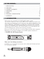
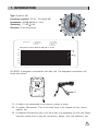
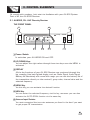
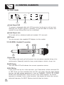
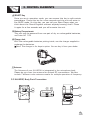
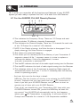
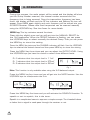
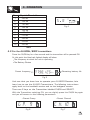
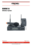
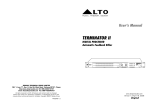
R
LTO
OWNER'S MANUAL
AU-800R/800H/800P SERIES
WIRELESS MICROPHONE SYSTEM
LTO
R
HM-38
www.altoproaudio.com
Version 2.0 OCT. 2007
English
IMPORTANT SAFETY INSTRUCTION
CAUTION
RISK OF ELECTRIC SHOCK
DO NOT OPEN
TO REDUCE THE RISK OF ELECTRIC SHOCK
PLEASE DO NOT REMOVE THE COVER OR
THE BACK PANEL OF THIS EQUIPMENT.
THERE ARE NO PARTS NEEDED BY USER
INSIDE THE EQUIPMENT. FOR SERVICE,
PLEASE CONTACT QUALIFIED SERVICE
CENTERS.
WARNING
To reduce the risk of electric shock
and fire, do not expose this equipment
to moisture or rain.
Dispose of this product should
not be placed in municipal waste
and should be separate collection.
11. Move this Equipment only with a cart,
stand, tripod, or bracket,
This symbol, wherever used, alerts you to the
specified by the
presence of un-insulated and dangerous voltages
manufacturer, or
within the product enclosure. These are voltages that
sold with the
may be sufficient to constitute the risk of electric
Equipment. When
shock or death.
a cart is used, use
This symbol, wherever used, alerts you to
caution when
important operating and maintenance instructions.
moving the cart /
Please read.
equipment
Protective Ground Terminal
combination to
AC mains (Alternating Current)
avoid possible
Hazardous Live Terminal
injury from tip-over.
ON: Denotes the product is turned on.
12. Permanent hearing loss may be caused by
OFF: Denotes the product is turned off.
exposure to \ extremely high noise levels.
CAUTION
The US. Government's Occupational Safety
Describes precautions that should be observed to
and Health Administration (OSHA) has
prevent damage to the product.
specified the permissible exposure to noise
1. Read this Manual carefully before operation.
level.
2. Keep this Manual in a safe place.
These are shown in the following chart:
3. Be aware of all warnings reported
with this symbol.
HOURS X DAY SPL EXAMPLE
4. Keep this Equipment away from water and
90 Small gig
8
moisture.
92 train
6
5. Clean it only with dry cloth. Do not use
95 Subway train
4
solvent or other chemicals.
97 High level desktop monitors
3
6. Do not damp or cover any cooling opening.
100 Classic music concert
2
Install the equipment only in accordance with
102
1,5
the Manufacturer's instructions.
105
1
7. Power Cords are designed for your safety. Do
110
0,5
not remove Ground connections! If the plug
0,25 or less 115 Rock concert
does not fit your AC outlet, seek advice from
a qualified electrician. Protect the power
According to OSHA, an exposure to high SPL in
cord and plug from any physical stress to
excess of these limits may result in the loss of
avoid risk of electric shock. Do not place
heat. To avoid the potential damage of heat, it is
heavy objects on the power cord. This could
cause electric shock or fire.
recommended that Personnel exposed to
equipment capable of generating high SPL use
8. Unplug this equipment when unused for long
hearing protection while such equipment is
periods of time or during a storm.
under operation.
9. Refer all service to qualified service personnel
The apparatus shall be connected to a mains
only. Do not perform any servicing other than
those instructions contained within the
socket outlet with a protective earthing
User's Manual.
connection.
10. To prevent fire and damage to the product,
use only the recommended fuse type as
indicated in this manual. Do not short-circuit
the fuse holder. Before replacing the fuse,
make sure that the product is OFF and
disconnected from the AC outlet.
The mains plug or an appliance coupler is used
as the disconnect device, the disconnect device
shall remain readily operable.
IN THIS MANUAL:
1. INTRODUCTION...............................................................................1
2. FEATURES......................................................................................3
3. CONTROL ELEMENTS.....................................................................4
4. OPERATION ...................................................................................8
5. ANNEX ..........................................................................................13
6. TECHNICAL SPECIFICATIONS..........................................................18
7. WARRANTY..................................................................................19
1. INTRODUCTION
Thank you for your purchasing the AU-800 LTO wireless system.
Your AU-800 is based on a new revolutionary UHF PLL (phase loop locked) circuit
which allows the simultaneous use of more than 144 channels (depending on your
country regulations). The Receiver is provided with 2 antennas that constantly
monitor the incoming RF (radio frequency) signal and send only the stronger RF
signal to the AU-800 Receiver. Your AU-800 system is full of key features such
as AUTO-SCAN function, battery level monitoring and others.
Enjoy your AU-800 and make sure to read this Manual carefully before operation!
Depending on the options available your AU-800 system consists of:
1. AU-800R, PLL UHF Diversity Receiver
R
LTO
ANT B
GROUP
CHANNEL
AF
RF
UP
MENU
DOWN
MEM
AU-800R
MHz
PLL UHF DIVERSITY WIRELESS RECEIVER
ANT-A
POWER
ANT-B
Either one of the following transmitters:
AU-800H: It is a handheld transmitter with rubberised finished and level
hi-fi microphone capsule.
R
MHz
LTO
AU-800H
1
1. INTRODUCTION
Type: Dynamic Mic.
Frequency response: 50 Hz~16 kHz( 3 dB)
Impedance: 300
20% at 1kHz
Sensitivity: -71 dB 3 dB
Direction: Omni-directional
Y:-50.9 dBv/Pa
Y:-48.6 dBm/Pa
D:0.0 dB
X:1000 Hz
Y:-77.5 dBv/Pa
Y:-75.3 dBm/Pa
D:0.0 dB
D:-26.6 dB
Microphone Frequency Response Magn dB re 1V/uBr
-40
0
-50
180
-60
-70
-80
-90
20
50
100
200
500
1K
2K
5K
10K
20K
AU-800P: A bodypack transmitter with belt clip. The bodypack transmitter will
come with either:
MHz
SELECT
CH/ON
R
LTO
(1)
AU-800P
(1). A cable to be connected to an electric guitar or bass.
(2). A Lavalier Microphone. This is the little "bug" to be clipped on ties, shirts,
nipples, etc.
(3). A Headset Microphone that is fit like a pair of sunglasses so that the Player
has both hands free to play an instrument, dance, shot the Audience, etc.
2
1. INTRODUCTION
(2)
LM-10, Clip microphone
Preset Impedance: 680 ohm
Freq. Response: 50-12 kHz;
Sensitivity: -65 dB 3 dB at 1kHz
Directional: 12 180 mm( 0.47" 7.1")
Weight: 22g(0.049Ib)
(3)
HM-38, Condenser microphone
Preset Impedance: 600 ohm
Freq. Response: 80-12 kHz;
Sensitivity: -68 dB+/-3 dB at 1kHz;
Directional: Uni-directional;
Weight: 52g (0.12Ib)
2. FEATURES
- FEATURES OF AU-800R, PLL UHF DIVERSITY RECEIVER
User Friendly interface including a large blue back lighted display and an
intuitive MENU system for easy operation.
Auto Scan Function
2 Antennas and switching diversity circuit
Selector for three different audio output levels depending of kind of mixer used
Squelch control to minimize RF interferences
- FEATURES OF AU-800H AND AU-800P TRANSMITTERS
Soft touch rubberised painting to avoid handling noise
Rechargeable battery design
Selector for three different output levels depending of kind of receiver used
LCD display
Battery status display
Mute function (this function is very welcomed by Politicians...)
Lock function to avoid miss action during a live performance
Each AU-800 System complies with EMC regulations and includes 144 different channels.
(Not all channels may be available in certain Countries depending on local regulations).
They are manufactured under ISO9000:2000, ISO/TS 16949:2002 quality
management system.
3
SP
OT
L
IG
3. CONTROL ELEMENTS
HT
Ok, enough with numbers. Let's start to familiarize with your AU-800 System.
First of all, the AU-800R Receiver:
3.1 AU-800R, PLL UHF Diversity Receiver
THE FRONT PANEL
6
6
4
R
LTO
ANT B
GROUP
AF
RF
UP
MENU
DOWN
MEM
AU-800R
MHz
CHANNEL
PLL UHF DIVERSITY WIRELESS RECEIVER
ANT-A
POWER
3
2
5
ANT-B
1
1 Power Switch
It switches your AU-800R ON and OFF.
2 UP/DOWN Keys
You can adjust the right values through these two keys once the MENU is
activated.
3 DISPLAY
All the key functions of your AU-800 Receiver are monitored through this
big, amazing, blue back lighted display such as: Radio Signal, Audio Signal,
Battery life (absolutely with some little magic you can see the battery life of
the transmitter directly on the receiver!), group value, channel value and the
selected frequency.
4 MENU Key
Via this key you can activate the desired function.
5 MEM Key
You can enter the selected frequency via this key, moreover you can also
activate the AUTO-SCAN function via the same key.
6 Antenna Input Sockets
You must connected the two cute antennas you found in the box if you want
to get proper RF transmission.
4
SP
OT
L
IG
3. CONTROL ELEMENTS
HT
THE REAR PANEL
15-18V DC
500mA
AF OUT
UNBALANCED
AF OUT
BALANCED
1
2
3
1 Audio Output XLR
To connect a balanced cable with XLR connector (we forgot to tell you that
although your AU-800 system is wireless, you will still need to connect the
receiver to your Mixing Desk and to a wall plug!)
2 Audio Output Jack
To be used with an unbalanced cable and standard 1/4" mono jack.
3 DC Input
You can connect the supplied AC Adapter to this socket.
3.2 AU-800H, Handheld Transmitter
6
5
4 2
1
R
MHz
LTO
AU-800H
7
3
1 Front Grill
This spring steel mesh grill will protect the microphone capsule during a live
performance. Especially made for heavy metal players, alcohol, drugs, etc.
2 LCD Display
This nice blue LCD will indicate the current operation status.
3 CH/ON Key
If you press this key for a few seconds, your Transmitter will be switched ON
or OFF. Once you have switched the unit ON, just press this key again slightly
and you can edit various parameters, such as CHANNEL, GROUP, RF POWER
LEVEL and LOCK/UNLOCK. Once you are in the LOCK position, no further
operation is allowed. And in a few seconds, the display will show the current
selected frequency (In MHZ). Battery level will also be shown.
5
SP
OT
L
IG
3. CONTROL ELEMENTS
HT
4 SELECT Key
Once you are in operation mode, you can access this key to edit certain
parameters. Press this key for a few seconds and the unit will enter in
the MUTE mode. (In this way, you can tell your Bass Player what you
think about the Sound Engineer without anybody knowing that!). Press
it again for a few seconds and you will unmute the unit.
5 Battery Compartment
This unit may be powered from one pair of dry or rechargeable batteries,
um3 size AA 1.5V.
6 Charge Jack
With the rechargeable batteries putting inside, use the charger supplied to
recharge the batteries.
Note: This charger is for buyer's option. You can buy it from your dealer.
7 Antenna
The Antenna of your AU-800H is integrated in the microphone body.
Please do not cover the antenna for optimal RF transmission. We also
include 7 different color antenna covers for multiple operation of frequency.
3.3 AU-800P, Body Pack Transmitter
1
2
MHz
3
SELECT
CH/ON
R
LTO
4
7
5
+
-
-
+
6
AU-800P
8
6
SP
OT
L
IG
3. CONTROL ELEMENTS
HT
1 LCD Display
This nice blue LCD will indicate the current operation status.
2 CH/ON Key
If you press this key for a few seconds, your Transmitter will be switched
ON or OFF. Once you have switched the unit ON, just press this key again
slightly and you can edit various parameters such as CHANNEL, GROUP,
RF POWER LEVEL and LOCK/UNLOCK. Once you are in the LOCK position
no further operation is allowed. And in a few seconds, the display will show
the current selected frequency (in MHZ). Battery level will also be shown.
3 SELECT Key
Once you are in operation mode, you can access this key to edit certain
parameters. Press this key for a few seconds and the unit will enter in the
MUTE mode. (In this way, you can tell your Bass Player what you think about
the Sound Engineer without everybody knowing that!). Press it again for a few
seconds and you will unmute the unit.
4 Mini 4P Connector
This connector is used to connect the unit with the clip microphones. for
example, HM-38 condenser microphone or LM-10 clip microphone.
(1) (4) (3)
(2)
Pin 1, GND
Pin 2, Phantom power supply for Condenser microphone
Pin 3, for Guitar, bass and keyboards
Pin 4, for Dynamic or Condenser microphone
5 Charge Jack
With the rechargeable batteries put inside, use the charger supplied to
recharge the batteries.
6 Battery Compartment
This unit may be powered from one pair dry or rechargeable batteries,
Um3 size AA 1.5V.
7 Belt Clip
It is the detachable belt clip for easy carry during the live applications.
8 Antenna
It is a flexible antenna. To get effective transmission, never cover the
antenna with hand, clothes, etc. during operation, and always position
the transmitter nearby the receiver.
7
4.
OPERATION
3. CONTROL
ELEMENTS
OK, if so far you remember all the functions and features of your AU-800
system you are ready to operate the Unit. Let's start from the Receiver:
4.1 For the AU-800R, PLL UHF Diversity Receiver
A
H
F
B C
G E
D
A.This indicates the Frequency Group. There are 12 Groups and each
Group includes 12 different channels (frequencies).
B.This indicates the Channel Number. There are 12 channels for each one
of the 12 Groups for a total of 144 channels.
C.MUTE: If the Display shows , the Mute function is disengaged. If the
display shows , the Mute function is engaged.
D.This shows the selected frequency.
E.This shows you the remaining life of the Battery of your Transmitter. 3
segments means full life, 1 segment means it is time to replace or
recharge the battery. If this icon disappeared, it means
that your transmitter is switched OFF.
F. This bar(AF) indicates the level of the audio signal coming into the Receiver.
G.This bar(RF) indicates the level of radio signal coming into the Receiver.
H.This indicates which of the 2 antennas is operating. Radio signal will
automatically switch from Ant 1 to Ant 2, indicating that the diversity
circuit is operating properly.
- And now, let's see the four keys in detail:
MEM key: The first function of this key is to activate the AUTO-SCAN
function. Suppose that you have more than one LTO transmitter in
front of you with your AU-800R Receiver and you want to start to
operate one of them with your AU-800 Receiver.
First of all, you should turn your Transmitter ON, then with your
AU-800R Receiver turned ON, press the MEM key at least for
one second. Your AU-800R will automatically look for the frequency
where your LTO Transmitter is operating. It will scan all the 12
Groups and Channels for a total of 144 frequencies available.
8
4.
OPERATION
3. CONTROL
ELEMENTS
During this process, the audio output will be muted and the display will show
you the Group Number scanned, the channel number scanned and the
frequency that is being scanned. Once the transmitter frequency has been
found, the display will flash and the RF bar indicator and Battery life icon will
appear. Press MEM again slightly and such frequency will be stored into your
AU-800R Receiver. Please note that frequencies can be scanned manually
using the UP/DOWN key. See the Annex for more details.
MENU key: This key activates several functions:
Press this key slightly once and you will get into the MANUAL SELECT for
the 144 frequencies. When the GROUP indicator is flashing, you can press
the UP/DOWN keys to select manually the desired Group. Then you can press
the MEM key to store this setting.
Press the MENU key twice and the CHANNEL indicator will flash. Use the UP/DOWN
keys to selected the desired channel and then press MEM key to store this setting.
Press the MENU key three times and you can adjust the OUTPUT LEVEL. Using
the UP/DOWN keys you have the choice to select three different levels:
PL 0 indicates that the output level is 1.1mV
PL 1 indicates that the output level is 575mV
PL 2 indicates that the output level is 250mV
AF
RF
MHz
Fig 1
Note: This function is only available when using the XLR balanced output.
Press the MENU key four times and you will get into the MUTE function. Use the
UP/DOWN keys to mute/unmute the Unit.
AF
RF
AF
RF
MHz
Fig 2 mute function off
MHz
Fig 3 mute function on
Press the MENU key five times and you will activate the SQUELCH function. To
squelch or not to squelch, this is the issue...
Squelch is a complicated name to express a simple concept: The threshold above
or below that a signal is made pass through the receiver or not.
9
4.
OPERATION
3. CONTROL
ELEMENTS
No.
1
Squelch Threshold
-99 dB
2
3
-96 dB
4
-86 dB
5
6
-82 dB
-77 dB
7
-72 dB
8
9
-68 dB
-64 dB
10
-62 dB
AF
RF
MHz
-90 dB
Fig 4
Table
4.2 For the AU-800H/800P transmitters
Press the CH/ON key for a few seconds and the transmitter will be powered ON.
At this point the blue back lighted display will show:
The frequency at which the unit is operating
The Battery Status
Preset frequency
MHz
Remaining battery life
Fig 5
And now that you know how to operate your AU-800R Receiver, let's
learn how to use the AU-800 Transmitters. The following instructions
apply both to the handheld version and to the bodypack version.
There are 2 keys on the Transmitter labelled CH/ON and SELECT.
With the Transmitter switching ON, you can slightly press the CH/ON key again
and you will access to the following parameters:
Preset Group
Fig 6
Preset Channel
Fig 7
10
4.
OPERATION
3. CONTROL
ELEMENTS
Note: Why LTO wireless systems come with 144 different frequencies?
Not because you will need to use 144 different microphones at the same
time. It is unlikely that you will use more than 8 systems at the same
time so why 144 frequencies? This mainly depends on Countries regulations.
We offer frequencies from 470 to 900 MHZ. Some of these frequencies
are illegal in certain Countries and vice versa. Offering such a wide range of
frequencies we make sure that each single Country on the planet will
have more than enough choice of frequencies available. Not only: A
certain frequency is close to the frequency generated by lighting equipment,
a computer, a fax machine and so on. Therefore, thanks to the large
number of frequencies available you can easily switch to another frequency
that is interference-free.
In your Transmitter, there are 12 frequency bands or GROUPS. Each Group
contains 12 channels according to EMC regulations.
To select a Group you must first switch your Transmitter ON by pressing the
CH/ON key for a few seconds until you hear the beep and the blue display is
lighted. Then press the CH/ON key again slightly and you will access the GROUP
menu. At this point use the SELECT key to change the GROUP value from 1 to
12. Now, to access the CHANNEL menu, press again slightly the CH/ON key
two times and use the SELECT key to change frequency from 1 to 12. Your
setting will be automatically saved in a few seconds and the display will go back
to the main menu showing the operating frequency.
Note: Once you have changed the operating frequency on your Transmitter,
you need to activate the SCAN function in your AU-800R Receiver. In this way,
the Receiver with synchronize automatically on the Transmitter frequency.
- RF Output Power Select
Your Transmitter can operate on three different levels of output power. These
are different from the Handheld Model and the Bodypack model.
For the Handheld model the
- PL 0, the output power is
- PL 1, the output power is
- PL 2, the output power is
levels are
5 dBm
10 dBm
15 dBm
And for the Bodypack version the levels are
- PL 0, the output power is 3 dBm
- PL 1, the output power is 5 dBm
- PL 2, the output power is 12 dBm
position the transmitter nearby the receiver.
11
4.
OPERATION
3. CONTROL
ELEMENTS
- LOCK Function
You don't want accidental change of frequency or other setting in the middle of a
performance, do you? Any miss-operation during a live performance can be easily
avoided thanks to the LOCK function. With the LOCK function ON no further change
of setting is allowed until the Transmitter is unlocked. To access the LOCK Menu,
press the CH/ON key four times and then press the SELECT key to lock or unlock
the Transmitter Settings. Your choice of setting will automatically be saved into the
Transmitter in a few seconds. The blue display shows "lock" and "unlock" depending
on the operating mode.
Fig 10: LOCK
Fig 11: UNLOCK
- Mute Function
Sometimes, there are things that you want to tell to your Friends on stage or
your nearby Companion during a Meeting but not necessarily to the rest of the
world especially if you are ON LIVE on CNN... A smart feature on your Transmitter
allows you to easily MUTE the microphone so you are free to talk to the people
next to you without the rest of the world hearing what you say. To enter into
MUTE function simply press the SELECT key for a few seconds and the Transmitter
will mute any audio signal going to the Receiver. Press SELECT again for a few
seconds and you will UNMUTE the Transmitter.
12
5. ANNEX
Frequency Band Selection
Most countries closely regulate the radio frequencies used in the transmission
of wireless information. These regulations state which devices can use which
frequencies, and help to limit the amount of RF(radio frequency)interference in all
wireless communications. To be flexible enough to operate worldwide, MOD-800R
Wireless receivers are available in a number of models, each with a unique
frequency range. Each frequency range, or band, spans up to 24 MHz of the
wireless broadcast spectrum. Available bands are:
F1:470.000-494.000(470-496)MHz
F2:518.000-542.000(518-544)MHz
F3:572.000-596.000(572-598)MHz
F4:638.000-662.000(638-664)MHz
F5:702.000-726.000(702-731)MHz
F6:740.000-764.000(740-769)MHz
F7:798.000-822.000(798-827)MHz
F8:850.000-874.000(850-879)MHz
F9:915.000-939.000(915-944)MHz
F1: 470.000-494.000(470-496)MHz
Group1
Group2
Group3
Group4
Group5
1
470.125
470.325
470.525
470.725
470.925
Group6
471.125
2
471.325
471.525
471.725
471.925
472.125
472.325
3
472.525
472.725
472.925
473.125
473.325
473.525
4
473.725
473.925
474.125
474.325
474.525
474.725
5
6
474.925
476.125
475.125
476.325
475.325
476.525
475.525
476.725
475.725
476.925
475.925
477.125
7
477.325
477.525
477.725
477.925
478.125
478.325
8
478.525
478.725
478.925
479.125
479.325
479.525
9
10
479.725
480.925
479.925
481.125
480.125
481.325
480.325
481.525
480.525
481.725
480.725
481.925
11
482.125
482.325
482.525
482.725
482.925
483.125
12
483.325
483.525
483.725
483.925
484.125
484.325
F2: 518.000-542.000(518-544)MHz
13
Group1
Group2
Group3
Group4
Group5
1
518.125
518.325
518.525
518.725
518.925
Group6
519.125
2
519.325
519.525
519.725
519.925
520.125
520.325
3
520.525
520.725
520.925
521.125
521.325
521.525
4
5
521.725
522.925
521.925
523.125
522.125
523.325
522.325
523.525
522.525
523.725
522.725
523.925
6
524.125
524.325
524.525
524.725
524.925
525.125
7
525.325
525.525
525.725
525.925
526.125
526.325
8
9
526.525
527.725
526.725
527.925
526.925
528.125
527.125
528.325
527.325
528.525
527.525
528.725
10
528.925
529.125
529.325
529.525
529.725
529.925
11
530.125
530.325
530.525
530.725
530.925
531.125
12
531.325
531.525
531.725
531.925
532.125
532.325
5. ANNEX
F3: 572.000-596.000(572-598)MHz
1
Group1
572.125
Group2
572.325
Group3
572.525
Group4
572.725
Group5
572.925
Group6
573.125
2
3
573.325
574.525
573.525
574.725
573.725
574.925
573.925
575.125
574.125
575.325
574.325
575.525
4
575.725
575.925
576.125
576.325
576.525
576.725
5
576.925
577.125
577.325
577.525
577.725
577.925
6
578.125
578.325
578.525
578.725
578.925
579.125
7
579.325
579.525
579.725
579.925
580.125
580.325
8
580.525
580.725
580.925
581.125
581.325
581.525
9
581.725
581.925
582.125
582.325
582.525
582.725
10
11
582.925
584.125
583.125
584.325
583.325
584.525
583.525
584.725
583.725
584.925
583.925
585.125
12
585.325
585.525
585.725
585.925
586.125
586.325
F4: 638.000-662.000(638-664)MHz
Group1
Group2
Group3
Group4
Group5
1
638.125
638.325
638.525
638.725
638.925
Group6
639.125
2
639.325
639.525
639.725
639.925
640.125
640.325
3
640.525
640.725
640.925
641.125
641.325
641.525
4
641.725
641.925
642.125
642.325
642.525
642.725
5
642.925
643.125
643.325
643.525
643.725
643.925
6
644.125
644.325
644.525
644.725
644.925
645.125
7
645.325
645.525
645.725
645.925
646.125
646.325
8
646.525
646.725
646.925
647.125
647.325
647.525
9
10
647.725
648.925
647.925
649.125
648.125
649.325
648.325
649.525
648.525
649.725
648.725
649.925
11
650.125
650.325
650.525
650.725
650.925
651.125
12
651.325
651.525
651.725
651.925
652.125
652.325
14
5. ANNEX
F5: 702.000-726.000(702-731)MHz
Group1
Group2
Group3
Group4
Group5
Group6
Group7
Group8
Group9
Group10 Group11 Group12
1 702.125 702.325 702.525 702.725 702.925 703.125 703.325 703.525 703.725 703.925 704.125 704.325
2 704.525 704.725 704.925 705.125 705.325 705.525 705.725 705.925 706.125 706.325 706.525 706.725
3 706.925 707.125 707.325 707.525 707.725 707.925 708.125 708.325 708.525 708.725 708.925 709.125
4 709.325 709.525 709.725 709.925 710.125 710.325 710.525 710.725 710.925 711.125 711.325 711.525
5 711.725 711.925 712.125 712.325 712.525 712.725 712.925 713.125 713.325 713.525 713.725 713.925
6 714.125 714.325 714.525 714.725 714.925 715.125 715.325 715.525 715.725 715.925 716.125 716.325
7 716.525 716.725 716.925 717.125 717.325 717.525 717.725 717.925 718.125 718.325 718.525 718.725
8 718.925 719.125 719.325 719.525 719.725 719.925 720.125 720.325 720.525 720.725 720.925 721.125
9 721.325 721.525 721.725 721.925 722.125 722.325 722.525 722.725 722.925 723.125 723.325 723.525
10 723.725 723.925 724.125 724.325 724.525 724.725 724.925 725.125 725.325 725.525 725.725 725.925
11 726.125 726.325 726.525 726.725 726.925 727.125 727.325 727.525 727.725 727.925 728.125 728.325
12 728.525 728.725 728.925 729.125 729.325 729.525 729.725 729.925 730.125 730.325 730.525 730.725
F6: 740.000-764.000(740-769)MHz
Group1 Group2 Group3
Group4 Group5 Group6 Group7 Group8 Group9 Group10 Group11 Group12
1
740.125 740.325 740.525 740.725 740.925 741.125 741.325 741.525 741.725 741.925 742.125 742.325
2
742.525 742.725 742.925 743.125 743.325 743.525 743.725 743.925 744.125 744.325 744.525 744.725
3
744.925 745.125 745.325 745.525 745.725 745.925 746.125 746.325 746.525 746.725 746.925 747.125
4
747.325 747.525 747.725 747.925 748.125 748.325 748.525 748.725 748.925 749.125 749.325 749.525
5
749.725 749.925 750.125 750.325 750.525 750.725 750.925 751.125 751.325 751.525 751.725 751.925
6
752.125 752.325 752.525 752.725 752.925 753.125 753.325 753.525 753.725 753.925 754.125 754.325
7
754.525 754.725 754.925 755.125 755.325 755.525 755.725 755.925 756.125 756.325 756.525 756.725
8
756.925 757.125 757.325 757.525 757.725 757.925 758.125 758.325 758.525 758.725 758.925 759.125
9
759.325 759.525 759.725 759.925 760.125 760.325 760.525 760.725 760.925 761.125 761.325 761.525
10 761.725 761.925 762.125 762.325 762.525 762.725 762.925 763.125 763.325 763.525 763.725 763.925
11 764.125 764.325 764.525 764.725 764.925 765.125 765.325 765.525 765.725 765.925 766.125 766.325
12 766.525 766.725 766.925 767.125 767.325 767.525 767.725 767.925 768.125 768.325 768.525 768.725
15
5. ANNEX
F7: 798.000-822.000(798-827)MHz
Group1
Group2 Group3 Group4
Group5
Group6
Group7
Group8
Group9
Group10 Group11 Group12
1
798.125 798.325 798.525 798.725
798.925 799.125 799.325 799.525 799.725 799.925
800.125 800.325
2
800.525 800.725 800.925 801.125
801.325 801.525 801.725 801.925 802.125 802.325
802.525 802.725
3
802.925 803.125 803.325 803.525
803.725 803.925 804.125 804.325 804.525 804.725
804.925 805.125
4
805.325 805.525 805.725 805.925
806.125 806.325 806.525 806.725 806.925 807.125
807.325 807.525
5
807.725 807.925 808.125 808.325
808.525 808.725 808.925 809.125 809.325 809.525
809.725 809.925
6
810.125 810.325 810.525 810.725
810.925 811.125 811.325 811.525 811.725 811.925
812.125 812.325
7
812.525 812.725 812.925 813.125
813.325 813.525 813.725 813.925 814.125 814.325
814.525 814.725
8
814.925 815.125 815.325 815.525
815.725 815.925 816.125 816.325 816.525 816.725
816.925 817.125
9
817.325 817.525 817.725 817.925
818.125 818.325 818.525 818.725 818.925 819.125
819.325 819.525
10 819.725 819.925 820.125 820.325
820.525 820.725 820.925 821.125 821.325 821.525
821.725 821.925
11 822.125 822.325 822.525 822.725
822.925 823.125 823.325 823.525 823.725 823.925
824.125 824.325
12 824.525 824.725 824.925 825.125
825.325 825.525 825.725 825.925 826.125 826.325
826.525 826.725
Remark:
1. The values with underlines should be scanned manually by adjusting the UP/DOWN key.
2. The following channels can be used simultaneously without any interference.
Group 1-1: 798.125
Group 1-10: 819.725
Group 2-2: 800.725
Group 2-5: 807.925
Group 3-4: 805.725
Group 2-6: 810.325
Group 5-8: 815.725
Group 4-11: 822.725
Group 8-6: 811.525
Group 8-8: 816.325
16
5. ANNEX
F8: 850.000-874.000(850-879)MHz
Group10
Group11 Group12
1
850.125 850.325
Group1
Group2
850.525 850.725
Group3
Group4
850.925 851.125 851.325 851.525 851.725 851.925
Group5
Group6
Group7
Group8
Group9
852.125 852.325
2
852.525 852.725
852.925 853.125
853.325 853.525 853.725 853.925 854.125 854.325
854.525 854.725
3
854.925 855.125
855.325 855.525
855.725 855.925 856.125 856.325 856.525 856.725
856.925 857.125
4
857.325 857.525
857.725 857.925
858.125 858.325 858.525 858.725 858.925 859.125
859.325 859.525
5
859.725 859.925
860.125 860.325
860.525 860.725 860.925 861.125 861.325 861.525
861.725 861.925
6
862.125 862.325
862.525 862.725
862.925 863.125 863.325 863.525 863.725 863.925
864.125 864.325
7
864.525 864.725
864.925 865.125
865.325 865.525 865.725 865.925 866.125 866.325
866.525 866.725
8
866.925 867.125
867.325 867.525
867.725 867.925 868.125 868.325 868.525 868.725
868.925 869.125
9
869.325 869.525
869.725 869.925
870.125 870.325 870.525 870.725 870.925 871.125
871.325 871.525
10 871.725 871.925
872.125 872.325
872.525 872.725 872.925 873.125 873.325 873.525
873.725 873.925
11 874.125 874.325
874.525 874.725
874.925 875.125 875.325 875.525 875.725 875.925
876.125 876.325
12 876.525 876.725
876.925 877.125
877.325 877.525 877.725 877.925 878.125 878.325
878.525 878.725
Remark:
1. The values with underlines should be scanned manually by adjusting the UP/DOWN key.
2. The following channels can be used simultaneously without any interference.
Group 1-1: 850.125
Group 1-10: 851.925
Group 2-2: 852.725
Group 2-5: 859.925
Group 3-4: 857.725
Group 2-6: 862.325
Group 5-8: 867.725
Group 4-11: 874.725
Group 8-6: 863.525
Group 8-8: 868.325
F9: 915.000-939.000(915-944)MHz
Group1
1
Group2
Group3
Group4
Group5
Group6
Group7
Group8
Group9
Group10 Group11
Group12
915.125 915.325 915.525 915.725 915.925 916.125 916.325 916.525 916.725 916.925 917.125 917.325
2
917.525 917.725 917.925 918.125 918.325 918.525 918.725 918.925 919.125 919.325 919.525 919.725
3
919.925 920.125 920.325 920.525 920.725 920.925 921.125 921.325 921.525 921.725 921.925 922.125
4
922.325 922.525 922.725 922.925 923.125 923.325 923.525 923.725 923.925 924.125 924.325 924.525
5
924.725 924.925 925.125 925.325 925.525 925.725 925.925 926.125 926.325 926.525 926.725 926.925
6
927.125 927.325 927.525 927.725 927.925
7
929.525 929.725 929.925 930.125 930.325 930.525 930.725 930.925 931.125 931.325 931.525 931.725
8
931.925 932.125 932.325 932.525 932.725 932.925 933.125 933.325 933.525 933.725 933.925 934.125
9
934.325 934.525 934.725 934.925 935.125 935.325 935.525 935.725 935.925 936.125 936.325 936.525
928.125 928.325 928.525 928.725 928.925 929.125 929.325
10 936.725 936.925 937.125 937.325 937.525 937.725 937.925 938.125 938.325 938.525 938.725 938.925
11 939.125 939.325 939.525 939.725 939.925 940.125 940.325 940.525 940.725 940.925 941.125 941.325
12 941.525 941.725 941.925 942.125 942.325 942.525 942.725 942.925 943.125 943.325 943.525 943.725
17
6. TECHNICAL SPECIFICATION
Model
Channel
Frequency band
Receiver type
Frequency response
Frequency stability
T.H.D.
Modulation mode
S/N Ratio
Dynamic
RF sensitivity
Audio output
Balance output
Power supply
Dimensions (W D H)
Weight
AU-800R
Multi-channels, up to 144 frequency presets for each frequency band
UHF 470-900 MHz (Dependent on applicable country regulations)
PLL UHF SYNTHESIZED
50 Hz-15 kHz ( 3 dB)
0.005% (-10 -50 )
1 kHz 0.8%
FM (F3E)
90 dB
100 dB
-100 dBm/30 dB SINAD
Unbalanced 6.3mm phone jack 550mV; 20KHz deviation
1.1 V, 20 kHz deviation
DC 15V/ 500mA (AC 115V/230V 50/60Hz adaptor)
210 155 44 mm; (8.2" 6.1" 1.7")
1.10 Kg
Model
Oscillation mode
Carrier Frequency Band
Frequency Response
Frequency Stability
T.H.D.
Modulation Mode
RF Output Power
Dynamic
Tone Trequency
Current Drain
Max. Deviation
Battery
Optional
Mic. Capsule(Optional)
Dimensions
Weight
AU-800H
PLL UHF SYNTHESIZED
UHF 470-900 MHz Dependent on applicable country regulations
50 Hz-15 kHz ( 3 dB)
0.005% (-10 ~ 50 )
1 kHz<0.8%
FM (F3E)
5-50mW(adjustable 3 bands)
100 dB
30-33 kHz
100 mA
35 kHz
"AA" type 2
Nickel hydrogen battery+charger
Condenser or Dynamic Capsule
277
36.5mm (10.9" 1.44")
0.246 Kg
Model
Oscillation mode
Carrier Frequency Band
Frequency Response
Frequency Stability
T.H.D.
Modulation Mode
RF Output Power
Dynamic
Tone Trequency
Current Drain
Max. Deviation
Battery
Optional
Mic. Capsule(Optional)
Dimensions
Weight
AU-800P
PLL UHF SYNTHESIZED
UHF 470-900 MHz Dependent on applicable country regulations
50 Hz-15 kHz ( 3 dB)
0.005% (-10 ~ 50 )
1 kHz<0.8%
FM (F3E)
5-50mW(adjustable 3 bands)
100 dB
30-33 kHz
100 mA
35 kHz
"AA" type 2
Nickel hydrogen battery +charger
Condenser or Dynamic Capsule
97 68 22 mm (3.82" 2.68" 0.87")
0.090 Kg
18
7. WARRANTY
1. WARRANTY REGISTRATION CARD
To obtain Warranty Service, the buyer should first fill out and return the enclosed
Warranty Registration Card within 10 days of the Purchase Date.
All the information presented in this Warranty Registration Card gives the
manufacturer a better understanding of the sales status, so as to provide a
more effective and efficient after-sales warranty service. Please fill out all the
information carefully and genuinely, miswriting or absence of this card will void
your warranty service.
2. RETURN NOTICE
2.1 In case of return for any warranty service, please make sure that the
product is well packed in its original shipping carton, and it can protect your
unit from any other extra damage.
2.2 Please provide a copy of your sales receipt or other proof of purchase with
the returned machine, and give detail information about your return address
and contact telephone number.
2.3 A brief description of the defect will be appreciated.
2.4 Please prepay all the costs involved in the return shipping, handling and
insurance.
3. TERMS AND CONDITIONS
3.1 LTO warrants that this product will be free from any defects in materials
and/or workmanship for a period of 1 year from the purchase date if you
have completed the Warranty Registration Card in time.
3.2 The warranty service is only available to the original consumer, who purchased
this product directly from the retail dealer, and it can not be transferred.
3.3 During the warranty service, LTO may repair or replace this product at its
own option at no charge to you for parts or for labor in accordance with the
right side of this limited warranty.
3.4 This warranty does not apply to the damages to this product that occurred
as the following conditions:
Instead of operating in accordance with the user's manual thoroughly, any abuse
or misuse of this product.
Normal tear and wear.
The product has been altered or modified in any way.
Damage which may have been caused either directly or indirectly by another
product / force / etc.
Abnormal service or repairing by anyone other than the qualified personnel or
technician.
And in such cases, all the expenses will be charged to the buyer.
3.5 In no event shall LTO be liable for any incidental or consequential damages.
Some states do not allow the exclusion or limitation of incidental or
consequential damages, so the above exclusion or limitation may not apply to
you.
3.6 This warranty gives you the specific rights, and these rights are compatible
with the state laws, you may also have other statutory rights that may vary
from state to state.
19
SEIKAKU TECHNICAL GROUP LIMITED
NO. 1, Lane 17, Sec. 2, Han Shi West Road, Taichung 40151, Taiwan
http://www.altoproaudio.com Tel: 886-4-22313737
email: [email protected] Fax: 886-4-22346757
All rights reserved to ALTO. All features and content might be changed
without prior notice. Any photocopy, translation, or reproduction of part of this
manual without written permission is forbidden. Copyright c 2007 Seikaku Group
NF02566-1.3