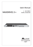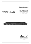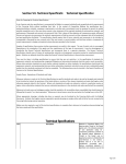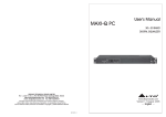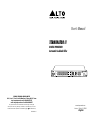
1
User's Manual
TERMINATOR II
DIGITAL PROCESSOR
Automatic Feedback Killer
CH 1
CH 1
CHANNEL 1
1
2
3
4
5
6
7
8
9
10
11
12
13
14
15
16
17
18
19
20
21 22
23
TERMINATOR II
1/40
-10
1/80
MUSIC
FILTERS
CH 2
1/40
24
CH 2
CHANNEL 2
BYPASS
1/5
SPEECH
1/80
1/5
MUSIC
SPEECH
LIVE MODE VARIATIONS
0
+10 +18
CLIP
AUTOMATIC
FEEDBACK
KILLER
INPUT LEVEL dBu
ON
OFF
POWER
SEIKAKU TECHNICAL GROUP LIMITED
NO. 1, Lane 17, Sec. 2, Han Shi West Road, Taichung 40151, Taiwan
http://www.altoproaudio.com Tel: 886-4-22313737
email: [email protected] Fax: 886-4-22346757
All rights reserved to ALTO. All features and content might be changed
without prior notice. Any photocopy, translation, or reproduction of part of this
manual without written permission is forbidden. Copyright c 2007 Seikaku Group
NF02949-1.2
www.altoproaudio.com
Version 1.2 April 18, 2008
English
IMPORTANT SAFETY INSTRUCTION
CAUTION
RISK OF ELECTRIC SHOCK
DO NOT OPEN
TO REDUCE THE RISK OF ELECTRIC SHOCK
PLEASE DO NOT REMOVE THE COVER OR
THE BACK PANEL OF THIS EQUIPMENT.
THERE ARE NO PARTS NEEDED BY USER
INSIDE THE EQUIPMENT. FOR SERVICE,
PLEASE CONTACT QUALIFIED SERVICE
CENTERS.
WARNING
To reduce the risk of electric shock
and fire, do not expose this equipment
to moisture or rain.
Dispose of this product should
not be placed in municipal waste
and should be separate collection.
11. Move this Equipment only with a cart,
stand, tripod, or bracket,
This symbol, wherever used, alerts you to the
specified by the
presence of un-insulated and dangerous voltages
manufacturer, or
within the product enclosure. These are voltages that
sold with the
may be sufficient to constitute the risk of electric
Equipment. When
shock or death.
a cart is used, use
This symbol, wherever used, alerts you to
caution when
important operating and maintenance instructions.
moving the cart /
Please read.
equipment
Protective Ground Terminal
combination to
AC mains (Alternating Current)
avoid possible
Hazardous Live Terminal
injury from tip-over.
ON: Denotes the product is turned on.
12. Permanent hearing loss may be caused by
OFF: Denotes the product is turned off.
exposure to \ extremely high noise levels.
CAUTION
The US. Government's Occupational Safety
Describes precautions that should be observed to
and Health Administration (OSHA) has
prevent damage to the product.
specified the permissible exposure to noise
1. Read this Manual carefully before operation.
level.
2. Keep this Manual in a safe place.
These are shown in the following chart:
3. Be aware of all warnings reported
with this symbol.
HOURS X DAY SPL EXAMPLE
4. Keep this Equipment away from water and
90 Small gig
8
moisture.
92 train
6
5. Clean it only with dry cloth. Do not use
95 Subway train
4
solvent or other chemicals.
97 High level desktop monitors
3
6. Do not damp or cover any cooling opening.
100 Classic music concert
2
Install the equipment only in accordance with
102
1,5
the Manufacturer's instructions.
105
1
7. Power Cords are designed for your safety. Do
110
0,5
not remove Ground connections! If the plug
0,25 or less 115 Rock concert
does not fit your AC outlet, seek advice from
a qualified electrician. Protect the power
According to OSHA, an exposure to high SPL in
cord and plug from any physical stress to
excess of these limits may result in the loss of
avoid risk of electric shock. Do not place
heat. To avoid the potential damage of heat, it is
heavy objects on the power cord. This could
cause electric shock or fire.
recommended that Personnel exposed to
equipment capable of generating high SPL use
8. Unplug this equipment when unused for long
hearing protection while such equipment is
periods of time or during a storm.
under operation.
9. Refer all service to qualified service personnel
The apparatus shall be connected to a mains
only. Do not perform any servicing other than
those instructions contained within the
socket outlet with a protective earthing
User's Manual.
connection.
10. To prevent fire and damage to the product,
use only the recommended fuse type as
indicated in this manual. Do not short-circuit
the fuse holder. Before replacing the fuse,
make sure that the product is OFF and
disconnected from the AC outlet.
The mains plug or an appliance coupler is used
as the disconnect device, the disconnect device
shall remain readily operable.
7. WARRANTY
1. WARRANTY REGISTRATION CARD
To obtain Warranty Service, the buyer should first fill out and return the enclosed
Warranty Registration Card within 10 days of the Purchase Date.
All the information presented in this Warranty Registration Card gives the
manufacturer a better understanding of the sales status, so as to provide a
more effective and efficient after-sales warranty service. Please fill out all the
information carefully and genuinely, miswriting or absence of this card will void
your warranty service.
2. RETURN NOTICE
2.1 In case of return for any warranty service, please make sure that the
product is well packed in its original shipping carton, and it can protect your
unit from any other extra damage.
2.2 Please provide a copy of your sales receipt or other proof of purchase with
the returned machine, and give detail information about your return address
and contact telephone number.
2.3 A brief description of the defect will be appreciated.
2.4 Please prepay all the costs involved in the return shipping, handling and
insurance.
3. TERMS AND CONDITIONS
3.1 LTO warrants that this product will be free from any defects in materials
and/or workmanship for a period of 1 year from the purchase date if you
have completed the Warranty Registration Card in time.
3.2 The warranty service is only available to the original consumer, who purchased
this product directly from the retail dealer, and it can not be transferred.
3.3 During the warranty service, LTO may repair or replace this product at its
own option at no charge to you for parts or for labor in accordance with the
right side of this limited warranty.
3.4 This warranty does not apply to the damages to this product that occurred
as the following conditions:
Instead of operating in accordance with the user's manual thoroughly, any abuse
or misuse of this product.
Normal tear and wear.
The product has been altered or modified in any way.
Damage which may have been caused either directly or indirectly by another
product / force / etc.
Abnormal service or repairing by anyone other than the qualified personnel or
technician.
And in such cases, all the expenses will be charged to the buyer.
3.5 In no event shall LTO be liable for any incidental or consequential damages.
Some states do not allow the exclusion or limitation of incidental or
consequential damages, so the above exclusion or limitation may not apply to
you.
3.6 This warranty gives you the specific rights, and these rights are compatible
with the state laws, you may also have other statutory rights that may vary
from state to state.
11
QUICK START
1. TERMINATOR II QUICK START - SET UP MODE
1.1 After connecting TERMINATOR II to the mixer channels or subgroups follow
these points:
1.2 Press and hold the BYPASS button (for more than 4 seconds) related to
the channel you want to set up (CHANNEL 1 or CHANNEL 2): all 24 filter
leds will start flashing
1.3 Start generating intentional feedbacks increasing slowly the GAIN/VOLUME
on the mixer: TERMINATOR II will activate gradually the filters and the
correspondent leds will light
1.4 Usually 10 to 16 filters are enough to guarantee a safe set up without
modifying the audio timbre
1.5 Remember you can use up to 2 independent channels connected to
TERMINATOR II
1.6 To exit SET UP MODE and to STORE the fixed filter press quickly the related
channel BYPASS button: all filter leds turn on for a few seconds, then only
the stored ones keep on lighting
1.7 Now TERMINATOR II is set on LIVE MODE
2. TERMINATOR II QUICK START - LIVE MODE
2.1 During the performance the accidental LIVE feedbacks are automatically
detected and killed: a new led will light to indicate the activation of a new
LIVE filter
2.2 If occasionally all 24 filters are activated (all filter leds on) and new LIVE
feedback occurs, TERMINATOR II is able to kill the new feedback substituting
the oldest less-used filter: the correspondent led will start flashing
2.3 You can operate in real time on the LIVE MODE VARIATIONS to adjust the
filter Q according to your audio source: generally for Music we suggest to
turn the knob towards 1/80th, for Speech towards 1/5th)
2.4 If you need to RESET the LIVE filters (keeping the FIXED ones previously
stored during the SET UP MODE) press and hold the BYPASS button for
about 2 seconds till only the FIXED filter leds keep on lighting
2.5 If you need to RESET completely TERMINATOR II and start a new SET UP,
press and hold the BYPASS button for more than 4 seconds till all 24 filter
leds will start flashing
IN THIS MANUAL:
1.
2.
3.
4.
5.
6.
7.
INTRODUCTION........................................................................1
FEATURES...............................................................................1
CONTROL ELEMENTS..............................................................2
USER SETUP...........................................................................4
INSTALLATION & CONNECTION.................................................7
TECHNICAL SPECIFICATIONS..................................................10
WARRANTY...........................................................................11
1. INTRODUCTION
Thank you for your purchasing of the LTO TERMINATOR II. The TERMINATOR II
is a Dual Channel Digital Processor. It is designed to provide state of the art
Feedback elimination processing, for fixed installation or live event, while
maintaining a simple and intuitive control interface.
The TERMINATOR II provides up to 24 filters per channel (CH1 & CH2), offers
independent selectable modes, live filters lift, process bypasses, continuously
variable types of filtration, with widths between 1/80th and 1/5th Octave of which
are all available on a intuitive user interface front panel.
Enjoy your TERMINATOR II and make sure to read this Manual carefully before
operation!
6. TECHNICAL SPECIFICATION
Analog Inputs
2 x female XLR and 2 x 1/4" TRS
Input impedance
Max Input line level
Analog Outputs
2 x male XLR and 2 x 1/4" TRS
Output impedance
Max Output level
A/D Performance
Dynamic Range
A/D Conversion
D/A Performance
Dynamic Range
D/A Conversion
System Performance
Sample Rate
Dynamic Range
THD+N %
S/N Ratio
Frequency Response
Inter channel Crosstalk
Crosstalk input to output
Power
Requirement
Operating
Voltage
Power Consumption
Physical
Dimension
Net Weight
Electronically Balanced / Unbalanced, RF filter suppressor
30k ohm Balanced / 15k ohm Unbalanced
+20.5 dBu
Electronically Balanced / Unbalanced, RF filter suppressor
100 Ohm Balanced / 50 Ohm Unbalanced
+14.5 dBu
114 dB, A-weighted
24 bit
100 dB, A-weighted
24 bit
48 kHz
100 dB, A-weighted
0.01 %, 1 kHz
100 dB, A-weighted
20 Hz to 20 kHz, +/- 0.5 dB
100 dB, A-weighted
100 dB, A-weighted
230 VAC 50/60 Hz 115 VAC 50/60 Hz
15 W
483 x 195 x 44 mm
3.1kg
2. FEATURES
24 Programmable Filters per Channel
Dual Independent Channel Processing
Live and Fixed Filter Modes
Automatic Live Filter Release
Selectable Application of LTO proprietary Filter Variations (Music/Speech)
2 Input Channel Metering
24 LED Filter Metering per Channel
2 XLR and 2 x TRS Electronically Balanced Inputs and Outputs
Selectable Operating Level Switches (+4 dBu / -10 dBv)
Rear Panel Lockout Switch
1
10
3.
ELEMENTS
5. CONTROL
INSTALLATION
AND CONNECTION
ON LINE with the Outputs of the Mixer
SP
OT
LI
3.
3. CONTROL
CONTROLELEMENTS
ELEMENTS
GH
T
Front Panel:
1- Connect the Outputs L-R from the mixer to the inputs CH 1 & CH 2 of
TERMINATOR II with the XLR or TRS (tip-ring-sleeve) stereo jack.
2- Connect the Outputs CH1 & CH2 of TERMINATOR II at the Inputs of power
amplifiers.
3- Set the sensitivity at +4 dBu on the TERMINATOR II and adjust the L-R fader
control on the MIXER for having a necessary level on TERMINATOR II.
For maximum performance and proper operation, the average input signal should
consistently light up at the 0 dBu LED and the +10 dBu LED lighting occasionally.
CH 1
CH 1
CHANNEL 1
1
2
3
4
5
6
7
8
9
10
11
12
13
14
15
16
17
18
19
20
21 22
23
CH 2
1/40
TERMINATOR II
1/40
24
-10
CH 2
CHANNEL 2
1/80
MUSIC
FILTERS
BYPASS
1
2
1/5
SPEECH
1/80
1/5
MUSIC
SPEECH
LIVE MODE VARIATIONS
3
0
+10 +18
CLIP
ON
OFF
POWER
INPUT LEVEL dBu
4
AUTOMATIC
FEEDBACK
KILLER
5
6
1 Filters LEDs
The TERMINATOR II offers 24 notch filters (RED LED) for each channel, which
are used to indicate the number of active notch filter. The LEDs that always
blink for each channel is the last Live inserted notch filter.
2 Bypass
MS152
a-This button is used to bypass the notch filters in the signal path by pressing
quickly (about 1 second).
b-Pressing and holding the BYPASS button (about 2 Sec) is used to reset
the LIVE filters (CLEAR 2 Sec.).
c-Pressing and holding the BYPASS button (more than 4 Sec.) is used to reset
the fixed filters and enter the SETUP Mode (SETUP 4 Sec.).
For more information of filter reset, please see the Clearing Filters in
the USER SETUP section.
MS152
SPK IN
SPK IN
AMP OUTPUT CH1-CH2
3 LIVE Mode Variations
D1
SIG CLIP PROT
18
20
16
18
22
24
26
12
6
28
CH1
500W
SIG CLIP PROT
30 (dB)
20
16
2
22
24
26
12
6
28
CH2
30 (dB)
AMP IN CH1-CH2
OUTPUT CH1-CH2
CH 1
CH 1
CHANNEL 1
1
2
3
4
5
6
7
8
9
10
11
12
13
14
15
16
17
18
19
20
21 22
23
CH 2
TERMINATOR II
1/40
-10
1/80
MUSIC
FILTERS
1/40
24
CH 2
CHANNEL 2
BYPASS
1/5
SPEECH
1/80
1/5
MUSIC
SPEECH
LIVE MODE VARIATIONS
INPUT CH1-CH2
0
+10 +18
INPUT LEVEL dBu
CLIP
AUTOMATIC
FEEDBACK
KILLER
ON
OFF
This knob is used in LIVE MODE to select the application of ALTO proprietary
notch filter, independently on CH1 & CH2.
th
th
Each selected mode controls the width (1/80 to 1/5 ) of the notch filter used
to remove the feedback, the velocity of the filter activation and the sensibility
in the feedback analysis.
POWER
4 Input Level Bar Graph
MIX OUT L-R
These four LEDs indicate input level of the TERMINATOR II with a range from
-10 dBu to +18 dBu.
NOTE: For maximum performance and proper operation, the average input signal
should consistently light up at the 0 dBu LED and the +10 dBu LED lighting
occasionally.
5 Clip LED
This LED indicates that there is signal clipping at the Inputs. If necessary,
verify the correct position of input selector -10dBv /+4dBu, or setting the
level of the chain with a external pink noise signal.
6 Power Switch
It switches your TERMINATOR II On/Off.
9
2
SP
OT
LI
3.
3.CONTROL
CONTROLELEMENTS
ELEMENTS
GH
5. CONTROL
INSTALLATION
AND CONNECTION
3.
ELEMENTS
T
Insert on the SUB GROUP/MAIN L-R of the Mixer
1- Connect the TRS (tip-ring-sleeve) stereo jack into the Mixer SUB GROUP/
MAIN L-R, Insert socket.
Rear Panel:
CHANNEL 2
AC INPUT
100-120V /220-240V 60-50Hz
Rated Power Consumption 20W
TIP/PIN 2
RING/PIN 3
SLEEVE/PIN 1
VOLTAGE SELECTOR
FUSE:
220-240V: T315mAL 250VAC
100-120V: T500mAL 250VAC
REPLACE FUSE WITH CORRECT
TYPE ONLY
Apparaten skall anslutas till
jordat uttag nar den ansluts
till ett natverk
7
CHANNEL 1
TIP/PIN 2
RING/PIN 3
SLEEVE/PIN 1
+4 dBU
-10 dBV
~100-120
VAC
~220-240
VAC
8
OUTPUTS
ON
INPUTS
9
TIP/PIN 2
RING/PIN 3
SLEEVE/PIN 1
LOCK
11
TIP/PIN 2
RING/PIN 3
SLEEVE/PIN 1
+4 dBU
-10 dBV
OFF
OUTPUTS
INPUTS
10
2- C onne ct t he S end stereo jack (unbalanced) to the CH1 Input of TERMINATOR II
and the C H1 Output of TERMINATOR II with a Return stereo jack (unbalanced).
3- Set the sensitivity at -10 dBu on the TERMINATOR II and adjust the SUB
GROUP/ MAIN L-R, fader control on the MIXER for having a necessary level
on TERMINATOR II.
For maximum performance and proper operation, the average input signal should
consistently light up at the 0 dBu LED and the +10 dBu LED lighting occasionally.
7 AC Inlet and Fuse holder
Standard IEC receptacle. Connect your TERMINATOR II to the AC Inlet with
the supplied AC power cord. Before powering up your TERMINATOR II for the
firs t ti me, make certain the stated power requirement of the unit matches the
voltage supplied by the AC socket.
CH 1
CH 1
CHANNEL 1
1
2
3
4
5
6
7
8
9
10
11
12
13
14
15
16
17
18
19
20
21 22
23
TERMINATOR II
1/40
-10
1/80
MUSIC
FILTERS
CH 2
1/40
24
CH 2
CHANNEL 2
BYPASS
1/5
SPEECH
1/80
1/5
MUSIC
SPEECH
LIVE MODE VARIATIONS
0
+10 +18
INPUT LEVEL dBu
CLIP
AUTOMATIC
FEEDBACK
KILLER
ON
OFF
POWER
TU
RN
RE
RE
ND
SE
ND
SE
8 Voltage Selector
TU
RN
If the fuse blows, replaced with a fuse of the correct type only.
This switch has two choices for voltage, 100-120 VAC or 220-240 VAC.
9 Input/Output Connectors
Two types of input connectors are provided for input connections: 2 x female
locking XLR type connectors, and 2 x 1/4" TRS jack connectors (tip-ring-sleeve).
The maximum input level that the processor can accept is +20 dBu
(ref.: 0.775Vrms).
INSERT SUB 2
INSERT SUB 1
10 Operating Level Switch
This button allows you to select between either +4 dBu or -10 dBv nominal
operating level.
11 Lock Switch
This switch locks/unlocks all access to the front panel of the TERMINATOR II.
3
8
3.
ELEMENTS
5. CONTROL
INSTALLATION
AND CONNECTION
4. USER SETUP
1 Setting Audio System
Insert on the MIC channel
1- Connect the TRS (tip-ring-sleeve) stereo jack into the mixer MIC channel,
Insert socket.
2- Connect the Send stereo jack (unbalanced) to the CH1 Input of TERMINATOR II
and the CH1 Output of TERMINATOR II with a Return stereo jack (unbalanced).
3- Set the sensitivity at -10 dBu on the TERMINATOR II and adjust the MIC Gain
control on the MIXER for having a necessary level on TERMINATOR II.
4- Repeat the same step connections for the CH2 of TE RMINATOR II if you like
to use.
For maximum performance and proper operation, the average input signal should
consistently light up at the 0 dBu LED and the +10 dBu LED lighting occasionally.
CH 1
CH 1
CHANNEL 1
1
2
3
4
5
6
7
8
9
10
11
12
13
14
15
16
17
18
19
20
21 22
23
N
TU
R
RE
RN
TU
ND
SE
ND
SE
RE
TERMINATOR II
1/40
-10
1/80
MUSIC
FILTERS
CH 2
1/40
24
CH 2
CHANNEL 2
BYPASS
1/5
SPEECH
1/80
1/5
MUSIC
SPEECH
LIVE MODE VARIATIONS
0
+10 +18
INPUT LEVEL dBu
CLIP
AUTOMATIC
FEEDBACK
KILLER
ON
OFF
POWER
There are three basic ways you can use the TERMINATOR II combine with your
audio system. It can be:
1. Connected to a MIC channel of a MIXER, into the "Insert" jack (send/return).
2. Connected to the SUBGROUP/MAIN OUTPUTS (L/R) of a MIXER into the
"Insert" jack (send/return).
The connection of TERMINATOR II to Insert points, is probably the best
selection, the levels present in most mixers are pre-fader, (normally 10 dBu)
and flow direct to TERMINATOR II. In this way any fader level variations do
not modified the setup of TERMINATOR II.
For the best performance and proper operation, the average input signal
should consistently light up at the 0 dBu LED and the +10 dBu LED lighting
occasionally.
3. Connected "ON LINE" between mixer and PA system. From output of the Mixer
to input of TERMINATOR II and from Output of TERMINATOR II to PA input
(Stereo Amplifier).
The above setup is used when insert points are not available, set the
TERMINATOR II at +4 dBu, this value is correct when you connect the
outputs of any mixer directly to the input of TERMINATOR II.
For the best performance and proper operation, the average input signal
should constantly light around 0 dBu LED and the +10 dBu LED should light
only occasionally.
2 SETUP & LIVE Mode
INSERT MIC 2
INSERT MIC 1
MIC 1
The TERMINATOR II offers a total number of 24 notch filters for each channel
(CH 1/CH 2) and two main operation modes:
a-SETUP mode, with the fixed filters.
b-LIVE mode, with the free filters not used in SETUP mode.
MIC 2
The SETUP mode is used to detect and remove feedback problems in the audio
system due to the microphone placement, different environments shapes, etc.
Once these filters are set, they can't be removed unless you reset then again.
The LIVE mode is used to detect and remove feedback in "real-time", during
the musical events.
The free filters, not used in SETUP mode, automatically work in LIVE mode, the
last filter included blink.
1. Using SETUP Mode (SOUND CHECK)
Fixed filters are set before a performance in a process called ringing out a
system, this is done after all other setting system has been done.
a-First, bring down the main mix, turn off all music sources and open the
MIC (if you use Vocalist) or the different MIC (if you use a Sub-Group).
7
4
4. USER SETUP
4. USER SETUP
b-Place the TERMINATOR II in SETUP Mode by pressing and holding the BYPASS
button for more than 4 seconds.
c-All the 24 LEDs and the BY PASS LED will start flashing, indicating SETUP
mode is selected for CH1 or CH2 or together.
d-Set the level of each CHANNEL with PFL and slowly turn up the Main Mixer
Volume, raising the gain of the system, until feedback occurs.
e-The TERMINATOR II will detect and remove feedback by placing notch filters
on the proper frequencies. Continue to slowly raise the gain until all
feedbacks have been eliminated, then exit from SETUP Mode by pressing
and releasing the BYPASS button quickly.
All LED turn ON for few seconds, indicating fixed filters are STORED and
automat ically LIVE Mode is selected, the remaining filters are available in LIVE
MODE.
If all 24 filters have been used in SETUP Mode, the SETUP Mode is left
automatically and no more filters are available in LIVE Mode.
2. Using LIVE Mode (REAL TIME)
The TERMINATOR II operates normally in LIVE Mode (24 notch filters minus
the fixed used filters ). Live Mode filters are set on the feedback frequency
as soon as a new feedback is detected, according to the knob position of
the sel ected LIVE Mode Variations (from MUSIC to SPEECH).
If all LIVE filters are used and a new feedback occurs, the oldest LIVE filter
is cleared and reallocate to the new feedback frequency (the correspondent
led will light).
The TERMINATOR II will continue to search feedback frequency through the
LIVE notch filters.
3 CLEARING FILTERS
To reset the LIVE filters, press and hold the BYPASS button on the selected
channel (for about 2sec till the live filter leds will switch off). The currently
active filters will be cleared and the assigned LED will turn off.
If you wish to "reset" all the filters, continue to hold the BYPASS button
(more than 4 seconds) until all filter LEDs are "blinking", indicating that you
have entered the SETUP Mode and that all filters FIXED and LIVE have been
cleared.
4 LOCK ON/OFF
When you finished setting the TERMINATOR II, you can save your setup, switch
ON the LOCK selectors in the rear panel.
After this it will be impossible to operate on fro nt pane l.
5 AUTOMATIC FILTER RELEASE
The ALTO TERMINATOR II provides the user with 24 notch filters, for each
channel, they are enough for normal performances. If several
numbers of filters are required, (more than 16), we strongly recommend to
operate a new setup of the sound system.
Anyway, even if the TERMINATOR II uses very narrow notch filters, accordingly
with the selected application type, unused notch filters must be avoided, to
always guarantee the best audio performance.
The TERMINATOR II constantly monitors the status of the LIVE filters and
automatically removes the ones that are no longer necessary.
th
MUSIC High Q mode, (use notch filters at 1/80 Octave), continuously variable
until SPEECH Low Q mode, (use notch filters at 1/5th Octave).
+3
+3
+2
Music High-1/80th Octave
+1
+2
+1
0
0
-1
-1
-2
d
B -3
u -4
-2
d
-3 B
-4 u
-5
th
Speech 1/5 Octave
-5
-6
-6
-7
-7
-8
-8
-9
700
750
820 850 900 .95k 1k
1.2k
-9
Hz
ALTO Notch Filter Q Diagram
5
6