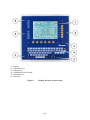
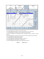
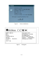
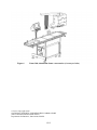
1
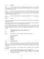
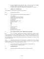
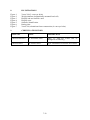
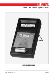
(UK/0126/0064) MI-006 United Kingdom of Great Britain and Northern Ireland Certificate of EC type-examination of a measuring instrument Number: UK/0126/0064 rev 1 issued by the Secretary of State for Business, Innovation and Skills Notified Body Number 0126 In accordance with the requirements of the Measuring Instruments (Automatic Catchweighers) Regulations 2006 (SI 2006/1257) and the Measuring Instruments (NonPrescribed Instruments) Regulations 2006 which implement, in the United Kingdom, Council Directive 2004/22/EC, this certificate of EC type-examination has been issued to: Società Cooperativa Bilanciai a.r.l. Via S. Ferrari No 16 41011 Campogalliano Modena Italy in respect of a family of automatic checkweighers / catchweighers designated the Venus 300 and having the following characteristics: Maximum capacity Minimum capacity Scale interval Number of scale intervals Maximum belt speed Accuracy classes Max ≤ 40 000 g Min ≥ 50 e for Class X Min ≥ 20 e for Class Y e≥1g n ≤ 6000 ≤ 70 m/min XIII(1) and Y(a) The necessary data (principal characteristics, alterations, securing, functioning etc) for identification purposes and conditions (when applicable) are set out in the descriptive annex to this certificate. This revision replaces previous versions of this certificate. Signatory: for Issue Date: 23 November 2009 Valid Until: 04 October 2019 Reference No: T1108/0056 G. Glas Chief Executive National Weights & Measures Laboratory (Part of National Measurement Office) Department for Business, Innovation & Skills Stanton Avenue Teddington Middlesex TW11 0JZ United Kingdom Descriptive Annex 1 INTRODUCTION This family of instruments, designated the Venus 300, comprises patterns designed to operate as automatic checkweighers (Category X) and/or automatic weight or weight/price labellers (Category Y). The instruments comprise a plastic box display and user interface, a weighing device and mechanical handling facilities (Figure 1). The instruments may be fitted with reject devices when operating as a checkweigher, and/or up to 4 thermal label printers when operating as weight or weight/price labeller. The instruments are designed to weigh packs statically. Pricing, pack and labelling information is stored in files called PLUs selectable by the operator for the commodity or labels being processed. Labels are printed for the above transaction data and are applied to the packs automatically. 2 FUNCTIONAL DESCRIPTION 2.1 Mechanical 2.1.1 The instrument console is constructed in plastic. The framework is a fabricated floor standing stainless steel frame. On the frame are mounted the modular conveyor sections (weigh platform). The conveyors type, number, size and shape are not restricted. The conveyor can be equipped with one of a number of reject devices, including a flipper, drop flap, ram or air blast (Category X), and/or thermal label printers (Category Y). 2.1.2 The control cabinet is located behind the display and user interface unit and is pole-mounted. The instrument is designed to be permanently installed and is fitted with a level indicator located on the weigh platform. 2.1.3 Weigh platform 2.1.3.1 The weighing device comprises a single strain gauge load cell located below the centre of the weigh conveyor (Figure 2). The load cell may be mounted longitudinally or transversally. The load cell may be one of the following: Venus 300 “3-6” Emax (kg) HBM PW22 C3 Vmin≥10000 Tedea 1042 C3-C6 Vmin=10000 Scaime AB Venus 300 Venus 300 Venus 300 Venus 300 Venus 300 “3” “6” “12” “15” “40” Emax (kg) Emax (kg) Emax (kg) Emax (kg) Emax (kg) 20 10 20 20 10 20 / 20 30 20 30 15 / / / C5 Vmin=10000 2/12 20 30 20 30 / / / 100 75 50 / 90 65 150 100 75 / 185 130 90 65 Any compatible load cell may be used providing the following conditions are met: − − − − − − There is a respective OIML Certificate of Conformity (R60) or a test certificate (EN45501) issued for the load cell by a Notified Body responsible for type examination under Directive 2009/23/EC, or a parts certificate (WELMEC Guide 8.8) issued by a Notified Body responsible for type examination (Annex B, MI-006) under Directive 2004/22/EC. The certificate contains the load cell types and the necessary load cell data required for the manufacturer’s declaration of compatibility of modules (WELMEC 2, Issue 5, May 2009, No 11), and any particular installation requirements. A load cell marked NH is allowed only if humidity testing to EN45501 has been conducted on this load cell. It is not a load cell with digital output The characteristics of the replacement load cell such as nlc, Y, Z are the same or better that the load cell tested dynamically (HBM PW22 C3, capacity 20 kg) The design of the load cells and the material are the same No oil damper is used 2.1.3.2 The system uses photocells to determine where the packs have to be stopped on the weigh platform. The instrument captures the weight when the stability of equilibrium has been reached. The “Auto Zero” mode is active when there are no packs on the platform. 2.2 Electrical 2.2.1 The control cabinet, located behind the display, houses the electrical hardware. The control cabinet can be accessed by opening the rear plastic shell. Inside are the A/D converter type 404510 board, main board with CPU type AMD Geode chipset GX 466 333 MHz or equivalent, mains power supply, CPU power supply (input 90/240Vac, output +5 V). 2.2.2 The motor drivers and appropriate relays are located in a sliding drawer under the conveyors. 2.2.3 The pole-mounted display and user interface unit (Figure 3) comprises an alphanumerical keyboard and LCD display with navigation keys. The display is segregated in distinct areas (Figure 4), and allows viewing of weighing parameters and results as well as access to the instrument various functions. 2.3 Devices The instrument has the following devices: − − − − − − − − − Automatic zero setting device active during automatic operation (at least once every 17 min) Semi-automatic zero-setting (≤ 4% max) Initial zero-setting (≤ 20% max) Pre-set tare device (subtractive) Static calibration, not accessible to the user Belt speed setting, accessible to the user (access password protected level 1) Internal memory for storage of batch data (category X) Device acting upon significant faults Screen check at power-up 3/12 − − High resolution mode (0.1e) for testing purposes, not accessible to the user Operation under Category X or Y selection device, accessible to the user (access password protected level 2, see note below) Note: The parameter allowing the instrument to operate as category X and/or Y is set at initial verification and part of the legally relevant parameters, and is therefore protected. The user has no access to any mode of operation disabled at initial verification. 3 TECHNICAL DATA 3.1 The Venus 300 has the following technical characteristics: Model Venus 300 “3-6” ≤ 3/6 kg Dualinterval 20 g 50 g 1/2 g Venus 300 “3” Venus 300 “6” Venus 300 “12” Venus 300 “15” Venus 300 “40” ≤ 3 kg ≤ 6 kg ≤ 12 kg ≤ 15 kg ≤ 40 kg 20 g 50 g 1g 20 g 50 g 1g 40 g 100 g 2g 100 g 250 g 5g 200 g 500 g 10 g ≤ 2x3000 ≤ 3000 ≤ 6000 ≤ 6000 ≤ 3000 ≤ 4000 Max capacity: (Max) Min capacity, cat Y: (Min) cat X: Scale interval (e): Max number of scale intervals (n): Tare (T): Cat X and Y Climatic environment - 2000e (single interval) -2000e1 (dual interval) 0 to +40 °C / Closed, non-condensing EM classification: Power supply Accuracy class E1 and E2 240 Va.c. 50 Hz XIII(1) and Y(a) Conveyors’ speed is limited to 70 m/min for loads up to 6 kg, and 60 m/min for greater loads. 3.2 Documentation and drawings Description User Manual Venus 300 dimensional drawings Venus 300 assembly drawings Venus 300 block diagram Drawing / Document number 81320076 Venus PE 130 acciaio.pdf Venus PE 140 aluminium.pdf Elenco materiale per venus 300.doc Documentazione tecnica.doc Rev. 1 0 0 0 1 A/D converter schematics CPU schematics 404511A1-A2-A3.pdf 57130006_EA106sch.pdf 57130006_EA106JL.pdf 57130006_SA00600man.pdf 57130016-CPU1433.pdf 46050014.doc 0 A01 A01 S07 1.0 0 Main board schematics Power supply schematics 4/12 3.3 Software 3.3.1 The A/D converter software is designated “Bilanciai 491021 x.x”, with x.x the release number that may change following minor modifications. The A/D converter software is completely legally relevant. 3.3.2 The main board software comprises two parts. The legally relevant part is designated “Sw.Metr: 3.x.xx” (e.g. Sw.Metr: 3.1.1e), with x.xx the release number that may change following minor modifications. The non-legally relevant part can be freely modified (currently designated VER.SW 4.3.11.Q). 3.3.3 (Figure 5). The above information can be displayed by entering “ALT+V” via the keypad 3.3.4 Security Legally relevant parameters are protected by a calibration and set-up switch located inside the sealed control cabinet. Downloading of software can only be carried out by authorised personnel, and any download of legally relevant software needs access to the calibration-setup switch. An event logger automatically records all relevant data (date and time, A/D converter board software version with checksum, mercury board legally relevant software version with checksum, and entry for success), which can be displayed by entering “ALT+W” via the keypad. 4 PERIPHERAL DEVICES AND INTERFACES 4.1 Interfaces 4.1.1 The instrument may have a number of the following interfaces: − − − − − 4.2 RS232/RS485/RS422 Parallel port Ethernet Analogue Keyboard Peripheral devices 4.2.1 The instrument may be connected to any peripheral device that has been issued with a parts certificate by a Notified Body responsible for Annex B (MI-006) under Directive 2004/22/EC in any Member State and bears the CE marking of conformity to the relevant directives; or A peripheral device without a parts certificate may be connected under the following conditions: − − it bears the CE marking for conformity to the EMC Directive; it is not capable of transmitting any data or instruction into the weighing instrument, other than to release a printout, checking for correct data transmission or validation; 5/12 − − 5 it prints weighing results and other data as received from the weighing instrument without any modification or further processing; and it complies with the applicable requirements of Paragraph 8.1 of Annex I. APPROVAL CONDITIONS The certificate is issued subject to the following conditions: 5.1 Legends and inscriptions 5.1.1 The instrument bears the following legends (Figure 6): ‘CE’ marking Supplementary metrology marking Notified body identification number Accuracy class Serial number Manufacturers mark or name Certificate number Max Min e= T= Temperature-range Power supply Pneumatic pressure Maximum speed / pack rate 6 LOCATION OF SEALS AND VERIFICATION MARKS 6.1 The ‘CE’ marking, supplementary metrology marking and certificate number are located on the side of the control cabinet. The CE mark shall be impossible to remove without damaging it. The data plate shall be impossible to remove without it being destroyed. The markings and inscriptions shall fulfil the requirements of Paragraph 9 of Annex I of the Directive 2004/22/EC. 6.2 Components that may not be dismantled or adjusted by the user (cabinet enclosure, load cell connection) will be secured by either a wire and seal or tamper evident label and securing mark. The securing mark may be either: − − a mark of the manufacturer and/or manufacturer’s representative, or an official mark of a verification officer. 7 ALTERNATIVES 7.1 Having an aluminium frame construction, as shown in Figure 7. 6/12 8 ILLUSTRATIONS Figure 1 Figure 2 Figure 3 Figure 4 Figure 5 Figure 6 Figure 7 Venus 300 (3 conveyor belts) Weigh platform (longitudinally mounted load cell) Display and user interface unit Display areas Software identification Rating plate Venus 300, aluminium frame construction (4 conveyor belts) 9 CERTIFICATE HISTORY ISSUE NO. DATE DESCRIPTION UK/0126/0064 rev 1 23 November 2009 Table 3.1: Min for Venus 300 “6” changed to 20 and 50 g UK/0126/0064 05 October 2009 Type examination certificate first issued. 7/12 Figure 1 Figure 2 Venus 300 (3 conveyor belts) Weigh platform (longitudinally mounted load cell) 8/12 1) 2) 3) 4) 5) 6) Display Functional keys Editing keys Alphanumerical keyboard Summing keys Date keys Figure 3 Display and user interface unit 9/12 1. Area that displays the pathway of the activated menu 2. Area that displays the preset tare value in the selected unit of measurement 3. Area that displays the weight in the selected unit of measurement 4. Area that displays the metrological data: maximum capacity, minimum capacity, division 5. Area that displays the unitary price in the selected currency and unit of measurement 6. Area that displays messages for the operator 7. Area that displays the legal instrument (M) 8. Area that displays the function keys and macrofunctions 9. Area that displays the date and time of the system 10. Area for displaying and entering processing data and archives Figure 4 Display areas 10/12 Figure 5 Figure 6 Software identification Rating plate 11/12 Figure 6 Venus 300, aluminium frame construction (4 conveyor belts) Crown Copyright 2009 NATIONAL WEIGHTS AND MEASURES LABORATORY (Part of National Measurement Office) Department for Business, Innovation & Skills 12/12