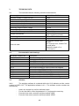
1
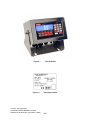
UK/0126/0011
MI-006
EC type-examination certificate
UK/0126/0011 Revision 2
issued by:
The National Measurement Office
Notified Body Number 0126
In accordance with the requirements of the Measuring Instruments (Automatic
Catchweighers) Regulations 2006 (SI 2006/1257) and the Measuring Instruments
(Non-Prescribed Instruments) Regulations 2006 which implement, in the United
Kingdom, Council Directive 2004/22/EC, this EC type-examination certificate has
been issued to:
Avery Weigh-Tronix
Foundry Lane
Smethwick
West Midlands
B66 2LP
United Kingdom
in respect of an automatic catchweighing instrument as described in the descriptive
annex and having the following characteristics:
Maximum capacity Max
Minimum capacity Min
Accuracy class
Y(a)
≤
≥
6000 e
20 e
The necessary data (principal characteristics, alterations, securing, functioning etc)
for identification purposes and conditions (when applicable) are set out in the
descriptive annex to this certificate.
This revision replaces previous versions of the certificate.
Issue Date:
Valid Until:
Reference No:
06 June 2011
04 September 2017
T1110/0006
Signatory: P R Dixon
for Chief Executive
National Measurement Office | Stanton Avenue | Teddington | TW11 0JZ | United Kingdom
Tel +44 (0)20 8943 7272 | Fax +44 (0)20 8943 7270 | Web www.bis.gov.uk/nmo
0135
MID Annex B Rev. 2 01 April 2011
Descriptive Annex
1
INTRODUCTION
This pattern of an automatic catchweighing instrument operates as an automatic weight
labeller (Category Y).
It comprises three conveyors (in-feed, weigh and out-feed), an AWTX 1310 weight indicator
and a label printer. The 1310 indicator is connected to a PC which provides an electronic
data storage facility. A second “down-steam” label printer is also provided. The instrument is
designed to weigh packs statically. Pack and labelling information is stored in data files,
selectable for the commodity and/or labels being processed. Labels are printed with the
required transaction data and are applied to the packs automatically.
2
FUNCTIONAL DESCRIPTION
2.1
Mechanical
2.1.1
The instrument comprises a supporting framework which supports the
motorised weigh conveyor which comprises a conveyor mounted on to a weigh platform
which incorporates the load cell(s).
2.1.2
The weighing module is connected to an AWTX model 1310 weight indicator
(Figure 1) which is connected to a PC. A label printer and barcode scanner are mounted
above the weighing conveyor. Photocells are used to detect the pack and control the
operation of the system. A second label printer, located downstream from the instrument,
applies a “duplicate” label to the outer box.
2.2
Electrical
2.2.1
The electrical hardware is located within the 1310 indicator, label printers, PC
and a control panel. The control panel contains the motor controls and associated power
supplies.
2.2.2
The control of the instrument is provided by the PC, via I/O modules. The
preset tare associated with the product is entered via the 1310 indicator and stored. The PC
requests weight data, including preset tare values, from the 1310 indicator.
2.2.3
The 1310 weight indicator contains all of the electronics associated with the
weighing process and is as described in EC Test certificate GB-1153. The PC runs the Avery
Weigh-Tronix “Weight for Windows” software package as described in EC Test Certificate
GB-1010. This provides an electronic data storage facility, with a unique consecutive number
being generated and printed onto the label. The PC provides a secondary indication of the
weight and various status signals, and is used to select the product being weighed.
2.3
Load cell
Any compatible load cell(s) may be used providing the following conditions are met:
−
There is a respective OIML Certificate of Conformity (R60) or a Test
Certificate (EN45501) issued for the load cell by a Notified Body responsible
for type examination under Directive 2009/23/EEC.
2/8
−
The certificate contains the load cell types and the necessary load cell data
required for the manufacturer's declaration of compatibility of modules
(WELMEC 2, Issue 5, 2009, section 11), and any particular installation
requirements. A load cell marked NH is allowed only if humidity testing to
EN45501 has been conducted on this load cell.
−
The compatibility of load cells and indicator is established by the manufacturer
by means of the compatibility of modules form, contained in the above
WELMEC 2 document.
−
The load transmission conforms to one of the examples detailed in WELMEC
2.4 Guide for Load Cells.
2.4
Printer
2.4.1
The printer is an Advanced Labelling Systems model ALX924/5.
2.5
Devices
2.5.1
The instrument is provided with the following devices:
−
−
−
−
−
−
−
−
−
−
2.6
Semi-automatic zero-setting device (not operable during automatic operation)
Automatic zero-setting device (before every pack)
Zero-tracking device
Zero indicator
Tare weighing or balancing device (not operable during automatic operation)
Preset tare device
Net indicator
Gross (B/G) indicator
Real time clock
Device to determine when stability criteria are fulfilled
Operation
2.6.1
Packs are delivered to the weighing conveyor by the in-feed conveyor. Once
detected by the associated photocell the weighing conveyor is stopped by the 1310 indicator.
The 1310 indicator determines if a stable weight is obtained and the label is then applied.
The barcode scanner reads the barcode on the label. If the data from the scanner is read
correctly, and agrees with the data stored, then the pack continues across the out-feed
conveyor. A second label printer, located downstream from the instrument, produces a
“duplicate” label which is applied to the outer box. A counter is used to synchronise the packs
to ensure that the “duplicate” label is applied to the correct pack.
2.6.2
If an error is detected by the barcode scanner, or if the pack is outside
predefined weight limits, an error signal is generated and the instrument is stopped. The
pack must then be removed from the system and the error acknowledged.
3/8
3
TECHNICAL DATA
3.1
The instrument has the following technical characteristics:
Power supply
Maximum number of scale intervals
Load cell excitation voltage
Minimum load cell impedance
Maximum load cell impedance
Minimum input voltage per verification scale interval
Measuring range minimum voltage
Measuring range maximum voltage
Fraction of maximum permissible error
Climatic environment
Electromagnetic environment
Accuracy class
Load cell cable
3.2
220-240 Vac 50/60 Hz
6000
10 Vdc
28 Ω
1100 Ω
2 µV
12 mV
50 mV
Pind = 0.5
0 °C to 40 °C
Non-condensing (closed)
E1 and E2
Y(a)
6 core with braided outer
screen.
0.5 mm2 per core, flexible PVC
overall jacket
Maximum length = 5 m
(10 m/mm2).
Documentation and drawings
Document / Drawing No.
FDS 103669 V1.4
103669 UM V2.1
50692
50693
51571
51572
53021
50799
50800
51631
51632
3.3
Description
Functional design specification
User manual
Main PCB assembly
Main PCB circuit diagram
Multi-channel analogue output PCB assembly
Multi-channel analogue output board circuit diagram
Network interface PCB assembly
Serial I/O and PSU PCB assembly
Serial I/O and PSU circuit diagram
Display and keyboard interface PCB assembly
Display and keyboard interface PCB circuit diagram
Software
3.3.1
The weighing software is contained within the 1310 indicator and the version
number is 52957-0137. The application software is V1.1. The software version numbers are
accessed by:
−
−
−
−
Hold in the escape key until the indicator beeps.
For the User Menu, enter the password: 111 and press the enter key.
From the User menu, press the soft-key marked “VIEW”.
From the View menu, press the soft-key marked “VERS”.
4/8
3.3.2
The control software is contained within the PC and the version number is
V 2.x, where “x” covers minor software variants. The software version number is accessed by
pressing “help” & “about” when the application is running.
3.3.3
Each label printed and applied to the packs is provided with a unique
consecutive number which is generated by the “Weight for Windows” data storage device
running on the PC.
4
PERIPHERAL DEVICES AND INTERFACES
4.1
Interfaces
The instrument may have the following interfaces:
−
−
−
4.2
Load cell connection (hardwired)
3 x RS232/RS422
1 x powered RS422 (20 mA)
Peripheral devices
The instrument may be connected to any peripheral device that has been issued with a test
certificate or parts certificate by a Notified Body responsible for Annex B (MI-006) under
Directive 2004/22/EC in any Member State and bears the CE marking of conformity to the
relevant directives; or
A peripheral device without a test certificate may be connected under the following
conditions:
5
−
it bears the CE marking for conformity to the EMC Directive;
−
it is not capable of transmitting any data or instruction into the weighing
instrument, other than to release a printout, checking for correct data
transmission or validation;
−
it prints weighing results and other data as received from the weighing
instrument without any modification or further processing; and
−
it complies with the applicable requirements of Paragraph 8.1 of Annex I.
APPROVAL CONDITIONS
The certificate is issued subject to the following conditions:
5.1
Legends and inscriptions
5.1.1
The instrument bears the following legends:
‘CE’ marking
Supplementary metrology marking
Notified body identification number
Accuracy class
Serial number
Manufacturers mark or name
Certificate number
Operating temperature range
5/8
5.2
indicator.
If the instrument is not permanently installed it shall be provided with a level
6
LOCATION OF SEALS AND VERIFICATION MARKS
The “CE” marking, supplementary metrology marking and certificate number
6.1
are located on the mounting plate bracket which is fixed to the main structure of the conveyor
stand. The CE mark shall be impossible to remove without damaging it. The data plate
(Figure 3) shall be impossible to remove without it being destroyed.
The markings and inscriptions shall fulfil the requirements of Paragraph 9 of Annex I of the
Directive 2004/22/EC.
6.2
Access to the configuration and calibration facility for the 1310 weighing
module(s) is via a push button located on the power supply PCB and is accessed through a
hole in the rear of the indicators enclosure. The plastic screw, which prevents access to the
push button, can be secured to the back of the enclosure by a wire and seal.
Components that may not be dismantled or adjusted by the user (including the load cell
junction box if applicable) must be secured by either a wire and seal or a tamper evident
label and securing mark.
The securing mark may be either:
−
−
a mark of the manufacturer and/or manufacturer’s representative, or
an official mark of a verification officer.
7
ALTERNATIVES
7.1
Having the system modified as follows:
−
−
−
The second label printer described in 2.6.1 is removed
The version number for the control software described in 3.3.2 is V 1.x, where
“x” covers minor software variants
The documentation listed in section 3.2 is modified as follows:
104924 FDS V1.x
Functional design specification
104924 UM V1.x
User manual
where “x” covers minor, non-legally relevant documentation variants
7.2
Having the documentation listed in section 3.2 modified as follows:
104907 FDS V2.x
Functional design specification
104415 UM V3.x
User manual
where 'x' covers minor, non-legally relevant documentation variants
8
ILLUSTRATIONS
Figure 1
Figure 2
1310 indicator
Descriptive label
6/8
9
CERTIFICATE HISTORY
ISSUE NO.
DATE
DESCRIPTION
UK/0126/0011
05 September 2007
Type examination certificate first issued.
UK/0126/0011 Rev 1
21 March 2011
Authorised alternative 7.1 added.
UK/0126/0011 Rev 2
06 June 2011
Authorised alternative 7.1 modified to
allow version V1.x for the documentation.
Authorised alternative 7.2 added.
7/8
Figure 1
Figure 2
1310 indicator
Descriptive label
© Crown Copyright 2011
NATIONAL MEASUREMENT OFFICE
Department for Business, Innovation & Skills
8/8