1
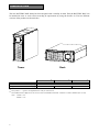
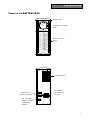
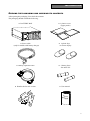
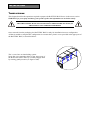
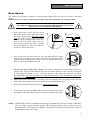
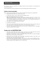
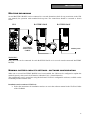
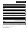
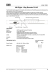
BATTERY BOX User’s Manual MODELS: BX04P240007-- BX04P240009-- BX04C240009-- 1 GB SAFETY GB CAUTION THIS BATTERY BOX CAN ONLY BE CONNECTED TO A UPS. THE CONNECTED UPS MUST HAVE THE SAME BATTERY VOLTAGE. This section of the manual contains instructions that must be strictly complied with as they concern SAFETY. a) Inside the BATTERY BOX are high power batteries, which can generate dangerous voltage even when the input fuses are open. All maintenance operations inside the BATTERY BOX must be EXCLUSIVELY carried out by authorised personnel. b) Total or partial battery voltage may cause electrocution. Do not touch the battery terminals after the outside cover has been removed. c) Batteries should be considered TOXIC WASTE and disposed of consequently. Do not throw spent batteries in the fire as they might explode. Do not try and open the batteries: these are maintenance-free batteries. Contact with the electrolyte is dangerous for skin and eyes and can be toxic. d) The BATTERY BOX contains an energy source inside: the batteries. The expansion sockets may have live voltage even when the UPS is not connected to the mains. e) Do not switch on nor install the BATTERY BOX if it is leaking fluid, or if residual white dust is noticed. f) (for models equipped with battery chargers) As the mains cable of the BATTERY BOX is considered to be a sectioning device, the mains socket to which the BATTERY BOX is connected and/or the rear of the BATTERY BOX must be accessible and easy to disconnect. g) Under hazard conditions, open the fuse-holder disconnecting switches and unplug the power supply cord (where present). h) For battery expansions, use only connectors supplied or authorized by the manufacturer. i) Do not introduce any liquids or foreign matters in the BATTERY BOX. To prevent operation faults due to overheating, do not expose the device to direct sunlight or heat sources. j) Only replace fuses with other fuses of the same type. k) The BATTERY BOX cannot work without an earth connection. During normal operation, avoid disconnecting the UPS connecting sockets and/or the battery-charger mains socket. l) The BATTERY BOX in this series have been designed for professional use and are unsuitable for domestic use. m) This equipment can be installed by anyone, subject to carefully and thoroughly reading this manual. 2 GB USER’S MANUAL GB 3 INTRODUCTION Thank you for choosing our product. The manufacturers are highly specialized in the development and production of uninterruptible power systems (UPS) and related accessories. This manual contains the detailed instructions for the use and installation of the BATTERY BOX for UPSs. To get the most out of this device, please read these instructions and follow them carefully. Keep this manual near the BATTERY BOX. © No part of this manual may be reproduced, even partially, without the manufacturer’s authorization. For purposes of improvements the manufacturer reserves the right to modify the described product at any time and without notice. 4 CONTENTS PRESENTATION 6 VIEWS OF THE BATTERY BOX 7 LED PANEL (ONLY FOR VERSIONS WITH BATTERY CHARGER) 8 DESCRIPTION OF OPERATION 8 INSTALLATION 9 OPENING THE PACKAGING AND CHECKING ITS CONTENTS 9 TOWER VERSION 10 RACK VERSION 11 INSTALLATION PROCEDURE 12 CONNECTING THE BATTERY BOX 12 MULTIPLE EXPANSIONS 13 NOMINAL BATTERY CAPACITY SETTINGS - SOFTWARE CONFIGURATION 13 TROUBLESHOOTING 14 TECHNICAL DATA TABLE 15 5 PRESENTATION The new BATTERY BOX family has been designed with versatility in mind. Thus the BATTERY BOX can be installed in tower or rack version according to requirements by using the handles kit. The two different versions of the product are shown below: Tower Rack BX04P240007-Nominal capacity Dimensions H x L x P Weight (1) (2) 7 63 BX04P240009-- (1) 9 455 x 175 x 660 (2) 65 BX04C240009-9 67 The symbol “-” replaces an alphanumeric code for internal use The H dimension is different in the rack version with handles mounted: 483mm x 175mm x 660mm (H x L x W) Note: 175mm = 4U 483mm = 19” 6 [Ah] [mm] [Kg] (1) (1) PRESENTATION VIEWS OF THE BATTERY BOX Release slots Extractable / rotatable mask Removable front panel Front view Ventilation grid Fuse-holder disconnecting switches Connectors for battery expansion IEC 10A input (only in versions with battery charger) Rear view 7 PRESENTATION LED PANEL (ONLY FOR VERSIONS WITH BATTERY CHARGER) = MAINS PRESENT LED (green): when lit it means the mains is present. = BATTERY CHARGER OPERATING LED (yellow): when lit it means the batteries are being charged DESCRIPTION OF OPERATION The BATTERY BOX contains the batteries which can increase the operating time of uninterruptible power systems (UPS) in extended black-out conditions. The number of batteries contained within can vary depending on the type of UPS the BATTERY BOX is intended for. The utmost care must therefore be taken to ensure that the battery voltage of the BATTERY BOX is the same as the voltage allowed by the UPS. The BATTERY BOX may contain its own battery charger in optimized switching technology for the charging of its batteries. The use of a battery charger for each BATTERY BOX allows fast recharge times to be obtained regardless of the number of batteries and without overloading the battery chargers within the UPS. Further BATTERY BOXES could also be connected in parallel to form a chain able to obtain any amount of back-up time when there is no mains power. 8 INSTALLATION OPENING THE PACKAGING AND CHECKING ITS CONTENTS After opening the packaging, first check the contents. The packaging should contain the following: BATTERY BOX 3 plastic covers (upper panels) 2 plastic keys to release display Power cable (only for models with battery charger) Battery expansion cable Handles kit for rack version 2 battery fuses 50A 400V GL User manual User's manual 9 INSTALLATION TOWER VERSION This chapter describes the operations required to prepare the BATTERY BOX for use in the tower version. WARNING: for your safety and that of your product, follow the information set out below exactly. BEFORE CARRYING OUT THE FOLLOWING SEQUENCE OF OPERATIONS, ENSURE THAT THE BATTERY BOX IS NOT CONNECTED TO THE ELECTRICITY MAINS, TO THE UPS OR TO ANY OTHER BATTERY BOXES Once removed from the packaging, the BATTERY BOX is ready for installation in tower configuration. All that is needed to complete this configuration is to mount the 3 plastic covers provided in the upper part of the BATTERY BOX, as described below: The 3 covers have an interlocking system: locate the cover mounting holes in the upper part of the BATTERY BOX and very carefully engage them by exerting gentle pressure (see figure at side). INSTALLATION RACK VERSION The sequence of operations required to convert the BATTERY BOX into the rack version is described below. WARNING: for your safety and that of your product, follow the information set out below exactly. BEFORE CARRYING OUT THE FOLLOWING SEQUENCE OF OPERATIONS, ENSURE THAT THE BATTERY BOX IS NOT CONNECTED TO THE ELECTRICITY MAINS, TO THE UPS OR TO ANY OTHER BATTERY BOXES 1 - First remove the 4 feet at the base of the BATTERY BOX. Put the BATTERY BOX into a horizontal position taking the utmost care and with a small slotted screwdriver carefully lift the pin at the centre of the foot. Once it has been lifted, remove the foot from the base. Repeat the same operations for the remaining feet. The exact sequence to follow is shown at the side: 1 2 2 - Once all the feet have been removed, the mask must then be rotated. Insert the keys provided in the release slots located at the sides of the mask and exert enough gentle pressure to release it from the BATTERY BOX, as shown in the figure at the side. 3 - (only for the version with battery charger): The mask is connected to the BATTERY BOX by a specific cable. The mask must therefore be removed with the utmost care and avoiding violent pulls or other sharp movements so as to avoid any damage to the LED panel and/or to the actual BATTERY BOX. DO NOT UNDER ANY CIRCUMSTANCES TRY TO SEPARATE THE MASK FROM THE BATTERY BOX. 4 - Rotate the mask 90° anticlockwise, carefully insert in the housing and exert gentle pressure near the release slots until a slight click is heard with the mask remaining in position. 5 - Rotate the BATTERY BOX 90° clockwise taking the utmost care. 6 - At this point, with the BATTERY BOX in a horizontal position, fasten the handles to the sides with the screws as shown in the figure at the side. NOTE: The BATTERY BOX is compatible for mounting in standard rack cabinets of 600mm x 800mm or more (in width). Support brackets (guides with L-shaped support) must be used in the rack installation due to the weight of the batteries. Installation in the lower part of the rack cabinet is recommended for the same reason. 11 INSTALLATION The company accepts no responsibility for damage caused by wrong connections or by operations not described in this manual. The BATTERY BOX electrical specifications are shown on the data plate at the back of the device. INSTALLATION PROCEDURE Before connecting the BATTERY BOX to the UPS ensure that the following notes are complied with: Install the BATTERY BOX on a flat and stable surface. Avoid placing it where it will be exposed to direct sunlight or hot air Keep ambient temperature between 0°C and 40°C N.B.: the BATTERY BOX can operate with ambient temperature between 0°C and 40°C. The optimal operating temperature of the batteries contained in the BATTERY BOX is between 20 and 25°C. While the operating life of the batteries is on average 4 years with ambient temperature of 20°C, battery life is halved with the temperature at 30°C. The ambient relative humidity must not exceed 90%. Avoid dusty environments. Take care to position the BATTERY BOX with the front and the back at least 10 cm from walls and ensure that objects are not placed on the air slots, so as to allow adequate ventilation. The cable connecting the BATTERY BOX to the UPS cannot be extended by the user. The supplier should be contacted if this is required. CONNECTING THE BATTERY BOX Check that the BATTERY BOX battery voltage is the same as the voltage allowed by the UPS (check the data plate at the back of the BATTERY BOX and the UPS manual) Depending on requirements, connect the BATTERY BOX to the UPS or to another BATTERY BOX by means of the expansion cable provided Insert the two fuses provided into the fuse-holder disconnecting switches at the back of the BATTERY BOX. Close the disconnecting switches. (only for the version with battery charger): connect the power cable to the BATTERY BOX and o the mains. The LED indicating mains present will light up immediately. The LED indicating battery charger operating will also light up after a few seconds’ delay. INSTALLATION MULTIPLE EXPANSIONS Several BATTERY BOXES can be connected in a cascade formation (check for any restrictions in the UPS user manual) for operation with extended back-up time. The connections should be executed as shown below: UPS BATTERY BOX BATTERY EXPANSION CABLE BATTERY BOX Battery Box WARNING: Only one UPS can be connected for each BATTERY BOX or for several cascade-connected BATTERY BOXES. NOMINAL BATTERY CAPACITY SETTINGS - SOFTWARE CONFIGURATION When one or several BATTERY BOXES have been installed, the UPS must be configured to update the nominal capacity value (total Ah of batteries within the UPS + external batteries). The configuration can be carried out using the dedicated UPSTools configuration software, available on the CD-ROM provided with the UPS. Installation and execution of UPSTools: Follow the instructions for installation and use set out in the software manual in the UPSTools folder of the CD-ROM. 13 TROUBLESHOOTING Only for models with battery charger Irregular functioning of the BATTERY BOX is most often not an indication of a fault but due simply to trivial problems, minor difficulties or carelessness. We therefore recommend that you refer to the table below which gives a summary of useful information to solve the most common problems. PROBLEM The LEDs on the front panel do not light up The LINE PRESENT LED lights up but the BATTERY CHARGER OPERATING LED does not light up or flickers. POSSIBLE CAUSE SOLUTION No mains power connection cable Check that the power supply cable is connected correctly No mains voltage (black out) Check that voltage is present in the plug used to connect the BATTERY BOX (by trying it with a table lamp, for example) Battery charger input fuse has blown Call SERVICE to replace it The mains voltage is low No solution as the unit is operating correctly Batteries very low After a long discharge it is necessary to wait a few minutes before the battery charger starts operating There is a short circuit or overload downstream of the battery charger. Possible battery fault. Remove the mains cable, disconnect the batteries, removing the fuses at the back, and call SERVICE for a replacement TECHNICAL DATA TABLE MODELS WITH BATTERY CHARGER INPUT Nominal voltage Accepted range Nominal frequency Maximum current (2) Nominal current (3) BATTERY Nominal voltage Nominal Ah End of charge voltage No. of batteries / V / Ah Recharge time (4) VARIOUS Ambient temperature (5) Humidity Protections Dimensions H x L x W Weight BX04C240009-[Vac] [Vac] [Hz] [A] [A] BATTERY Nominal voltage Nominal Ah End of charge voltage No. of batteries / V / Ah VARIOUS Ambient temperature (5) Humidity Protections Dimensions H x L x W Weight (1) (2) (3) (4) (5) (6) 220 / 230 / 240 190 ÷ 276 50 – 60 2 1,7 [Vdc] [Ah] [Vdc] 20 / 12 / 9 [h] 240 9 273 (High Current Discharge Capability) 8 ÷ 10 0 – 40 < 90% non-condensing overcurrent – short circuit – overvoltage 455 x 175 x 660 (6) 67 [°C] [mm] [Kg] BASIC MODELS BX04P240007-[Vdc] [Ah] [Vdc] (1) (1) BX04P240009-- (1) 240 7 9 273 20 / 12 / 7 (High Current 20 / 12 / 9 (High Current Discharge Capability) Discharge Capability) 0 – 40 < 90% non-condensing overcurrent – short circuit 455 x 175 x 660 (6) [°C] [mm] [Kg] 63 65 the symbol “-” replaces an alphanumeric code for internal use @ minimum voltage of 190Vac, batteries charging @ nominal voltage of 230Vac, batteries charging Time required to reach 90% of the charge (after a full discharge) 20-25°C for longer battery life Corresponding to: 19” x 4U x 26” (H x L x D) 0MNUX04NPB 15