1
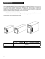
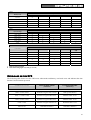
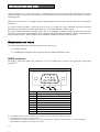
UNINTERRUPTIBLE POWER SUPPLY
- ON LINE 700 VA ÷ 3000 VA
Manuale d’uso
User’s manual
Bedienungsanleitung
Manuel d’utilisateur
Manual de usuario
GB
USER’S MANUAL
GB
37
INTRODUCTION
Thanks you for choosing our product.
Our manufacturer are renowned specialists in the development and production of uninterruptible power supplies
(UPS). The UPS in this range are high quality products, designed and built with care in order to give you the best
performance.
This equipment can be installed by anyone, subject to CAREFULLY AND THOROUGHLY READING
THIS MANUAL.
The manual contains detailed instructions on how to use and install the UPS.
For information on using and getting the best performance from your UPS, this manual should be kept
safely in the vicinity of the UPS and CONSULTED BEFORE TAKING ANY ACTION ON THE UPS.
© Reproduction of any part of this manual, including partial, is strictly prohibited without the prior consent of the manufacturer.
For the purpose of improving it, the manufacturer reserves the right to modify the product described herein at any time and without notice.
Microsoft, Windows, and the Windows logo are trademarks, or registered trademarks of Microsoft Corporation in the United States
and/or other countries.
38
CONTENTS
PRESENTATION
VIEW OF THE UPS
40
41
Front Views
41
Rear Views
42
VIEW OF LED INDICATOR PANEL
44
INSTALLATION AND USE
45
OPENING THE PACKAGING AND CHECKING THE CONTENTS
45
CONNECTIONS AND SWITCHING ON FOR THE FIRST TIME
46
Connection to the Net/Tel protection device
46
SWITCHING ON FROM MAINS POWER
46
SWITCHING ON FROM BATTERY
47
SWITCHING OFF THE UPS
47
LED INDICATOR PANEL
48
OVERLOADS ON THE UPS
49
COMMUNICATION PORTS
50
RS232 serial port
50
Communication Slot
51
SOFTWARE
51
Monitoring and control software
51
Configuration Software
51
UPS CONFIGURATION
ALARMS AND INDICATORS
52
53
UPS STATUS REPORTS TABLE
53
UPS FAILURE REPORTS TABLE
54
PROBLEM SOLVING
55
TECHNICAL SPECIFICATIONS
56
39
PRESENTATION
The new Dialog Plus family of UPS has been designed to offer versatility and reliability.
They use ON LINE technology, which means that the AC power for the load is converted to DC and then back
to AC again to ensure a perfectly sinusoidal output, the frequency and voltage of which are established by
microprocessor digital control and are independent of the input power source. This family of UPS has an
automatic by-pass device that switches the load to mains power in the event of overvoltages or any other power
problems to guarantee continuous power supply even in critical conditions.
This family of UPS is available in two versions:
Standard: with batteries inside of the UPS
ER:without batteries inside, but including a powerful batterycharger (max 8A). This series must be
combined with an external battery box, so it is indicated for long autonomy time.
The figures below show the various product versions:
Nominal power
Output nominal
voltage
Dimensions HxWxD
Weight
40
Dialog Plus
70
Dialog Plus
100/100ER
Dialog Plus
150
Dialog Plus
200/200ER
Dialog Plus
300/300ER
[VA]
[Vac]
700
1000
1500
2000
3000
[mm]
[Kg]
231x158x400
12
340x192x460
34/14
340x192x460
35/14
220/230/240
231x158x400
14/8
231x158x500
19
PRESENTATION
VIEW OF THE UPS
Front Views
Models: 700-1000-1500VA
Models: 2000-3000VA
1. LED indicator panel
2. ON button
3. OFF button
41
PRESENTATION
Rear Views
Dialog Plus 70
1
Dialog Plus 100 / 100 ER / 150
7
1
7
8
2
2
3
6
3
4
4
5
5
6
Dialog Plus 200
1
7
8
2
6
4
5
42
3
PRESENTATION
Dialog Plus 200 ER
1
Dialog Plus 300 / 300 ER
7
1
7
8
8
9
2
2
6
10
6
3
4
5
3
4
5
1.
2.
3.
4.
5.
RS232 serial communication port
Cooling fans
Telephone/modem protection
Input thermal protection
IEC mains input plug
6.
7.
8.
9.
10.
IEC output sockets (max 10A)
Communication expansion slot
Battery expansion connector
IEC 16A output socket
Output socket fuse boxes
43
PRESENTATION
VIEW OF LED INDICATOR PANEL
1
2
3
4
5
1
Load level indicator
2
Battery level indicator
3
Mains mode indicator
4
Battery mode indicator / Battery low indicator
5
Battery failure indicator
6
Load powered by bypass indicator
7
“Fault/Stand-by” indicator
44
6
7
INSTALLATION AND USE
OPENING THE PACKAGING AND CHECKING THE CONTENTS
The first thing to do after opening the packaging is to check the contents
The packaging should contain the following:
UPS
RS232 serial cable
IEC 10A(or 16A) Power cord
IEC 16A Power cord set (only for model
3000VA)
2 IEC 10A connection cables
User manual + CD-ROM with software
User's
manual
45
INSTALLATION AND USE
This chapter describes the operations to be carried out to prepare the UPS.
WARNING: the instructions below should be followed scrupulously for your personal safety and that of the
product.
BEFORE CARRYING OUT THE FOLLOWING SEQUENCE OF
OPERATIONS, MAKE SURE THAT THE UPS IS COMPLETELY SWITCHED
OFF AND IS NOT CONNECTED TO THE MAINS OR TO ANY LOAD.
CONNECTIONS AND SWITCHING ON FOR THE FIRST TIME
1) Connect the power cable supplied with the UPS to the IEC input socket.
2) Connect the UPS power cable to mains power supply.
3) After a few moments the UPS will be activated, a beep will be emitted and the “Fault/Stand-by” LED
will light. The UPS is now in the stand-by state: this means that the UPS is in a minimum consumption
condition. The microcontroller is powered and carries out supervision tasks and autodiagnostics; the
batteries are charging; the outputs are disconnected; the cooling fans are operating; everything is ready for
the UPS to be started up.
4) Connect the load/s to be powered to the sockets on the rear of the UPS using the IEC-IEC cables supplied
or a cable with maximum length of 10 meters.
N.B.: do not connect any loads that absorb more than 10A to the 10A IEC sockets. These loads should be
connected exclusively to the 16A IEC socket when this is available.
Connection to the Net/Tel protection device
A telephone/modem or network cable can be connected to the modular RJ-45/RJ11 connectors located on
the rear of the UPS that protect against overvoltages. A telephone extension cable is required for this type of
connection.
N.B.: The connection is optional. The Net/Tel protection is active even when the UPS is turned off or
disconnected from mains power.
Warning: The device that protects against overvoltage on the telephone line may not work if it is not
installed correctly. Ensure that the telephone wall cable is inserted in the connector marked “IN” and
that the cable of the unit to be protected (telephone, modem, network card, etc.) is inserted in the
connector marked “OUT”.
Warning: The overvoltage protection device is only for indoor use. Do not connect telephone wires
during a storm.
N.B.: The protection device limits the effects of an overvoltage but does not guarantee overall protection.
SWITCHING ON FROM MAINS POWER
1) Press the ON button for at least one second (until a beep sounds). Once it is released, all the LEDs come
on for 1 second and a beep sounds. The UPS then runs a short test on the battery voltage and mains power
status. In normal conditions, after this test, only the “mains” LED, load level and battery level indicators
stay lit (if different lights or audio signals appear/occur, consult the table in the “Alarms and Indicator”
Chapter for further details).
2) Switch on the loads connected to the UPS.
Only for the first time you switch on: after about 30 sec., check that the UPS is working correctly by:
1. Simulating a black-out by removing the mains power cable
2. The load must continue to receive power, the “battery mode” indicator should light up and the
UPS should beep every 4 seconds.
3. Reconnect the power cable. Normal mains power operation should be restored.
46
INSTALLATION AND USE
SWITCHING ON FROM BATTERY
1)
2)
When mains power is not available, press the ON button for about 1 second (until a beep sounds and
then release it). All the icons on the indicator panel light up for 1 second and a beep sounds. A test is run
on the batter voltage and, if all is normal, only the “Battery mode”, load level and battery level indicators
stay on accompanied by an intermittent beep.
Switch on all the loads connected to the UPS.
SWITCHING OFF THE UPS
When mains power is available, to switch off the UPS hold the OFF button down (for about 2 seconds) until
a beep sounds and then releases it. UPS returns to standby mode and only the “Fault/Standby” indicator
starts flashing.
When mains power is not available and time function is not on, to switch off the UPS hold the OFF button
down (for about 2 seconds) until a beep sounds and then releases it. The buzzer sounds for 1 second and all
LEDs light till the power source is shutdown completely.
When mains power is not available and time function is on, to switch off the UPS hold the OFF button
down (for about 5 seconds) until the 2nd beep sounds and then releases it. The buzzer sounds for 1 second
and all LEDs light till the power source is shutdown completely.
ADDITIONAL FUNCTIONS PERFORMED ON THE FRONT PANEL
UPS in stand by mode
To cancel a software programmed shutdown(1) keep the “ON” key pressed down until the 2nd beep is
heard and then release immediately (approx. 5 sec), or keep the “OFF” key pressed down until a beep is
heard and then release immediately (approx. 2 sec).
UPS in mains power mode
To mute the intermittent alarm on the UPS during the final phase of a software scheduled shutdown,
hold the ON key down (for about 1 seconds) until a 1st beep sounds and then release it
To cancel a software programmed shutdown(1) keep the “ON” key pressed down until the 2nd beep is
heard and then release immediately (approx. 5 sec), or keep the “OFF” key pressed down until a beep is
heard and then release immediately (approx. 2 sec).
To run a battery test, hold the ON key down (for about 5 seconds) until the third beep is heard and
then release it. At this point the test starts. The LEDs flash cyclically on the display panel. Once the test
is completed, if the batteries are in good condition, the UPS will return to mains mode with the usual
indications, or, if the batteries are faulty or discharged, the “battery failure” light comes on accompanied
by a beep (consult the table in the Alarms and Indicator Chapter for further details)
To see the approximate input mains voltage value of the UPS on the battery indicator, press the ON
button for at least 10 seconds until the 4th beep sounds. Release the button and the battery level indicator
shows the normal battery voltage value.
UPS in battery mode
To mute the intermittent alarm that sounds when the UPS is in battery mode, hold the ON button
down (for about 1 second) until the 1st beep is heard and then release it.
N.B. the UPS cannot be muted if the batteries are running low (1 beep every second).
To cancel a software programmed shutdown(1), hold the ON button down (for about 2 seconds) until
the 2nd beep is heard and then release it.
(1)
For more details on the functions that can be activated via software, consult the software manual on the CD-Rom
provided.
47
INSTALLATION AND USE
LED INDICATOR PANEL
This chapter gives a detailed description of all LED indicator panel.
ICON
STATUS
DESCRIPTION
Red / Steady
Indicates an fault
Red /
Flashing
The UPS is in stand-by mode
Green / Steady
The UPS is operating on mains power
Green / Flashing
The UPS is operating off the bypass
The voltage input is out of the accepted range
Green / Steady
The UPS is operating in battery mode and will beep at regular
intervals.
Green / Flashing
When operating off battery power, the UPS signals that it is about to
switch off due to end of discharge. In this state, it beeps at regular
intervals of 1 sec. (see Tab. 1)
Red / Steady
Indicates battery failure
Yellow / Steady
The loads connected to the UPS are powered by the bypass
Represents the estimated percentage of battery charge by 5 LEDs
(see table 2)
Green / Active
Hold the ON button down for at least 10 seconds to show the input
voltage value (see table 3)
Green – Red /
Active
Indicates the % of load applied to the UPS in relation to the nominal
value. the last icon indicates overload (see table 4)
Tab. 1
●
♦
48
Battery status
LED - battery working -
Normal
●
Low
♦
LED with steady light on
LED with flashing light on (1 flash per second)
INSTALLATION AND USE
Table 2
Battery level
1
2
Battery LED bar
3
4
5
0%~20%
●
20%~40%
●
●
40%~60%
●
●
●
60%~80%
●
●
●
●
80%~100%
●
●
●
●
●
1
2
Battery LED bar
3
4
5
Table 3
Input Voltage
190V~200V
●
200V~230V
●
●
230V~250V
●
●
●
250V~260V
●
●
●
●
>260V
●
●
●
●
●
100
!
Tab. 4
Load LED bar
Load level
25
50
75
0~5%
●
5~25%
●
25%~50%
●
●
50%~75%
●
●
●
75%~102%
●
●
●
●
>102%
●
●
●
●
●
LED on with steady light
♦ LED with flashing light on (1 flash per second)
OVERLOADS ON THE UPS
The following table shows how the UPS reacts when mains and battery overloads occur and indicates the time
that the UPS will remain powered.
OVERLOAD LEVEL
LOAD POWER TIMES
(off mains)
LOAD POWER TIME
(off battery)
102% < Load ≤ 109%
Switches to bypass after 30 min
Shutdown after 30 min (if battery
back up time allows)
110% <= Load ≤ 130%
Switches to bypass after 30 sec
Shutdown after 30 sec
130% < Load ≤ 150%
Switches to bypass after 10 sec
Shutdown after 10 sec
Load > 150%
Switches to bypass after 0.5 sec
Shutdown after 0.5 sec
Short circuit
Immediate shutdown
Immediate shutdown
49
INSTALLATION AND USE
After switching over to the bypass due to overloading, the UPS powers the loads off mains power and a
continuous alarm will sound. By reducing the load within the 102% threshold, the UPS returns to normal
operating mode.
When the overload level is too high, the input thermal protection is activated and the UPS will be completely
shutdown.
To restore normal operation, reduce the load so that it is within the 102% threshold and restore thermal
protection by pressing the relevant button on the rear of the UPS and then switch on again.
To restore normal operation following failure due to overloading (continuous beep and load not powered),
reduce the load so that it falls within the 102% threshold. Hold the OFF button down until the continuous beep
stops and then release it. Wait until the UPS is completely shutdown and then switch on again.
COMMUNICATION PORTS
The UPS has the following communication ports (see UPS views):
RS232 serial port
COMMUNICATION SLOTS: expansion slots for additional interface cards
RS232 serial port
The RS232 serial port allows the connection of a PC (COM port) by means of a pin-to-pin serial cable
(provided(1)).
RS232 CONNECTOR
6 7 8 9
1 2 3 4 5
PIN No.
1
2
3
4
5
6
7
8
9
(1)
(2)
(3)
50
SIGNAL
Contact closed: UPS failure/Bypass/Alarm (2)
TXD
RXD/SD (remote shutdown) (3)
GND
+12Vdc interface power input
PNP Signal
Contact closed: battery low pre-alarm (2)
Contact closed: battery mode (2)
If a different cable is used, it should be of the pin-to-pin type with a max. length of 3 metres.
Optoisolated contact max. +35Vdc / 15mA.
SD: With UPS in operation from battery, the UPS will perform a complete shutdown when +5~15Vdc is applied
(between PIN 3 and PIN 5) for at least 20 seconds.
INSTALLATION AND USE
Communication Slot
All UPS come with an expansion slot for optional communication boards so that the unit is compatible with the
main communication standards.
Some examples:
• Serial port duplexer
• Ethernet network agent with TCP/IP, HTTP and SNMP protocols
• RS232 + RS485 port with JBUS / MODBUS protocol
For more details on the options available, visit the manufacturer’s web site.
SOFTWARE
The CD-Rom provided includes two software programmes that allow the user to perform UPS monitoring,
control and configuration operations.
Monitoring and control software
The Powershield 2 software ensures efficient and intuitive UPS management, by displaying all the most
important information such as input voltage, applied load, battery capacity, etc.
It can also automatically execute programmed shutdown/start-up operations, shutdown of the O.S., sending of emails, sms and network messages when specific user-selected events occur.
Installation Operations:
•
•
•
•
Connect the UPS RS232 communication port to a COM port on the PC using the serial cable provided.
Insert the CD-Rom and select the operating system required.
Follow the installation instructions. .
For more detailed information on the installation and use of the software, refer to the software manual in the
Manuals folder on the CD-Rom provided.
Visit the manufacturer’s web site to check whether a more recent version of the software is available.
Configuration Software
UPSTools software allows the user to configure the UPS and provides a full view of the system parameters and
status through the RS232 serial port.
Refer to the paragraph UPS Configuration for a list of the possible configurations available.
Installation Operations:
• Connect the UPS RS232 communication port to the COM port on the PC using the serial cable provided.
• Follow the installation instructions given in the software manual in the UPSTools folder on the CD-Rom
provided.
Visit the manufacturer’s web site to check whether a more recent version of the software is available.
51
INSTALLATION AND USE
UPS CONFIGURATION
The following table lists all the possible configurations available so as to best adapt the UPS to user
requirements. The configuration may be modified only by using the configuration software provided
(UPSTools).
52
FUNCTION
DESCRIPTION
PREDEFINED
Automatic Restart
Automatic restart when
mains power returns
Enabled.
Battery low alarm
Remaining battery charge
level setting for the
battery low alarm
3 min.
Output frequency
Allows the user to select
the output frequency.
50Hz
Output voltage
Allows the user to select
the output voltage
230 Vac
Bypass voltage
threshold
Selects the voltage range
accepted for switching
over to bypass
Low: 180V
High: 264V
Battery capacity
Allow the user to set the
capacity of battery
POSSIBLE CONFIGURATIONS
• Disabled
• Enabled
1 - 99 in steps of 1 minute
• 50Hz
• 60Hz
• Auto (depending on the UPS input frequency
it will operate at 50 or 60 Hz)
• 220 Vac
• 230 Vac
• 240 Vac
Low:180 ÷ 200 in steps of 1V
High: 250 ÷ 264 in steps of 1V
The user must set the capacity of battery if the
Standard: 7.2Ah
actual capacity is different from the default
ER:
65Ah
value.
ALARMS AND INDICATORS
UPS
STATUS REPORTS TABLE
The following table describes the light and audio indicators that appear/sound during normal UPS operation.
Load level
Battery level
UPS Status
1
2
3
4
5
1
2
3
4
5
Mains
LED
Battery
LED
Bypass
LED
Battery
failure
LED
Bypass
Load level
Battery level
♦
Line
Load level
Battery level
●
Battery
normal
Battery
Load level
Test
phase
Test over:
●
●
1 beep
every 4s
♦
1 beep per
sec.
♦ (cyclically)
Load level
Battery level
If the
battery <
test
voltage
During
countdown
of shutdown
●
Battery level
Battery
low
During
countdown
of auto
restart
Audio
Alarm
♦
Standby
Battery test
Failure/
Fault
LED
6 beeps
●
Mains
normal
●
♦
Mains
abnormal
♦
♦
Line
mode
●
Load level
Battery
mode
(2 per
second)
♦
Battery level
♦
♦
1 beep
every 4s
(During
the final
phase of
the
shutdown)
LED on with steady light
♦ LED on with flashing light (1 flash per second)
53
ALARMS AND INDICATORS
UPS
FAILURE REPORTS TABLE
The following table describes the light and audio signals that appear/sound to indicate a fault.
Load level
Battery level
UPS Status
1 2 3 4 5 1
2
3
4
5
Alarm phase
Mains
overload
Mains
LED
Battery
LED
Bypass
LED
Battery
failure
LED
Failure/
Fault
LED
2 beeps
per sec.
●
Switch over
to bypass
due to
overload
●
Alarm phase
●
●
●
●
●
Battery level
♦
●
●
●
●
Battery level
●
●
●
Failure
Capacitor bank voltage fault
Load level
Output short circuit
Load level
●
Inverter fault
Load level
●
Overheating fault
Load level
●
●
●
♦
Bypass
●
♦ ♦ ♦ ♦ ♦
♦
●
continuo
us beep
●
continuo
us beep
●
continuo
us beep
●
continuo
us beep
●
♦
♦
●
●
Load level
Battery
charge fault
4 long
beeps at
1-second
intervals
●
Bypass
Line
●
Standby
Fan fault
Load level
Input Relay fault
Load level
●
LED on with steady light
♦ LED on with flashing light (1 flash per second).
54
continuo
us beep
●
Standby
●
●
Load level
Line
continuo
us beep
2 beeps
per
second
●
Battery
overload
Overloaded
Battery
fault
Audio
Alarm
●
●
♦
●
♦
●
1 beep
per
second
●
1 beep
per
second
●
Continuo
us beep
PROBLEM SOLVING
Very often incorrect UPS operation is not caused by a fault but by common problems, difficulties or
carelessness.
The table below gives some useful information to help the user solve the most frequent problems.
PROBLEM
POSSIBLE CAUSE
THE POWER CABLE IS NOT
CONNECTED
THE DISPLAY PANEL
DOES NOT LIGHT UP
THE PANEL IS ON BUT
THE LOAD IS NOT
POWERED
THE UPS IS IN BATTERY
MODE EVEN THOUGH
MAINS POWER IS
AVAILABLE
Check that the power cable is connected correctly.
NO MAINS POWER (BLACK- Check that there is voltage in the socket to which the
OUT)
UPS is connected (try with a table lamp)
INPUT THERMAL
PROTECTION IS ACTIVE
Reset the protection by pressing the button on the rear
of the UPS (CIRCUIT BREAKER).
N.B.: Check that there is no UPS output overload.
UPS IN STANDBY MODE
Press the ON button on the front panel to power the
loads.
THE LOAD IS NOT
CONNECTED
Check the connection to the load.
INPUT THERMAL
PROTECTION ACTIVE
Reset the protection by pressing the button on the rear
of the UPS (CIRCUIT BREAKER).
N.B.: Check that there is no UPS output overload.
THE INPUT VOLTAGE IS
OUTSIDE THE ACCEPTED
VALUES FOR OPERATION
OFF MAINS POWER
Mains power problem. Wait until the input voltage
returns to acceptable limits; the UPS will automatically
return to mains power mode.
A CONTINUOUS BEEP
SOUNDS AND THE LOAD
INDICATOR IS ALL LIT UP
THE LOAD CONNECTED TO
THE UPS IS TOO HIGH
“BATTERY FAILURE”
APPEARS ON THE
DISPLAY
THE BATTERIES MUST BE
REPLACED
A CONTINUOUS BEEP
SOUNDS AND THE LED
PANEL SHOWS ONE OF
THE INDICATIONS LISTED
IN THE “FAULTS TABLE”
SOLUTION
Reduce the load so that it falls within the 102%
threshold.
Contact the Technical Support centre
A FAULT HAS BEEN FOUND
Disconnect all the loads and reconnect them one at a
ON ONE OR MORE LOADS
time to identify the faulty load.
POWERED BY THE UPS
A MALFUNCTION HAS
OCCURRED
If possible disconnect the load, switch the UPS off and
on again. If the problem remains, call the Technical
Support centre.
55
3-
TECHNICAL SPECIFICATIONS
MODELS
INPUT
Nominal voltage
Transfer Voltage Range
- low line transfer
-Low line comeback
-High line transfer
-High line comeback
Nominal frequency
Nominal current
Power factor
Input protection
BYPASS
Accepted voltage range for switch over
Accepted frequency range for switch over
Time taken for switch over
BATTERY
N° batteries / V / Ah
Recharge time
OUTPUT
Nominal voltage
Static variation (4)
Dynamic variation (5)
Wave form
Voltage distortion @ linear load
Voltage distortion @ distorting load (3)
Frequency (6)
Synchronisation range
Current crest factor
Nominal power (3)
Nominal power
OTHER VALUES
Current leakage to ground
AC/AC efficiency
Ambient temperature (7)
Humidity
Protections
Dialog Plus 70
[Vac]
56
700
490
[mA]
---
220 / 230 / 240
1.5%
≤ 5% in 20 msec
Sinusoidal
≤ 3%
≤ 6%
50 – 60 Hz ± 0.2Hz
46-54Hz / 56-64Hz
3:1
1000
700
≤ 1.2
86%
[mm]
[Kg]
3 / 12 / 7.2
4 h to 80% of full charge
[Vac]
[°C]
6.2
Selected frequency ±5 %
Typically: 2 - Maximum: 4
2 / 12 / 7.2
[VA]
[W]
Based on load percentage
100-80% =160 ± 5
80-70% = 140 ± 5
70-60%= 120 ± 5
60-0%= 110 ± 5
170 ± 5
300 ± 5
285 ± 5
50 / 60
5
≥ 0.97
7A thermal breaker
180 - 264
[msec]
Safety certifications
EMC Compliance
Noise
Dimensions H x W x D
Weight
3.8
[Va
c]
[h]
Dialog Plus 100 ER
220 / 230 / 240
[load %]
[Vac]
[Vac]
[Vac]
[Vac]
[Hz]
[A]
Dialog Plus 100
88%
0 – 40
< 90% non condensing
Excessive battery discharge - overcurrent – short circuit –
overvoltage - undervoltage - thermal
EN62040-1-1 and EEC 73 / 23, 93/68 specifications
EN 50091 - 2 cl. B and EEC 89/336, 92/31, 93/68 specifications
12
< 45 dB(A) at 1 Mt.
231 x 158x 400
14
8
TECHNICAL SPECIFICATIONS
MODELS
INPUT
Nominal Voltage
Transfer Voltage Range
-Low line transfer
-Low line comeback
-High line transfer
-High line comeback
Nominal frequency
Nominal current
Power factor
Input protection
BYPASS
Accepted voltage range for switch over
Accepted frequency range for switch over
Time taken for switch over
Dialog Plus 150
[Vac]
Dialog Plus 200 ER
220 / 230 / 240
[load %]
[Vac]
Based on load percentage
100-80% =160 ± 5
80-70% = 140 ± 5
70-60%= 120 ± 5
60-0%= 110 ± 5
170 ± 5
300 ± 5
285 ± 5
50 / 60
[Vac]
[Vac]
[Vac]
[Hz]
[A]
Dialog Plus 200
7.2
10A thermal breaker
[Vac]
10
≥ 0.97
12A thermal breaker
13.4
16A thermal breaker
180 – 264
Selected frequency ±5 %
Typically: 2 - Maximum: 4
[msec]
BATTERY
N° batteries / V / Ah
Recharge time
OUTPUT
Nominal voltage
Static variation (4)
Dynamic variation (5)
Wave form
Voltage distortion @ linear load
Voltage distortion @ distorting load (3)
Frequency (6)
Synchronisation range
Current crest factor
Nominal power (3)
Nominal power
OTHER VALUES
Current leakage to ground
AC/AC efficiency
Ambient temperature (7)
Humidity
Protections
4 / 12 / 7.2
[h]
[Vac]
[VA]
[W]
[mA]
[°C]
Safety certifications
EMC compliance
Noise
Dimensions H x W x D
Weight
[mm]
[Kg]
8 / 12 / 7.2
4 h to 80% of full charge
1500
1050
---
220 / 230 / 240
1.5%
≤ 5% in 20 msec
Sinusoidal
≤ 3%
≤ 6%
50 ± 0.2Hz autosense
46-54Hz
3:1
2000
1400
≤ 1.2
88%
0 – 40
< 90% non condensing
Excessive battery discharge - overcurrent – short circuit –
overvoltage - undervoltage - thermal
EN62040-1-1 and EEC 73 / 23, 93/68 specifications
EN 50091 - 2 cl. B and EEC 89/336, 92/31, 93/68 specifications
231 x 158x 500
19
< 45 dB(A) at 1 Mt.
340 x 192 x 460
34
14
57
TECHNICAL SPECIFICATIONS
MODELS
INPUT
Nominal voltage
Transfer Voltage Range
-Low line transfer
-Low line comeback
-High line transfer
-High line comeback
Nominal frequency
Nominal current
Power factor
Input protection
BYPASS
Accepted voltage range for switch over
Accepted frequency range for switch over
Time taken for switch over
BATTERY
N° batteries / V / Ah
Recharge time
OUTPUT
Nominal voltage
Static variation (4)
Dynamic variation (5)
Wave form
Voltage distortion at linear load
Voltage distortion at distorting load (3)
Frequency (6)
Synchronisation range
Current crest factor
Nominal power (3)
Nominal power
OTHER VALUES
Current leakage to ground
AC/AC efficiency
Ambient temperature (7)
Humidity
Protection
Safety certifications
EMC compliance
Hold-up time
Noise
Dimensions H x W x D
Weight
58
Dialog Plus 300
[Vac]
220 / 230 / 240
[load %]
[Vac]
[Vac]
[Vac]
[Vac]
[Hz]
[A]
Dialog Plus 300 ER
Based on load percentage
100-80% =160 ± 5
80-70% = 140 ± 5
70-60%= 120 ± 5
60-0%= 110 ± 5
170 ± 5
300 ± 5
285 ± 5
50 / 60
14.4
16
≥ 0.97
16A thermal Breaker
[Vac]
[msec]
[h]
[Vac]
[VA]
[W]
[mA]
[°C]
[msec]
[mm]
[Kg]
180 - 264
Selected frequency ±5 %
Typically: 2 - Maximum: 4
8 / 12 / 7.2
--
4 h to 80% of full charge
--
220 / 230 / 240
1.5%
≤ 5% in 20 ms
Sinusoidal
≤ 3%
≤ 6%
50 ± 0.2Hz autosense
46-54Hz
3:1
3000
2100
≤ 1.2
88%
0 – 40
< 90% non condensing
Excessive discharge of batteries – overcurrent – short circuit –
overvoltage – undervoltage – thermal
EN 62040-1-1 and EEC 73 / 23, 93/68 specifications
EN 50091 - 2 cl. B and EEC 89/336, 92/31, 93/68 specifications
≥ 40
< 45 dB(A) at 1 Mt.
340 x 192 x 460
35
14
TECHNICAL SPECIFICATIONS
(1)
at nominal load, minimum voltage of 164 Vac, battery charging
(2)
at nominal load, nominal voltage of 230Vac, battery charging
(3)
Second appendix M5 of the EN50091-1-1 specifications
(4)
Mains/Battery at load: 0% -100%
(5)
at Mains / battery / mains at resistive load: 0% / 100% / 0%
(6)
If the mains frequency falls within ± 5% of the selected value, the UPS is synchronised with mains voltage. If the
frequency is outside the accepted values or if the UPS is in battery mode, the selected frequency is adopted +0.1%.
(7)
20 - 25 °C to ensure a longer battery life.
59
UPS MANUFACTURING s.r.l.
I – 37048 S.Pietro di Legnago (VR)
Italy – Viale Europa, 7 – ZAI
Tel. +39 0442 635811 – Fax +39 0442 629098
www.riello-ups.com - [email protected]
0MNUOC1RUB