1
Quick Programming Setup
ProSYS Version 7.xx
For detailed information please refer to the full ProSYS Installer Manual
provided on our website: www.riscogroup.com
Table of Contents
Introduction......................................................................................................................................3
I. Suitable Locations........................................................................................................................3
II. Installing Hardware (Devices).....................................................................................................3
1. BUS Connection..................................................................................................................... 3
1.1 Setting BUS Accessory ID Numbers ..........................................................................4
2. Setting Zone Inputs Connection........................................................................................... 5
2.1 Connection on the main unit (ProSYS 7), G3 zone expanders (ProSYS EZ8G3,
EZ16G3) or Inputs on iWISE BUS................................................................................5
2.2 Connection on the main unit (ProSYS 5), Zone expanders (ProSYS EZ8, EZ16)....6
3. Wiring Auxiliary Devices (Sensors)...................................................................................... 6
4. Wiring Internal Bell ................................................................................................................ 6
5. Bell Tamper Wiring (Terminal Bell TMP) .............................................................................. 6
6. Wiring UO1 to Activate Any External Stand-alone Siren .................................................... 7
7. Wiring Important BUS Accessories...................................................................................... 7
7.1 Wiring the Voice Module..............................................................................................7
7.2 ProSound - BUS Siren Connection.............................................................................8
7.3 Wiring the GSM.............................................................................................................8
7.4 Wiring BUS Detectors .................................................................................................9
III. Programming the System ........................................................................................................10
Power Up and Enter Installer Mode........................................................................................ 10
Identifying the Connected Devices (including BUS Detectors) ........................................... 11
Automatic Settings ............................................................................................................11
Bus Test ..............................................................................................................................11
Programming: SYSTEM........................................................................................................... 11
SYSTEM - Timers ...............................................................................................................11
SYSTEM - Controls ............................................................................................................11
SYSTEM - Set Clock ...........................................................................................................12
Programming: Wireless ZONES ............................................................................................. 12
ZONES - Wireless Calibration ...........................................................................................12
ZONES - Wireless Zone Allocation ...................................................................................12
ZONES - Wireless Communication Test...........................................................................13
Programming: ZONES Wired & Wireless (Attributes)........................................................... 13
PARTITIONS .......................................................................................................................13
GROUP SETS......................................................................................................................13
ZONE TYPE.........................................................................................................................13
ZONE SOUND .....................................................................................................................13
ZONE TERMINATION .........................................................................................................14
ZONE RESPONSE ..............................................................................................................14
ZONE LABELS....................................................................................................................14
Programming BUS Detectors.................................................................................................. 14
Programming BUS detectors on the Main BUS...............................................................14
Programming BUS Detectors on a BUS Zone Expander ................................................15
Programming the Input on the iWISE BUS Detector .......................................................16
Programming: Dialer (For PSTN Dialing)............................................................................... 17
DIALER - Link-Up ...............................................................................................................17
DIALER - Accounts ............................................................................................................17
DIALER - Communication Format ....................................................................................17
DIALER - Control ................................................................................................................18
DIALER - Auto Codes.........................................................................................................18
DIALER - Follow Me ...........................................................................................................18
Programming: PROG OUTPUTS............................................................................................. 18
PROG OUTPUTS - Define ..................................................................................................18
Codes........................................................................................................................................ 19
System Backup ........................................................................................................................ 19
Exiting Programming Mode .................................................................................................... 19
Installer Programming Menu Maps ..............................................................................................20
Technical Specifications...............................................................................................................26
2
ProSYS Quick Programming Setup
Introduction
This simple setup procedure guide covers all common ProSYS programming steps (based on
factory default settings) required in order to have a working system.
I. Suitable Locations
Decide where to position your ProSYS control panel. A central location is often the best place,
making wiring to expanders and accessories easier. It is advisable to prepare a plan of
expander/accessory physical locations in advance to the installation, as this will determine which
type of expander is required at each location.
The control panel location should be:
•
In a dry place near an AC power supply (switched off).
•
With a good earth connection.
•
With access to the customer’s phone lines.
•
With access to the routing of cables for the system from detection devices.
Warning:
If connecting remote power supplies, do NOT connect the Red wire (+12v) between the Power Supply Unit and
ProSYS.
II. Installing Hardware (Devices)
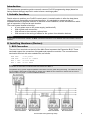
1. BUS Connection
The set of four terminals on the left of the Main Panel represent the Expansion BUS. These
terminals support the connection of keypads and expansion modules. The connections are
terminal-to-terminal with color-coded wires, as follows:
AUX
COM
BUS
BUS
RED
BLK
1 YEL
1 GRN
+12V power
Black 0V common
Yellow DATA
Green DATA
Note:
For BUS 2 the terminals are identical but with reference to BUS 2.
The parallel wiring system supports parallel connections from any point along the wiring. The maximum wire
run permitted is 300 meters (1000 feet) for all legs of the BUS for long cable runs. Please use the correct
cable as stated on page 1-3 of the Installation Manual.
ProSYS Quick Programming Setup
3
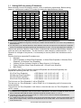
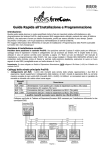
1.1 Setting BUS Accessory ID Numbers
Each accessory has its ID category number, which is defined by dipswitches. Before setting
power on, define each module’s ID number by setting the dipswitches as follows:
ID
01
02
03
04
05
06
07
08
09
10
11
12
13
14
15
16
1
OFF
ON
OFF
ON
OFF
ON
OFF
ON
OFF
ON
OFF
ON
OFF
ON
OFF
ON
Dipswitches
2
3
4
OFF OFF OFF
OFF OFF OFF
ON
OFF OFF
ON
OFF OFF
OFF ON
OFF
OFF ON
OFF
ON
ON
OFF
ON
ON
OFF
OFF OFF ON
OFF OFF ON
ON
OFF ON
ON
OFF ON
OFF ON
ON
OFF ON
ON
ON
ON
ON
ON
ON
ON
5
OFF
OFF
OFF
OFF
OFF
OFF
OFF
OFF
OFF
OFF
OFF
OFF
OFF
OFF
OFF
OFF
ID
17
18
19
20
21
22
23
24
25
26
27
28
29
30
31
32
1
OFF
ON
OFF
ON
OFF
ON
OFF
ON
OFF
ON
OFF
ON
OFF
ON
OFF
ON
Dipswitches
2
3
4
OFF OFF OFF
OFF OFF OFF
ON
OFF OFF
ON
OFF OFF
OFF ON
OFF
OFF ON
OFF
ON
ON
OFF
ON
ON
OFF
OFF OFF ON
OFF OFF ON
ON
OFF ON
ON
OFF ON
OFF ON
ON
OFF ON
ON
ON
ON
ON
ON
ON
ON
5
ON
ON
ON
ON
ON
ON
ON
ON
ON
ON
ON
ON
ON
ON
ON
ON
Notes:
1: Most accessories have 4 Dipswitches while the BUS Detectors have 5 Dipswitches
2: IDs 9-16 are available for keypads, proximity key readers and BUS Detectors. ID 17-32 is only available for
BUS Detectors.
3. You may have up to 128 BUS detectors. Each detector must have a unique ID on the BUS zone expander
that it is connected to, therefore each ID can be used twice or more - once on each BUS zone expander.
Devices are split into ‘Families’. Each ‘Family’ of devices has sequential identification numbers
which are set by the Dipswitches. The first module in each category is defined as ID= 1. If a
Dipswitch is changed on any device, it is necessary to remove power from that device and repower.
Families that have sequential ID numbers are:
•
Keypads
•
Zone Expanders (8 Wired Zone Expander, 16 Wired Zone Expander, 8 Wireless Zone
Expander, 16 Wireless Zone Expander)
•
Outputs (8 Open Collector Outputs, 4 Relay Outputs, X-10 Outputs)
•
Power Supplies (3Amp Power Supplies and 1.5 Amp Power Supplies)
•
BUS Zones
For example: Each Zone Expander (Hardwired Expander and Wireless Expander) has
sequential numbering such as 1,2,3,4 etc…
ID1 (First Zone Expander)
ID2 (Second Zone Expander)
ID3 (Third Zone Expander)
ID4 (Fourth Zone Expander)
= DIP Switch ‘1 off, 2 off, 3 off, 4 off’
= DIP Switch ‘1 on, 2 off, 3 off, 4 off’
= DIP Switch ‘1 off, 2 on, 3 off, 4 off’
= DIP Switch ‘1 on, 2 on, 3 off, 4 off’
= [↓↓↓↓]
= [↑↓↓↓]
= [↓↑↓↓]
= [↑↑↓↓]
The first zone on ‘Zone Expander’ 1 will be ZONE 09
The last zone on ‘Zone Expander’ 1 will be ZONE 16 or 24 (depending on 8/16 zones on the
zone expander).
The first zone on ‘Zone Expander’ 2 will follow on from the last zone on ‘Zone Expander’ 1. See
NOTE 1 below.
4
Notes:
1: On Wireless Zone Expanders, there are two banks of Dipswitches. One bank for ZONE ID number and one
bank for Wireless KEYFOB ID number. Wireless Keyfob ID numbers can be 1, 2, 3 or 4.
2: The main unit can support a maximum load of 1.4 Amp. If more current is required install additional
power supply modules (1.5 or 3 Amp).
3: On 3 AMP Supervised Power Supplies, there are two programmable outputs. These programmable outputs
belong to the ‘Output’ family. There are two Dipswitches on the 3 AMP PSU, one for the PSU ID and one
for the OUTPUT ID.
ProSYS Quick Programming Setup
Maximum number of Devices possible:
Total number of zone expanders
Outputs expanders
Keypads
Power Supply
ProSound Siren
ProSYS16
1x8
2
8
8
8
ProSYS40
4x8 or 2x16 or 2x8 + 1x16
4
12
8
8
ProSYS128
1x8 + 7x16
8
16
8
8
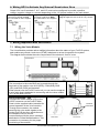
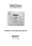
2. Setting Zone Inputs Connection
The following diagrams illustrate the various possible zone connections.
2.1 Connection on the main unit (ProSYS 7), G3 zone expanders (ProSYS
EZ8G3, EZ16G3) or Inputs on iWISE BUS
Note:
TEOL uses normally-closed (NC) contacts in a zone to distinguish between alarm, tamper condition and
fault/AM condition using 4.7 K +6.8 K + 12 K End-of-Line resistors.
Note:
The values in the diagram above refer to ProSYS version 7.xx.
ProSYS Quick Programming Setup
5
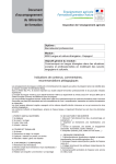
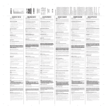
2.2 Connection on the main unit (ProSYS 5), Zone expanders (ProSYS EZ8,
EZ16)
NORMALLY CLOSED
ZONE CONFIGURATION
zone
com
NORMALLY OPEN ZONE
CONFIGURATION
zone
com
END OF LINE ZONE
(N.C CONTACT)
zone
com
END OF LINE ZONE
(N.O CONTACT)
zone
DETECTOR
2.2 K 2.2 K
ALARM
ALARM
ALARM
DETECTOR
DETECTOR
com
zone
2.2 K
2.2 K
ALARM
ALARM
DETECTOR
com
DOUBLE END OF LINE
ZONE CONFIGURATION
TAMPER
DETECTOR
Note:
The values in the diagram above refer to ProSYS version 5.xx and below.
3. Wiring Auxiliary Devices (Sensors)
Use the Auxiliary Power AUX (+) COM (-) terminals to power PIRs, glass-break detectors (4wire types), smoke detectors, audio switches, photoelectric systems and/or any device that
requires a 12V DC power supply.
The total power from the AUX terminals should not exceed 600mA.
Note:
If the auxiliary outputs are overloaded (exceed 600mA) and are shut down, you must disconnect all loads from
the outputs for a period of at least 10 seconds before you reconnect any load to the auxiliary outputs.
4. Wiring Internal Bell
The Bell/LS terminal provides power to the internal siren. When connecting an internal sounding
device, pay attention to the polarity.
It is important to position the BELL/LS Jumper (J3) correctly. The position varies depending on
the type of internal siren.
A maximum of 900 mA may be drawn from this terminal.
Note:
To avoid Bell Loop Trouble, if no connections are made to an internal siren, use a 2.2KΩ resistor in its place.
5. Bell Tamper Wiring (Terminal Bell TMP)
Connect the bell tamper to the BELL TMP and COM terminals on the Main Panel using 2.2KΩ
resistor in serial.
Important:
If you DO NOT use the terminal TMP BELL, remember to connect a 2.2KΩ resistor (Resistor colors: Red, Red,
Red) BELL between TMP and COM.
PROSYS MAIN PANEL
BELL
TMP
COM
2.2 K EOL
RESISTOR
BELL TAMPER
6
ProSYS Quick Programming Setup
6. Wiring UO1 to Activate Any External Stand-alone Siren
Output UO1 has 3 terminals C, N.C. and N.O. and can be configured to provide a positive
voltage, negative voltage or a contact depending on the J10 jumper located on the main board.
Positive (POS): When the J10
connector is placed on POS,
the C terminal on UO1 supplies
13.8V
Negative (NEG): When the J10
connector is placed on NEG,
the C terminal on UO1 supplies
COM
Single pin: If the J10 connector is placed
only on 1 pin, the UO1 acts as a dry contact.
7. Wiring Important BUS Accessories
7.1 Wiring the Voice Module
The Voice Module provides native audible information about the status of your ProSYS system,
and enables any remote, touch-tone (DTMF) telephone to act as a keypad for the system.
The diagram below shows the main components of the electronic form of voice:
Voice Connection – JP2
Connects the Voice module (JP2) to the
VOICE connector on the ProSYS Main
Panel via the supplied cable (essential for
normal operation of the Voice module).
Through this connector, the module
transmits the voice audio signals to the
central ProSYS who then sends them on
the telephone line for remote
communication with the phone numbers
dedicated to Follow Me destinations. This
connection is necessary for the proper
functioning of the module.
ProSYS Quick Programming Setup
Voice
Module
AUX COM
BUS
RED BLK YEL GRN
ProSYS
AUX COM
BUS
RED BLK YEL GRN
BUS Connection – JP1
The connection to the main BUS can be made through the
terminals of the module voice AUX (RED), COM (BLK), BUS
(YEL) and BUS (GRN) as illustrated.
When placed near the ProSYS main unit you can use the supplied
4-wire cable that is dedicated to connecting with the voice module
(JP1) to the BUS ProSYS
Identical
Connectors
7
7.2 ProSound - BUS Siren Connection
Connect the siren according to the diagram. Set the related Dipswitches for BUS mode
operation.
Dipswitch CONFIG 2 should be in ON position for ProSound BUS connection
Dipswitch CONFIG 4: Defines the siren sound rhythm (ON = Slow, Off = Fast)
Dipswitch ID1: 1-3: Set ID BUS Number. Up to 8 sirens can be connected to the ProSYS
Dipswitch ID1 4: Set different siren sound
Notes:
The PROX and TRBL outputs are deactivated in BUS mode configuration.
To protect the battery against deep discharge, the battery will automatically disconnect below 10.5 VDC.
The siren will not operate when a battery is not connected.
To
Battery
+
PS
BLK
RED
F
PROX
BUS
YEL GRN
R
TAM PER
INT EXT
SPEAKER
TAM PER
(To Int.
Tam per)
TRIG STROB
CST
1
M AN
AUX
RED
AUTO
LED
TRBL C +
ON
CC +
COM
BLK
POW ER
ON
2
3
1
4
2
3
4
ID1
CONFIG
LED2
7.3 Wiring the GSM
ProSYS Main
SET
GSM/GPRS Module
LINE
SET
PHONE
To telephone set
LINE
PHONE
To PSTN Line from
the Wall
Telephone cable to bring
the voice messages from
the ProSYS to the module
BUS GSM / GPRS
Important:
Do NOT make any connection to the RED Power terminal from the security panel.
8
ProSYS Quick Programming Setup
To Internal
Speaker
To
ProSYS
Panel
BUS
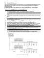
7.4
Wiring BUS Detectors
The ProSYS supports integration of BUS detectors. Up to 32 addressable BUS detectors can be
assigned to the main unit without the need to add any additional hardware zone expanders
(using virtual zones).
To assign more than 32 BUS detectors (up to 128) you need to add BUS Zone Expanders.
For full installation instructions refer to the instructions supplied with each BUS detector.
Connecting BUS Detectors to the ProSYS panel:
1.
Set the BUS detector ID number (1-32) using the detector's Dipswitches.
Note:
For WatchOUT, LuNAR, and WatchIN set the switch that defines the detector operation mode to BUS
mode.
2.
Wire the BUS terminals (RED), COM (BLK), BUS (YEL) and BUS (GRN) to the ProSYS
BUS.
Note:
For maximum operation stability, it is best NOT to exceed a total 300 meters (1000 feet) of wiring from
the BUS detector to the ProSYS panel.
Connecting BUS Detectors using a BUS Zone Expander:
1.
2.
3.
4.
Set the BUS Zone Expander ID number (1-8) using the Dipswitches SW1 1-3.
Using SW2 Dipswitches, set the number of zones this expander will support (8,16,24,32)
Wire the BUS Zone Expander terminals marked as TO PANEL to the ProSYS BUS.
Set the BUS detector ID number (1-32) using the detector's Dipswitches.
Note:
Do not repeat the same ID twice on the same BUS zone expander.
5.
Wire each detector's BUS terminals to the relevant BUS zone expander's terminals
marked as TO DEVICE.(see figure below)
Note:
For maximum operation stability, it is best NOT to exceed a total of:
•
300 meters (1000 feet) of wiring from the BUS Zone Expander to the ProSYS panel.
•
300 meters (1000 feet) of wiring from the BUS Zone Expander to the last BUS detector.
ProSYS Quick Programming Setup
9
III. Programming the System
Power Up and Enter Installer Mode
1.
Connect Mains power. The keypad displays "Partition 1".
2.
Press
3.
4.
If a Master/Manager code is required, press [1][2][3][4]
You are prompted for the Installer Code.
5.
[7][1] to go into the installer programming menu.
(Default Master Code).
For ProSYS16, press [0][1][1][6]
(Default Installer Code)
For ProSYS40, press [0][1][4][0]
(Default Installer Code)
For ProSYS128, press [0][1][2][8]
(Default Installer Code)
You are now in Installer Programming mode. Move to the section "Identifying the
connected devices" described below.
Quick Keys shown (in square brackets) can be pressed when at the ‘Main Menu’ instead
of using the Up/Down keys
Notes:
If required, you can default the panel to manufacturer's default settings as follows:
1. Fit J2 (the Default Jumper) across both pins in order to default.
2. Connect the Mains power. Wait until the keypad displays “To Install Press * ”.
3. Press * and enter the default installer code, depending on the ProSYS type. The system automatically
enters the automatic accessories settings process.
4. Remove J2 Default Jumper and place it back on one pin.
5. Move to the section "Identifying the connected devices" described below.
Navigating through the menus:
When navigating through the ProSYS menus, the following keys are used:
-
- to enter numeric values where required
- to scroll up or down through the menu options displayed
- Enter / Save (to move into the displayed menu or to save the data that
you have changed)
- to toggle displayed menu options from ‘N’ to ‘Y’ and vice-versa
- to go back / quit / don’t save
If you do not know where you are in the menu structure, press
main menu.
Entering Text Descriptions (Labels):
10
Key [1]
Key [2]
Key [4]
Key [5]
=
=
=
=
1ABCDEFGHIJKLM
2NOPQRSTUVWXYZ
1abcdefghijklm
2nopqrstuvwxyz
Key
= Move cursor Left
Key
= Move cursor Right
Key
= Save
ProSYS Quick Programming Setup
repeatedly to return to the
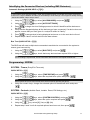
Identifying the Connected Devices (including BUS Detectors)
Automatic Settings (QUICK KEYS = [7][5])
Note:
In most cases, when entering Installer mode with the default jumper connected, the system will ‘assume’
that this is a ‘virgin’ installation and take you immediately to Auto Settings. If the keypad is already showing
“AUTO SETTINGS”, skip to step 3 below.
1.
Using the
/
keys, select [ACCESSORIES] and press
2.
Using the
/
keys, select [AUTO SETTINGS].
3.
to begin the Auto Settings process in which it identifies all the devices on
Press
the BUS.
Verify that the Keypad displays all the devices you have connected. If a device does not
appear, ensure that you have given it a unique ID within its “family”.
4.
5.
6.
.
to accept what is being displayed and move on to the next device found.
Press
Repeat steps 4 and 5 until all devices have been shown.
Bus Test (QUICK KEYS = [7][3])
The BUS test will send multiple test commands to each device connected to the system to
ensure good connectivity.
1.
2.
Using the
/
keys, select [BUS TEST] and press
Using the
/
keys, check that every device shown reports 99% or higher.
.
Note:
If a low reading is experienced, check connections with the device and repeat the BUS test.
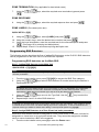
Programming: SYSTEM
SYSTEM - Timers (Entry/Exit Times etc)
QUICK KEYS = [1][1]
1.
Using the
/
keys, select [TIME DEFINE] and press
2.
Using the
/
keys, select the required timer option and press
.
.
Note:
Some options have more menu levels which are accessed by pressing the [#] key.
3.
Using the numeric keys, change the selected option to the desired value and press
.
SYSTEM - Controls (Audible Panic, Installer Reset, EN Settings, etc.)
QUICK KEYS = [1][2]
keys, select [SYSTEM CONTROL] and press
1.
Using the
/
2.
Using the
/
3.
Using the
4.
Repeat step 2 and 3 until all required options have been set, then press
keys, select the option required and press
.
.
key, select [Y] (Yes) or [N] (No)
ProSYS Quick Programming Setup
.
11
SYSTEM - Set Clock
QUICK KEYS = [1][3]
1.
Using the
/
keys, select [SET CLOCK] and press
2.
Using the
/
keys, select [SYSTEM TIME] and press
3.
Using the numeric keys, enter the current time and press
4.
5.
Using the
/
keys, select [SYSTEM DATE] and press
Using the numeric keys, enter the day (01 to 31).
.
.
.
.
6.
Using the
key, select the current month.
7.
Press the
button once to advance the cursor one position right.
8.
Using the numeric keys, enter the current year and press
.
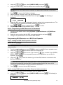
Programming: Wireless ZONES
ZONES - Wireless Calibration (Wireless Receiver background noise threshold setting)
QUICK KEYS = [2][9][5]
1.
Using the
/
keys, select [MAINTENANCE] and press
2.
Using the
/
select [WL CALIBRATE] and press
/
.
.
select the Wireless Receiver and press
.
3.
Using the
4.
Using the
5.
6.
.
After a short while, the measured background noise will be shown.
Add 10 to the displayed ‘NEW THOLD’ (New Threshold) by using the numeric keys and
press
key, choose [Y] (Yes) to ‘Re-Calibrate’ the Wireless Receiver and press
.
Explanation:
The Calibration measurement above shows the amount of background ‘noise’ that the receiver
can ‘hear’ on the same frequency as the RISCO wireless devices. This ‘noise’ could be
neighboring devices of another system or other devices operating on the same frequency
nearby. These are ‘unwanted’ signals that the ProSYS wireless receiver must be told ‘not to
listen to’.
The threshold (set above) is the absolute minimum signal strength needed to be heard from a
wireless device in order for the receiver to effectively ‘hear it’. This ‘threshold’ is set at ten above
the background ‘noise’ (recommended) making the receiver ignore the unwanted signals.
With this threshold set, the ProSYS receiver will only hear its own devices which are nearer and
have a signal strength greater that the threshold level set.
ZONES - Wireless Zone Allocation (Enrolling the wireless devices)
QUICK KEYS = [2][9][6]
1.
12
Using the
/
keys, select [MAINTENANCE] and press
/
keys, select [WL ZONE ALLOC] and press
.
.
2.
Using the
3.
Using the numeric keys, enter the desired zone number and press
4.
5.
/
keys, select [(RE)WRITE] and press
.
Using the
Depending on the wireless device enrolled, please do one of the following:
ProSYS Quick Programming Setup
.
)
)
)
6.
7.
For Wireless PIRs, Door Contacts, Flood Detectors, Shock Detectors - Close the
tamper
For Wireless Smoke Detectors, Fit the batteries and lid, then do nothing for 10-30
seconds
For Wireless PANIC Pendants, press the button(s) for 10 seconds (Cannot be
Supervised)
/
keys, select [SUPERVISED] or [NONE SUPERVISED] for this
Using the
wireless device.
Repeat steps 3 to 6 until all required wireless devices have been enrolled.
ZONES - Wireless Communication Test (Signal strength of the wireless devices)
QUICK KEYS = [2][9][7]
/
keys, select [MAINTENANCE] and press
1.
Using the
2.
3.
/
keys, select [WL COMM TEST] and press
Using the
Activate all wireless devices in turn.
4.
Using the
zone number.
/
.
.
keys, observe the signal strength received from each device
Note:
Make sure that the signal strengths are at least 10 units higher than the receiver threshold level.
Programming: ZONES Wired & Wireless (Attributes)
The bold sub headings below are ‘Main Menu’ headings.
key is pressed to move into the various sub menus.
The
To return to the ‘Main Menu’ headings at any time, press [*] repeatedly.
1.
Using the Up/Down keys, select [ONE BY ONE] and press
2.
Using the numeric keys, enter the desired zone number and press
.
.
PARTITIONS
3.
Using the numeric keys, select or deselect the relevant partitions to which this zone will
belong to and press
.
GROUP SETS
4.
Using the [A], [B], [C] or [D], keys, select the required group and press
.
ZONE TYPE
5.
Using the Up/Down keys, select the required zone type and press
.
ZONE SOUND
6.
Using the
/
keys, select the required zone sound option and press
.
Note:
This determines if the zone will ‘be silent’, ’cause Bell to activate’, ‘cause Buzzer to activate’, ‘cause Bell
and Buzzer to activate’, ‘create keypad bleep for chime’ etc… when the zone is opened/causes an alarm
condition.
‘Buzzer’ refers to the sound emitted from the Keypad(s).
ProSYS Quick Programming Setup
13
ZONE TERMINATION (Only applicable for hard wired zones)
7.
Using the
/
keys, select the required zone termination type and press
.
ZONE RESPONSE
8.
Using the
/
keys, select the required response time and press
.
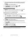
ZONE LABELS (Zone description text)
QUICK KEYS = [2][8]
9.
Using the
/
keys, select [LABEL] and press
.
.
10. Using the numeric keys, enter the desired zone number and press
11. Using the keys listed below, enter the required text for the zone description and press
. (See page 10 for entering text descriptions.)
12. Repeat steps 10 and 11 for all zones requiring description text.
Programming BUS Detectors
The following section describes the flow of adding BUS detectors to the ProSYS. BUS detectors
can be programmed to the main unit or to a BUS zone expander.
Programming BUS detectors on the Main BUS
Step 1: Adding BUS Detector to the Main Unit
QUICK KEYS = [7][1][9][5]:
Note:
If you have already performed Auto Settings skip to Step 2 below: Assign BUS Detectors to a Zone ID and
set basic parameters.
1.
From the main installer menu press [7][1][9][5] to access the BUS Zone category.
2.
/
Using the
Dipswitches (01-32)
keys select a BUS detector ID number as set by the detector's
Note:
The bottom line in the display shows "(0:yy) Type: None". In the 0:yy designation, the 0 represents
that the BUS detector is on the main unit and is not assigned to a BUS Zone Expander. The yy
represents the BUS detector ID number (up to 32) as set by the detector's DIP switches.
3.
4.
Using the
/
keys move to the Type field. Use the
detector's type.
Repeat steps 2 and 3 for other BUS detectors.
key to select the
Note:
If required you can add virtual zones to the system. Virtual zones are cost effective. They enable to use up
to 32 BUS Zones on the main unit without adding physical zone expanders. To add a Virtual BUS zone
expander select type VBZ08 or VBZ16 when adding a zone expander (Quick key [7][1][2]).
Step 2: Assign BUS Detectors to a Zone ID and set basic parameters
Each BUS zone detector should be assigned to a zone. BUS zones on the main unit can be
assigned to a virtual zone or to a physical wired zone. They cannot be assigned to wireless
zones or zones located on a BUS zone expander
1. From the main installer menu press [2] to enter the Zones menu.
14
ProSYS Quick Programming Setup
2.
3.
Using the
keys, select [ONE BY ONE] and press
/
Using the numeric keys, enter the desired zone number and press
.
.
Note:
You can select any zone number that is not defined on a Wireless Zone Expander or a BUS Zone
Expander.
4.
5.
Press
to access the Partitions category.
Define Partitions, Groups, Zone Type and Zone Sound.
6.
In the Termination category select BUS Zone and press
displayed:
Z:001
(0:yy)
. The following is
LINK TO:
TYPE:NONE
7.
Select the BUS zone number (designated by yy) to assign to the programmed zone. The
TYPE field will be updated automatically when selecting the zone.
8.
9.
Press
. Define a label and press
Repeat steps 3-8 for all required BUS zones.
to confirm.
Step 3: Programming the BUS Detectors Full Parameters
1.
2.
3.
From the main Installer menu select [2] Zones > [0] Miscellaneous > [3] BUS Zone
Parameters.
Select the zone number that the BUS zone was assigned to and press
.
Configure the parameters for the relevant BUS detector
Programming BUS Detectors on a BUS Zone Expander
Step 1: Adding the BUS Zone Expander to ProSYS
QUICK KEYS = [7][1][2]:
Note:
If you already performed Auto Settings skip to Step 2 below: Assign BUS Detectors to a Zone ID and set
basic parameters.
1.
From the main installer menu press [7][1][2] to enter the add BUS zone expander menu.
/
keys select a BUS Zone Expander ID.
2.
Using the
3.
/
keys move to Type. Use the
key to select a type (BZE08,
Using the
BZE16, BZE24 or BZE32 zone expander) based on the Dipswitches you set on the
.
expander. Press
4.
key, select the detector type of each BUS detector connected to this
Using the
BUS zone expander.
Note:
The bottom line in the display shows "(x:yy) Type: None" . In the x:yy designation, the x represents
the BUS Zone Expander ID number and the yy represents the BUS detector ID number that is
connected to the zone expander, as set by the detector's Dipswitches.
5.
Press
to move to the next BUS detectors.
Step 2: Assign BUS Detectors to a Zone ID and set basic parameters
1.
From the main installer menu press [2] to enter the Zones menu.
2.
Using the
displayed:
/
keys, select [ONE BY ONE] and press
. The following is
ZONE ONE BY ONE:
ZONE=001 (X:YY)
ProSYS Quick Programming Setup
15
3.
4.
Using the numeric keys, select a zone number whose designation (x:yy) is equivalent to
the one defined for the BUS detector. (The x represents the BUS Zone Expander ID
number and the yy represents the BUS detector ID number as set by the detector's ID
Dipswitches).
to access the Partitions category.
Press
Define Partitions, Groups, Zone Type and Zone Sound.
5.
In the Termination category select a BUS Zone and press
6.
7.
Press
. Define a label and press
Repeat steps 3-7 for all required BUS zones.
.
to confirm.
Step 3: Setting the BUS Detectors Parameters
1.
2.
3.
From the main Installer menu select [2] Zones > [0] Miscellaneous > [3] BUS Zone
Parameters.
Select the zone number that the BUS Zone was assigned to and press
.
Configure the parameters for the relevant BUS detector.
Programming the Input on the iWISE BUS Detector
The iWISE BUS detectors have additional input on board.
1. Add iWISE BUS detector to the system as described in the Programming BUS Detectors
section.
2. From the main installer menu press [2] to enter the Zones menu.
keys, select [ONE BY ONE] and press
3.
Using the
4.
Using the numeric keys, enter the desired zone number and press
/
.
.
Note:
You can select any zone number that is not defined on a Wireless Zone Expander or a BUS Zone
Expander.
5.
6.
7.
Press
to access the Partitions category.
Define Partitions, Groups, Zone Type and Zone Sound.
In the Termination category select one of the following options: BUS Zone Input N/C,
BUS Zone Input EOL, BUS Zone Input DEOL, BUS Zone Input N/O, BUS Zone Input
8.
Press
. Select the BUS zone that the input zone belongs to. The Type field will be
updated automatically when selecting the zone.
9.
Press
TEOL. Press
.
. Define the loop response time.
10. Press
, assign a label and press
.
11. Repeat steps 3-10 for all required iWISE inputs.
Note for iWISE BUS Detectors:
The iWISE BUS detectors have additional input. The parameters of this input are the same as any other
regular wired zone in the system, with the exception that this input should be linked to one of the zones in
the system. For further information refer to instructions supplied with the product.
16
ProSYS Quick Programming Setup
Programming: Dialer (For PSTN Dialing)
The bold sub headings below are ‘Main Menu’ headings.
The
key is pressed to move into the various sub menus.
To return to the ‘Main Menu’ headings at any time, press
repeatedly.
DIALER - Link-Up (MS Telephone numbers and Communication format)
QUICK KEYS = [5][1]
1.
Using the
/
keys, select [LINK-UP] and press
2.
Using the
/
keys, select [MS LINK-UP] and press
3.
Using the
/
keys, select [MS 1 LINK-UP] and press
4.
Using the
/
keys, select [PSTN/VOICE] and press
.
.
.
.
Note:
It is the assumption that a regular phone line is used for communication to MS.
5.
Using the numeric keys, enter the Primary MS phone number and press
6.
Using the
/
keys, select [MS 2 LINK-UP] and press
7.
Using the
/
keys, select [PSTN/VOICE] and press
.
.
.
Note:
It is the assumption that a regular phone line is used for communication to MS.
8.
Using the numeric keys, enter the Secondary MS phone number and press
.
DIALER - Accounts (Site Code/ID)
QUICK KEYS = [5][2]
1.
Using the
/
keys, select [ACCOUNTS] and press
2.
Using the
/
keys, select the relevant Partition and press
3.
Using the
/
keys, select [FOR ACR 1] and press
.
.
.
4.
Using the numeric keys, enter the Site Code/ID for Partition 1 / MS 1 and press
5.
Using the
press
.
button, select ‘Y’ or ‘N’ to apply the Site Code/ID to all partitions and
.
Note:
If each partition requires a different Site Code/ID, repeat step 3 - 5 selecting the relevant partition
DIALER - Communication Format (Transmission protocol to MS)
QUICK KEYS = [5][3]
1.
Using the
/
keys, select [COMM FORMAT] and press
2.
Using the
/
keys, select [FOR MS 1] and press
3.
.
.
Using the numeric keys, enter the transmission format code and press
.
Note:
0420 for Contact/Point ID – 0700 for SIA
/
keys, select [FOR MS 2] and press
4.
Using the
5.
Using the numeric keys, enter the transmission format code and press
.
.
Note:
0420 for Contact/Point ID – 0700 for SIA
ProSYS Quick Programming Setup
17
DIALER - Control (Yes/No Options for the Dialer)
QUICK KEYS = [5][5]
1.
Using the
/
keys, select [CONTROL] and press
2.
Using the
/
keys, select [MS ENABLE].
3.
Using the
4.
Using the
5.
Using the
6.
Using the
7.
Using the
key, change ‘N’ (No) to ‘Y’ (Yes) and press
.
.
keys, select [UD ENABLE].
/
key, change ‘N’ (No) to ‘Y’ (Yes) and press
.
keys, select [FM ENABLE].
/
key, change ‘N’ (No) to ‘Y’ (Yes) and press
.
DIALER - Auto Codes (MS Report Codes)
QUICK KEYS = [5][0][1]
1.
Using the
/
2.
Using the
/
3.
Using the
keys, select [AUTO CODES] and press
.
keys, select [CONTACT ID] or [SIA] and press
key, change ‘N’ (No) to ‘Y’ (Yes) and press
.
.
Note:
The ‘AutoCodes’ function should ONLY be performed after all Zone programming has been completed.
Once the Auto Codes function is performed, the ProSYS will quickly look through all current
zone parameters and automatically fill in the correct MS codes for the relevant zone
programming.
Any subsequent zone parameter changes will require you to perform Auto Codes again.
DIALER - Follow Me (Used to define events to Follow Me phones be phone, SMS or
Email)
QUICK KEYS = [5][7][4]
1.
2.
Using the
/
keys, select a Follow Me number and press
.
Define the following parameters for each Follow Me number:
) Type: Configure the format of the message sent to the Follow Me destination, in an
occurrence of an event.
) Partitions: Specify the partitions that will initiate the Follow Me report due to a
certain event that occurred in the assigned partitions.
) Events and their restore: Specify which events will activate this Follow Me
destination in the partitions assigned to the Follow Me destination.
Programming: PROG OUTPUTS
The bold sub headings below are ‘Main Menu’ headings.
key is pressed to move into the various sub menus.
The
To return to the ‘Main Menu’ headings at any time, press [*] repeatedly.
PROG OUTPUTS - Define (Example for STU)
QUICK KEYS = [3][1]
1.
18
Using the numeric keys, enter the ‘UO’ (Utility Output) number and press
ProSYS Quick Programming Setup
.
Note:
Outputs 1-6 are on main ProSYS panel.
2.
By using the
press
/
keys, select the Category in which this output will activate and
/
keys, select the Event in which this output will activate and
.
3.
By using the
4.
.
press
By using the numeric keys, select the Partitions that will cause this output to activate and
press
5.
.
6.
/
By using the
and press
By using the
and press
keys, select the Switching Mode that this output will follow
.
key, select the Partition(s) Condition when this output will activate
.
7.
By using the
8.
.
and press
Using the keys listed on page 10, enter the required text for the Output description and
9.
.
press
Repeat steps 1-9 for all Outputs that require programming.
key, select the Partition(s) Condition when this output will deactivate
Codes (Changing the Installer code)
Press [*] repeatedly to return to the ‘Main Menu’.
QUICK KEY = [4]
1.
Using the
/
keys, select [CODES] and press
/
keys, select [INSTALLER] and press
2.
Using the
3.
Enter a new Installer code and press
4.
Repeat the new Installer code and press
.
.
.
to confirm.
System Backup
1.
Fit the 12V Rechargeable Battery and secure the ProSYS Panel lid.
Exiting Programming Mode
1.
Press [*] repeatedly to return to ‘Main Menu’.
2.
Press [0]
to EXIT and SAVE your settings.
Note:
The system will not allow exit from the Installer mode if a ‘Tamper’ or ‘System Fault’ condition exists.
Correct any tamper and/or system fault conditions before attempting to exit the Installer mode.
The system is now programmed and ready for use.
For more comprehensive and detailed instructions, please refer to the ProSYS Installation Manual.
For User Functions, please refer to the ProSYS User Manual.
ProSYS Quick Programming Setup
19
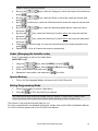
Installer Programming Menu Maps
[1] System
[11] Time Define
[111] Ex/En Delay 1
[112] Ex/En Delay 2
[115] S. Aux Break
[116] WL MOD. Times
[119] More
[1191] Phone Line Cut
Delay Time
[1192] Guard Delay
[113] Bell Timeout
[114] Bell Delay
[117] Z. Test Times
[118] AC Off Delay
[1201] Quick Arm
[1202] Quick UO
[1203] Allow Bypass
[1215] Code GM
[1216] Audible Jam
[1217] Technician
Tmpr
[1218] Technician
Reset
[1219] Abort Alarm
[1229] GM AUT/PAR
[1230] Double Code
[1231] Disarm Stop FM
[1220] Summ/Win
Clock
[1221] Forced KSW
[1222] Pager
[1234] DIS Keypad Auto
Disarm Exists
[1235] Aud Prx TMP
[1236] AM=Tamper
[1223] Arm Prewrn
[1224] L.Batt.Arm
[1237] Prox AM=Tamper
[1238] SIRN AUX=TMP
[1225]
[1226]
[1227]
[1228]
[1239] GSM Pre-Alarm
[1240] Dis. GSM Bat
[12] System Control
[1204] Quick Bypass
[1205] False Code
Trouble
[1206] Bell Sqk
[1207] Bell 30/10
[1208] Alm Phone
Cut
[1209] 3 Min Bypass
[1210] Dbl Ver Fire
Al
[1211] Aud Panic
[1212] Buzz->Bell
[1213] Alarm ZE Cut
[1214] Fire Temp
Pattern
ENG Tamper
Blank Display
24H Bypass
IMQ Install
[1232] Global Follower
[1233] Area
[13] Set Clock
[131] System Date
[132] System Time
[141] Window Start
[142] Window Stop
[14] Windowing
[15] System Labels
[16] Tamper Sound
[161-5] Tamper
Sound
[17] Default
Enb/Disb
[18] Service Info
[181] Service
[182] Service Phone
[19] System
Version
20
ProSYS Quick Programming Setup
[143] Window Days
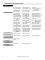
[2] Zones
[21] One by One
[22] Partitions/Group
[23] Zone Type
[23zz00] Not used
[23zz01] Ex/En1
[23zz08] I+Ex(Op)/En
[23zz09] I+En
Follower
[23zz10] I+Instant
[23zz11] UO Trigger
[23zz12] Day Zone
[23zz13] 24 Hours
[23zz14] Fire
[23zz15] Panic
[23zz16] Special
[23zz17] Pulsed KSW
[241] Silent
[242] Bell Only
[243] Buzzer Only
[244] Bell+Buzzer
[245] Door Chime
[246] Bell/A Buz/D
[2501]
[2502]
[2503]
[2504]
[2505]
[2506]
[2507]
[2508]
BUS Zone
TEOL
BZ Input N/C
BZ Input EOL
[2509] BZ Input DEOL
[2510] BZ Input N/O
[2511] BZ Input TEOL
[291] Copy Zone
[292] Delete Zone
[293] Add/Copy Par.
[294] Delete Par.
[295] WL Calibrate
[296] WL Zone Alloc
[297] WL Comm. Test
[298] Zone Self Test
[299] Soak Test
[201] Forced Arming
[202] Pulsed Counter
[203] BUS Zone Prms.
[23zz02]
[23zz03]
[23zz04]
[23zz05]
[23zz06]
[23zz07]
Ex/En2
Ex(Op)/En
En Follower
Instant
I+Ex/En1
I+Ex/En2
[23zz18]
[23zz19]
[23zz20]
[23zz21]
[23zz22]
Exit Termination
Latch KSW
EN.Fol+Stay
KSW Delay
Latched KSW Dly
[24] Zone Sound
[25] Termination
N/C
EOL
DEOL
N/O
[26] Loop Response
[27] Cross Zone
[271] Zone Crossing
[28] Labels
[29] Maintenance
[20] Miscellaneous
ProSYS Quick Programming Setup
21
[3] Utility Output
[30] Nothing
[31] System
[3101] Bell Follow
[3107] AC Loss Fol
[3102]
[3103]
[3104]
[3105]
[3106]
No Tel Line
Comm. Fail
Trouble Follow
GND Pulse
Low Bat. Fol
[3108]
[3109]
[3110]
[3111]
[3112]
[3201]
[3202]
[3203]
[3204]
Ready Follow
Alarm Follow
Arm Follow
Burglary Follow
[3209]
[3210]
[3211]
[3212]
Sensors Test
Voice Module
Battery test
Bell Burglary
Scheduler
[3113] D Key Reader
Comm
[3114] Switch AUX
[3115] GSM Error
[3116] GSM:PSTN Loss
[3117] GSM:Low Bat
[32] Partition
[3205] Fire Follow
[3206] Panic Follow
[3207] Special
Emergency Follow
[3208] Duress Follow
Buzzer Follow
Chime Follow
Ex/En Follow
Fire Trouble
Follow
[3213] Day (Zone)
Follow
[3214] Gen Trouble
Follow
[3215] Stay Follow
[3217]
[3218]
[3219]
[3220]
Disarm Follow
Bell Follow
Bell Stay Off
Zone Bypass
[3221] Auto Arm Alarm
[3222] Zone Loss Alarm
[3216] Tamper Follow
[33] Zone
[331] Zone Follow
[332] Alarm Follow
[333] Arm Follow
[334] Disarm Follow
[3401] Pulse N/C
[3402] Latch N/C
[3403] Pulse N/O
[3404] Latch N/O
[34] User Code
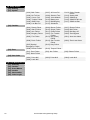
[4] Code Maintenance
[41] Authority
[42] Partition
[43] Grand Master
[44] Installer
[45] Sub-Installer
[46] Code Length
22
ProSYS Quick Programming Setup
[5] Dialer
[51] Link Up
[511] MS Link Up
[512] U/D Phones
[541] Access Code
[542] ID Code
[543] MS Lock
[5501] MS Enable
[5507] User Initiate
[5513] Show Handshake
[5502] FM Enable
[5503] U/D Enable
[5508] Callback U/D
[5509] Autobatch
[5514] Audible Kissoff
[5515] UD GSM Enable
[5504] Call Delay
[5516] X.Modem Enable
[5505] Dial Tone
[5510] Answer
Machine
[5511] UL Installation
[5506] Call Save
[5512] Show Kissoff
[561] MS Retries
[564] Dial Tone Time
[567] Pulse Duty Cycle
[562] FM Retries
[563] Rings to U/D
[565] Redial Wait
[566] Dial Method
[568] Swinger Limit
[569] VM Retries
[571] MS Arm/Disarm
[573] MS Non Urgent
[572] MS Urgent
[574] Follow Me
[575] Email (See Email
table)
[576] Event Log
[581] On Bell Time Out
[582] Follow Zone
[583] At Disarm
[591] MS Test
[592] UD Test
[501] Auto Codes
[502-6] ACM
Parameters (See ACM
table)
[52] Cust.
Accounts No.
[53] Comm Format
[54] Access & ID
[55] Control
[56] Parameters
[57] Report Split
[58] Alarm Restore
[59] Periodic Test
[50] More
[6] Report Codes
[61] Emergency Key
[62] Zones
[63] Accessory
Tamper
[64] Main Trouble
[65] PS Trouble
[66] Arm Codes
[67] Disarm Codes
[68] Miscellaneous
[69] Special Comm
[60] Accessory Code
ProSYS Quick Programming Setup
23
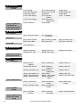
[7] Accessories
[71] Add/Delete
module
[711]
[712]
[713]
[714]
Keypad
Zone Expander
Utility Output
Power Supply
[715] Event Logging
[716] WL Button
[72]
[73]
[74]
[75]
[717] Printer Module
[718] Access Control
[719] More
[7191] Dig Key
Reader
[7192] Advanced
Digital Voice
[7193] ACM
[7194]
[7195]
[7196]
[7197]
Siren
BUS Zones
GSM
X. Modem
Verify Module
BUS Test
BUS Scanning
Auto Settings
[8] Miscellaneous
[81] Keyfobs
[811] WL Button Param
[812] WL Button
Allocation
[821] Strobe Control
[822] Strobe Blink
[823] Strobe Arm SQK
[824] Siren LED
[826] Proximity Level
[827] Bat. Load Test
[91dd1] Partitions
[91dd2] Door Time
[91dd3] Door Fire
[91dd4] Door Input
[91dd5] Door Label
[5021] ACM IP
Address
[5022] ACM UD Port
[5027] Gateway IP
[50203] DNS 1 IP
[5028] Software
Update IP
[5029] Software
Update Port
[5020] More
[50201] U/D IP Mask
[50202] ACM Net
Name
[50204] DNS 2 IP
[5033] ACM AUX1
Config
[5034] ACM AUX2
Config
[5035] ACM AUX3
Config
[5042] ACM MS
Secondary
[5043] ACM MS Backup
[82] Siren
[83] GSM
(See GSM table)
[9] Access Control
[91] Door Define
[92] Card Code Pos.
[93] Special Code
ACM
[502] ACM
Parameters
[5023] ACM AUX1 Port
[5024] ACM AUX2 Port
[5025] ACM AUX3 Port
[5026] Subnet IP Mask
[50205] NTP IP
[50206] NTP Port
[50207] NTP UPD Time
[503] ACM Control
[5031] ACM Config
[5032] ACM UD Config
[504] ACM MS
Polling
[5041] ACM MS
Primary
[505] ACM Function
[506] View ACM
Config
24
ProSYS Quick Programming Setup
Email
[575] Email
[5751] Mail IP
Address
[5752] Mail SMTP
Port
[5753] Mail POP3
Port
[5754] Email Prefix
[5757] SMTP Password
[5755] Email Domain
[5756] SMTP User
Name
[83] GSM
[831] GSM
Parameters
[8311] GSM Mode
[83111] GSM Backup
[83112] GSM Only
[83113] GSM Main
[8212] GSM Times
[83121] PSTN Lost
[83122] GSM Lost
[83123] SIM Expire Date
[8313] Prefix
[8313 1 to 2] PBX Prefix
[8313 3 to 8] Prefix
Constant
[83139] Remove Prefix
[83130] Add Prefix
[8314] PIN Code
[8315] GPRS
[83151] APN Code
[83152] GPRS User
Name
[83153] GPRS Password
[83154] GPRS MS
Polling
[831541] GPRS Primary
[831542] GPRS
Secondary
[831543] GPRS Backup
[8316] Email
[83161] SMTP IP
Address
[83162] SMTP Port
[83163] SMTP User
Name
[83164] SMTP Password
[83165] SMTP Email
Prefix
[83166] SMTP Email
Domain
[8317] Caller ID
[8318] RSSI Level
[832] GSM Control
[8321] Disable In.
Call
ProSYS Quick Programming Setup
25
Technical Specifications
Main
Input Power:
Current Consumption:
Rechargeable Standby
Battery:
Power Outputs:
Programmable Voltage:
Fuses:
16.5 Volts AC @ 40 Volt-Amps (VA) (via integral transformer)
60 mA, typical / 70 mA, maximum
12 Volts up to 17 Amp-Hours (AH)
Auxiliary Power: 12 Volts DC @ 600 mA, maximum (from all AUX
terminals)
Bell/LS (External): 12 Volts DC @ 900 mA, maximum
UO1: Relay (programmable output) (3 Amps)
UO2: 500 mA transistor
UO3-UO6: Open Collector Active Pull-Down, 70 mA, max
F3 Responsible for:
Battery Power 3.0 A
AUX Automatic fuse
BELL Automatic fuse
8 LED Keypad
Current Consumption:
75 mA maximum
16 LED Keypad
Current Consumption:
75 mA maximum
LCD Keypad
Current Consumption:
100 mA maximum
Proximity LCD Keypad
Current Consumption:
160 mA maximum
Touchscreen Keypad
Current Consumption:
180 mA maximum
Touchscreen Keypad with Proximity
Current Consumption:
210 mA maximum
8 zone expansion module
Current Consumption:
45 mA maximum
16 zone expansion module
Current Consumption:
45 mA maximum
BUS Zone Expansion
Current Consumption:
20 mA, typical
8,16 wireless zone expansion module
Current Consumption:
Frequency:
40 mA maximum
868.6-868.7 MHz (narrowband operation in EU) or 433.92 MHz
4 relay output expansion module
Current Consumption:
Contacts:
Contact rating:
25 mA typical / 140 mA maximum
4 Form C (SPDT) Relays.
3 A / 24V DC
8 transistor output expansion module
Current Consumption:
Contacts:
25 mA typical / 30 mA maximum
Open Collector, Active Pull-Down, 70 mA maximum
1.5A Power Supply Expansion Module
Input Power:
Rechargeable Standby
Battery:
Power Outputs:
Fuses:
26
16.5 Volts AC @ 40 VA (via transformer)
12 Volts up to 17 Amp-Hours (AH)
Auxiliary Power: 12 Volts DC @ up to 1.5A
Bell/LS (External) Sounder Output:12 Volts DC @ 900 mA, maximum
*: Total current Bell+Aux=1.5A
F1: Battery power 3.0 A
F2: Auxiliary power 2.0 A
F3: Bell/loudspeaker power 1.0 A
ProSYS Quick Programming Setup
3A Power Supply Expansion Module
Input Power:
Rechargeable Standby
Battery:
Power Outputs:
Overload Protection:
On board Utility Outputs:
16.5VAC @ 50VA (via 230VAC / 16.5VAC/50Hz transformer)
12V Up To 21 Amp-Hours (AH)
Auxiliary Power: 3A @13VDC
Bell/LS (External) Sounder Output: 1.7A @13VDC
Automatic Electronic Protection
2 relays, 12VDC @ 3A max Dry Contact Relays
Event Log Expansion Module
Current Consumption:
30 mA, maximum
Printer Module
Current Consumption:
0 mA, maximum
X-10 Transmitter Module
Current Consumption:
30 mA maximum
Access Control Module
Current Consumption:
Input power:
Readers Consumption:
Relay:
100 mA maximum
13.8V DC + 10%
5V / 150 mA maximum
24V DC / 1 A maximum
Proximity Key Reader
Current Consumption:
70 mA, typical / 180 mA maximum
Advance Digital Voice Module
Current Consumption:
38 mA typical / 60 mA maximum
Voice Message Unit
Current Consumption:
Input Power:
9 mA (standby) /
60 mA (active speaking - normal volume) /
130 mA (active speaking - full volume)
8V DC to 14V DC
GSM/GPRS Communication Module
Current Consumption:
Input Power:
During Communication - 300mA, During Standby - 70mA
13.8VDC ±10%
Battery: Lead Acid (rechargeable), 12VDC/1.2Ah
Advanced Communication Module (ACM)
Current Consumption:
300mA@13VDC
Fast PSTN Modem 2400 BPS
Current Consumption:
100 mA maximum
CE Declaration of Conformity
Hereby, RISCO Group declares that this control panel (ProSYS 128, ProSYS 40, ProSYS 16), with
wired accessories (including cables) and wireless accessories, is in compliance with the essential
requirements and other relevant provisions of Directive 1999/5/EC.
For the CE Declaration of Conformity please refer to our website: www.riscogroup.com.
Compliance Statement
Hereby, RISCO Group declares that the ProSYS series of control panels and accessories are suitable
for use in systems designed to comply with PD6662:2004 Security Grade 3, Environmental Class II.
(Security Grade 2 when using Wireless accessories).
The ProSYS series of control panels and accessories comply with the relevant parts of the EN50131
series of standards.
The ProSYS series of control panels and accessories comply with DD243:2004.
ProSYS Quick Programming Setup
27
RISCO Group Limited Warranty
RISCO Group and its subsidiaries and affiliates ("Seller") warrants its products to be free from defects
in materials and workmanship under normal use for 24 months from the date of production. Because
Seller does not install or connect the product and because the product may be used in conjunction with
products not manufactured by the Seller, Seller cannot guarantee the performance of the security
system which uses this product. Seller's obligation and liability under this warranty is expressly limited
to repairing and replacing, at Seller's option, within a reasonable time after the date of delivery, any
product not meeting the specifications. Seller makes no other warranty, expressed or implied, and
makes no warranty of merchantability or of fitness for any particular purpose.
In no case shall seller be liable for any consequential or incidental damages for breach of this or any
other warranty, expressed or implied, or upon any other basis of liability whatsoever.
Seller's obligation under this warranty shall not include any transportation charges or costs of
installation or any liability for direct, indirect, or consequential damages or delay.
Seller does not represent that its product may not be compromised or circumvented; that the product
will prevent any personal injury or property loss by burglary, robbery, fire or otherwise; or that the
product will in all cases provide adequate warning or protection.
Buyer understands that a properly installed and maintained alarm may only reduce the risk of burglary,
robbery or fire without warning, but is not insurance or a guaranty that such event will not occur or that
there will be no personal injury or property loss as a result thereof.
Consequently seller shall have no liability for any personal injury, property damage or loss based on a
claim that the product fails to give warning. However, if seller is held liable, whether directly or
indirectly, for any loss or damage arising under this limited warranty or otherwise, regardless of cause
or origin, seller's maximum liability shall not exceed the purchase price of the product, which shall be
complete and exclusive remedy against seller.
No employee or representative of Seller is authorized to change this warranty in any way or grant any
other warranty.
WARNING: This product should be tested at least once a week.
Contacting RISCO Group
RISCO Group is committed to customer service and product support. You can contact us through our
website www.riscogroup.com or as follows:
United Kingdom
Tel: +44-161-655-5500
[email protected]
USA
Tel: +1-631-719-4400
[email protected]
Italy
Tel: +39-02-66590054
[email protected]
Brazil
Tel: +1-866-969-5111
[email protected]
Spain
Tel: +34-91-490-2133
[email protected]
China
Tel: +86-21-52-39-0066
[email protected]
France
Tel: +33-164-73-28-50
[email protected]
Poland
Tel: +48-22-500-28-40
[email protected]
Belgium
Tel: +32-2522-7622
[email protected]
Israel
Tel: +972-3-963-7777
[email protected]
All rights reserved.
RISCO Group reserves the right to amend the software and features without prior notice.
No part of this document may be reproduced in any form without prior written permission from the
publisher.
© RISCO Group 07/09
5IN1286