1
ELECTRONIC
MOhJLAR
SWITCHING
SYS,TEM
Panasonic
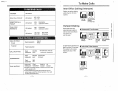
Please read this manual before connecting
Quick Reference
Card for Standard
the KX-T61610.
Telephone
can be found
on pages.+22
through
6-29. _ .
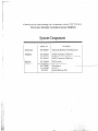
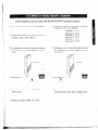
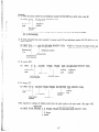
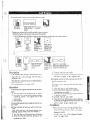
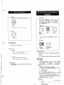
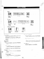
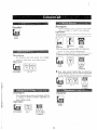
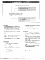
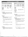
Thank you for purchasing the Panasonic Model KX-T61610,
Electronic Modular Switching System (EMSS).
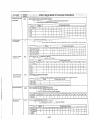
System Component
Description
Model No.
Service unit
KX-7-61610
Electronic Modular Switching System
Telephone
KX-T61620
KX- 7-61630
KX- T61650
EMSS Proprietary TelephotleEMSS Proprietary Telephorze with LCD
EMSS Proprietary Telephone
Optional
equipment
KX- T61640
KX-T30860D(only)
KX- T30865
KX- T30890
KX-Al6
DSS Console
Doorphone Adaptor
Doorphotze
Headset
System Back-up Unit
l-l
..___
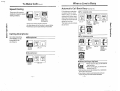
NOTIFY
THE TELEPHONE
COMPANY
Installation must be performed by the telephone company or a qualified professional
installer.
Notify the Telephone Company
Before connecting this equipment to any telephone, call the telephone company and
inform them of the following:
;.’ ),l FCC Registration No. .. . . . . . . . . . . . . . . . . . foul
‘1, .‘* Ringer Equivalence
. . .. .. . . . . . . . . .. . . . .. . : : .. : ..
. l Facility Interface Code . . . . . . . . . . . . . . . . . . . . . . . ; 1.. . . . . . . .,... . :: . . -...02LS2
@Service Order Code . . . . . . . . . . . . . . . . . . . . . . . . . . . . . . . . . . . . . . . . . . 9.OF
@Required Network Interface Jack. . . . . . . ; . . . . . . . . . . . . . . . . .. . . . . . . . . ..‘RJll
: .‘..’
aPresent FCC Regulations prohibit
operated telephone.
connecting this unit to a party line, or to a coin
Please read the section on “Telephone
Responsibilities” on page 6-8.
n
.
Company
and FCC Requirements
and
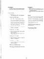
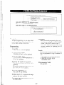
The serial number of this product may be found on the label affixed to the
bottom qf the unit. You should note the serial number of this unit in the space
provided and retain this book as a permanent record of your purchase to aid in
identification in the event of theft.
I
MODEL
NO.: KX-T61610
SERIAL
NO.:
For your future reference
DATE OF PURCHASE
NAME
OF DEALER
DEALER’S
ADDRESS
l-2
:
TABLE CiF CONTENTS
’
.2-1
.2-2
.2-4
Name and Location ...........................................
Installation ......................................................
Connection .....................................................
.2-5
2-5
2-6
Frame Growld Cotmectiotl ......................................
Rechargeable Barfery ltlslallariotz ..................................
Cotltzecrion of The Central Ofice Litle ..............................
Connection of the Extension (for Proprietary Telephone
KX-T61620/KX-T61630/KX-T61650/KX-T30820/KX-T308301
KX-T30850)..................................................2Cotltlecriotl of a Sratldard Telephone to Extensions. ..................
Comreclion of the DSS Console (KX-T61640)
to an Extension. ...............................................
External Music Source ..........................................
Pagitlg Equiptnetlt
...............................................
Cotltlecrion of The Opriotlal Doorphotle (KX-T30865). ................
To Cotltlecr a Polarity Sensitive Telephone ..........................
To Cotmecr Opriotlal System back-up Unit (KX-A16)
................
To Connect Pritlter .............................................
7
2-8
2-9
2-11
2-11
2-12
2-14
2-1.5
.2-16
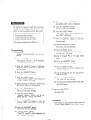
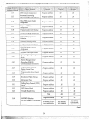
Programming
Programming InsWrtcriotls ........................................
........................................
Example of Programming
3-l
3-3
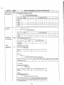
Date and Time Setting ...................
‘87 J&I.
01
12:OOAM
Sysrem Speed Dialing Entry
has t20t heen
stored
.............
THU
.......
3-4
.......
3-5
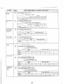
Programmable
Toll Prefix ...............
Programmable
Operator Cull
Programmable
Directory Assistance
with 1
.......
3-22
.......
3-23
no restrict
.......
3-24
Auto Amwer
.......
3-25
Host PBX Access Codes Assignment
has not been
stored
.......
3-26
Preferred CO Line Assignment. ...........
non-assignment
......
.3-27
has been removed
......
‘3-28
Automatic Answering
Selection
Programmable
..........
.- has been added
(AutomaticlManual)
.
.
Call Waiting
.............
all CO’s have
............
Delayed Ringing Assignment
. .3-29
been not delayed
on all extensions
......
Delayed Ringing Count Selection ..........
After 2 rings
.......
.3-30
Intercom Alerting Mode .................
Tone Call
.......
D-phone I,?: : --‘.i .......
3-31
J-3.2
Pi&q-G.-~
i,. .. . c: .......
3-33
...:.....‘S.........
3-34
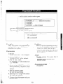
Programmable
Doorphone
.............
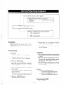
Dial Call Pickup Group Assignment.
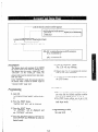
Account Code Input Mode
Duration
......
option
..............
Time Count Start Mode .........
5s a+
-71
&&,:,~7~.& .......
3-3.5
(se@pages$ .,<;?ja. ......
.3-36
system
.:. .......
-;:.,*
.3-41
Disconnect Time .......................
.......
3-50
Calling Party Control (CPC) Signal .......
.......
3-51
DSS Button Mode
.......
3-52
Transfer Recall Time ..................
.......
3-53
M3IFWD Selection (for KX- T308.50,
KX-T616.50) ..........................
.......
3-54
SMDR Communication
System Data Dump
Parameters
......
.....................
Parme@=
SMDR IncominglOutgoing
Hold Time Reminder
‘-
Selection . . . . .
...................
Hold Recall Time Set ...................
Programmable
External Paging Access Tone
Programmable Secret Speed Dial .........
Hookswitch Flash Timing ...............
....................
DetQiled Feature Description and Operation for EMSS
Proprietary Telephone (KX-T61630, KX-T61620, KX-T61650,
KX-T30830, KX-T30820, KX-T30850)
To Make Calls
Inter Ofice Calling (Intercom) . . . . . . . . . . . . . . . . . . . . . . . . . . . . . . . 4-I
Outward Dialing. . . . . . . . . . . . . . . .
. . . . . . . . , . . . . . . , . . . . . . . . . . 4-2
SpeedDialing . . . . . . . . . . . . . . . . . . . . . . . . . . . . . . . . . . . . . . . . . . . . . ...4-3
One Touch Dialing. . . . . . . . . . . . . . . . . . . . . . . . . , . . . . . . . . . . 4-4
Calling Doorphone.
. . . . . . . . . . . . . . . . . . . . . . . . . . . . . . . . . . . . . . . 4-6
Distinctive Dial Tone . . . . . . _ . . . . . . . . . . . . . . . . . . . . . . . . . . , . . . . .4-6
When a Line is Busy
..........................
Automatic Call Back Busy-(Camp-on)
......................................
Busy Station Sigtlaling
Last Number Redial ..........................................
To Receive
4-7
4-8
4-8
Calls
Answer. ........................
Automatic Answer-Intercom
.......
Dial Call Pickup .................
Directed Call Pickup .............
Call Park Retrieve ...............
Doorphone
.....................
Distinctive Ring Totle .............
While Having
..
..
..
..
..
..
..
..
.
..
..
.
..
. . ..
. ..
. .. .
.. .
.. .
.. .
.
.. ..
.. . .
. .. .
. .. .
.. .
. ..
. ..
. .. ...
. .. ...
... .
. . .. ..
.
. . ... .
. . .. ..
. 4-9
. 4-9
. 4-10
4-10
. 4-11
. 4-12
. 4-12
a Conversation
Call ot1 Hold ........................
Call otl Exciusive Hold ...............
Cottference .........................
Call Waiting. ........................
Call Transfer .......................
CalI Splitting-Between CO and Intercom
Call Splitring-ltirercom
...............
. ..
. ..
.
.
.. . .
. .. ..
.
..
..
..
.. ..
..
.. .*
.. . .
.
..
.
..
.
..
4-13
4-14
4-15
4-16
4-l 7
4-18
4-19
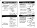
Paging
Pagitlg All Extetzsiotls ........................................
Pagittg Group ................................................
Paging-Extertlal
............................................
Paging And Transfer ..........................................
..............................................
Pagitlg-Answer
4-19
4-20
4-20
4-21
4-21
Use of Other Features
4-22
Backgroutld Music ............................................
4-23
Mule Operation ..............................................
4-23
Otte Tolrch Access for Sys1ettt Features ..........................
4-24
Esrernal Feature Access ........................................
..4-2 5
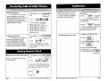
AccountCode..
............................................
.4-27
DSS Console ...............................................
........................................
4-29
PrtlselTone Conversion
..................................................
.4-29
Time Seuitlg
............................................
4-30
Auto CO Hunting
..........................................
.4-31
Flexible CO Button.
Flexible DSS Button ..........................................
4-31
[tl[erconl A[errjtlg Mode, ......................................
.4-32
.:: .........
.4-32
Busy Lamp Field. ................................
4-33
Power Failure Tratrsfer ........................................
4-33
Durariotl Time of CaII Display ..................................
..4-3 3
Lockorir
..................................................
......4-33.
MixedStatiotrDialitrg..
..................................
Station Programming
Dial Call Pickup Detly ,
Call Forwarding . . . . .
Do tlot Disturb . . . , . . .
Data Litle Seclrrity . . . .
.
Saved Nwnber Redial
Flexible Nighr Service . .
Statioti Program Clear .
..
. . ..
..
. . .. . .
..
..
.. . ..
..
..
..
..
. .. .
. .. .
. .. .
.. ..
. .. .
....
..
.. . .
. .. .
.. . .
. .. .
. . ..
. . . . . . 4-34
......
4-35
......
4-37
......
4-35
......
4-38
......
4-39
......
4-40
Operation for a Standard Telephone
To Make Calls ........................
When a Litle is Busy ..................
To Receive Calls ......................
While Havitlg a CotlversaGotl ............
Pagitig ...............................
Use of Other Feamres ..................
Statioti Progratnttiitig
..................
.
.
.
..
..
..
.
.
.
..
.
..
5-l
5-2
5-3
5-4
5-5
5-7
5-10
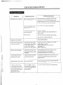
Troubleshooting
Dllritjg It~stallatiot~
Dirritig Cotitiectioti .
.. .
Dldritlg Operatiotl
.
.
Reser Buttot
. .. .
.
DT,UF Recei\*er Check ;!. . . .
................................
................................
................................
................................
................................
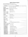
Table of System Features ....... ;:. .............................
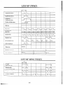
List of Tones ....................................................
List of Ring Tones .............................................
SpeciJication
..................................................
Telephone Company and FCC Requirements
and Responsibilities ........................................
Others ..........................................................
Warranty ........................................................
Servicerzter List ................................................
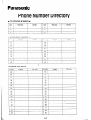
Phone Number Directory ....................................
Programming Table ..........................................
Quick Reference Card for Standard Telephone ...........
l-6
6-l
6-2
6-3
6-3
6-4
6-j
6-6
6-6
6-7
6-8
6-g
6-10
6-11
6-12
.6-14
.6-z
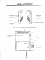
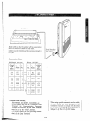
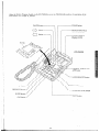
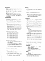
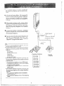
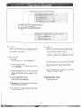
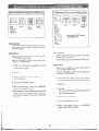
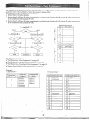
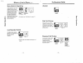
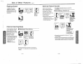
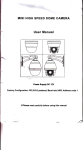
NAME AND LOCATION
:
Night ltldicator
Day Indicator
External Music Jack
Power Indicator
Burtotl B
Ground Terminal
Buttery Backup Cotztlecio
EIA Cotmector
(RS-232 C)
Push Buttons A and B simultaneously to open Front Cover.
Modular Jacks
y-Jtariotl
3IT-I
17
“I
Outside ModularJacks (CO)
0
Reset Button
System Program Switch
I
0
L-zz*Power
0
SwiWh
--
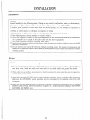
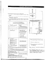
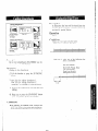
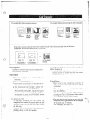
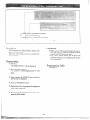
INSTALLATION
Installation
Cautions
*Avoid insralling in the following
places. (Doing so may resulr in malfunction,
noise, or discoloration.)
1. In direct sunlighr and her, cold, or humid places. (Temperarure range: 32”F-104°F)
2. Sulfuric gases produced .in areas where there are thermal springs, etc. may damage the equipment or
contacls.
3. Places in which shocks or vibrations are frequent or strong.
4. Dusty places, or places where water or oil may come into contact with the unit.
5. Near high-frequency sewing machines or electric welders.
6. On or near computers, relexes, or other office equipmenr, as well as microwave ovens or air condirioners.
(Ir is preferable not lo install in the same room with the above equipment.)
7. Near radio broadcast anlennas (including short wave).
8. Insrall at least 6 feet from radios and relevisiotls. (both rhe electronic modular switching system and EMSS
proprierary telephones)
9. Do not obslrucr area around (he electronic modular swirching system. (for reasons of nlaitlfetlatlce
atId
inspecrion-be
especially careful lo allow space for cooling above and at rhe sides of the electronic modlilar
swirchitig sysrem)
Cautions
1. Do not wire the telephone cable in parallel with the AC power source, computer, telex efc. If the cables run
near rhose wires, shield the cables with metal tube ‘or use shield cables and ground the shields.
2. When cables run on the floor, use protectors or the like lo protect the wires where they may be stepped on.
Avoid wiring under carpets.
3. Avoid using the same AC 120 V power supply outlet for computers,
Otherwise, the KX-%1610’s
system operation may be interrupted
telexes, and other office equipment.
by the inducrion noise from such
eqLtipnzenK.
4. Please use one pair telephone wire for extension conneclion of (telephone) equiptnents such as standard
telephone, data terminal, answering machine, computer, etc., except proprietary telephone (KX-T61630,
KX- T61620, KX- T61650, etc.).
2-2
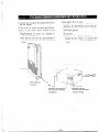
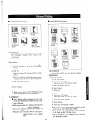
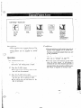
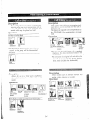
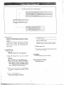
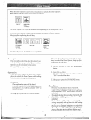
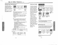
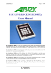
The wall where the KX-T61610 is to be mounted must be able to support a weight of KX-T61610.
than the ones supplied are used, use the same-sized diameter screws as the enclosed ones.
-------
_________
----a---------------
To Wall Mount:
other
____
To Mount on Concrete or Mortar
Walls:
1. Place the templet (included) on the wall to mark
the 3 screw positions.
I
If screws
1. Place
the templet
positions.
1
(included)
to mark 3 screw
2. Drill 3 holes and drive the anchor plugs (included) with a hammer, flush to the wall.
To the wall surface
Concrete Wall
2. Install the 3 screws into the wall.
3. Install
the 3 screws into the anchor plugs.
Drive the screw
to this position.
3. Hook
the unit on the screw heads.
4. Hook
2-3
the unit on the screw heads.
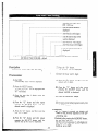
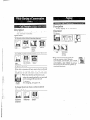
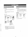
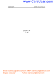
CONNECTION
After all the connections are completed,
the Power Switch ON.
turn
If an extension does not operate properly
(for example: The LCD of the KX-T6163Ol
Speflker
KX-T30830
does not display properly.),
disconnect the telephone from the ejctension
line and then connect again, or turn OFF
the power switch of the KX-T61610
and
then ON again.
Amplifier
Opriotlai Sysrem Back-up
Unit (KX-A16)
(Two pair)
Printer
Doorphotw
I
16 Esretlsiotz Litles
of tile KX-T616301
KX- T6162Of KX- T6165Ol
KX- T3083O/KX- T3082Ol
KX-T30850 is impossible.
(One pair)
l
(Two oair,
Standard
Exretlsiotl I I ttws~
a1rcay.s be KX-T61630
Telephone
KX-T61620
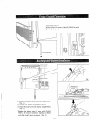
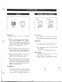
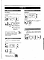
IMPORTANT!!!
Surely connect the frame of the KX-T61610 to earth
ground properly to protect the unit.
/TV /
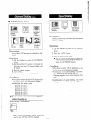
1. Remove the battery cover
from the compartment.
(Fig. 1)
2. Connect the battery (included). (Fig. 2)
3. I~tstall the battery i,lto the battery compartment.
(Fig. 3)
*Replace the battery every 5 years with (P-OlHFIGI).
To remove comlector. depress to release
a,ld slide (pull) apart connector. (Fig. 2)
Fig. .
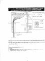
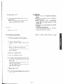
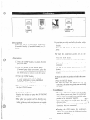
1. Insert
plug of the teleline cord (2-conductor wir-
the modular
phone
ing) into the modular jack
CO) on the KX-T61610.
(marked
2. Place the six telephone line cords
into Holder.
-
RT
Holder (see srep 2)
.u
B
Use 2-condrccror
lcirirlg cord.
To Terminal
Board or Modular
from the Coltral
Office (CO).
R: Ring
T: Tip
View of TEL Jack (CO)
!!
Jacks
Caution
Mis-connection may cause the KX-T61610 to operate improperly.
See “During Installation”
page 6-l and “During Connection” page 6-2 before connecting.
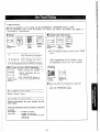
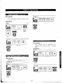
I. Insert the modular plug of the extension line cord (6conductor
wiring)
into the modular
jack (markeci
EXT.) on the KX-T61610.
2. Place the cords into Holder.
L RTH
Holder (see step 2
cB
R:
T:
L:
H:
Ring
Tip
Low
High
View of TEL Jack (extension)
A
-----4-conductor
wiring is
required for each
extemion.
To Extensions
The inner
(DA TA).
l The max.
26 A WC:
24 A WG:
22 A WG:
l
2 wires (red, green) are for Tip and Ring and the outer 2 wires (black and yellow) are for LOW and Hi
length
Under
Under
Under
of the extension line cord that connects the KX-T61610
460 feet
750 feet
1180 feet
Caution
Mis-connection may cause the KX-T614IO to operate improperly.
“During Connection” page 6-2 before connecting.
and the extension is shown belo
See “‘During
-*
Installation”
page 6-l
and
1. Insert the modular plug of the exten-
sion line cord (2-conductor wiring)
into the modular jack (marked
EXT.) on the KX-T61610.
-I -b
k
2. Place the cords into Holder.
\
Outer Z pins (Low and High) will not
be Itsedfor Standard Telephone.
Holder ,
(see srep 2)
R: Ring
T: Tip
Vie)%’of TEL Jack (extension)
Use 2-conducior
ltniring
-
To Extensions
*The max.
length of the
26 AWG: Under 2290
24 AWG: Under 3700
22 A WC: Under 5900
"If
of
extension line cord that connects the KX-T61610
and the extension is shown below.
feet
feet
feet
a telephone or answering machine with an A-Al relay is connected to the KX-T61610,
the telephone or answering machine to OFF.
Caution
Mis-connection
See “During
may cause
Installation”
the KX-T61610
page 6-l and
set the A-Al
to operate improperly.
“Dun’ng
Connection”
2-8
page
6-2 before
connecting.
relay switch
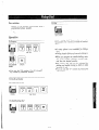
Pair Telephone
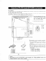
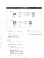
The DSS Console, KX-T61640 needs its Pair Telephone (EMSS Proprietary Telephone) for the operation, becaus’
the DSS console cannot work by itself.
The EMSS Proprietary Telephone (such as KX-T61620, KX-T61630, KX-T61650, KX-T30820, KX-T30830,
KX-T308SO) is required as a pair telephone for dialing, storing, etc.
Place the KX-T61640 and the pair telephone side by side on your desk.
1. Insert the modular plug of
the esten,
sion line cord (4-conductor wiring,
into the modular jack (market
EXT.) on the KX-T61610.
2. Place the cords into Holder.
L RTH
Holder
\ (see step 2)
R: Ring
T: Tip
L: Low
H: High
i
View of TEL Jack (exremion)
1
0
0
!
4-conducror \viritzg is
required for each
exretzsiol7.
l KY-T61640
can not be connected at extension 1
0 Up to 2 KX-T6164Os can be connected to I
KX-T61610. Each console needs its own pail
telephone.
.KX-T61640
can not be connected in pair with
standard telephone.
0 The max. length of the extension lille cord ti
connects the KX-T61610 and the DSS Console
shown below.
26 AWG: Under 460 feet
24 AWG: Under 750 feet
22 AWG: Under 1180 feet
DSS Console
KX-T61640
Pair Telephone
Pair
Caution
Mis-connection may cause the KX-T61610 to operate improperly.
“During Connection”
page 6-2 before connecting.
2-9
See “During
-
Installation”
-
page 6-l ant
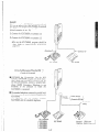
Example:
If y§-e&my has KX-T61630 at exrension 12 and
is to use the DSS console (KX-T61640), rhe console
should be connecled to extension 13.
(Paired extension is ext. 12).
1. Connect the KX--61630
at extension 12.
2. Connect the KX-T61640
at extension 13.
eFor use the KX-T61640, program should be
done. Refer to “DSS Console Assignment”
page 3-8.
Extetlsion 12
KX- T61630
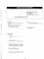
To Use Full Extensions When the DSS
Console is Connected
WKX-T61640
{1
.
H KX-T61610
has 16 extensions. But the DSS
Console, KX-T61640 occupies one of the extensions, which can not make or receive a call. To
use the full extensions, connect a standard telephone (EMSS Proprietary
Telephone is not
available)
to the extension to which the
KX- T61640 is connected.
H The standard telephone connecred in parallel with
KX-T61640 can be used without any affection of
KX- T61640.
The operation
has no concern
between
KX-T61640 and rhe standard telephone.
Pnnnsorzic.KX-J66
Pair Telephone
KX- T61640
1
This is not
Standard
Telephone ca pair telephone.
- -
111
I
J
Use a twoconductor pluo
(?+a inch in dizmete !r)
ehput impeda tnce
-10 dBm
Exterr iaf Music Source
that has
IIcord
an interna
resistance
Speaker
,
\
Amplifier
Use an RCA connector.
eOutpur impedance:
3-11
Adaptor
.
,
lose the Optio/lal Doorphotle
For instaiiitlg the door phone.
Doorp/~orte Adaptor to the KX-T61610
1. f-few to install the
-..-:nr,;r\,rr to the ho/es.
@ posh the adnpror
t .^,.
(use tihe KY-T30860D
t~.nt ;t lnckq itlto the ribs of the mit.
flown 3” ‘,‘L‘L z. .--.--
only).
1
2. Wiring conneCtion of the Doorphone
(A) Connect the doorphone adaptor to the terminal box using a 4-conductor modular -connector.
(B) Connect the wires of doorphone
1 to the red and green screws of the terminal box.
(C) Conrlect the tvires of doorphone 2 to the yellow and black screws of the terminal box.
Doorphone Adaptor
(KX-T30860D
orlly)
Terrniml
Box
Doorphone
Doorphone I (KX-T30865)
BLACK
@The max. length
below.
26
24
22
of the telephone line cord that connects the KX-T61610
AWG:
AWG:
AWG:
.______---.------,--.-.---.- -- -...-- .-..______
.:.
Under 230 feet
Under 370 feet
Under 590 feet
..
,
2-13
2 (KX-T308t
-
and the doorphone
(KX-T30865)
is she
If
the telephone you are using with the KX-T61610 is polarity sensitive.
6. Confirm
that dialing can be done on following
exrensiotis iisirig a rotze telephone.
1. Cotmeci all extension wiritlg lo the KX-T61610.
2. Cotlfirtn that dialitlg can be done from
estetlsiotls using a tone relephotle.
Exlension
Extetisioti
Extension
Extension
Esterisioti
Extensiotz
all the
3. If a dialing cat1 tlof be dotle, rhe polarify berlcseen
the exretlsiotl atld rhe h’X-T61610 musI be re\,ersed.
7.
Il.. . CO
12...CO
13... CO
14...CO
15...CO
16.. . CO
I
2
3
4
5
6
If dialing cat1 not be done, the polarity between
rhe KX-T61610 atld the Cerltral Ofice Lirle tnust
be reversed.
E.uerlsion
Extension
Cenirul Office Line
Re\.ersehere
4. Ser rhe Power Switch ot1 the KX-T61610
OFF positiotz.
5. Connect all Central
O.ffice (CO)
to the
8.
If
any extetlsiort is changed or replaced, repeal
these procedures (from step 1 through step 7).
Lines.
2-14
.
1. Connect the cord from
the KX-T61610.
the optional
2. Plug in the AC power cord from
KX-Al6
l The Battery life is 3 years.
l A simple way to check the KX-A16
to
is to
disconnect the KX-T61610 and the KX-A16
from the AC outlets, and then observe if the
KX-T61610 operates.
elf the KX-T61610 does not operate, recharge
the KX-A16.
eAC Primary Fuse, (250 V, 1.25 A)xl:
Replace the fuse which is in the fuse hold
located on the rear, if the CHARGE Indicate
is off
the KX-A16.
3. Turn on the Power Switch located on the
KX-A16.
OApproximately
24 hours are required
to
recharge the KX-A16.
@The KX-A16 will work for approximately
4
hours (on the average) in the event of a power
failure.
(Keep the unit CMWJfrom
KX-Al6
BATTERY
,‘---.-
LOW Indicator:
will be lit \vhile recharging
is insfifj5cient.
CHARGE
Indicator:
will be lit while the adaptor
is being recharged.
-
;
1
.. ;
2.:_1
- _..-_.,_.-.- _.*_.._ -...---
.
heat.)
2-15
L
_^ , _
1
Serial Printe;
/*
Make cables so that the printer will be connected to
the KX-T61610 as shown itz the chart.
Cables tnust be shielded and the maximum length is
6.5 feet.
Connection
Chart:
KX-T61610
RS-232C
Printer
RS-232C
Circuit
Twe
VW
Signal
Name
AA
BA
FG
TXD
1 2 --
1
3
FG
RXD
AA
BB
BB
CB
RXD
CTS
CT.9
3 5
2
TXD
BA
cc
AB
DSR
SG
6 -/-7-
20
7
DTR
SG
CD
AB
CD
DTR
5
6
8
CTS
DSR
DCD
CB
CC
CF
Pin
No.
20
Pin.
No.
Signal
Name
C&fit
(YE)
“Panasonic data terminal;
KX-D49IOD,. KX-D4911, KX-D4920, etc.
If you connect this unit to a Panasonic Data
Terminal,
the Communication
Parameter
Transmit XONIXOFF
on the Data Terminal
must be set to the “YES” position.
For further details, see rhe Operating Instructions of the Data Terminal.
When using special acieisories such as cable,
the user should use those specified in this
installation manual to comply with the limits
for a Class A compuring device pursuarit co
Subpart J of Part 15 of FCC Rules.
2-16
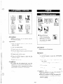
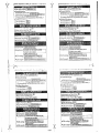
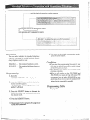
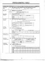
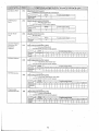
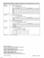
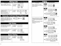
PROGRAMMING
To activate this system, the requirements from telephone company and the customer must be programmed
Power Switch has beet1 turned on.
Preferred CO Litze Assignment
Programmable Cull Waiting
Dltratiotl Time Count Start Mode
SMDR Cotntnunicutiotz Paratneters
System Data Dutnp
SMDR It~cotninglOutgoing
Selection
Hookswitch Flash Tin@
Discotztlect Time
Calling Party Control (CPC) Signal
ltlrercotn Alerting Mode
Progratntnable Doorphone
Dial Call Pickup Group Assigtltnetlt
Account Code Input Mode
Delayed Ringing Assigtnnetit
Delayed Ringing Count Selection
DSS Console Assigtmzettt
Hold Time Retnitldet
Hold Recall Titne Set
Programmable External Paging Access Totle
DTMF Receiver
Programmable Toll Prefix
Programmable Secret Speed Dial
Programtnable Directory Assistance
DSS Button Mode
Transfer Recall Tinte
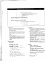
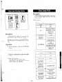
1. At extettsiotl 11:
All system programtnittg changes (example: sy’srem clear. station progratn clear, toll restrictiotl,
hookswitch Posh timing.. .) are dotie throrigh
estetfsioti Il.
OExtensiort II must always be a Panasonic
model, KX-T61630.
2. System Program Sw,itch setting:
The System Progratn Switch located ott the
KX-T61610 must be set to the PROGRAM
position while making program changes. After all
programming changes are completed, return the
program switch to the SET position.
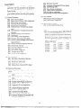
3. Overlay:
This overlay is used for progratmnit~g the system
and the program function names are inscribed on
this card. Refer to page 3-2.
4. Before systetn programming,
operate the system
clear and station program clear to set to the
default data of the progratntnittg.
A. Systetn Clear:
1 Dial (99).
o”SYSTEtVI CLEAR”
lr’ill
2 Press the NEXT button.
o”A LL CL E.4 R?” \c*ill be
3 Press the MEI\IORY
button
4 To exit from system clear.
brittott.
M3IFWD
be displayed.
Selection
B. Station Progratn Clear:
1 Dial (98).
*“EXT
CLEAR”
bvill be displayed.
2 Press the NEXT btrtto:z.
*“ALL
CLEAR?”
isill be displayed.
3 Press the MEMORY
button to clear the
system.
4 To exit from station clear, press the END
button.
displayed.
to clear system.
press the END
The followitlg feutures ure preset as the defatrlt
data.
Dute uttd Time Setting
Systetn Speed Dialing
CO Cotmectiott Assigtrtnettt
Dirt1 Mode (TottelPtrlse) Selection
Slvitchittg Mode (DaylNight Service)
Startittg Titne (DaylNight Service)
Flexible Day Outward Dialing Assignment
Flexible Night Olrtward Dialing Assigtmetlt
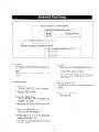
Flexible Day Ritlgitrg Assigtlment
Flexible Night Ringitlg Assignment
Toll Restrictiott-Cluss
Assignment
Toll Restriction-Areu
Code Selectiotz
Progrcttntnable Operutor Cull
Host PBX Access Codes Assignmettt
A tttomatic Atu~vering (A utomuticlMat~uu1)
Selectioti
once the
The follonittg
fcutL(res are preset ns the
defatrlt data.
Otte Tortch Dialittg
Backgroutld Music
Cull-~For~vardittg
Data Line Security
Dial Call Pickup Detty
Do trot Disturb
Auto CO Hunting
Pickup dial
Flexible CO Button
Flexible DSS Buttot
- L
3-l
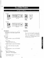
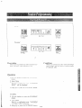
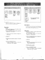
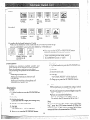
Whet1 the System Program Switch 011 the K-Y-T61610 is set to the PROGRAM
KX-T61630 will change as follows.
PA USE burro,1
I
c7
\
positiotl,
the operatiotl
of the
r------CLEnR
bur
lot’
PROGRAMMABLE
FEA TURE burrotl
bl’rtot’
7
burrotl
-----LIQUID
CRYSTAL
Display (LCD)
-1
KX-T61630
CENTRAL
OFFICE
LINE buttotz
button
AUTOIMEh4ORY
-SELECT
PR EVIOUS brtttotl
FLASH
buttotl
INTERCOM
(ICM)
blcttotr
NEXT burrotl
END buttotz
3-2
(CO)
.
button
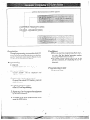
I. Turn the Power-Switch to ON
, .. . . . .. . . .. . . .. . . ... . .. ..
2. Set the System Program Switch to PROGRAM
, . .. .. .. . .. .
The LCD on the KX-T61630 will show “ENTER PGM
CODE”.
@Be sure the handset of extension 11 is in the cradle and the
speakerphone button off.
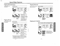
3. To program automatic line access number 9 and the phone
number 987-654-3210 speed access code 00. (Refer to page
3-5.)
KX-T61630 at extension I1
(Extension 11 must be a KX-T61630.)
Dial (01) or press the
A UT0 button.
Press the NEXT button.
Dial (00) or press the
NEXT button.
l-
Display
) SPEED DIALING
]
IC
ENTER SPEED CODE
‘If nothing is stored in
access code “OO”,
100: NOTSTORED
]
‘If already stored the
automatic line access
number 9 and the
phone number
123-456-7890,
00: -123-456-7890
I
@
@
@
@
Press “-‘I button.
Dial “654”.
Press “-“button,
Dial “3210”.
While programming
00: -987-654-3210 1
Press the MEMORY
button.
l
1. Press the “END”
button.
2. Start programming
the beginning.
procedure from
100: -987-6.54-3210 1
I
l
if a mistake is made,
To program the next access code, press the NEXT
button.
To program a desired access code, press the
SELECT button and then dial the number.
eYou will
MEMORY
hear a beep after pressing
button.
*The MEMORY
indicator light will go on
when thF.MEMORY
button is pressed, and
then the Indicator light will go out when the
NEXT or PREV button is pressed.
*
4. Return the System Program Switch to SET
q To make program change, start from the beginning.
-
3-3
the
-
,........_......~....~-~~..-......__...._-._~.....-~.~.-..---~~....-..-..-..~.~--~-.~...enter the year with 2 digits.
[87]: 1987year
i~~“~‘~“~~“““““““““~.“-~‘-‘.““~..~“.”~””’.“””.’~~‘.
until the desired month is
displayed
,_.._.________..__.__.._..._.-~-........__.__...______.__
enter the day with 2 digits
,._...._____._._____..~~~.~~....._____.__
until the desired day of the
week is displayed
,..__..._____.........__..
’ enter the hour with 2 digits
;.‘...‘..““~‘.‘
enter the minute with 2 digits
r.- until the desired AMIPM
\ displayed
is
~~~~[NEXT~[~~[~~~SE~~~T~~O~I~~[~~[SE~~CT~I~I~~~[~~~~~[OI~SE~ECTI[MEMORY~[END]
~
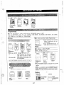
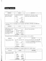
[87 JAN. 01 THU 12:OO AM]...default
Description
Entry
7. Press the “G” button.
“12: 00 AM” will be displayed.
of the current day, date and time.
I!
,.?
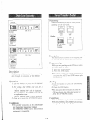
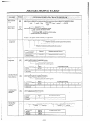
Programming
1. Dial
(00).
“DAMTIME
SET”
2. Press the NEXT button.
“87 JAN. 01 THU” will be displayed and
“87” will blink.
10. Press
the “0”
button and then repeat
pressing the SELECT
button until the
desired AM/PM is displayed.
using the
Il.
4. Press
b utton and then repeat
the “0”
pressing the SELECT
button until the
desired month is displayed.
5.
Press- the “0”
button
day with 2 digits.
the hour with 2 digits.
9. Press the “Q” button and then enter the
minute with 2 digits.
will be displayed.
3. Enter the year (last 2 digits)
dialing button.
8. Enter
Press the MEMORY
button.
12. To return to the initial program mode, press
the END button.
-button is pressed, the display will
return to the previous sequence in the programming step.
Condition
*If “0”
and then enter the
6. Press
the “0”
b utton and then repeat
pressing the SELECT
button until the
desired day of the week is displayed.
@Instantly after pressing the MEMORY button,
the new time will start.
But the LCD of extension I1 will display the
new time only after the Systey Program
Switch is set to SET.
3-4
,
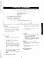
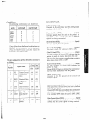
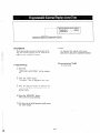
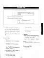
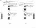
1 AB=[OO]: speed access code 00
[99]: speed access code 99
CD=[
r
91: nutotnatic line access number
[81]: line access number of CO 1
[86]: line access number of CO 6.
A---
tWJWP+W
01
FiyJ[phone
number][MEyORY][END]
-[SELECT]--------I
I-------- until rhe desired speed access code appears
[AUTO][NEXT][N][CD][phone
t-
number][MEMORY][END]
Description
4.
100 phone numbers each with up to 32 digits
may be entered into programming
for speed
dialing use from each exretuion.
Pushing rhe “-3c”, “#” “PA USE”, IL--” or
“FLASH”
button counts as I digit,
Enter the line access number.
9: for
81: for
82: for
83: for
84: for
8.5: for
86: for
automatic
CO 1
CO 2
CO 3
CO 4
CO 5
CO 6
selection
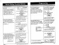
Programming
I. Dial (01) or press the A UT0 button to go
inro the speed dialing entry mode.
“SPEED DIALING”
will be displayed.
2. Press the NEXT button.
“ENTER SPEED CODE”
will be displayed.
3. Dial (00 through 99) or press the NEXT
burron, for speed access code entry.
Example:
When dialing (00) or pressing the NEXT
button.
aThe LCD will show “0O:NOT STORED”
- when nothing is stored in speed access code
“00”. When the automatic line access number 9 and the phone nutnber 123-456-7890
has been stored, “00: -123-456-7590” will
be displayed.
5. Enter the phone number.
0 You may enter punctuations
phone number.
during
a
@To erase a wrong entry, press the CLEAR
button.
6. Press the MEMOBY
burton.
@The memory indicator will be lit.
7. To program desired speed access code, press
the SELECT button and then dial rhe speed
access co&.
To advance to the next speed access code,
press the NEXT bufton.
To return to the previous speed access code,
press the PREV button.
Conditions
8. Repeat steps 4 to 7.
Use the “+‘I, or “Q” button for scrolling the
display.
eThe line access number (9 or 81 through 86)
should be stored.
o When dialing, the pause is automatically
entered after line access number (9 or 81
through 86).
econtinuous
use of speed dialing is possible.
Example:
[AUTO] [Ol] [AUTO] [02]
In this case, speed access code “02” should not
include the line access number.
l
9. To exit from speed dialing entry, press the
END button.
eThe LCD will show .the initial program
mode, “ENTER
PGM CODE”.
To change
Repeat steps 1 to 9.
:
i
i
[
1
i
\
i:
There is a phone
6-12.
To erase after programming
1. Dial (01) or press the AUTO
“SPEED
button.
will be displayeci.
DIALING”
2. Press rhe SEXT button.
“ENTER
SPEED CODE”
plaJ?ed.
will
be dis-
:I:
(00 throqiz
99) or press the NEXT
butron, for speed access code entry.
The speed access code and the phone number
will be displayed.
3. Dial
1
1
1
I
4. Press the CLEAR
L
5.
Press
burton.
the MEMORY
button
6. To program desired speed access code, press
the SELECT blctton and then dial the speed
access code.
To advance to the next speed access code,
press the NEXT button.
Tti return to the previous speed access code,
press the PREV button.
7. Repeat steps 4 to 6.
8. To exit from speed dialing entry, press the
END -buttwl.
3-6
number
directory
on page
Examples
1) To enter line access number 81 and telephone number 201-392-4669 into speed access c&de 00.
(OJ NEXT -7
00 81- 201-392-4669
i i
Teleihone
Speed access !
number
code
line a’ccess
number
aIf
MEMORY
punctuations are not entered during
(00: 812013924669)
2) To enter automatic
access code 02.
END)
a phone
number,
the LCD
will show as below.
line access number 9, account code 1234 and telephone number 201-392-4669
(OJ NEXT O? ? -x -x q4
201-392-4669
MEMORY
END)
I
: i
Speed access [
code
automakc line
access number
into spee
0 Refer to “Account code Input mode” pag
3-34 and “Account code” page 4-25.
j Teleph’one number
II
account code
3) To access MC1
(OJ
NEXT
O_ 9II
Speed acc&s i
I
code
I
123-4567
MCI number
PAUSE
PAUSE 9876 201-348-7000
: - - - - _,- -- - ___
Secirity
Teleihone
I
code
number
automatic line
access number
PA USi
MEMORY
END)
button
4) To access ITT
(Q1 NEXT
02 8;
Speed acc&s
code
;
It
I0
7654321
(Ql
ITfnumber
E=
201-348-7000
Telephone
number
!
PA “il.5
to change the dialing
pulse mode
NEXT02
PAUSE
I-- - ,- - --2
I
I
Line hccess
number
When required
PAUSE
6789 MEMORY
END)
Seckty
code
button
mode from
the pulse mode to the tone mode.
tone mode
* # PAUSE PAUSE 201-348-7000
-7-F
: :
i i button
* button
3-7
MEMORY
(See page 4-29)
END)
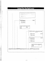
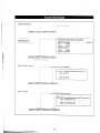
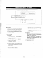
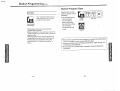
Console 1 extension number
Telephone extension number
paired with console 1
I
,-. . . . . . .. . . .._.____......._....................
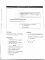
CD+ 11: orl extension11
I
[26]: on extension 26
Console 2 extension number
EF=[12]:
on extension 12
Telephone extension number
paired with console 2
[02][NEXT]i
Y,‘r
..
3-8
D&xription
Conditions
l DSS console can be connected up to two.
0 DSS console can not be connected in pair wit
a standard telephone.
0 DSS console can not be connected at extensio
11.
If a DSS console is used the extension number
paired with the DSS console should be assigned.
Programming
1. Dial
(02)
“DSS CONSOLE
Example:
If Mr Jay’s secretary has KX-T61630 at extension 12 and is to use the DSS console (KXT&640), the console should be connected to
extension 13. (Paired extension is ext. 12.) Mr
Brown’s secretary has KX-T61620 at extension
14 and is to use the DSS console (KX-T61640),
the console should be connected to extension 15.
(Paired extension is ext. 14.)
SET” will be displayed.
2. Press the NEXT button.
The LCD
will show “C
-T
,
C. .-T.
.” when nothing is stored.
When console 1 has been stored to extension 12, the pair telephone with the console
1 has been stored to extension 13, the
console 2 has been stored to extension 14
and the pair telephone with console 2 has
been stored to extension 15, “C12-T13,
C14-T15” will be displayed.
l
3. Dial the extension nlonber
console 1 is connected.
l
l
l
to which the
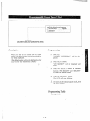
Programming Table
See page 6-14.
4. Press the “ 0 ” button.
5. Dial the extension number which is paired
with the console 1.
‘If you don’t connect the console 2, proceed to step 10.
6. Press the “ 0 ” button.
7. Dial the extension number
console 2 is connected.
8. Press
to which the
the ‘I 0 ” button.
9. Dial the extension number which is paired
with the console 2.
10. Press
the MEMORY
button.
11. To
return to the initial program mode, press
the END button.
3-9
r
:_.~.*~--~.~~
Ltrrtil the desired CO number appears
: ;_
_____
.__
____
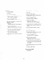
[03] [NEXT] [w]
[SELECT] [MEYORY]
T
or
[END]
I
[03] [NEXT] [Al [SELECT] [MEMORY]
[END]
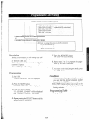
A=*:
to &sign the same on all 6 CO’s
1: 0nCOI
Description
Conditions
You can program which outside line is con?,
netted and which one is not connected.
.
When an extemion automatically selects ali idle
outside line, the extetlsioll can be connected to it
quickly.
l
::
Programming
1. Dial (03).
“CO
CONNECTION”
2. Press the NEXT button.
“ENTER CO NO” will be displayed.
1. [03] [NEXT] [(NEXT) or (l)] [MEMORY]
2. [NEXT] [MEMORY]
3. [NEXT] [SELECT] [MEMORY] [END]
3. Press the NEXT button.
“CO 1: CONNECT”
will be displayed and
“CONNECT”
will blink.
Programming
4. Press the SELECT button, to alternate between CONNECT and NO CONNECT to
select the desired mode.
See
5. Press the MEMORY
button.
The LCD -will stop blinking.
the dialing
7. To return to the initial program mode, press
the END
l
Example:
CO 1 and 2 . . . . . , . . . . . . . . . CONNECT
CO 3 . . . . . . . . . . . . . . . . . . NOCONNECT
will be displayed.
6. Repeat steps 3 to 5, to program
mode on the other CO lines.
When you start the programming from step 1,
may
dial the desired CO number instead
of the NEXT button at step 3.
The PREV btctton allows you to see the entr)
status iti the previous CO cotinectio~i assigriment.
yowl
button.
3-10
page
6-14.
Table
I~-~~---~-~~~--~
until the desired CO number appears
[0orq][NEXT] [Al [SELECT] [MEMORY]
[END]
pI’[+$]:
Conditions
Description
Allows the user to select rhe dialing mode (tone
or pulse) of each CO (Central Ofice) line.
*TONE Dial Mode
The dial signal from rhe extension (ivith tone or
pulse dial mode) will be converted to TONE.
TONE will rhen be transmitted to the Cenrral
Office.
l PlJLSE Dial Mode
The dial signal from rhe extension (with tone ot
p&e dial mode) will be converted to PULSE.
PULSE will then be transmitted to the Central
Ofice.
Programming
1. Dial (04).
“CO DIAL
to assign the same on all 6 CO’S
MODE”
will be displayed.
2. Press the NEXT button.
“ENTER CO NO” will be displayed.
3. Press the NEXT button.
will be displayed and
“CO 1: TONE”
“TONE”
will blink.
4. Press the SELECT button fo alternate between TONE and PULSE.
5. Press the MEMORY
butron.
-The LCD blinking will stop.
6. Repeat sreps 3 to 5, to progratn the dialing
mode on the other central ofice lines.
7. To return to rhe initial program
the END burton.
mode. press
0 When you start the programming frotn step 1,
you may dial rhe desired CO number instead
of the NEXT button at step 3.
l The PREV button allows you to see the entry
status in the previous CO dial mode.
‘If the KX-T61610 is connected lo rhe Central
Office directly or installed behind a host PBX,
which receives both tone and pulse dialing
mode, the KX-T61610 must be used only in
the lone dial mode.
‘If your extension is not a KX-T61630,
KX- T30830,
KX-T61650,
KX-T61620,
KX-T30820 or KX-T308SO but a standard
telephone, and the dial tone frequency of CO
Lines is 600 Hz, the KX-T61610 tnust be used
only for the pulse dial mode of CO Lines.
Example:
l TONE
on the CO 1=
[04] [NEXT] [l] [MEMORY]
[END]
or
[04] [NEXTJ [NEXT] [MEMORY] [END]
*PULSE on the CO 2=
[04] [NEXT] [2] [SELECT] [MEMORY] [END]
or
[04] [N&T]
[NEXT] [NEXT] [SELECT]
[MEMORY] [END]
Programming
See page
6-14.
Table
;-e-o
--.-...__......
_._._._._-_..___
-._-
_..-_._.
a.
:
-
[05] [NEXT] [SE&CT]
[MEMORY]
[END]
Description
Conditions
Allows DaylNight service to be selected manrtally or automatically.
In case of manual switching, refer to “Flexible
Night Service” page 4-39.
When the Switching mode (Day/Night Service)
is set to “AUTO”,
the present DaylNight
Service mode will not change after you finish
programming.
To change the present mode,
manual operation is required.
After you selected the Starting time (DaylNight
Service} page 3-13, select the present DaglNight
mode by “Flexible Night Service” puge 4-39.
In case of automatic switching, set the “Starting
Time (DaylNight Service)” page 3-13.
_
The following features should be set.
@“Flexible Day Outward Dialing Assignme@”
page 3-15.
0 “Flexible Night Outward
Dialing Assignment” page 3-16.
0 “Flexible Day Ringing Assignment” page 3-l 7.
~“Flexible Night Ringing Assignment” page
3-18.
Programming
1. Dial (05).
“DAYINIGHT
.,
MODE”
will be displayed.
2. Press the NEXT button.
“MODE CHANGE:MAN”
will be displayed and “MAN”
will blink.
3. Press the SELECT button to alternate between “MAN”
and “AUTO”
to select the
desired mode.
4. Press the MEMORY
button.
The LCD -will stop blinking.
5. To return to the initial program
the END button.
mode, press
:i
Programming
See page 6-14.
Table
I
.
‘._-...__-_-_.....-......-.-... A=[011 (o’clock):, $arting time for day service
[ 121 (O’cfock)
.~.~~~~~~~~~~~~~-~~~.
B=[OO] (minute) . . . . . . . . . . . . . . . . . . default
[O:] (minute)
[59] (minute)
I
.-- . ..__.__ until the desired mode appears
AM
. . . . . . . . default
PM
C
I..
1
~~~~~~--~.
C=[OI] (o’clock):
[+I (o’clock)
starting time for night
service
. . . . . . . . . . . . default
[1’2] (o’clock)
D=[OO] (minute).
[Ol] (minute)
. . . . . . . . . . . . . default
[59] (minute)
/jzJr&q
:. until the desired mode appears
[06][NEXT]
-ECT][MEMORY][NEXT]
7
73
Conditions
Description
If you select the automatic switching mode for
daylnight service, enter the starting time.
Refer to “Switching Mode (DaylNight Service)”
page 3-12.
Programming
1. Dial (06).
“DAY/NIGHT
TIME”
elf the NEXT button is pressed at step 3
through 7, the display will advance to the
“Night Time input” mode (step 9). The
operations of step 3 through 7 are not stored.
l if the PREV button is pressed at step IO
through 14, the display will return to the “day
time input” mode (step 2). The operations of
step 10 through 14 are not stored.
will be displayed.
2. Press the NEXT button.
“DAY: 09:OO AM” will be displayed
default value and “09” will blink.
Example:
8.30 AM... starting time for day plan
6:30 PM. . . starting time for night plan
as a
3. Enter the starting time for day service using 2
digits.
4. Press the “Q” button.
“00” will blink.
Programming
See page
5. Enter the minute using 2 digits.
6. Press the “0”
button.
“AM” will blink.
A
7. Press the SELECT button to alternate between “AM” and “PM” to select the correct
setting.
8. Press the MEMORY
button.
9. Press the NEXT button.
“NIGHT:
OS:00 PM” will be displayed as a
default value and “05” will blink.
10. Enter the starting time for night service using
2 digits.
11. Press the “0” button.
“00” will blink.
12. Enter the minute using 2 digits.
13. Press the ‘IQ” button.
“PM” will blink.
14. Press the SELECT button to ,alternate between “AM” and “PM” to select the correct
setting.
1s. Press the MEMORY
button.
16. To return to the initial program
the END button.
mode, press
6-14.
Table
;------------until the desired extension number appears
; .. .‘.
;-v’m’---- ,dial the CO number
..j !23&56+.;..
,. il(CLEAR) ‘,
[07] [NEXT] [NEiT] &
t
PO:] [NEXT] [AB] [C...E]
-
.,.
[MEMORY][END]
[MEMOFiY][END]
‘“--“-‘--‘---““-----~
AB=[*]:
to assign the same on all16 extensions
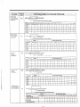
Description
Conditions
Through programming,
you can select which
extensions may be used for outward dialing by
using the day mode of operation.
*When you start the programming from step 1,
you may dial the desired -extension. number
instead of the NEXT button at step 3.
@The PREV button allows you to go to the
previous extension for displaying the CO
assignment.
Programming
1. Dial (07).
“DAY: OUT CO”
.,:;.;:.
:.
:::,:;-” :,.
:; ...‘.‘-.
defaulf (all 16 &~eil&n~) :’
,,.’
.‘. .. ....
Exanzple: COMPANY XYZ
Company XYZ wants only extension 11 and 15
to have access to CO 1, 2 and 3 on outgoing
calls during the day. Extensions 12, 13, 14, 16,
17 and 18 are to be programmed for access to
only CO 1 and 2.
will be displayed.
2. Press the NEXT button.
“ENTER EXT NO” will be displayed.
3. Press the NEXT button.
“11: CO 12 3 4 5 6” will be displayed and “1
2 3 4 5 6” will blink.
1. [07] [NEXT]
2.
3.
4.
5.
6.
7.
8.
4. Dial the CO number to be entered.
The desired combination of CO lines will be
displayed.
To prohibit dialing, press the CLEAR button
instead of the CO number.
“11: CO.....” will be displayed.
5. Press the MEMORY
button.
The LCD will stop blinking.
[MEMORY]
[NEXT] [I]
[NEXT] [l]
[NEXT] [l]
[NEXT] [l]
[NEXT] [l]
[NEXT] [l]
[NEXT] fl]
Programming
[(NEXT)
Table
the assign-
ment on the other extensions.
7. To return to the initial program
the END button.
-
mode, press
?-I<
[l]
[2] [MEMORY]
[2] [MEMORY]
[2] [MEMORY]
[2] [3] [MEMORY]
[2] [MEMORY]
(21 [MEMORY]
[2] [MEMORY] [END]
See page. 6-15.
6. Repeat steps 3 to 5, to program
or (ll)]
.
[2] [3]
... . ..until the desired extension number appears
[08] [NEXT]
;8]
(N:XT]
[C...El
[NEXT] [ABI [C...E]
[MEM,ORY][END]
[MEMORY][END]
to assign the same on all 16 extensions
Description
Conditions
Through programming; you can select of which
extensions may be used for outward dialing by
using the night mode of operation.
n
Programming
1. Dial (08).
“NIGHT:
OUT
:!
CO”
When you start the programming from step 1,
you may dial the desired extension number
instead of the NEXT button at step 3.
l The PREV button allows you to go to the
previous extension for displaying the CO
assignment.
l
will be displayed,
Example: COMPANY XYZ
Company XYZ wants extensions 11, 13 and 16
to have access to CO 1, 2 and 3 on outgoing
calls during the night. Extensions 12, 14, 15, I7
and 18 are to be programmed for access to only
CO 1 and 2.
2. Press the NEXT button.
“ENTER EXT NO.” will be displayed.
3. Press the NEXT button.
“11: CO 12 3 4 5 6” will be displayed and “1
2 3 4 5 6” will blink.
1. [08] [NEXT]
2.
3.
4.
5.
6.
7.
8.
4. Dial the CO numbers to be entered.
The desired combination of CO lines will be
displayed.
To prohibit dialing, press the CLEAR button
of the CO number.
“11: CO.....” will be displayed.
[MEMORY]
[NEXT] [l]
[NEXT] [l]
[NEXT] [l]
[NEXT] [l]
[NEXT] [l]
[NEXT] [I]
[NEXT] [l]
[(NEXT)
[2]
[2]
[2]
[2]
[2]
(2)
[2]
Programming Table
Seepage 6-15.
the assign-
7. To return to the initial program mode, press
the END button.
3-16
[l]
[MEMORY]
[3] [MEMORY]
[MEMORY]
[MEMORY]
[3] [MEMORY]
[MEMORY]
[MEMORY] [END]
5. Press the MEMO,RY button.
The LCD -will stop blinking.
6. Repeat steps 3 to 5, to program
ment on the other extensions.
or (ll)]
[2] (31
O--------utltiIthe desired extension number appears
,---.-.-.”
‘dial the CO number
. . . . . . . . . . . default (all 16 extensions)
[09] [NEXT] [NEXT] [C..‘.E] [MEMORY][END]
f
or
[09] [NEXTI [ABI [C...E] [MEMORY][END]
~.~-~.~~~.~~~~~~~---~-~~~
AB=[%]:
to assign the same on all 16 extensions
Description
Conditions
0 When you start the programming from srep I,
you may dial the desired extension number
instead of the NEXT button at step 3.
eThe PREV button allows. you to go to the
previous extension for displuying the CO
assignment.
Through programming,
you can select which
extensions will ring on incoming calls from rhe
Central Ofice during the day time.
Programming
1. Dial (09).
“DAY: IN CO”
will be displayed.
Exatnple:
Incoming calls from Central Ofice during the
day are programmed
to ritq at extension il
2. Press the NEXT button.
“ENTER EXT NO” will be displayed.
only.
3. Press the NEXT button.
“11: CO 1 2 3 4 5 6” will be displayed and “1
2 3 4 5 6” will blink,
1. [09] [NEXT]
2.
Programming
See page 6-15.
5. Press the MEMORY
button.
The LCD will sfop blinking.
6. Repeat steps 3 to 5, to program
ment on the orher extensions.
7. To return to the initial program
the END button.
WEW[ll PI [31 [41 El PI
[MEMORY]
4. Dial the CO numbers to be entered.
The desired combination of CO lines will be
displayed.
To prohibit ringing, press the CLEAR button insread of the CO number.
will be displayed.
I “11: CO.....”
the assign-
mode, press
3-17
[++I [CLEAR]
[END]
Table
[MEMORY]
~~-.~-.-.-~~-until the desired extension number appears
1’
i . .._........ .‘dial the CO number
. . . . . . . .-1. default (all 16 extensions)
(CLEAR)
..
,
:
--~---..~~~~~-~~~~~~-.--~~AB=[*]:
to assign thesame on all 16 extensions
Description
Conditions
Through programming,
you can select which
extensions will ring during the night time on
incoming calis from the Central Ofice.
When yen start the programming from step 1
you may dial the desired extension numbed
instead of the NEXT button at step 3.
*The PREV button allows you to go to the
previous extension for displaying the CO
assignment.
l
Programming
1. Dial (10).
“NIGHT:
IN CO”
:i
will be displayed.
Example: COMPANY XYZ
Company XYZ would like all incoming calls to
ring at all extensions during the nighttime:
2. Press the NEXT button.
“ENTER EXT NO” will be displayed.
3. Press the NEXT
I.
[lOI PJ=‘J-1[*I VI PI
button.
[MEMORY]
“11: CO 12 3 4 5 6” will be displayed and “
2 3 4 5 6” will blink.
Programming
4. Dial the CO numbers to be entered.
The desired combination of CO lines will be
displayed.
To prohibit ringing, press the CLEAR button instead of the CO number.
“11: CO.....”
will be displayed.
See page 6-1.5.
5. Press the MEMORY
button.
The LCD will stop blinking.
6. Repeat steps 3 to 5, to program
ment of the other extensions.
7. TO return to the initial program
the END button.
[END]
the assignmode, press
3-18
Table
[31 [41
151Fl
.’
i’
--.-until the desired extension number appears
[ll]
[NEXT]
[NEXT]
[SELkTJ
;‘1,
[NEXT]
[AB] [SELECTI
[MEMORYj[END]
[MEMORY][END]
...--.--._-..-.--.
AB=[++C]: to‘assign thesame on all 16’extensions
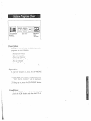
Description
Programming
Use; to prohibit selected extensions from making long distance calls.
Toll restriction can help eliminate telephone
abuse and contribute to controlling telephone
costs.
There are four service of classes available for
each extension.
1
I
Service Class Selections
I
1. Dial (II).
“TOLL RESTRICTION”
2. Press the NEXT button.
“ENTER EXT NO” will be displayed.
3. Press the NEXT button.
“11: CLASS 1” will be displayed and “1”
will blink.
\ 1
Denied
1
1 all calls
2.
toil calls,
‘. local calls
will be displayed.
I
4. Repeatpressiitg the SELECT button until the
desired class is displayed.
international
calls
5. Press the MEMORY button.
The LCD will stop blinking.
international calls,
any calls other than
specific area-code
programmed
international
toll calls
calls,
‘For Service Class 3, up to 10 area codes can be
selected for use in toll dialing (See “Toll
Restriction-Area
Code Selection” on page
3-21).
3-19
6. Repeat steps 3 to 5, to program
ment on the other extensions.
the assign-
7. To return to the initial program
the END b&n.
mode, press
Conditions
When you start the programming from step 1,
you may dial the desired extension number
instead of the NEXT button at step 3.
@The PREV button allows you to go to the
previous e.utension for displaying the service
class assignment.
l In some areas a “1” is needed before dialing
tht area code for long distance call. If your
area does not need to dial a “I”,
the
Programmable Toll Prefix should be set to
“WITHOUT
1’.
Refer to “Programmable
Toll Prefix” page
l
3-22.
Example:
l
To prohibit
international calls on extension 13
but allow local and toll calls enter.
[ll]
[NEXT]
[13] [SELECT]
[MEMORY].
ENDI
;I,
[NEXT] [NEXT] [NEXT] [NEXT]
[SELECT] [MEMORY] [END]
l
To prohibit international calls and toll calls on
extension 14 but to allow local calls.
[Ill [NEXT] [14] [SELECT]
[SELECT] [MEMORY](END]
[SELECT]
or
[ll]
[NEXT]
[NEXT]
[NEXT] [NEXT]
[NEXT] [SELECT] [SELECT] [SELECT]
[MEMORY] [END]
Programming
See page 6-15.
Table
,
:
:
:
:
:
,___________...._.......
area code with 3 digits
:
:
NOTSTORED
. . . . default (all memory locations)
;
:
(CLEAR)
:
-[12][NEXTI[*~][C][MEMORY][END]
+SELECT]-I
.---..--------------until the desired memory location number appears
Description
d
For Service Clnss 3 (see “Toll RestrictionClass Assignment” on pflge 3-19.), up to 10
area codes can be selected for use in toll dinling.
All clrea codes except those entered will be
denied.
All extensions progmmmed for Service Class
Selections 3 shall be assigned to the same orea
code selection plan.
5. Press the MEMORY
button.
@The memory indicator will be lit.
6. To advance to the .next memory
location
number, press the NEXT button.
To return to the previous memory location
number, press the PREV button.
To go to the desired memory location number, press SELECT button and the dial the
memory location number.
Programming
7. Repeat steps 4 to 6.
When Service Class 3 is programmed;
1. Dial (12).
“CLASS 3 AREA
ed.
8. To return to the initial program
the END button.
CODE”
will be display-
mode, press
Example:
To allow extension 12 to have access to New
York City and the entire state of New Jersey,
program the following.
New York City has 2 area codes 212, 718 and
New Jersey 201, 609.
Enter 212 into the memory locntion number
“OO”, 718 into “Ol”, 201 into “02” and 609 into
2. Press the NEXT button.
“ENTER
CODE NO.” will be displayed.
3. Dial (00 through
09) or press the NEXT
button.
Example:
When dialing (00) or pressing the NEXT
button.
aThe LCD will show “0O:NOT STORED”
wh?n nothing is stored in memory location
number “00”.
When area code 212 has been stored,
“00:212” will be displayed.
“03”.
STEP l...[ll]
-iNEXT]
[NEXT] [SELECT]
[SELECT] [MEMORY] [END]
STEP 2...[12][NEXTltNEXTl[212][MEMORY]
[NEXTj[718][MEMORY]
[NEXT)[201][MEMORY]
[NEXTj[609][MEMORY][END]
4. Dial the area code, with 3 digits.
@To erase a wronx entry, press the CLEAR
button.
Programming
See page 6-16.
3-21
Table -
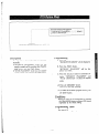
until the desired mode appears
[13] [NEXT] [SELECT] [MEMORY]
[END]
Programming
Description
Set to “WITH 1” for Toll Restriction in areas
where you are required to dial 1 to toll calls
(long distance).
1.
2.
Example:
You are required to insert a “1” before di@ling
the area code for long distance calls. .
1” in area where a “1”
will be displayed.
Press the NEXT button.
“WITH 1” will be displayed
and blink.
3.
Press the SELECT
button to alternate
between “WITHOUT
I” and ” WITH 1”
to select the desired mode.
4.
Press the MEMORY
button.
The LCD will stop blinking.
5.
To return to the initial program mode, press
the END button.
l-291 -348-7000
:---.area code
Set to “WITHOUT
not needed.
Dial (13).
“TOLL
PREFIX”
is
Programming
Table
See page 6-16.
*
:----until the desired extension number appears
[14] [NEXT] [NEi(T] [SELkCT]
[MEMORY]
[END]
t
or
[l4] [NEXT] [AB] [SELECT] [MEMORY]
7
‘AB=[%]:
[END]
to assign the same on all 16 extensions
Conditions
Description
Through programming, you can select of which
extensions may dial an Operator Call.
To deny all dialing that starts from “O”, set to
DISABLE.
0 When you start the programming from step 1,
you may dial the desired extension number
instead of the NEXT button at step 3.
l The PREV button allows you to go to the
previous extension for displaying the operator
call selection.
*Operator call dialing can not be denied if
service class 1 of Toll Restriction is used.
Programming
1. Dial (14).
“OPERATOR
CALL”
will be displayed.
Example:
2. Press the NEXT button.
“ENTER EXT NO” will be displayed.
3. Press the NEXT button.
“11: ENABLE”
will be displayed
“ENABLE”
will blink.
0 To prohibit operator call on extensiotl I2
[14] [NEXT] 1121 [SELECT] [MEMORY] IEND]
and
Programming
4. Press the SELECT button, to alternate between ENABLE and DISABLE to select the
desired mode.
See page 6-l 6.
5. Press the MEMORY
button.
Tha LCD will stop blinking.
6. Repeat steps 3 to 5, to program
ment of the other extensions.
the assign-
7. To return to the initial program mode, press
the END button.
3-23
Table
......:....._________________________
Description
Conditiorts
@Directory assistance dialing can not deny
service class 1 and 2 of Toll Restriction.
Through programming,
you can select which
extensions may be dialed Directory Assistance
“411”. For to deny the directory assistance
dialing, set to RESTRICT.
n
Programming
1. Dial (1.5).
“DIRECTORY
Example:
o To prohibit
ASSIST” will be displayed.
2. Press NEXT button.
“NO RESTRICT”
will be displayed
blink,
[15][NEXT][SELECT][MEMORY][END]
and
Programming
See page 6-16.
3. Press the SELECT button to alternate between “NO RESTRICT” and “RESTRICT”
to select the desired mode.
4. Press the MEMORY
button.
The LCD will stop blinking.
5. To return to the initial program
the END button.
directory assistance.
mode press
3-24
Table
J
;----------------.u,Iril the desired extension number appears
.;-w.‘-- until the desired mbde appears
AUTq.$NS,WER
. .. . . . . 1 . . . default (iili6
+f&r; gNs~,ji~~. ,-: .:
,>;:,,-.
i
: : ) .Y: : ,: :
[16] [NEXT] [NEXT]
t
[:;I
[SELECT]
[NEXT] [ABI [SELECT]
[MEMORY][END]
i
to assign the same on all 16 extensions
Description
Conditions
By programming either automatic or manual
answering can be set. The auto mode allows the
user to answer incoming outside calls simply by
lifting the handset, while if programmed to the
manual mode, the user must lift the handset and
press the flashing CO button.
e When you start the programming from step 1,
you may dial the desired extension number
instead of the NEXT button at step 3.
*The PREV button allows you to go to the
previous extension for displaying the automatic answering selection.
Examples:
l AUT0
Programming
MODE”
will be displayed,
ANSWER
mode on the extension 11
[16] [NEXT]
[I 11 [MEMORY] [END]
,3:]
[NEXT]
[NEXT]
*MANUAL
I2
2. Press the NEXT button.
“ENTER EXT NO” will be displayed.
ANSWER
[16] [NEXT]
[MEMORY][ENDl
mode on the extension
[12] [SELECT]
[MEMORY]
[END1
3. Press the NEXT button.
“11: AUTO ANSWER”
will be displayed
and “AUTO”
will blink.
&I
[NEXT] [NEXT]
[MEMORY] [END]
4. Press the SELECT button to alternate between AUTO
ANSWER
and
MAN
ANSWER to select the desired mode.
Programming
See page 6-16.
5. Press the MEMORY
button.
The LCD will stop blinking.
6. Repeat steps 3 to 5, to program the mode
selection of the other extensions.
7. To return to the initial program
the END button.
_I,‘.,
[MEMORY][END]
‘~.-~-~-~~~---.~.~-~..-~AB=[%]:
I. Dial (IS).
“CO ANSWER
exte&is)
mode, press
3-25
Table
[NEXT]
[SELECT]
;~~---.~~~~~
until the desired CO number
;;]
appears
[NEXT] [A] [A... D] [MEMORY][END]
._________._____.___.._____...
A=[*]:
to assigll the same on all 6 CO’s
i
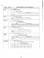
Description
If the system,
6. Repeat steps 3 to 5 to program
CO’s of the KX-T61610.
(KX-T61610)
is installed
behind a host PBX, the host PBX may require
a pause time to access Central Office Lines. This
feature enables the host PBX to automatically
pause via programming
the outward dialin
!:
access codes of the host PBX.
each of the
7. To return to the initial program mode, press
the END button.
Conditions
0 When you start the programming from step 1,
you
may diai the desired CO number instead
of the NEXT button at step 3.
l The PREV button allows you to go to the
previous CO for displaying the host PBX
access codes assignment.
Programming
1. Dial (17).
“HOST PBX ACCESS”
will be displayed.
2. Press the NEXT button.
“ENTER CO NO” will be displayed.
Example:
@Access codes 81, 82, 83, 9 on CO1 =
1171 WEXJ-1 VI WI [,I WI Ll P31 [,I Pl
3. Press the NEXT button.
*The
LCD
will show “COl:
NOT
STORED” when nothing is stored in COI.
When the outside access codes 81, 82 has
been stored, “CO1:81, 82” will be displayed.
[MEMORY]
[MEMORY]
See page 6-16.
button.
3-26
Ll WI
[END]
Programming
4. Enter vp to four outward access codes each
with a maximum of 2 digits, punctuating
each code with the r;l button.
l To erase a wrong entry, press the CL EAR
button.
5. Press the MEMORY
[END]
or
V71 [NEXT1 [NEXT] Pll
Table-3
Ll F331 LI PI
.
:-----------.1&l the desired extension number appears
[18] [NEXT] INEkT] [SE<ECT] [MEMYRY]
[END]
or
[18] [NEXT] [ABI [SELECT] [MEMORY]
[END]
--~---~.~--.~--~~.~~~~~~~
AB=[$]:
to assign thesame on all16 extensions
i
Description
Conditions
When you start the programming from step 1,
you may dial the desired extension number
instead of the NEXT button at step 3.
OThe PREV button allows you to go to the
previous extension for displaying the preferred
CO line assignment.
When any itlcoming ctrlls from the Central Office
are recei\*ed at the same time, you can receive the
call on the preferred CO line first.
l
Programming
I. Dial (18).
“PREFERRED
CO”
will be displayed.
Programming Table
Seepage 6-17.
2. Press the NEXT button.
“ENTER
EXT NO” will be displayed.
3. Press the NEXT button.
“II:
. . . . ‘9 will be displayed
It. .
” will blink.
l
and
l
4. Repeat pressing the SELECT button until the
desired CO number is displayed.
5. Press the MEMORY
button.
The LCD will stop blinking.
6. Repeat steps 3 to 5, to program
ment of the other extensions.
7. To return to the initial program
the END button.
the assignmode, press
3-27
_
,___.......____until the desired extension number appears
;..............
.until the desired mode appears
EX-OFF, CO-OFF. . . . default (all 2,$ extensidns)
EX-ON, CO-OFF
.,. ,’ ;
EX-OFF,‘CO-ON
EX-ON, CO-ON
~--~..~~--.-..~~.~~..~~-----~
AB=[*]:
to assign thesame on all 16 extensions
Description
5. Press the MEMORY
button.
The LCD will stop blinking.
During a conversation, a call waiting tone will
be heard when a third party on an outside line
or intercom calls you.
Call waiting tone can be removed or add!d at
customer’s request.
Set to “ON” for call waiting.
6. Repeat steps 3 to 5, to program
ment of the other extensions.
the assign-
7. To return to the initial program mode, press
the END button.
Programming
1. Dial (19).
“CALL WAITING”
Conditions
e When you start the programming from step 1,
you may dial the desired extension number
instead of the NEXT button at step 3.
@The PREV button allows you to go to the
previous extension for displaying the call
waiting selection.
will be displayed.
2. Press the NEXT button.
“ENTER EXT NO” will be displayed.
3. Press the NEXT
“11: EX-OFF,
and “EX-OFF,
button.
CO-OFF” will be displayed
CO-OFF” will blink.
4. Repeat pressing the SELECT
desired mode is displayed.
Programming
See page 6-17.
button until the
3-28
Table
-
. . .._..........._._.._ until the desired extension number appears
.I
.- dial the CO number
(none). . . . . default (all 16 extensi&ns)
.’
.I
-~-
l
l
.-.a,
l
AI
[20][NEXT][NEXT][A...F][MEMORY][END]
1
or
1
[20][NEXT][AB][A..
T
.F][MEMORY][END]
Description
The ringing start time can be delayed on a
designated extension(s) when an incoming call
is received from the CO.
The CO line(s) that you want to delay the ring
start titne can be selected through the programming. “Delayed Ringing Count Selection”
page 3-30 should be set.
1. Dial (20).
“DELAY
RING CO”
will be displayed.
2. Press the NEXT button.
“ENTER EXT NO” will be displayed.
3. Press the NEXT
“11: CO 8 8
and ”
l
l
7. To return to the initial program
the END button.
mode, press
Conditions
0 When you start the programming from step P,
you may dial the desired extension number
instead of the NEXT button at step 3.
Programming
l
6. Repeat 3 to 5, to program the assignment of
the other extensions.
l
l
l
l
button.
” will be displayed
” will blink.
l
l
l
4. Dial the CO numbers to be entered.
The desired combination of CO will be
displayed.
To prohibit dialing, press the CLEAR
button instead of CO number.
“11: CO . . . . . . . . . . ” will be displayed.
5. Press the MEMORY
button.
The LCD will stop blinking.
eThe PREV button allows you to go to the
previous extension for displaying the delayed
ringing assignment.
Programming
See page 6-17.
Table ,
.._..........__.....__._____ until the desired mode appears
.
AFTER 1 RING’;
. . I.. . . . I.. . II. :.y;-fL: .default
: ,. :;&
: ..’
.
i
[21][NEXT][SEI LIECT][MEMORY][END]
Programming
Description
After you select the CO lines that you want to
delay the ring start time, select the desired delay
ring count. Refer to “Delayed Ringing Assignmerit” page 3-29.
1. Dial (21).
“DELAY
RING
played.
COUNT”
will
be dis-
2. Press the NEXT button.
“AFTER 2 RINGS” will be displayed and
will blink.
3. Repeat pressing the SELECT button until the
desired mode is displayed.
:I
4. Press the MEMORY
button.
The LCD will stop blinking.
5. To return to the initial program mode, press
the END button.
Programming
See page 6-17.
3-30
Table
,.........__ unril the desired extension number
appears
,‘r.‘::
~___________..
-..:: _“.! .. ‘until. the desired mode appears
T0.N.E CALL. . . . . . . . . . default (all 16 extensions)
[1VOICE CALL
[22] [NEXT]
@&
[SELiCT]
t
r”:;] [NEXT]
[MEMORY][ENDl
I
[AB] [SELECT] [MEMORY]
[END]
Conditions
Description
When you start the programming frotn step 1,
you may dial the desired extension number
instead of the NEXT button at step 3.
l The PREV button allows you to go to rhe
previous extension for displaying the alerting
mode.
The inrercotn alerting mode (tone alertinglvoice
alerting) ar a receiving extension can be selected
rhrough programming.
TONE. . Tone alerting (ringing) sound at the
recei\*itlg esrension.
VOICE.. . Voice alerrittg instead of Tone alerting
is heat-d rhrough rhe speaker on the
receit.itig extension.
l
Example:
l VOICE CALL on the extension 13
[22] [NEXT] [13] [SELECT] [MEMORY]
Prograrnrnirzg
WDI
1. Dial (22).
“INTCOM
CALL MODE” will be displayed.
2. Press the NEXT burron.
“ENTER EXT NO” will be displayed.
3. Press the NEXT button.
“11: TONE CALL”
will be displayed and
“TONE”
will blink.
4. Press rhe SELECT button lo al!ernare between TONE CALL and VOICE CALL 10
select rhe desired mode.
5. Press the MEMORY
button.
-The LCD will stop blinking.
6. Repear sreps 3 10 5 to program rhe call mode
of rhe other extensions.
7. To
return
the END
to the initial program
mode,
Prograkning
See page 6-17.
press
burron.
3-31
Table
I----.ut~til the desired extension number
appears
I
:
until the &sired combination appears
D-PHONE 1,2 . . . . . . . . default (all 16 extensions)
D-PHONE 1
D-PHONE 2
(deny the ringing)
j
D-PHONE.
i------
1
[23] [NEXT] F
;3]
l
[SELECT]
[NEXT] [AB] [SELECT]
l
[MEM,ORY][END]
[MEMORY] [END]
,________________.__.____
AB=[G+]: to assign the same on all 16 extensions
[l I]: on extension 11
[26]: on extension 26
Description
Conditions
When you start the programming from step 1,
you may dial the desired extension number
instead of the NEXT burton at step 3.
*The PREV button allows you to go lo the
previous extension for displaying rhe doorphone assignment.
Allows each extension to be programme’ fl for
receiving calls from up to 2 doorphones.
(Doorphone is an option.)
l
Programming
1. Dial (23).
“DOOR PHONE
RCV”
will be displayed.
Example:
*To allow extension 12 to receive from
PHONE 2
2. Press the NEXT button.
“ENTER EXT NO” will be displayed.
[23] [NEXT] [12] [SELECT] [SELECT]
[MEMORY] [END]
3. Press the NEXT button.
“11: D-PHONE 1, 2” will be displayed and
“1, 2” will blink.
Programming
4. Repeat pressing the SELECT button until the
desired combination of doorphones (which
are to be connected to that extension) is
displayed.
See page 6-l 7.
5. Press the- MEMORY
button.
The LCD will stop blinking.
6. Repeat steps 3 to 5, to program the combination of the other extensions.
7. To return to the initial program mode, press
the END button.
3-32
Table
*
D-
---.-----.rrnril the desired exrension number
[24] [NEXT] [NE m] [A...Dl
t
or
1241 [NEXT]
[MEM,ORY]
[AB] [A.. .D] [MEMORY]
appears
[END]
[END]
AB=[*]:
to assign thesame on all 16 extensions
Description
6. Repeat steps 3 10 5, to program
Pertnits an extension user fo answer othet
ringing telephones, provided that they are in the
same pickup group.
the assign.
men1 of fhe other exretisions.
7. To relrcrti lo the initial program
the Eh’D burron.
mode, press
Programming
1. Dial (24).
“PICKUP
Conditions
GROUP”
peach extension may belong to more than one
pickup group, up to four, or tnay nof belong to
a group.
l When you start the programming
from step 1,
you may dial the desired extension numbet
instead of the NEXT button at step 3.
.The PREV buuon allows you IO go fo rhe
previous extension for displaying rhe pickup
group assignment.
*
will be displayed.
2. Press rhe NEXT burron.
“ENTER
EXT NO” will be displayed.
3. Press rhe NEXT burton.
“11: PKG: 1” will be displayed and “1” will
blink. This means that extension 11 belongs
to pickup group 1.
4. Dial the pickup group number (1 through 4)
to be entered.
The desired combination
of pickup group
will be displayed.
To -be out of any groups, press the
1 CLEAR button instead of group number.
Examples:
l extension 14.. Jickup
Group 2
[24][NEXT][14][2][MEMORY][END]
*extension 15...Pickup Group 3
[24](NEXTj[15][3][MEMORY][END]
5. Press the MEMORY
button.
The LCD will stop blinking.
Programming
See page 6-18.
a
3-33
Table
_ -
j____.__.____......
until the desired extension number appears
-“.‘--.-‘~.---‘-~“.“..
1
-.:
until the desired mode appears -.OPTION. . . . . . . :. .(. . ;‘. default
/
[*5][NEXT]pipsELECT][MEMyY][END]
OY
[25][NEXT][AB][SELECT][MEMORY][END]
7
to assign the same on all 16 extensions
Description
This feature gives each message of the SMDR
an account code of the called or calling party. ..
This feature has two modes “FORCED”
and
“OPTION”.
In the “FORCED”
mode, the
account code must be entered every time extension user dials.
In the “OPTION”
mode, the account code may
be entered when a record is needed. Refer to
“Account Code” page 4-25.
5. Press the MEMORY
button.
The LCD will stop blinking.
6. Repeat steps 3 to 5, to program
code of the other extensions.
the account
7. To return to the initial program
the END button.
mode, press
Conditions
Programming
When yore start the programming from step 1,
you may dial the desired extension number
instead of the NEXT button at step 3.
*The PREV button allows you to go to the
previous extension for displaying the account
code input mode.
l
1. Dial (25).
“ACCOUNT
ed.
CODE MOD”
will be display-
2. Press the NEXT button.
“ENTER EXT NO” will be displayed.
3. ,?ress the NEXT button.
“11: OPTION”
will be displayed
the “OPTION”
will blink.
and
4. Press the SELECT button to alternate between OPTION and FORCED to select the
desired mode.
Programming
See page 6-18.
Table
-I
.__._.....__.____.._~-.~.~~....
until the desired time appears
‘. ‘.. ..
I INSTANTLY
. . . : default
5s AFTER DIAL
CIOS AFTER DIAL
[26] [NEXT] [SELECT]
[MEMORY)[END]
Description
Example:
10 seconds after the dialing
=[26] (NEXT] [SELECT] [MEMORY]
The duration time of the conversation is displayed.
Program the start time of the timer.
oInstantly after the CO line is captured.
05 seconds after the dialing
*IO seconds after the dialing
Programming
See page 6-18.
Programming
1 s Dial (26).
l “DlJRAT-TIME
played.
COUNT”
will
be dis-
2. Press the NEXT button.
~“‘5s AFTER DIAL”
will be displayed and
blink.
3. Repeat pressing the SELECT
desired time (INSTANTLY,
DIAL,
10s AFTER DIAL)
button until the
5s AFTER
is displayed.
4. Press the MEMORY
button.
The LCD will stop blinking.
5. To return to the initial program
the END button.
mode, press
3-35
Table
‘.
[END]
Description
SMDR is a cost saving feature that records on a printer a record of all incoming
following information
is provided on the printout.
The SMDR will print out the security code of the long distance service. (MCI,
and outgoing
SPRINT
calls. The
etc.)
NOTE:
When plugging a printer into the KY-T61610 make sure that the printer power is off.
Select the SMDR Communication Parameters, System Data Dump and SMDR IncominglOutgoing
for proper operation.
Selection
Example of print
Date
4120187
: : :
: : :. year
: :
: :
: L..... day
Time
Ext.
CO
Dial Number
8:00 AM
26
6
l-201 -234-5678
i
:
Duration
00:00’30”
: : .
: : :
: : :.- second
: :
.: :. . . . . .. . minute
tailed
party
co
number
Code
0123
:--..-account code
>
i_________..__
hour
. . . .. . . . . month
F......extension
l When you have an incoming call, the printer will print <<incoming>>.
l When “=”
appears in the Dial Number, the previous number of ‘<=I’ indicates the line access number of the
Host PBX.
h .
l When “X”
appears in front of the Time, this means the time that the call is transferred.
::‘i
SMDR Printer Format Selection
(Carriage return for a new line)
until the desired code appears
[*7][NEXT][sEL~cT][MEMORY]
1
(Baud rate)
until the desired baud rate appears
-
[NEXTj[SELECT][MEMORY]-t
Proceed to page 3-37.
3-36
J
(Word length)
Continued from page 3-36.
;............................‘.....”’..---’
[NEXT][SEiECT][MEMORY]
,~I
until the desired length appears.
1
I
(Parity)
. . . .. until the desired mode appears
_____.______.._____.___.........-.. .default
-
[NEXT][SE&CT][MEMORY]
(Stop bit length)
i
.___________........:. .. . . .. . .. .. . . y\ until the desired mode appears
- [NEXT][SE&CT][MEMORY]
1
(Page length)
,____.______.______.~.......................
AB=[4]
[&
(lines)
. . ; . default
(Skip perforation)
AB=[O] (line). . ; : default
L-m-
(NEXT]m[MEMORY][END]
A word length code indicates how many bits
compose a character.
A new line code indicates what type of code is
needed for the print head on a printer to move
the first character position on the next line.
CR+LF
when “CR+ LF” is required from a
printer.
CR
when “CR” is required from a printer.
7 BITS (when 7 bits are required.)
8 BITS (when 8 bits are required.)
i
A stop bit length code indicates the end of a bit
string which composes a character.
CR= Carriage Return
LF= Line Feed.
1 BIT:
when one bit is required for end
detection.
2 BITS:
when two bits are required for end
detection.
A baud rate code indicates the data transmission
speed from the system to a printer.
110
150
300
600
1200
2400
4800
9600
B (when
B (when
B (when
B (when
B (when
B (when
B (when
B (when
110 baud
150 baud
300 baud
600 baud
1200 baud
2400 baud
4800 baud
9600 baud
is required.)
is required.)
is required.)
is required.)
is required.)
is required.)
is required.)
is required.)
,4,
.
The page length may be selected to position a
title and data on each page.
A page length code indicates the number of lines
per page.
A title will be printed on the first 3 lines of each
page.
The default value is the same as that of the
Panasonic data terminal, KX-D491OD, KX04911, KX-D4920 etc, except baud rate.
<I
STANDARD CONTINUOUS PAPER (11 inches)
A parity code indicates what type of parity is
used to detect an error in a string of bits
composing a character.
we
NONE:
when an error checking function is
not required from a printer.
MARK: when a Mark is required from a
printer.
SPACE: when a Space is required from a
printer.
EVEN:
when an Even is required from a
printer.
when an Odd is required from a
ODD:
printer.
length
-~... ___. . . __. _- - . . - - 0. .
0
0
0
0
0
t
machine
0 perforations
I
skip
perforation
0
0
0
0
0
0
To print data, page length must be longer than
skip perforation by 4 or more liries.
3-38
12. Repeat pressing the SELECT button until
the desired parity code is displayed.
The skip perforation code indicates the number
of lines to be skipped. When the print head
reaches the line designated, the print head
moves to the top position of the next page.
13. Press the MEMORY
button.
The LCD will stop blinking.
14. Press the NEXT
button.
“STOP BIT: IBIT” will be displayed and
the “IBIT’
will blink.
0 (print head does not skip.)
1 (print head skips the last line.)
2 (print head skips the last 2 lines.)
15. Press the SELECT button to alternate
between 1BIT and ZBITS to select the
desired mode.
9; (print head skips the last 95 lines.)
16. Press the MEMORY
button.
The LCD will stop blinking.
17. Press the NEXT
Programming
I. Dial (27).
“SMDR PARAMETERS”
played.
“PAGE
will
be dis-
button.
66” will be displayed
will blink.
LENGTH:
and the “66”
18. Dial (4 through 99) for the page length
entry.
2. Press the NEXT button.
“NL-CODE:
CR-l-LF” will be displayed
and “CR+LF”
will blink.
19. Press the MEMORY
button.
The LCD will stop blinking.
3. Press the SELECT
button to alternate
between CR-?-LF and CR to select the
desired mode.
20. Press the NEXT button.
“SKIP PERF: 0” will be displayed and
the “0” will blink.
4. Press the MEMORY
button.
The LCD will stop blinking.
21. Dial (0 through 95) for the skip perforation code entry.
5. Press the NEXT button.
“BAUD RATE: 1200B” will be displayed
and the “1200B” will blink.
22. Press the MEMORY
button.
The LCD will stop blinking.
6. Repeat pressing the SELECT
button until
the desired baud rate is displayed.
7. Press the MEMORY
button.
The LCD will stop blinking.
23. To return to the initial program mode, press
the END button.
Programming Table
See page 6-18.
8. Press the NEXT button.
“WORD
LENGT: 7BITS” will be displayed and the “7BIT.S” will blink.
9. Press the SELECT
between 7BITS
-desired mode.
button to alternate
and 8BITS to select the
10. Press the MEMORY
The LCD
button.
will stop blinking.
11. Press the NEXT button.
“PARITY:
MARK” will be displayed and
the “MARK”
will blink.
Conditions
_’
~To return to the previous mode, press the
PREV button instead of the NEXT button.
Conditions
The following
EIA SIGNALS:
combinations
are disallowed.
stop bit length
Frame Ground (FG);
Connects to the unit frame and the earth ground
conductor of the AC power cord.
Transmitted Data (TXD); . . . . . . . . . . . . . . (output)
Conveys signals from the unit to the printer. A
“MARK”
condition is held unless data or BREAK
signals are being transmitted.
Received Data (RXD); . . . . . . . . . . . . . . . . . . . . (input)
Conveys signals from the printer.
If any of the above disallowed combinations are
selected, “INPUT ERROR” will be displayed.
Press the NEXT button and then repeat the
procedure of programming.
The pin conJguration of EZA (RS-232C) connector is
as follows.
1
2
FG
TXD
Frame Ground
Transmitted
Data
AA
BA
101
103
3
4
RXD
RTS
Received Data
Request To
Send
BB
CA
104
105
5
6
CTS
DSR
Clear To Send
Data Set Ready
CB
CC
106
107
.7
8
SG
DCD
Signal Ground
Data Carrier
Detect
AB
CF
102
109
20
.’ DTR
Data Terminal
Ready
CD
108.2
Request To Send (RTS); . . . _ . . . . . . . . . . . . (output)
This lead is held ON whenever DSR is ON.
Clear To Send (CTS); . . . . . . . . . . . . . . . . . . (input)
An ON condition of circuit CTS indicates that the
printer is. ready to receive data frotn the unit.
The unit does not attempt to transfer data or receive
data when circuit CTS is OFF.
Data Set Ready (DSR); . . . . . . . . . . . . . . . . . . (input)
An ON condition of circuit DSR indicates the
Iprinter is ready.
‘Circuit DSR ON does not indicate that communication has been established with the printer.
Signal Ground (SG);
Connects to the DC ground
interface signal.
of the unit for all
Data Terminal Ready (DTR) . _ . . . . . . . . . . (output)
This signal line is turned ON by the unit to indicate
that it is ON LINE.
Circuit DTR ON does not indicate that communication has been established with the? printer.
It is switched OFF when the unit is OFF LINE.
Data Carrier Defect (DCD) . . . . . . . . . . . . . . . . (input)
The ON condition is an indication to data terminal
(DTE) that the carrier si@al is being received.
A
*STOP OUTPUT
j----.----------------.--until the STOP OUTPUTappears
[28][NEXT][SELiCT][MEMORY][END]
*SYSTEM PARA
aSPEED DIAL
*ALL PARA (Master)
until desired data dump mode appears
SYSTEM PARA . . . . . . . . . . . . . . . . . . . . default
co
PARA
EXT
PARA
SPEED DIAL
ALL
PARA
: STOP OUTPUT
[28][NEXT][SE
t
*CO PARA (Outside)
...__..__.._............ until the CO PARA appears
8 .
.
.
I
.
A=[*]:
[l]:
.
to assign the same on all 6 CO’s
on COI
[6]: onCO6
I
[28][NEXT][SELkT][MEMORY]&END]
l EXT PARA
._-....___._________
until the EXT PARA appears
[28] [NEXT][SEl
3-41
I
Description
Five separate printouts are available.
They are (1) System parameters (2) CO parameters (3) Extension parameters (4) Speed dial
(5) All parameters (master)
System parameters
DaylNight
Area codes of class-3
Toll prefix
Directory Assistance
Delay Ring count
Duration time count
SMDR parameters
Duration log
Auto hold alarm time
Hold recall time
Transfer recall time
Ext-paging access tone
Secret speed dialing
D TMF receiver selection
Door phone receive extension
Pickup group assignments
DSS operation mode
DSS console set
Delayed Ringing CO
Intercom call mode
Account code input mode
Automatic CO hunting
Do not disturb
Call forwarding
Data line security
Dial callpickup deny
Feature button assignments
CO button assignments
DSS button assignments (KX-T30830 only)
<< DSS Console Items>>
Feature burton assignments
DSS button assignments
n
CO parameters
Connection
Dial mode
Host PBX access code
Hookswitch flash time
Disconnect time
CPC Detection
Extension parameters
q (When the KX-T61630, KX-T61620,
KX- T&650, KX- T30830, KX- T30820 or
KX-T30850 is connected at extension.)
Telephone type
Outgoing CO DaylNight
Incoming CO Day/Night
Toll restriction
Operator Call
CO answer mode
Incoming preferred CO
Call waiting
H (When thestandard telephone or DSS Console
is connected at extension)
J
Telephone type
DSS console connection
Outgoing CO DaylNight
Incoming CO Day/Night
Toll restriction
Operator call
Incoming preferred CO
Call waiting
Delayed ringing CO
Account code input mode
Pickup dial
Do not disturb
Call forwarding
Data line security
Dial call pickup deny
Speed dial
Speed access codes (00 through 99) in
which phone numbers are stored may be
printed.
All parameters (master)
System parameters
CO parameters
Extension parameters
Speed dial
-k
Operation
When the CO Parameter is printed;
To stop the printout;
1. Dial
1. Dial
(28).
2. Press the NEXT
2. Press the NEXT
button.
3. Repeat pressing the SELECT button
STOP OUTPUT is displayed.
4. Press the MEMORY
“STOP PRINTING
:’
‘:.
(28).
button.
3. Repeat
pressing the SELECT
“CO PARA” is displayed.
until
4. Press the MEMORY
“ENTER CO NO”
button.
!!” will be displayed.
button until the
button.
is displayed.
5. Dial the CO number.
SMDR printer will print out.
“PRINTING
NOW’ will be displayed.
When the System Parameters, Speed dial or All
Parameters is printed.
I. Dial (28).
“SYSTEM DATA OUT” will be displayed.
6. To print the other CO parameter, press the
SELECT button and then dial the CO
number.
2. Press the NEXT button.
“MENU:
SYSTEM PARA”
will be displayed and “SYSTEM PARA” will blink.
When the Extension
1. Dial
3. Repeatpressing the SELECT button until the
desired data dump mode is displayed.
(28).
2. Press
4. Press the MEMORY
button.
The LCD will stop blinking.
Parameter is printed;
the NEXT
button.
3. Repeat pressing the SELECT button until rlze
“EXT PARA” is displayed.
5. Repeat step 2 to 4, to print the other data
dumps.
4. Press the MEMORY
“ENTER EXT NO”
button.
is displayed.
5. Dial the extension number.
SMDR printer will print out.
“PRINTING
NOW” will be displayed.
6. To print the other extension parameter, press
the SELECT button and then dial the exterzsion number.
After completing printing,
mode;
1. Press
the END
button.
Programming Table
See page 6-19. -’
3-43
to return to the initial
until the desired mode appears
Description
It is possible to print eithe; outgoing out&de
calls, incoming outside calls or both.
OUTGOING:
OUTGOING:
INCOMING:
IMCOMING:
Programming
n
ON.. . to print
outside
OFF.. . to stop
ON...
to print
outside
OFF... to stop
outgoing
calls
printiq
becoming
calls
prirzting
1. Dial (29).
..
“DURATION
LOG”
will be displayed.
2. Press the NEXT button.
“OUTGOING:
ON” will be displayed alld
the “ON” will blink.
3. Press the SELECT button to alternate between the “ON” and “OFF” to select the
desired mode.
4. Press the MEMORY
button.
The LCD will stop blinking.
5. Press the NEXT button.
“INCOMING:
ON” will be displayed
the “ON” will blink.
arid
6. Press the SELECT button to alternate between “ON” and “OFF” to select the desired
mode.
-L
7’. Press the MEMORY
button.
The LCD will stop blink@.
8. To return to the initial program
the END button.
Programming
See page
6-19.
mode, press
Table
-
_
‘.
:
.
until the desired time appears
[30] [NEXT] [SE<ECT] [MEMORY] [END]
Description
A tone itldication will be heard at the holding
extension to remind the user that he still has a
call on hold.
The reminder will sound after 3 minutes but can
be changed.
There are 9 choices ranging from (1) minute to
(9).
4. Press the MEMORY
button.
The LCD will stop blinking.
5. To return to the initial program
the END button.
mode, press
Conditions
The hold time reminder is activated, even if the
hold recall time set is programmed
to “DISABLE”.
Example:
4 minutes= [30] [NEXT] [SELECT]
[MEMORY] [END]
Progmmming
1. Dial (30).
“AUTO HOLD
ed.
2. Press the NEXT
“TIME: 3 MIN”
will blink.
ALARM”
will be display-
Programming
See page 6-20.
button.
will be displayed and “3”
3. Repeat pressing the SELECT
desired time is displayed.
brcttotl until the
Table
until the desired time appears ’
30 SEC-- ; , . . . . ‘: . . default
1 MIN
;
.,., .,
1.5 MIN
._.., ;
-:
2DISABLE
MJN .:
i.‘. ‘- -~
:
[31] [NEXT ‘1[SELECT] [MEMORY] [END]
Example:
I.5 minutes:
Description
When the handset of the holding extension is
replaced back on call, you may have the
automatic hold recall after the desired time
elapses.
The hold recall titne set can be removed ot
added at the customer’s request.
[31] [NEXT] [SELECT]
[SELECT] [MEMORY] [END]
Programming
See page 6-20.
Programming
1. Dial (31).
“HOLD
RECALL
ed.
TIME”
will be dis lavR -
2. Press the NEXT button.
“TIME:
30 SEC” will be displayed
“30 SEC” will blink.
and
3. Repeat pressing the SELECT button until the
desired time (30 SEC, 1 MIN, 1.5 MIN, 2
MIN, DISABLE)
is displayed.
4. Press the MEMORY
button.
The LCD will stop blinking.
5. To return to the initial program
the END button.
mode, press
3-46
Table
I-““““-~‘.~‘“‘“-.-‘-’
[32] [NEXT] [SELECT] [MEMORY]
until the,&sired mode appt&
[END]
Example:
Description
To elitninare
The acktloj\)leti,oe four rhar is heard nfrer nccessitlg Ilie external pagitlg cat1 be retnol~ed ot
added ciI rlie cusIot?ier’s request.
rhe paging access tone.
[32] [NEXT] [SELECT]
.j
:i ;
.!.,
?!
..:
Programming Table
:
,.
.:
5,:.
-:
-:
Programming
1. Dial (32).
“EXT-PAG
eci.
See page 6-20.
ACIS-TONE”
will be display-
2. Press the NEXT butrorl,
“ENABLE”
will be displayed
and blitzk.
3. Press the SELECT burron to altertrare befweetl ENA B L E arid DISA B LE IO selecr rile
desired mode.
4. Press the MEMORY
burrotl.
The LCD will stop blinking.
5. To return to rile initial program mode. press
tile END burton.
3-47
[MEMORY][END]
~~~-~~~--~~~--~~---~~.~~--~-~
il
until the desired mode appears
[33] [NEXT] [SELECT] [MEMORY]
[END]
3escription
When you dial on an outside line by speed
dialing, the dialed number can be kept secret by
not being displayed.
(The dialed number will not be displayed on the
LCD of the KX-T6163O/KX-T30830.)
h
Programming
1.
2.
Dial (33).
“SECRET
played.
SPEEDDIAL”
Press NEXT button.
“NO SECRET”
will
blink.
will
be dis-
be displayed
and
3.
Press the SELECT
button to alternate
between “NO SECRET” and “SECRET”
to select the desired mode.
4.
Press the MEMORY
button.
The LCD will stop blinking.
5.
To return to the initial program
the END button.
Programming
See page 6-20.
Table
*
mode, press
:.-.......-.----- until the desired CO number
appears
until the desiredflash timing appears
:.
[34] [NEXT] [NEI(T] [SELECT]
or
[MEMYRY]
[END]
[34] [NEXT] [A] [SELECT] [MEMORY] [END]
I~~~~~~~~~-._.._.~-~~-~-~---~~
A=[*]:
to assign the same on all 6 CO’s
--/-
Description
Conditions
The timing of the hookswitch flash signal must
be within the requirements from your Central
Office.
There are three choices available 0.3, 0.6 or 0.9
second.
0 When you start the programming from step I,
you may dial the desired CO number instead
of the NEXT button at step 3.
OThe PREV button allows you to go to the
previous CO for displaying the hookswitch
flash timing.
Example:
l O.3 set on all 6 CO=
.
[34] [NEXT] [++I [SELECT] [SELECT] [MEMORY]
Programming
1. Dial (34).
“FLASH
TIME
SET”
[END1
will be displayed.
2. Press the NEXT button.
“ENTER
CO NO” will be displayed.
3. Press the NEXT button.
“CO 1: 600 MS” will
“600 MS” will blink.
Programming
See page 6-20.
be displayed
4. Repeat pressing the SELECT
desired value is displayed.
and
button until the
5. Press the MEMORY
button.
The LCD will stop blinking.
6. Repeat
steps 3 to 5, to set the hookswitch
timing of the other CO’s.
7. To return to the initial program
the END button.
mode, press
3-49
Table
,_._._..__._until the desired CO number appears
[35] [NEXT] ,Ni+XT] [SXECT]
;]
[MEkjORY][END]
[NEXT] -[A] [SELECT] [MEMORY][END]
‘--..-...-_..-.--..-.--.....
A=[*]:
to
assign
the
Same
Description
011 all
6 CO’s
6. Repeat steps 3 to 5, to set the disconnect time
for the other CO’s.
A certain amount of time is needed for an
outside call to be released, this is necessary so
that a new call may be aitempted after disconnecting with the previous call.
There are two choices available, 1.5 and JO
7. To return to the initial program mode, press
the END button.
seconds.
The time you select must be longer than the
requirements from your Central Office or host
PBX.
Conditions
When you start the programming from step 1,
you may dial the desired CO number instead
of the NEXT button at step 3.
@The PREV button allows you to go to the
previous CO for displaying the disconnect
time.
l
Programming
I. Dial (35).
“DISCONNECT
TIME”
will be displayed.
Example:
l 4.0 see on all 6 CO=
[35] [NEXT] [++I [SELECT]
2. Press the NEXT button.
“ENTER
CO NO” will be displayed.
3. Press the NEXT button.
“CO 1: 1.5 SEC” will be displayed
“1.5 SEC” will blink.
Programming
See page 6-20.
and
4. Press the SELECT button to alternate between 1.5 set and 4.0 sec.
.,.
.
5. Press the MEMORY
button.
The LCD will stop blinking.
3-50
Table
[MEMORY] [END]
I....-.until the desired CO number appears
[36][NEXT][NEXT][SELECTj[MEMPRYJ[END]
f
I
or
[36] [NEXT] [A] [SELECT] [MEMORY] [END]
--7-
6. Repeat steps 3 to 5, to program
ment of the other CO’s.
Description
To detect that an outside party has hung up and
then terminate the outside (after a conversation,
conference etc.) a CPC signal is needed.
CPC signal detection can be removed or added
at customer’s request.
7. To return to the initial program
the END button.
DETECTION”
When you start the programming from step 1,
you may dial the desired CO number instead
of the NEXT button at step 3.
~The PREV button allows you to go to the
previous CO for displaying the calling party
control signal selection.
l
will be displayed.
2. Press the NEXT button.
“ENTER
CO NO” will be displayed.
3. Press the NEXT button.
“CO I: ENABLE”
will be displayed
“ENABLE”
will blink.
mode, press
Conditions
Programming
1. Dial (36).
“CPC
the assign-
Programming
See page 6-20.
and
4. Press the SELECT button, to alternate between ENABLE and DISABLE to select the
desired mode.
5. Press the MEMORY
button.
The LCD will stop blinking.
3-51
Table
until the desired mode appears .”
[37] [NEXT] [%
ciZCT] [MEMORY]
[END]
Programming
Description
1. Dial (37).
“DSS BUTTON
Outside calls can be transferred to any extension
manually.
@“WITHOUT
TRANSFER”
mode you can
transfer outside call by pressing the TRANSFER button and then DSS button.
..
l “WITH TRANSFER” mode you can trqsfer
outside call by only pressing the DSS button.
.,
MODE”
will be displayed.
2. Press the NEXT button.
“WITHOUT
TRANSFER”
played and blink.
will
be dis-
3. Press the SELECT button to alternate between “WITHOUT
TRANSFER”
and
“WITH TRANSFER”
to select the desired
mode.
4. Press the MEMORY
button.
The LCD will stop blinking.
5. To return to the initial program mode, press
the END button.
Conditions
@Intercom calls can be transferred by pressing
the TRANSFER button and then DSS button
regardless of the mode setting.
Programming
See page 6-21.
3-52
Table
-%
_
until the desired mode ajjtars
[39] [NEXT] [SELiECT] [MEMORY]
[END]
Programming
Description
1. Dial (39).
“XFER RECALL
When a call is transferred to any extension, if
other extension does not receive the transferred
call within 30 seconds, the call will return to
you.
The time may be changed to 2 minutes.
TIME”
will be displayed.
2. Press NEXT button.
“30 SEC” will be displayed
and blink.
3. Press the SELECT button to alternate between “30 SEC” and “2 MIN” to select the
desired mode.
4. Press the MEMORY
button.
The LCD will stop blinking.
5. To return to the initial program
the END button.
Programming
See page 6-21.
3-53
Table
mode, press
.-----.---------.until the desired extension number appears
,_______._..........-~.until the desired modi appears ‘I’,:.: >f;-FEATURE KEY.. ; . . . . :. default’(all16
FWDIDND KEY :
[40] [NEXT] [NiXT]
;]
[SEIECT]
[MEM,ORY] [END]
[NEXT] [AB] [SELECT] [MEMORY]
.. . .._.___. ..___ .__ _.
[END]
__ __________.___
to assign
Description
the
saf?le
on
all
16
extensions
4. Press the SELECT button to alternate between FEATURE
KEY and FWDIDND
KEY to select the desired mode.
3 programmable feature (Fl, I??, F3) buttons
are provided with the proprietary teleph nes,
P
KX-T61650 and KX-T30850, and only .“F3”
button can be changed from programmable
feature button to call forwarding (see page 4-35
for operation)ldo not disturb (see page 4-37)i
account code (see page 4-25) button.
“FEATURE
KEY” mode...
programmable feature function
“FWDIDND
KEY” mode.. .
call forwarding/do
not disturblaccount
code function
5. Press the MEMORY
button.
The LCD will stop blinking.
6. To return to the initial program mode, press
the END button.
7. Repeat steps 1 to 6, to program call
forwardingldo
not disturblaccount code button of the other extensions.
Conditions
Programming
1, Dial (40).
“M3IFWD SELECTION”
..I.. ...
extensions)
@You may repeat pressing the NEXT button
until the extension number to which the
KX-T61650 or KX-T308.50 is connected is
displayed instead of the dialing the extension
number at step 3.
*The PREV button allows you to go to the
previous extensio%’ for displaying the M3l
FWD selection.
will be displayed.
2. Press the NEXT button.
“ENTER EXT NO” will be displayed.
3. Dial the -extension number to which the
KX-T61650 or KX-T30850 is connected.
Example:
When dialing 20, the LCD will show
‘20:FEATURE
KEY” and the “FEATURE
KEY” will blink.
Programming
Table
See page 6-21.
3-54
-
DETAILED FEATURE LIESCRIPTION AND OPERAYONE KXJ61630,
_-_ TELEPl
----.~
~_
TION FOR EMSS PROPRIETA.RY
3'
KX-T61620-
KY-T61650.
-', ---_
- -.- - - - I KX-T3Oi
-~~~..
- 930,KX-T30820,KX-T 0850)
TO operate this system, after making program changes, set the System
(Electronic Modular Switching System) to the SET position.
When the unit is unused, the Liquid
Crystal Display will show the month, day and rhe present time.
Hands-free
Using the Handset
LIFTTHE
HANDSET
DIALTHE
EXTENSION
NUMBER
(llthrough26)
HANGUP
TALK
*Your muy press tllc ICM
Intercom
.lCh!t-@CO -Central
Office
PRESS
"SP-PHONE"
butroll irlsread of the first
DIALTHE
EXTENSION
NUMBER
(11 through 26)
SP-PHONE
TALK
PRESS
3P-PHONE-
bulton.
Conditions
Description
Srarrfon IO starioll dialing withill rhe KX-T61610
system.
Operation
Using the handset
1. Lift fhe handset.
2. Dial the extension number
(11 through 26).
3. Srarr talking
4. Hang up upon completiorz of the conversation.
Hands-free
1. Press the SP-PHONE
Program Switch located on the KX-T61610
or ICM
2. Dial the extension number
burton.
(11 through 26).
3. Starr ralkirlg
4:Press- the SP-PHONE
button again
completion of the conversation.
after
*When a called party has the KX-T616301
KX-T30830
equipped
with an LCD,
the
extension number of the calling party will be
displayed on the LCD of the called party.
0 The extension number of the culling party will
be displayed on the LCD of the KY-T616301
KX- T30830.
0 The ICM indicator
the unit.
will be lit green while using
o The KX-T616iO or KX-T3OS50 will not fmction for hands-free mode.
H Individual
Line Access
Using the Handset
cl
WXY
-9..
LIFTTHEHANDSET
ORPRESS
"SP-PHONE"
DIAL"9"
DIALTHEPHONE
NUMBER
WAITFORTHE
DIALTONE
TALK
C.O.
I
I
LIFTTHE
HANDSET
PRESS
"CO"
WAITFORTHE
C.O. DIALTONE
DIALTHEPHONE
TALK
HANGUP
HANGUPOR
PRESS "SP-PHONE"
Hands-free
Description
Each extension can auromatically
CO
(Central
Office)
line
KX-T61610.
select an idle
within
the
PRESS
“CO”
WAITFORTHE
C.O. DIALTONE
DIALTHEPHONE
NUMBER
Operation
1. Lift rhe handset or press the SP-PH d bE
burton.
TALK
i
Description
2. Dial (9).
Dial tone from CO (Central Office) will be
heard.
l The CO indicator
will -be lit green at yout
extension and lit red at other extensions.
3. Dial the phone
PRESS
"SP-PHONE"
AtI?
of the 6 CO’s may be directly selected.
Operation
Using Ihe handset
I. Lift the handset.
2. Press rke CO buttotl.
Dial totie from CO will be heard.
nutnber.
3. Dial the phone nutnber.
4. Start talking.
5. Hang up.
4. Starr talking.
5. Hang up or press the SP-PHONE button
upon corizpletion of the conversalion.
Hands-free
1. Press rhe CO button.
Dial tone from
Conditions
q The 9 dialed, will be displayed on the LCD
of the KX-T6163O/KX-T30830
and you will
hear -following.
*Dial tone from the CO: indicates that the CO
line is captured.
@Busy tone: indicates that the six CO lines are
busy.
l Reorder tone: indicares that lhe exrettsion is
denied access to an outside
CO will be heard.
2. Dial the phone number.
3. Start talking.
-’
4. Press rhe SP-PHONE
button.
The phone number dialed will be dispjayed on the
LCD of the KX-T61630lKX-T30830.
.You can not use rhe CO button whose indicator
is lit (red) as this CO line is use.
@The KX-T61650 or KX-T30850 will not funcrior
for hands-free mode.
l
4-2
q Individual
Line Access
m. pJ
LIFTTHEHANDSET
ORPRESS
"SP-PHONE"
PRESS
"AUTO"
DIAL THESPEED
ACCESSCODE
(OOthrough99)
L
LIFTTHEHANDSET
ORPRESS
"SP-PHONE"
DlAl "8"
DIALTHECO
NUMBER
(1 through 6)
Description
There are 100 memory locations of system speed
dialing available.
DIALTONE
NUMBER
Operation
OR PRESS
"SP-PHONE"
1. Lift the handset or press [he SP-PHONE
burron.
Description
Any of the 6 CO lines may be selected by dial
access.
2. Press the AUTO
3. Dial the speed access code.
Operation
sl You may press the CO butIon to select rhe
CO line directly after lifting the handser or
press the SP-PHONE button.
1. Lift the handset or press the SP-PHONE
butron.
’ 2. Dial (8) and the CO number (I through 6).
Dial tone from the CO (Central Office) will
be heard.
3. Dial the phone number.
4. Start ralking.
5. Hang up or press the SP-PHONE
bulfotl.
Conditions
0 The phone number dialed will be displayed on
the LCD of the KX-T6163O/KX-T30830.
0 Individual line access codes
Dial 81 for CO I
Dial 82 for CO 2
Dial 83 for CO 3
Dial 84 for CO 4
Dial 8.5 for CO 5
Dial 86 for CO 6
El Each extension can access a new CO line
withoztt hanging up.
While having B conversation,
PRESS
ANOTHER-CO"
*The original conversation will be terminated
and a new CO line will be accessed.
button.
Condition
*The dialed number will be displayed on the
LCD of the KX-T6163O/KX-T30830.
oContinuous use of speed dialing is possible.
ex. [AUTO] (01 [O] [AUTO] [O] [ll
Chaining together two or more memory locations.
l
Combinations
of speed dialing, one touch
dialing and manual dialing is possible.
Programming
Be sure the handset is in the cradle and the SP-PHONE
or MONITOR
*Set the MEMORY
switch of the KX-T61630,
KX-T61620,
KX-T61650,
KX-T30850 to “PROGRAM”.
button is OFF.
KX-T30830,
KX-T30820
l
w To Erase after Programming
q Storage
PHONE
NUMBER
"PROGRAMMABLE
FEATURE"
"PROGRAMMABLE
FEATURE"
'-MEMORY"
the MEMORY
PRESS
"CLEAR(TRANSFER)"
INSTEADOF
"MEMORY"
"MEMORY"
button is used as the CLEAR
After programming
all the numbers,
switch‘to
the “SET’
return
position.
Dialing
W To Correct an Error while Pro~rammitq
El
"CLEAR
(TRANSFER)"
eThe TRANSFER
button.
@You may dial 81 through 86 instead of 9.
9 . . . . . . . . Each extension can automatically select an idle CO line.
81 through 86. Each extension can select a
designated CO line.
19 or 81 through 86 must be dialed for storage. 1
TRANSFER
bAfter pressing the CLEAR
button, reprogram the carrect number.
oThe TRANSFER button is
used as the CLEAR button.
1
f,
I
LIFTTHE HANDSET
ORPRESS
"SP-PHONE"
1
1
"PRESS
PROGRAMMABLE
FEATURE"
q You may press the CO button to select the
CO line directly after lifting the handset ot
press the SP-PHONE button.
II To Change a Stored Number
Repeat “Storage”
S To Conjirm
or
above.
a Stored Number
Repeat programming
same station.
the same number
I
into the
When the MEMORY button is pressed, a beep will
be heard.
*two beeps . . .. . . . storage is correct
*onebeep
. . . . . . storage is incorrect
Repeat the procedure of programming.
4-4
Description
Dialing
There are 12 memory locations for automatic
dialing available. Up to 32 digits can be srored
into each of the 12 tnetnory locarions. Pushing
[he “*Jc”, “#O, “-3s)
“FLASH”
or “PAUSE”
button counrs as I digit.
l For your convenience, program
pri\*are phone
numbers into the KX-T61630,
KX-T61620,
KX- T61650,
KX- T30830,
KX- T30820 or
KX-T308JO.
1. Lift rhe handset or press rhe SP-PHONE
butron.
2. Press a programmable
burton.
~You may press the CO burton to select the
CO line direcriy after lifting rhe handset ot
press the SP-PHONE button.
Programming
Conditions
Be sure rhe handset is in [he cradle and rhe
SP-PHONE or MONITOR
button is OFF.
aUse the ” 0 “, or ” a ” button for scrolling
the display from side to side.
l The dialed phone number will be displa-ved on
the LCD of the KX-T61630/KX-T30830.
l The combinations
of speed dialing. one-touch
dialing and manual dialing is possible.
eThe line access number (9 or 81 through 86)
should be stored.
l Continuous use of tine rouch dialing is possible.
Example:
1. Set the MEMORY switch to “PROGRAM”.
“PROGRAM
MODE”
will be displayed.
2. Press a programtnabie feafllre button.
The LCD will show “MOI: IVOTSTORED”
when nothing is stored in the programmable
feature button “01”.
When automatic line access nutnber 9 and the
phone number 123-4.56-7890 has been stored,
“11101: -123-456-7890”
will be displayed.
Wll WI
In this case, programmable feature brrrton
“02” should not include the line access
number.
l When
dialing, the pause is aulomatically
entered after line access number (9 or 81
rhrough 86).
*Features that can be accessed by using the
dialing button 01~0 can be programmed
into
memory.
Refer to “One Touch Access for System
Fearures” page 4-23.
3. Enter [he line access nunlbtr.
9: automatic line access tti~tnbcr
81: line access number of CO I
82: line access tlumber of CO 2
S3: line access nrlmber of CO 3
84: line access number of CO 4
85: line access number of CO 5
86: line access number of CO 6
4. Enter rhe phone number.
l You
may etirer putic~1rrrtiotl.s drlring N
phone number.
The SNR button is used as the “-” button.
l To erase a wrong entry, press the CLEAR
buuon.
The TRANSFER
button is used as the
CLEAR burton.
5. Press the MEMORY
blrtrott.
The MEMORY
indicator will be iir.
6. Repear steps 2 lo 5, to program
programmable
fearfrrre buttons.
feature
Examples:
Automatic line access number 9 and phone
nurnber 123-4567 into the programmable
feature button “01”.
Progranitning
Set the MEMORY
switch to “PROGRAM” position.
[Ol] [9] [123-45671 [MEMORY]
Return the MEMORY
switch to “SET’
position.
-Dialing
Lift the handset.
Dial [Ol]
on orhet
7. After programming
all Ihe numbers, return
the MEMORY swirch to rhe “SET” position.
The MEMORY
indicator will go out.
l
4-5
You may. press the CO button fo select the CO
line directly after lifting the handset.
Description
Calling doorphone 1
LIFTTHEHANDSET
ORPRESS
.'SP-PHONE"
I
Calling
DlAL"31"
door-phone 2
A disbrzcbve dial tone will be heard from he
hnrldset if rhe esrmsion user has prel~iously
acfivared a special fearure.
Operation
WAITFORTHE
CONFIRMATION
TONEAND
THENTALK.
None
Conditions
There are two types of dial tones.
Dial lolIe I: ordirlary dial tone
I
I
LIFTTHEHANDSET
ORPRESS
"SP-PHONE"
DlAL"32"
WAITFORTHE
CONFlRMAllON
TONEAND
THENTALK
I
call be
Operation
Dialiq
fo rhe doorphoties
1. Lifr rhe handser or press rhe SP-PHONE
burrou.
I
WBR
2. Dial 131) for calling doorphoile 1.
Dial (32) for calling doorphone 2..
“DOOR I” or “DOOR 2” will be displayed.
3.
Wait for the confirmation
talking.
4. Haq
ripor
/L-----J
I set
tone and then start
up or press rhe SP-PHONE button
completion of /he cotiversation.
Conditions
l
I
Dial Iolle 2: ,c,hcn any of the following
tlo’es is activared:
Description
Up to two doorphones (KX-T30865)
connected to the KX-T61610.
I
The features, for imtance, hold, tramfer and
so otl, cati not be activated by the doorphone.
4-A
Do tlot Disturb.
Dial Call PickLrp Deny
Call Forwarding.
Dam Line Security.
Background Music
I
I
I
I
I
I
fea-
I
-
WL”n
Setting
honr.irin
..
&or outssrde (trunk) calls
HEARABUSY
TONE
CONFIRMATIONS
TONE OFZBEEPS
WILLBE HEARD
HANGUPOR
PRESS
"SP-PHONE"
--
r0rc1lLfor ca,nIJ-ot~
.,I..
LIFTTHE HANDSET
DRPRESS
"SP-PHDNE"
Whet7 i17terc0171
For inierc&n calls
EXTENSION
NUMBER
(11 through 26)
n
HEARABUSY
TONE
CO:NFlRMATlON
TONE OFZBEEPS
WILLBEHEARD
PRESS
"SP-PHONE"
YOUWILL
IiEARTHECO
DIALTONE
C(llh
LITTTHEHANDSET
ORPRESS
"SP-PHONE"
YDUWILLHEARTHE
RING BACKTONE
--
-__I
__.
Conditions
e Liftitlg the hculdset (or pressitlg tile SPPHONE button) dltritlg the cramp-on tnode
will cause the cflmp-otl feature to be cat~cellecl.
If rile itlrercotn extensiotr or olrtside line you
hnve dic~lecl is busy, y0l.i will be uutotnaricnlly
called buck whet! the estensiotl or the outside
line beconIes free llsitlg this futicriotl.
This feuiire is ciiso kilorvti ns uitnp-011.
eAtr estetlsiom muy be the recipient of more
thrltl one cdl back busy, the call backs will be
executed in the order of their nrrivd.
Qpemtion
@If o call buck is not rcns\vered nt the originatitlg
es;etlsion tvithitl IO secotzcls, the call buck will
be catlcelled.
Setting
1. Lift rhe hntidset or press the SP-PHONE
buttotl.
2. For intercom calls, dial tlie extensiotl tzrrtnber.
For olttside cnlls, press the CO button.
.;j
.:
::j
.:Ii/
,:’
!!!
T,i
.:,:
:j
3..Dial
.(6) crfier a busy tone is heard.
Recall for camp-on
4. Wait for the cotIJirt7iatioti tone.
“CAMP ON CO” or “CAMP ON EXT”
will be displayed.
5. f-lang__L.? or press the SP-PHONE
buttori.
Whet1 %eariYly a recall for camp-on;
Lift rhe liatldset or press the SP-PHONE
buttoil.
e When using an intercom call, you will
hear the iing back totle.
er?Yhen using an outside call, you will
hear the CQ dial tone.
-
‘,
4-7
L
--
YOUWILL
HEARABUSY
TONE
DIALTHE
EXTENSION
NUMGER
LIFiTHEHANDSET
ORPRESS
"SP-PHONE"
OIAL "1"
ANDWALTFOR
AN ANSWER
PRESS
"LNR"
Description
Descriptior2
The last photle tlilttiber dialed 011 atz outgoing
call (CO line) cat1 be redialetl.
If rhe estemiot7 you hnvi: dialed is busy. yorr calf
irlfortn that exretrsion [hat morher itrtercottl cali
is waiting by three beeps.
For use of [his feature, the other extension is
requited to be set for this feature beforehand in
the KX-T61610.
Opercrtion
\
2. Lift [he hadset
burrott.
or press the SP-PHONE
2. Press the LJJR buttotl.
Operation
1.
Lifr
the
hcitlclset
or
pwss
the
SP-PHO/~E
b11ttot1.
::.
eYou may press the CO brltrotz to select the CO
line directly lifter lifting the hatdset or press.
the SP-PHONE or MONITOR
button.
2. Dial the extension nutnber.
Conditions
*Up to 32 digits ccttl be siorcd utzcl redialed.
3. When you will hear a busy lotze, dial (1)
and wait for m mswer.
Plid7itig
rlie
“W’
“#”
0s I digit.
iz+
Whet2 cullitlg or while
ttlotle, pressitlg [he LNR
medial to operfice after
C011tlt.s
Conditions
0 To answer your signal, see “Call Waiting” 011
page 4-l 6.
*If the other party is usitq data equipment, you
may not be able to use this feature.
“If b busy lone is heard ufter dialing 1, it
indicates that &e other party has not beet1 ser
with this feature.
Or
“PA
USE”
itz the cotlversalion
buttotz will cause the
about 3 secotids.
--
-
4-8
blllfotl
5
L
_,’
Setting
TO
cancel
,
L.I
LIFT THE
HANDSET
OperatiolYz
,.,Lift rhe hnttdser
PRESS “AIJTO ANS”
(INDICATOR WILL
BE LIT)
PRESS
“SP-PHONE”
f’RESS “AUTO ANS”
(INDICATOR WILL
GO OUT)
Description
or press llze SP-PHONE
Allows extension user I0 cmswer 1117ititercom
call in the au~omnlic hntlds-free mode rvitliollr
iirly operaiion when receiving ~112
itilerconi call.
brluotl.
@?Vhen he “‘Autotnntic At7swering Selecrion”
fetrhrre has been selected lo the L’mcirluc~l”
mode in the KX-T6.1610 nttd an orltsicle call is
received, ‘you tnwf lift the handset and rhen
press the CO button whose indicator
is
flashing (red color) quickly.
1. For settitrg, press the AUTO AN.7 butt&n.
The AUTO ANS indicator will be lit.
2. Fbr ctrncelitrGotl, pres.r tile A UT0 ANS
bllrton ngnin.
The AUTO A NS indicetor will go oL[t.
* Wlzetl receiving cite itzlercom cdl, yore mny
press rhe ICM button whose indicator is
fhhing
quickly nnrl talk. (.Hcttlds-free mode)
Description
e?-his feature is required to be set bejorelratlcl
while the unit is not in use.
@When receiving nn outside call, you may press
the CO button whose indicator is f&a&zing red
quickly and talk. (Hcmds-free mode)
QThe KX-TG16.50 or KX-T30550
riots for Automntic Atuwer.
“If nny incoming calls from the Central Office
ore received nt Ihe snme time except preferred
C.0 line, you must lift the handset and then
press the ‘CO butlon whose indicator
is
flushing (red color) quickly.
tvill not furic-
.
Co,nditions
“If CLcnll reaches tfzrough the CO line to which
the CO&e number is not assigned, the ICM
indicntor wiil flash quickly. And the CO call
cnn be received by pressing the ICM or ,the
SP-PHONE butron or lifting rhe handser.
.
-
4-9
L
LIFT THE HANDSET
ORPRESS
“SP-PHONE”
DIAL "40"
LIFF THE HANDSET
OH PRESS
“SP-PHONE”
Description
DIAL “4”
OIALTHE RINGING
EXTENSION
NUMBER
(11 through 26)
Descriptio 11
An exrension user cm mswer ally ritlgrtlg
esiension within their O~II pickup group.
An estemioti ,tln), atmver (111itlconliq call flm~
is ringitlg at mother e.vtcs/rsiotl regardless of
the picklrp group.
Operation
Operation
1. Lift rhe hflndsel or press Ihe SP-PHONE
bulton.
1. Lifi
the hntldsct
or pwss
the SPyP/lIOtVE
brrrtot1.
2. Did (40) cd
,:-‘Lb
is
wait for the confirmation
tone.
2. Dial
(4) c7rrrlhen rile fstclrsioti Il[t&er
(I [
dlroligh 26) (it wliicll 1~11 is t-ijlgitlg.
3. Wait for cotlfirttici~io~l totle aud then stnrt
talking.
3. Start talking.
Conditions
,’
QDial Call Pickrip will work for incortlillg cnlls
(intercom, ourside and doorphone) bllr \vi/l
not w0rk for ccirnp-on recall and hold recall.
@If a ringing
group or is
iTlOde,
then
through the
exterzsion is oulsicle the pickup
in rhe dial call pickup denied
0 reorder tone will be heard,
use of this feature.
6,ReIer to “Dial Call Pickup Group Assigtrmetrr
on page 3-33.
SDirrl Call Pickup cm use with the present call
placec! on hold.
--
Conditions
.
Qlr is possible
fl.rsigtled
pickup
f0
CitlSI~‘C’t’
Cii11.S
oul.ride
yoiil
grorrp.
QDirecteti Grill Pickup co11 i~se with Illc present
ctrll placed 011 hold.
Ex&ple:
Mr Broll:1l’s esktisiotr tlrr,~fber is 16.
He is ti01t’ alit of the ofjice.
Mark r-ecei1,e.sthe ~011 i,l.src~nd of Mr. Bro\vtl
with rhe telephone on his desk (exteruiotl 15).
J
:
To retrieve a parked call at any extension
-2:.
LIFT THE
HANDSET
OR PRESS
“SP-PHONE”
DIAL “5”
DIAL PARKED
EXTENSION
NUMBER
---
--
Description
Allo~vs any estensiotz user to retrieve a call
(intercom or outside) on hold at any extetuiotz.
Operation
Whet1 atI intercom or outside call is otz hold.
1. Lift rite handset or press the SP-PHONE
button at atly estettsion.
Exatnple:
Mark is ralkitzg’with extensiotz 15 0t1 his desk,
and theta moves to atlother rootn placing the call
on hold.
He resumes the conversatiotl using anolher
estensioti.
Pressthe HOLD
kmg
r1p
Nllci
biiliotr.
tl1en
go
2. Dial (5) atld rhe esretuiotl number of the
phone oti which rhe cnll is placed 011 hold.
(Connecrion is tlow tnade with the party who
lvas on holcl.)
3. Wait for the cot+w7c~tion tot!e and then start
talking.
Even when several outside calls areplaced on
hold sitnultaneously,
you can retrieve the
desired outside call from another extension as
following.
I. Dial
(53).
2. Dial
the CO aumber.
(1 through
6).
Conditions
@Call park retrieving is possible regardless of
the handset position of the phone which has
placed t!je
- ._call on hold.
@If rhe exretlsiotl thar JJOL~ want to retrieve the
call park has several calls on hold, ottly the
last call ot1 hold will be retrieved.
and the
exremiotl
-.
Description
To answer c1 doorphone
-.
A differetlr ritlgitig pnttern is rmd to distitiglrish
intercom cdls from itzcotnitlg outside cdls.
Operation
LIFT THE
HANDSET
Notie
PRESS
“SP-PHONE”
Conditions
Operation
I.
L.ift lhe hmdset
burror].
A~itonlotic ritlg back for the canlp on feature
will ritlg dijreretltly from the ritlgitlg OH ititercoin,
outside, md doorphot~e cczl1.r.
or press rhe SP-PHONE
Conditions
Incottling
recall)
*If culls from cloorphotzes clre tlot nrmverecl
lvithitz I5 secotlds, the ccllls dl be ccmcellcd.
@Ring jt-otn doorphone.
Itlrercotn
outside
calls (itzcluding
crtlls (itlcl~rcliq
ourside
itzlercotn hold recall)
fi
Ccich exretisiotl lrcts IO be progmmtned
fot
recei\+ng from doorphoties. See “Programtnnble Doorphotle”
otz pctge 3-32.
Doorphotle
calls
-
4-12
hold
L
.
To
place
a call
hold:
on
PRESS
To retrieve:
(Outside calls on hold)
ealt the holding extension
(Intercom call on hold)
@at the holding extension
I
CONFIRMATION
TONE OF'2
BEEPSWILL
BEHEARO
PRESS"C0"
PRESS
"KM"
@from atrother exrerisiotz
efronz another extension
PRESS"C0"
DIALTHE HOLOING
EXTENSION
NUMBER
OlAL"5"
. ..
uescrlptlon
,P wispy.I
1J you
wanf
wait,
com
;. Calls
sions.
to
r
leave
Conditiorzs
yottr
phone
rtnattet7ded
*An Intercorn hold can be activated on one
extension only.
@An Outside call hold can be activated on six
CO’S.
.If‘a
call is on hold for more that7 30 mitiutes,
a
hold t&
retninder will be sounded and the
call will be terminated automatically.
A hold time reminder is sounded #trough the
built-it1 speaker of the extension.
~Calls on hold will be recalled ei(her after
30 seconds,
1 minule,
I rtiinufe
and
30 seconds or 2 rtlitlutes, once handset is
replaced (or the SP-PHONE
buttot
is
pressed).
If hold recall time is sef to “DISABLE”,
if wiil
not be recalled.
Refer to “Hold Recall Time Ser” on page 3-46.
bril
the caller you are itr conversalion with to
call hold may be used. Outside or intercalls may be placed on hold.
on hold can be released by other exten-
Operation
1. Y011 are in conversation
with at1 outside
or internal party.
2. Press the HOLD
burrott.
The indicator of CO or ICM button lvhich is
on hold will flash slowly (green color).
The confirmarion
tone of 2 beeps will be
J1eai.d.
To Retrieve af tJle holding extension,
press the CO or ICM button @lashing green).
The indicator light will return to a steady
green.
To Retrieve fro,, artorller extension,
press
-the
CO bullon (&hit&
red).
or
dial (5) and then the extension (11 through
26) or CO (81 through 86) number of the
phone on which the call. was place2 on
hbld. - -
0 The hold rime reminder is activated, even if rhe
hold recall rime ser is proiratntned
to “DISABLE”.
@When lifting the handset (or press the SPPHONE button) :
before recal1ing.d.
dial tone will be heard
with the call on hold.
~-You tnay dial anotJ7er
phone number.
while recalling... Only the first call. on hold
will be released and etltered
into rhe cotiversnlion mode.
PI LABI
----AB=ll
yB=RI
-I
tkrotcgh 26 (extension)
tlzrough 86 (CO)
a,The green flashing indicator
extension will mm to red.
eRefer to “Call Park Retrieve”
aI the ‘held
-
on page 4-11.
4-13
L
‘-?Ti
-* 1J
- --
:t i
‘8
i,
‘!
:
.i
i
-
To place a call on exclusive hold:
To retrieve:
-
(Outside calls on hold)
(Intercom call on hold)
1
PRESS
"HOLD"
PRESS
AGAIN
PRESS
“CO”
PRESS
"KM"
Conditions
Description
An intercom or outside call placed on exclusive
hold can not be released by any extension other
than the phofle which has placed the call on
hold.
@An Intercom hold can be activated on one
extension only.
@Air Outside call hold can be activated on six
CO’S.
@Ifa call
i,.*2 Operation
‘-
1. You are in conversation
internal party.
with an outside or
.:.
2. Press the HOLD buttor!.
The indicator of CO or ICM bllttorz which is
on hold will flash slowly (greeti color).
A confirmation torte of 2 beeps will be heard.
3. Press the HOLD
button, again.
?;he indicator will flash in groups of 2 (green
color).
is on hold jor more thall 30 minutes, a
hold tinle reminder will be sounded, and the
call will be terminated automatically.
A hold time reminder is sounded through the
built-in speaker of the extension.
.:.; eCa1l.r otz hold will be recalled either after
30 seconds,
I rniriilte,
I niirlute
Lid
30 secorlds or 2 minutes, once handset is
replaced (or the SP-PHONE
button
is
pressed). If hold recall time set is set to
“DISABLE”,
will not be recalled. Refer to
“Hold Recall Time Set” on page 3-46.
0 The hold time reminder is activated, even if the
hold recall time set is’ programmed to “DISABLE”.
4. To retrieve, press the ICM button or the CO
button whose indicator is flashing in groups
of 2 (green coLor).
The indicator on the ICM or CO button will
return to a steady green.
*When lifting the handset (or press the SP.
PHONE button) :
before recalliq....A
dial tone will be heard
with the call on hold.
You mny dial another
phone number.
while recalling.. . OPlqiihe first call .on hold
wilM$?“released and entered
into the conversation mode.
.J
PRESS
“CONF”
CONSULT WITH
THE 2N0 PARTY
DIAL
2N0 PARTY
NUMBER’
PRESS
“CONF”
To ten&ate one caller and talk to the other caller.
elf bdth the confereflce parties are on the
outside:
Press the CO buttotl to talk to the desired
party.
DescriptiOn
Allolvs fo; rip to a three party conference,
(~-olttsidell-irisitle)
(I-outside/2-inside)
or (3inside).
elf both the conference parties are on the
extension:
Press the ICM button.
You will be connected to the first participant.
Opeiyation
1. Press the CONF
. party on hold.
button,
to place the first
“If
the conference parties are 0); the outside and
extension:
To talk to the outside party, press the CO
button.
To talk to the extension partyS press the ICM
button.
2. Dial the number of the second party.
If second party does not answer, press the
CO button of the outside party concerned, or
the ICM button to return to the first party.
3. Press the CONF button.
A conJirmation tone will be heard.
3 pflrty confesence is now established.
“CONF”
will be displayed.
@You may press the HOLD
the first CONF button.
To leave the other two parties on hold at the same
time.
Press the HOLD button.
eon case the other two parties are 011 the
extension, the other two parties can not be left
on hold.
button instead of
Conditions
-
.
oPre.~sing a CO blrtton b\:hich is 01.11 Of COll/k'l.e/ice, ~lllorvs you I0 esir from tile co~ijkreiice
mci 10 access an outside party and the 0d1el
parties to be connected together.
j,;
If [/le ot/7ep+urfirs tire ourside OIICS. Illi’)’ ClLL.‘-;
i
i
- c!isconnecteq&.& “’
If r/le orlier phrrics tire 011 the o~rtsitlc (lllcl
esreiisiori, Iliej~ are c0trileCId.
To terminate conference
Replace the handset or press the SP-PHONE
buttoil.
eThe other two parties will be directly conn-g&d together and can converse with each
-other’. -(Intercom calls and intercom to outside
are OK, outside to outside is not possible.)
~Pressirrg the ICM brlttotl :/‘)r corl,ferellce,
a(/o~.s yore to exit from the co~lferCIl(.C (lrlti to
access an intercom.
- L
n
1c
To terminate the original call and talk to the new caller.
-
WILL HEAR A
CALL WAITING
TONE
TALK
PRESS “CO” OR “ICM”
WHOSE INDICATOR
IS FLASHING
CIUICKLY
To place the original call on hold and talk to the new caller.
elf both original call and new call are intercom calls:
(The ICM indicator will change lighting intoflashing quickly when new call reaches.)
WILL HEAR A
CALL WAITING
TONE
PRESS
“HOLD”
CONSULT WITH
THE NEW CALLER
WH!LE THE
ORIGINAL CALL IS
ON HOLD
PRESS “ICM” TO
TERMINATE THE
2ND CALL AND TO
RETURN TO THE
ORIGINAL CALL
*If original call is CO call, and new call is CO call or intercom call:
or
If original call is intercom call and new call is CO ca’ll:
I
WILL HEAR A
CALL WAITING
TONE
PRESS
“HOLD”
PRESS “CO” OR “SM”
WHOSE INDICATOR‘
IS FLASHING
OUICKLY
I
PRESS “CO” or”lCM”
WHOSE
INOICATOR IS FLASHING SLOWLY TO
TERMINATE THE 2ND CALLAND TO
RETURN TO THE ORIGINAL CALL
ON HOLD
Description
3. Consult with the new caller.
4. Press the ICM button to terminate the second
call and to return to the original call.
Call-waiiing tone during a conversation indicates there is a new incoming CO line call or
Intercom call.
This feature is required to be set beforehand in
the KX-T61610.
For programming,
see page 3-28.
@Iforiginal
call is CO call, and new call is CO
call ‘or intercom call:
or
If original call is intercom call and new call is
co call:
1. You will hear. a call waiting tone.
2. Press the HOLD button for placing a
‘conversation on hold.
.
3. Press the CO or ICM button whose indicator
is f7ashing quickly.
4. Consult with the new caller.
5. Press the CO or ICM button whose indicator
is flashing slow&&-terminate
the.second call
and to return t?-&e original call.
Operation
To ierminate the original chll and talk tq the new
caller.
1. You will hear a call waiting tone (3 beeps).
2. Press the CO or ICM button whose indicator
is flashing quickly. The original call is now
terminated.
3. Start f&king.
_._._
To place-the ariginal call on hold and talk to’ the.
new caller.
“If both original call and new call are intercom
tails:
(Th‘e ICM indicator will chpnge lighting into’
flashing quickly when new call reaches.)
1. You will hear a call waiting tone (3 beeps).
2. Press the HOLD button for placing a conversation on hold.
Conditions
e/f a call
’
waiting tone is heard and the CO ot
ICM indicator does not flash, this tone
indicates a “call waiting tone by _ special
company service.
In this case, see “Call Waiting-Outside
Line” on page 4-24.
- -
4-16
To transfer after other extension answers
PRESS
“TRANSFER”
DIALTHE
EXTENSION
NUMBER
ANNOUNCE
AND WAIT
FOR AN
AljSWER
To transfer without announcing the other extension
HANG UP OR
PRESS
“SP-PHONE”
PRESS
“TRANSFER”
HANG UP OR
PRESS
“SP-PHONE”
DIAL THE
EXTENSION
NUMBER
To Retrieve the Call
if the other extension did not receive the transferred call within 30 seconds after the call has been
transferred, the call will return to ~0~1.In this case:
LIFTTHE HANDSET
OR PRESS
“SP-PHONE”
Description
Outside or intercom &lIs may be transferred
any extension manually.
TO change the party to whotn a call is transferred
before hanging up
Press the CO or ICM button whose indicator is
flashing slowly to retrieve the call, then repeat
the procedure of Call Transfer.
to
Operation
1. YOLL are engagecl in a call (outside or
intercom).
2. Press the TRANSFER
button.
3. Dial number of extension (11 through 26) to
which the call is transferred.
4. For, Unscreened call transfer, replace the
handset or press the SP-PHONE
button.
For Screened call transfer, wait for neb3 party
to answer and announce call, then replace
the handset or press the SP-PHONE button.
Conditions
8 Upon recall to the transferring exlension, if
call is not answered in 30 minutes it ,will be
/
terminated.
8 When busy, you may access the other extension by dialing 1.
a
Also you may return to the calling -party by
pressing the CO or ICM button whose indicator is flashing slowly (green color).
To retrieve the Call
If the,.o.tJer extension did not receive- the
transferred-call within 30 seconds after the call
has been transferred, the call will return to you,
In this case:
Press the CO or ICM button whose indicator is
flashing slowly or lift the handset.
oThe time that thea.!
returns to yowl when the. =?<
transferred call is not,.yeceived can be changed
y .“i
“F
30 se.conds into ‘2Y~,
minutes.
For changing, see page 3-53.
..
A 7-7
-
PRESS “HOLD”
TO PLACE 1ST
PARTY ON
HOLD
CONSULT WITH
THE 1 ST PARTY
CONSULT WITH
THE 2ND PARTY
DIAL 2ND
PARTY
PRESS “KM” OR “CO”
WHOSE INDICATOR IS
FLASHING SLOWLY
PRESS “HOLD”
TO PLACE THE
1ST PARTY ON
HOLD
PRESS “CO” OR “ICM”
WHOSE INDICATOR
iS.FLASHlNG SLOWLY
PRESS “HOLD”
TO PLACE THE
2NO PARTY ON
HOLD
CONSULT WITH
THE 2NO PARTY
,, Descriution
-:)
-.
Allotvs an
8. Press the ICM or CO button whose indicator is flashing
extension user to alternate between a
CO party and an Intercom party.
;:,
slowly.
9. Consult with the second party.
::
10. Repeat step 4 to 9.
Operation
1. Press the HOLD
party on hold.
button to place the first
Conditions
eTo release the call splitting mode, press the
CO or ICM button without pressing the
HOLD button.
Conversation will be terminated and call OH
hold will be returned to conversation.
2. Dial the second party.
3. Consult with the second party.
4. Press the HOLD
pariy on hold.
button to place the second
.
5. Press the CO dr ICM button whose indicator is flashing slowly.
6. Consult
with the first party.
7’. Press-the-HOLD
party on LoId.
button
to place the first
.
-
A 70
L
To access
PRESS
"HOLD"T0
PLACE
1STPARTY
ONHOLD
L-cc&d
.PRESS
"HOLD"T0
PLACE
ZNDPARTY
ONHOLD
.. :
T--i
CONSULT'.
WliHTHE
ZNDPARTY
2N0
PARTY
LIFTTHEHANDSET
dRPRESS
"SP-PHONE"
PRESS
"HOLD"T0
PLACE
ISTPARTY
ONHOLO
CONSULT
WITHTHE
1STPARTY
Description
Allows an extension user to alternate between
two intercom parties.
Operation
1. Press the HOLD
party on hold.
button
El Page will be heard
only from the built-in
speuker of KX-T61630,
KX- T61620, KX- T61650,
KX- T30830, KX-T30820
or KX-T30850.
Description
3. Consrtlt with the second pnrty.
Allows paging to ail extensions.
button to place the second
5. Consult with the first party.
6. Press the HOLD
WAITFORAN
ANSWER
ANOTALK
to pince the fir.rt
2. Dial the second party,
4.. Press the HOLD
party on hold.
PAGE
CONFIRMATION
TONEOFI BEEP
WILLBEHEARO
DIAL
button
to place the first
party on hold.
7. Repeat step 3 to 6.
Conditions
~To release the call spIittjng”mocle, press the
ICM button instead of the HOLD
button.
Conversation will be terminnted and call on
hold will be returned to conversation.
Operation
To accesspaging;
I. Lift the handset or press the SP-PHONE
button.
2. Dial (34) ~117~1 tvait for confirmation
tone
(one beep).
“PAGING
(ALL)”
will be displayed.
.
3. Start pnging.
4. Wait for an answer and talk.
%
Conditions 7
,,.
-.-L--;
-” .I:
aWhen an e,&nsion is in use, that extension z
cannot gain access to paging.
0 When any extension is using the paging (a!1
extensions, group or external), you camot
access
to paging.
--
0 access
ror pickup
‘0 access
group 1
LIFTTHEHANDSET
ORPRESS
"SP-PHONE"
DIAL
"35"
LlFT'iHEHANOSET
ORPRESS
"SP-PHONE"
CONFIRMATION
TONE
PAGE
PAGE
WAITFORAN
ANSWER
ANDTALK
CONFIRMATION
TONE
DlAL"33"
WAITFORCONFIRMATION
TONEANDTALK
f&i kage will be heard
from exrernal paging
equipmerft.
For pickup group 2:
At step 2 above, .d,ial36 instead of 35.
For pickup group 3:
At step 2 above, dial 37 instead of 3.5.
For pickup group 4:
A f step 2 above, dial 35 instead of 35.
Description
Allows access to external paging equipmenr.
@ Page will be heard onl})
from the built-in speaker
of KX-T61630,
KX-T61620, KX-T61650,
KX-T30830, KX-T30820
or KX-T30850.
Operation
To access external paging;
1. Lift rhe handset or press the S/‘-PHONE
button.
2. Dial (33) and wail for confirmation tone (one
beep}.
“EXTERNAL
PAGING” will be displayed.
3. Start paging.
When the page is answered, one beep will be
heard. Start talking.
Description
Allows paging to one of four groups.
Operution
To access paging;
1. Lift the handset or press the SP-PHONE
button.
2. Dial (35) for paging the pickup group 1.
Dial (36) for paging rhe pickup group 2.
Dial (37) for paging the pickup group 3.
Dial (38) for paging the pickup group 4.
OThe confirmation tone (one beep) will be
heard.
e”PAGING
(GRP l)“, “PAGING
(GRP
(GRP 3)” or “PAGING
4”, “PAGiNG
(GRP 4)” will be displayed.
Conditions
;If external paging access tone is set to “DISABLE”, confirmation tone will not be heard
after accesshg the external paging.
Refer to “Programmable
Exrernal
Access Torte” on page 3-47.
3. Starr paging.
4. Wait fey-hn
answer and talk.
Conditions
*When an extension is in use, that ex:tension
cannot gain access lo paging.
*Refer to “Dial Call Pickup Group Assignment” on page 3-33.
:
.
:
-
4-20
L
Paging
To transfer a call to the paged person
rbbl
WHILE HAVING
A CONVERSATtON
r---l
?o answer
I
DIAL
“34”
LtFt THE HANDSET
OR PRESS
“SP-PHONE”
“TRANSFER”
‘.
PAGE
WAtT FOR AN
ANSWER
DtAL
“43”
CONFlRMATtON
TONE
TALK
“SP-PHONE”
OYou may clial3.5, 36, 37, 35 or 33 instead of
34.
i
ji‘3
_
,...
Description
A page from the built-in speaker or external
paging equipment can be answered front atzy
extension.
Operation
To transfer a call to the paged person;
1. You are in conversalion.
2. Press the TRANSFER
3. Dial (34)
Dial (3.5)
Dial (36)
Dial (37)
Dial (38)
Dial (33)
8 Wait for
Operation
To answer paging;
bluron.
1. Lift rhe handset or press the SP-PHONE
buttotl.
for paging all extensions.
for paging group 1.
for paging group 2.
for paging group 3.
for pagitzg group 4.
for paging-external.
confirmation tone.
2. Dial (43) and wait for confirmation
beep).
3. Start talking.
4; Start paging.
Conditions
aIf a call and CO number has been.paged and
transferred, you may answer by pressing Gie
CO button whose number has been paged and
indicator is flashing slowly (red color), instead
of dialing 43.
5. Wait for an answer.
6. Hang up or press the SP-PHONE
button.
. . . ..-
-
._
tone (one
4-21
-
._’
To enable
DIAL "7511"
REPLACE THE
HANDSET
ORPRESS
"SP-PHONE"
DIAL "750~~"
3EPLACE THE
iANDSET
ORPRESS
"SP-PHONE"
LIFTTHEHANDSET
ORPRESS
"SP-PHONE"
WILLHEAR
MUSIC
I.
To cancel
LIFTTHEHANDSET
ORPRESS
"SP-PHONE"
Description
Conditions
.i Mu& from at7 extertlal source (e.g. radio) .catl
be listetled to on the built-in speaker of the
telephone.
Operation
To enable
’
8 Whet1 listening to the backgroutzd music, the
music \l-xill be interrupted by itlcomitlg calls,
lifting hatzdset or pressing the SP-PHONE
blltton. After completiotl of the cotlversatiotl
replacitlg the hatzdset back on the cradle or be
p~‘essitlg- of the SP-PHONE button, will resume the backgroud music.
1. Lift the hatldset or press the SP-PHONE
button.
2. Dial (751#).
Wait for cotifirmalion totie.
“BGM ON” will be displayed.
.
3. R&Aace’hcuzdset or press the SP-PHONE
button.
Music will be heard from the speaker.
To cancel
1. Lift the handset or press the SP-PHONE
buttou. ‘.---.w_
2. Dial (750#).
Wait for confirmation
“BGM
OFF”
lone.
will be displayed.
3. Place rhe hatldset back ot1 the cradle or press
the SP-PHONE
button.
Music will be stopped.
-
L
To enable
Be sure the SP-PHONE
indicator
is on.
PRESS
“MUTE”
@The. MUTE
indicator
To Program
Set the MEMORY
switch
of the
.KX-T61630,
KX-T61620,
KX-T61650,
KX-T30830, KX-T30820 or KX-T30850
to “PROGRAM”.
Example:
Paging All Extensions (Dial 34).
will flash.
To cancel
PRESS
“PROGRAMMk3LE
FEATURE”
DIAL “34”
PRESS
“MEMORY”
After programming
6Ill! the system .fealures, return the MEMORY
switch tc
“SET”.
To Access
PRESS
AGAIN
Description
Use when you do not want your voice to be
heard by the other party.
UFTTHEET
OR PRESS
“SF-PHONE”
Operation
To enable
Be sure the SP-PHONE indicator
Press the MUTE button.
oThe MUTE indicator will flash.
is on.
To cancel
Press the MUTE button again.
*The MUTE indicator will go out.
Conditions
l
,.
This $eatur& can be activated in speakerphone
mode on-ly.
--
PRESS
“PROGRAMMAGI LE
FEATURE”
Description
Features that can be accessed by using the
dialing button also can be programmed into
memory.
(e.g. Paging All Extension-s, Background Music.)
Operation
To Program
Set the MEMORY switch of the. KX-T61630,
KX- T616.50,
KX-T30830,.
KX-T6/620,
KX-T30820 or KX-T30850 to “PRUGR4M”.
.
Example:
Paging Ali Extensions (Dia[ 34)
1. Press the PROGRAMMABLE
FEATURE button.
L..
.
.x-i
2. Dial (34)..
~2.; .d3. Press iF&~EMORY
button.
e;System feaG% described in the table on page 3
6-5 can be programmed into memory.
After programming all the num,bers, return the
MEMORY switch to “SET”.
.
To Access
1. Lift the handset or press the “SP-PHONE”
button.
2. Press the PROGRAMMABLE
FEATURE button.
Call Waiting-Outside
Line
PRESS
“FLASH”
CONSULT WITH
THE NEW CALLER
WHILETHE
ORIGINAL CALL
IS ON HOLD
PRESS
“FLASH”
Conditions
Description
Allows estension user to access feafures of the
central o.fice or host ‘PBX. (example: call
lcaiting feature can be supplied by central
office. )
..
Call Wailing-Outside
*“Flash”
can be stored into tnemory in the .
same way as “Storage” on page 4-4.
Line
I.
While haviilg a con~~erscirion, another party
ccills and a call waiting lone is heard.
2.
Press the FLASH burton.
8 T1ze origitlal call is placed on hold and the
nelv call can be answered.
.
8)The external fea:ure (call waiting) can only be
accessed when engaged on an aulside call.
The above-mentioned example shows you one
of Ihe procedures.
z
9.
Operation
CONSULT WITH
THE ORIGINAL
CALLER WHILE
THE 2ND CALL
IS ON HOLD
If the calling party on
hold hangs up, the
tine is terminated.
~YOLL
3. Press the FLASH button agaiti.
0 The original caller can ?bespoken to again
and the new call is placed on hold.
@If the calling party oii hold hangs up, the
li!le is rertninated.
may access some features of host PBX
using the Flash button. If KX-T61610
is
connected to host PBX and flash operation is
required, follow rhe procedure of push operation which is required in the host PBX.
.
--
4-24
*”
Forced Mode
I$ Making a Call
L
LIFTTHET
OR PRESS
“SP-PHONE”
,
1
PRESS “CO”
I
PRESS
“FWO/ONO”
“F3”
:
DIAL THE
ACCOUNT
COOE
WAIT FOR THE
C.O. OIALTONE
DIAL THE PHONE
NUMBER
.:,
•l Receiving a Call
If you want to record a calling party’s account code in the SMDR, follow
below-mentionedprocedure.
’ c. ’
the
Within 30 seconds offinishing your
conversation or while having a
conversation,
ODialing the account code
must be done before
hanging up,
FWOlONO
a’
PRESS
“FWO/ONO”
“F3”
DIAL THE
ACCOUNT
CODE
option Mode
111Making or Receiving a Call
If you want to record a calling or called party’s account code in the SMDR,
follow the below-mentioned procedure.
Within 30 seconds offinishing
having a conversation,
your conversation or while
0 Dialing the account code
must be done before hanging
UP.
PRESS
“FWO/ONO”
“F3”
OIALTHE
ACCOUNT
CODE
/Account \
-
4-25
L
-lsl Receiving a call
If you want to record a calling party’s account
code in the SMDR follow the below-mentioned
procedure.
Description
This ~yeature gives each message of the SMDR
an account code of the called or calling party.
Station Message Detail Recording (SMDR)
is cbst saving feature that records all incoming and outgoing calls through the CO line,
t
1
This feature has two modes “Forced”
and
“Option”.
In the “Force>” mode, the account code must
be entered every time the extension user dials.
In the “Option” mode, the account code may be
entered when a record of the account code is
needed.
When setting to the “Forced” mode, see page
3-34.
The’programmable
feature (F3 only) button of
the KX-T61650 oi: KX-T30850 cati also be used
for “Account Code” if programming
is done
beforehand in. the KX-T61610.
For programming,
see page 3-54.
Within 30 seconds of finishing your conversntion .or while having a conversation,
The’ FWDIDND
Option Mode
$IBIMaking or Receiving a Call
If you want to record a calling or,called party’s
account code in the SMDR, follow the belowmentioned procedure.
Within 30 seconds of finishing your conversation or while having a conversation,
1. Press the FWDIDND
(or F3) button.
“ENTER
ACCNT
CODE”
will be displayed. The FWDIDND
Indicator will light.
u Call
1. Lift the handset or press the SP-PHONE
button.
2. Dial the account code.
Account code must be 4 digits.
eDialing the account code must be done
before hanging ~tp.
will flash.
3. Press the FWDIDND
(or F3) button,
“ENTER
ACCNT
CODE”
will be displayed. The FWDIDND Indicator will light.
Intermittent tone is heard.
Conditions
*Account code must be required 4 numerical
digits except for the q and q buttons.
“If you enter the wrong account code, press the
FWDIDND button and enter the correct code.
4. Dial the account code.
Account code must be 4 digits.
CO dial tone_ will be heard.
5. Dial the phone
will flash.
2. Dial the account code.
Account code must be 4 digits.
@Dialing the account code must be done
before hanging up,
1
Forced Mode
2. Press the CO button.
The FWDIDND
Indicator
Indicator
1. Press the FWDIDND
(or F3) .button.
“ENTER
Ai=CNT CODE”
will be displayed. The FWDIDND Indicator will light.
Operation
sl Making
_
number.
q If account codes are programmed with telephone numbers for one touch dialing or
system speed dial&= you need not to dial an
account code when-mnking a call. Program
~You may dial ‘9 or 81 through 86 instead of
pressing the CO button.
- - --
ns foH0 ws.
_-.,~
.
- L
4-26
‘.
Inter Office Calling
(Intercom)
I
I
LIFTTHEHANDSET
ORPRESS
"SP-PHOtjE"
HANGUPOR
PRESS
"SP-PHONE"
TALK
PRESSTHE
DSSBUllON
_----_-.____.
Programming
*Be sure the handset is in the cradle and the SP-PHQ.NE button is OFF.
eSet the MEMORY
switch of a pair telephone ‘(KX--41630,
KX-T61620, KX-T61650, KX-T30830,
KX-T30820 or KX-T30850) to “PROGRAM”.
!
,. ‘f y. ‘@ To Correct an Error while Programming
leaStorage
the CLEAR
button, reprogram the correct number.
oThe TRANSFER .button is
used as the CLEAR. button.
OAfter pressing
TRANSFER
(CONSOLE)
PAIR
.
TELEPHONE
PAIR
TELEPHONE
PAIR
TELEPHONE
PRESS
"CLEAR(TRANSFER)"
INSTEADOF
"MEMORY"
H To Change a Stored Number
PRESS
"PROGRAMMABLE
FEATURE"
DIAL"9"
PRESS
"MEMORY"
DIALTHE
PHONE
NUMBER
Repeat “Storage”
left side.
Is To Erase after Progranming
*You may dial 81 through 86 instead of 9.
9 . . . . . . . . . . . . Each extension can automatically select an idle CO line.
81 through 86 . . Each extension can select a CO
line designated.
9 or 81 through 86 must be dialed for storage.
PRESS
"PROGRAMMABLE
FEATURE"
*The TRANSFER
button.
Example:
Paging All Extensions
Dialing
-5
.I
PAIR
(CONSOLE)
( TELEPHONE )
[yqqqy]
PRESS
"PROGRAMMABLE
FEATURE"
button is used* as the CLEAR
(Dial 34).
(CON_SGCE)~
--
q
PRESS
"MEMORY"
PRESS
"CLEAR
(TRANSFER)"
I
DlAL"34"
PRESS
"MEMORY"
4-27
El DSS (Direct Station Select) Button:
mukes. the dialing to the extensions very easy.
You can reach the extension party by simply
pushing the DSS Button.
86: line access number
q Programmable
Feature Button:
lets you
access various
features
of
KX-T41610 and speed dialing using the CO
line in addition to the numbers programmed
into the KX-T6161O’s memory.
3. Enter the phone
I
of CO6
button.
5. Repeat steps 1 to 4, to program
programmable feature button.
on other
q To Confirm a Stored Number
Repeat programming
same station.
Inter office Calling
(Intercom)
the same number into the
When the MEMdk f button is pressed, a beep
will be heard.
etwo beeps . . storage is correct
oone beep . . storage is incorrect
Repeat the procedure of programming.
1. Lift the handset or press the SP-PHONE
button of pair telephone.
of Console.
3. Start talking.
iOne Touch Access for System Features
Example:
Paging All Extensions
4. Hang up or press the SP-PHONE button
upon completion of the conversation.
(Dial 34)
1. Press a programmable
Console.
2. Dial
Programming
button
button
of
button
of pair
tele-
Dialing
One Touch Dialing
feature
feature
(34),
3. Press the MEMORY
phone.
*Be sure the handset is in the cradle and the
SP-PHONE button is OFF.
aSet the MEMORY switch of a pair telephone
(KX-T61630,
KX- T61620,
KX- T61650,
KX-T30830, KX-T30820 or KX-T30850) to
“PROGRAM”..
1. Press 7.1 programmable
Console.
-
number.
4. Press the MEMORY
Operation
2. Rress the DSS button
P
2. Enter the line access number..
9: automatic line access number
81: line access number of CO1
Description
1. .Lift the handset or press the SP-PHONE
button of pair tern-one.
:<: 1
2. Press the programmable
feature’ button of
Console.
of
Conditions
4-28
.
Refer to “One Touch Dialing” page 4-4 and
“One Touch Access for System Features” page
4-23.
(Extension 11 only)
IFT THE HANDSET
R PRESS
SP-PHONE”
DIAL THE
PHONE
NUMBER
Description
DIAL “77”
ENTER
THE HOUR
(01 through
ENTER
THE MINUTE’
(00 through
12)
59)
.
When rhe dialing mode is required to change a
pulse mode to a tone mode in one dialing
sequence, this feature is used.
(e.g. computer-accessed lollg disrailce service )
Operation
1: for PM
:
1. Dial the phone number. (prrlse Inode)
2. Dial (++ #).
3. Dial the phone number. (tone nlode)
,;
;
‘i.
. . :.i: :.:
Conditions
e When you dial using this feature, you must use
Ihe line set to a pulse mode.
Phone number after dialing “X #” will change
‘to tone mode.
Example: Computer-accessed long distance service
0 L&al access telephone number of the alternare
lorlg
dislance service company 765-4321,
Au&orizarion
no.0123456,
Long distance no. 593-210-9576
OPulse mode is required by local access telephone number of rlze alternate long disrance
service company.
Uervice of MCI, SPRINT, METRO or other
sysremk is used.
Description
When the present time is out of order,
adjust by following procedure.
yowl
cm
Operation
I.
Lifr rhe handser or press the SP-PHONE
burron on esrension II.
2. Dial (77).
3. Enter rhe hour with 2 digits.
(01 rhrough 12)
4.
Enter
the
minute
wi,Ji
2
digits.
(00 rhrough 59)
5. Dial (0) for AM
or (1) for PM:
6. Press the # burron.
7. Wait for
Conditions
l Instantly
counting
*Time
only.
the,
corlfirnihriori
rone.
after pressing the # button, new time
y=&-..
lvi$tart.
setting
..
Eve
is .,,done through
----.,
extension
II-
-;
.-.
-
Setting
HANGUPOR
PRESS
"SP-PHONE"
DIAL"721#"
LIFTTHEHANDSET
OPrPRESS
"SP-PHONE"
To cancel
:
PRESS
"KM"
LIFTTHEHANOSET
ORPRESS
"SP-PHONE"
HANGUPOR
PRESS
,) "SP-PHONE"
OIAL"720#"
.. :.
dialing
through CO line
J
WAITFORTHE
CO.DIALTONE
LIFTTHEHANDSET
ORPRESS
"SP-PHONE"
h
Dialing
Description
Can access any CO line which is not in
directly by picking up the handset or
speakerphone on and tell an extension
which line is accessing by lighting the CO
indicator.
..’
.;
1
;..A
.
F.,
DIALTHEPHONE
NUMBER
use
the
user
line
2. Dial the phone number.
0 When you access an extension in the Auto CO
Hunting, press the ICM button after lifting the
handset or pressing the SP-PHONE button.
Conditions
Standard
2. Dial (721#).
‘AUTO CO HUNT
CO line
1. Lift the handset or press the SP-PHONE
button. Dial tone from CO will be heard.
Operation
Setting
1. Lift the handset or press the SP-PHONE
button.
through
telephone
is not available.
ON” will be displayed.
3. Hang up or press the SP-PHONE
button.
To cancel - -=---- 1. Lift the handset or press the SP-PHONE
button.’
2. Press the ICM
button.
3. Dial (720#).
“AUTO CO HUNT
OFF? will be displayed.
-
4. Hang up or press the SP-PHONE
L
button.
4-30
~..---.-
._’
.
@Be sure the handset is in the cradle and the
SP-PHONE button is off.
l Set the MEMORYswitch
of the KX-T61630,
KX- T61620, KX-T616.50, KX- T30830,
KX-T30820 or KX-T308.50 to
@Be sure the handset is in the cradle and the
SP-PHONE button is off.
*Set the MEMORYswitch
of the
KX-T30830 to “PROGRAM”.
-
Setting
"PROG&iiw.
Setting
PRESS “CO”
WHICH IS
CHANGED
INTO
DIFFERENT
CO NUMBER
88 After programming
the MEMORYswitch
PRESS “DSS”
WHICH IS
CHAkGED
INTO’
DIFFERENT
EXTENSION
NUMBER
PRESS
“MEMORY”
DlALTiiE
CO NUMBER
WHICH IS
SET NEWLY
(1 through 6)
PRESS
“MEMORY”
•4After programming all DSS buttons, return
the MEMORY switch to “SET’.
all CO buttons, return
to “SET”.
’ Description
Description
Allows each CO button to change into CO
number which is different from printed CO
number.
Allows each DSS button to change into extension number which is different from .printed
extension number.
Operation
Operation
e,Be sure the handset is in the cradle and the
SP-PHONE button is off.,
o$et the MEMORY switch of the KX-T61630,
KX-T61620,
KX- T61650,
KX- T30830,
KX-T30820 or KX-T30850 to “PROGRAM”.
1. Press CO button which
different CO number.
2. Dial the CO number
through 6).
DIALTHE
EXTENSION
NUMBER
WHICH IS
SET NEWLY
(11 through 26)
is changed
OBe sure the handset is in the cradle and the
SP-PHONE button is off.
eSet the MEMORY switch of the KX-T3083O’to
“PROGRAM”.
1. Press DSS button which is changed into
into
different.
2. Dial the extension number which is set newly
(11 through 26).
which is set newly (1
3; Press the MEMORY
button.
@After pr-ogramming all CO buttons; return the
MEMORY
switch to "SET".
3. Press the MEMORY
button.
‘After programming
*all DSS buttons,
the MEMORY
switch to “SET”.
-
4-31
L
return
LIFT THE HANDSET
OR PRESS
“SP-PHONE”
DIALTHE
EXTENSION
NUMBER
.-
Description
Switching to tone alerting
Lamp indicators corresponding to the status of
the CO (Central Office) and the ICM (Intercom) buttons.
Explanation
CONFIRMATION
TONE IS HEARD
l
ICM indicator
light
RING BACK
TONE
PRESS “3~”
Description
“Voice alerting” (thibugh built-in speaker) that
is,esrablished at the called party’s extension, can
be switched to “Tone alerting” (ringing).
on
bin use for intercom
*in use for CO line
o which the CO line
number is not
assigned.
slowflashing
on hold
flashing in
groups of 2
on exclusive hold
This feature is required to be set beforehand in
the KY-T61610. For programming,
see page
3-31.
h
Operation
ereceving an
incoming intercom
call
@receiving an
ncoming outside cal 1
to which the ‘CO lint
number is not
assigned.
quickflashing
1. Lift the handset or press the SP-PHONE
button.
2. Dial the extension tiumber.
QB
CO indicator light
~
..,::‘:.“.y
3.
Wait for a confirmation
calling.
1.
-“.
I:.‘:
tone after inter office
idle
4. Press the ++ button.
The ring back tone will be heard.
Tone Ringer on the called party’s extension
will be ready- to be activated.
on (green color)
slow flashing
(green color)
.
flashing in
groups of 2
(green color)
on (red color)
slow flashing
(red color)
quickflashing
(red &or)
4-32
on hold
on exclusive hold
.-
--
in use
1
:G: ”
in use at another
extension
on hold at anofher
extension
.
receiving an
incoming outside call
J
The elapsed time (from dialing to replacingthe handset) on originating an outside call will
be displayed.
In the event of a power failure each CO will be
connected to assigned, extension.
CO ,I is assigned to extension 1J.
CO 2 is assigned to extension 12.
CO 3 is assigned to extension 13.
CO. 4 is assigned to extension 14.
CO 5 is assigned to extension 15.
CO 6 is assigned to extension 16.
Operation
None
Conditions
l
Operation
*if extension 11 through 16 is connected with a
,KX-T61630 or KX-T30830, the Power failure
.switch on the KX-T61630 or KX-T30830 must
be set to the “ON” position.
If dialing cannot be done, set the Dialing
mode switch to other position (TONE or:
PULSE).
--
Description
Description
When intercom calls, the duration
conversation is not displayed.
0 “DURATION”
will be displayed.
aRefer to “Duration
on page 3-35.
:
time of
Time Count Start Mode”
i
::
Description
Conditions
If a handset remains off hook or is disconnected
at the other end, a reorder tone will be heard.
When “Calling Party Control (CPC) Signal”
mode is set to “DISABLE”,
the reorder tone
will not be heard. (see page 3-51.)
aDuririg power outage, all features are lost
except for incoming and outgoing CO calls
from extensions 11 through 16.
*If extension 11 through 16 is connected with a
KX- T61620,
KX- T61650,
KX- T30820 or
KX-T30850,
disconnect
the KX-T61620,
KX-T61650, KX-T30820 or KX-T30850 and
cbnnect a KX-T61630, KX-T30830 or a standard telephone.
*There is no memory loss except for the campon, saved number redial and the last number
redial during power failure, memory is protected by 21 day rechargeable battery.
Rechargeable battery is good for 5 years.
Operation
None
Conditions
0 The party whose handset remains off-hook
will hear a reorder tone to irldicate that the call
is disconnected.
OThe Backup Adaptor (KX-A16) is available
as a Back alp power s~lpply to the KX-T61610
to operateall the features in the event of power
failure. Refer to. page 2-15.
.
Description
Any telephone
whether
instrument,
KXT61650,\
KX-T61620,
(KX- T61630;
KX-T30820, KX-T30830,
K&T30850 for- ex:elusive use), i??$&rd rotary phone (10 pps, K1.t..
pps), or stand%d touch tone phone, may bd 2
used as an extension of the KX-T61610.
Specification of the KX-AI6
3 “Sealed lead-acid Batteries” (12 V, 6.5 AH)
Backup duration is greater than 4 hours in
ayepage _clsage.
one outside call and one intercom call
( simultaneously in continuous operation.
>
Operation
.
None
--
L
Setting
LIFTTHEHANDSET
ORPRESS
"SP-PHONE"
DIAL "731s"
LIFTTHEHANDSET
ORPRESS
"SP-PHONE"
DIAL "730s"
HANGUPOR
PRESS
"SP-PHONE"
To cuncel
Coditions
Descl-iptiorz
Allo\vs you to
f rot77 ut7sbwritlg
prohibit
at7y
cnlls
otl7er
directed
estension
to
yollr
estetzsior7
is in the “Dial
Cull Pickup
Derly” mode, you can place or receive olctside
or intercom
calls.
II.TCI
While
you.
Operation
1.
Lift
the
17m7dset
or
press
the
SP-PHONE
b1ttrot1.
2. Dial (731#).
\t’oit
for (7 cot7firn7ntiot7
toi7e.
DENY” will be displayed.
3. Hang
up
HANGUPOR
PRESS
"SP-PHONE"
“C.PICKUP
or press the SP-PHONE
brtttot7.
To cancel,
1. Lift the handset or press the SP-PHONE
buttou.
2. Dial (730#).
Wait for a confirmation tqne. “C.PICKUP
ALLOW”
will be displayed.
3. Hang up or press the SP-PHONE buttoll.
4-74
Setting:
To cancel:
FWQ/DNU
El
I
LIFT THE HANDSET
OR PRESS
“SP-PHONE
PRESS
“FVID’DND”
“F3”
DIAL THE
EXTENSION
NUMBER
HANG UP OR
PRESS
“SP-PHONE”
Description
DIAL “0”
PRESS
FWO DND”
"F3"
II
HANG UP OR
P RESS
SP-PHONE”
3. Dial (0).
Outside or irttercom calls to your extension
curl be fotxiwrded to at7other c.vtetrsiot7 a1t(otnnricnlly,
LIFT THE HANDSET
OR PRESS
“SP-PHONE”
drlritig
yoltr
ctbset7cf.
The progratwmble
feature (F3 ot7ly) button of
the KX-1‘61650 or KX-T30850 cm also be used
for “Call Forwutdiq”
if programn7ing is done
beforehand it7 the KX-T61610.
For prograrm7it7g, see page 3-54.
blr(rot~
tot7e \c,ill be Ilearti.
CANCEL”
\\,ill he tlisI~lrr~~ed.
4. Replace rile l7at7drc~ back 017 rile cradle ot
prfs.s tile SP- PHONE blittotl.
0 Do Nor Distllrb is cat7celled Jvhetl call forlt.ardittg is established.
To enable
1. Lift tile I 7at7d.yet or press the SI-‘-PHOiVE
biittol7.
(or F3) button.
3. Dial the tzunzber of the extensiotl to which lhe
calls are to be forwarded
(11 through 26).
Tl7e it7dicator lighr of the nVDIDh’D
blrrrot7
Ivill flash slowly.
A cotzfirtnation totze will be heard.
“FOR \VA RDING EXT” will be displayed.
4. Replace rfze hat7dser back 017 rl7e cradle ot
press the SP-PHONE
burrot7.
To cancel
1. Lift tl7e hat7dset or press the SP-PHONE
button.
2. Press (he FWDIDND
ligl7t of (he FIYDlDh’D
Conditions
Operation
2. Press tl7e F\t’DiDND
The itltiicntor
rL,ill be Off.
Cot7firtt7aiion
“FWDIDND
(or F3) button.
0 If a call is directed to tl7e forwardit7g estet7sioll, the forwarded extension will ring Our the
origit7ari,ig e.vlensiot7
ivill l7ot rit7g.
@Recall for caltlp-on
forwarded.
and Hold recall are t7ot
oT17e tot7e (bllsy lone or do tzot clisrrirb tot7e
eic.) r11e caller receii?es ciepet7d.r 017 rhe condiriot7 of ilze forn?arded
cslet7siot7.
@If extet7siot7 A is forwardit7g
all cctlls 10
extemiott
B atid R is forwardit7g
011 cril1.s to C.
if any esrensiotz cnlls A I rhey will be cot7t7ecled
to C. (If j-011 atlet77pr lo forward
a crrll 10 (I
forwarding
extension,
a reorder
tone will be
heard illstead of a confirmatiotz
torte to prevetlt
an endless loop.)
I-e---d
I see
13
A
0 CVlzet7 at2 itirercot7z
cull to the forwardit7~
estetision
is origitiared
fYot77 tl7e for~varded
estensiotl,
the forwarded
extetlsion
llser will
hear a reorder
tone.
eAt7 eslet7siot7 cat7 t7of uccot77t77odule more tl7at7
ot7e fot~~~~firdcd e.Ytrti.sioti.
A ( eacl7 little of tlclvl\3 sertit7g “Cnll ForL\:artiitig”, a tlesritialiot7
(for~vartied
extct7sioti code)
lc,ill be rrt7c\t~ecl.
;‘.
Old et7lt.y \\‘ill be c~tt7cellerl.
Reortlu /OJW
ordlrss loop.
4-36
lvi//
be p).OdllCPd
IO
pt’e\‘ellt Nti
Settinp
LIFTTHEHANDSET
ORPRESS
"SP-PHONE"
DIAL"10"
PRESS
"FWDIDND"
"F3"
HANGUPOR
PRESS
"SP-PHONE"
To cancel
LlFTTHEHANDSEl
ORPRESS
"SP-PHONE"
PRESS
"FWD:DNO"
"F3"
DIAL "0"
HANGUPOR
PRESS
"SP-PHONE"
Conditions
Description
Each estetuiorl
cat1 be itldi~:idi~alIy progummed from receivitlg oirrside or ititercottl
e W/let1 “Do
For,varditlg”
Tile progratntnable feature (F3 ot7ly) button of
the KX-T61650 or KX-T30S50 cat1 also be used
for “Do Not Distr&”
if proglartming
is done
beforehattd in the KX-T61610.
For progtmntnitq,
see page 3-54.
~“Do tlot Distllrb” does tlot prevent the estetlsiotl from recalling for otl-hold and catty-on.
Operation
1. Lift flie handset or press tlie SP-PHONE
b1rrtotz.
2. Psess the FWDIDND
(or F3) button.
3. For settitlg, dial (IO).
The indicator of FWDIDND button will be
lit.
“DO NOT DISTURB”
will be displayed.
-Wait for a cotifirtnntiotz tone.
For cancellatiotl, dial (0).
The indicator of the FWDIDND
buttotz
will go out.
“FWDIDND
CANCEL”
will be displayed.
4. Hang up or press the SP-PHONE
bu(totl.
4-17
not Dislitrb” is entered, “Call
,ctill be cancelled, if entered.
:
Progratmning
Wheti the cxlleci litie is bltsy or Ivhile yorr rare
spetrkitlg oti Ihe CO Line;
Setting
I
1,
I
I I
I
IFT THE HANDSET
IR PRESS
‘SP-PHONE-
I
DIAL “741 #”
PRESS
“SNR”
PRESS
“AUTO”
Dialing
SNR
HANG UP OR
PRESS
“SP-PHONE”
a
Lh?i?%dSHANDSET
OR PRESS
“SP-PHONE”
To Cancel
I
I
I
I
.IFI THE HANDSET
OR PRESS
“SP-PHONE”
HANG UP OR
PRESS
“SP-PHONE”
PRESS
“SNR’
DIAL “740 +”
Descriptiorz
The desired pilotte tlrlttlber otl [ul ollrgoittg call
lo CO litle cut1 be stored and then redialecl.
Progranzrrziizg
!i
,
?Vhile you are speaking oti rhe CO litle or wheti
the called party is bllsy.
I. Press rite A UT0
butrotl.
2. Press the SNfZ brrttot2.
Description
eThe photte ttllmber ccttl tlot be stored e\‘rtl if
.J’OLC
press tile A UT0 atld SNR hltttotls tlftet
This fenture provides security \vhetl ttxt7smittitlg
tlntrc thrortgh at1 esretlsiotl of KX-T61610.
you
Operatior2
I1at1g
Lip.
Dinling
1. Lift rhe hrtndser or press the SP-PHOIX’E
buttotl.
2. For setting, dial (741#) and Ivait for a
confirmntion tone.
“DATA MODE ON” will be clisplayed.
For catlcellarion, dial (740#) atld wit for
a confirmation tone.
“DATA MODE OFF” will be clispiayed.
3. Hatzg up or press the SP-PHONE button.
1. Lift the hatldset or press the SP-PHONE
blrttotl.
2. Press the SNR huttotl.
eYorl tn(Iy press the CO brrttotl to selecr the
CO litie directly sifter liftitlg qiie hrrtldser 01
press the SP-PHONE burton.
Conditions
0 Up to 32 digits cntl be stored atld rediaieci.
@The KX-T61650 or&ix-T30850
will not futlction for Saved Number Redinl.
Conditions
aThe parallel connection of the KX-T616301
KX-T6162OlKX-T6165OlKX-T308301
KX-T3082OlKX-T30850
ad n clata terrnitd
eqrtipmetlt is impossible.
4-38
(E.rretuiotl I I ot~ly)
To enable night service: (To disnble day service)
11
LIFTTHEHANDSET
ORPRESS
"SP-PHONE"
HANGUPOR
PRESS
"SP-PHONE"
DIAL "782#"
To disable night service: (To etlnble dny service)
ki
LIFTTHEHANDSET
ORPRESS
-+PtiONE'.
HANGUPOR
PRESS
"SP-PHOkE"
DIAL"781#"
Operation
Description
Nortnnl
Niglir
s\‘stetti operNfiot7
is seI for cifiv rit77e.
serVice nllo\c3 for rl7e 07~twmd diallt7g nt7d
inconlitlg
I. Lift
tl7e hm7dset or press
of esletlsiotl 11.
the SP-PI-IONE
bllltotl
ritzgitzg assigtltt7etlr.s to be reccrrmged
L,if7 progmtr7t77it7g.
Nigl7r sentice is et7nbled
or disabled tllrortgh
extet7siot7 II irsit7g rhis fec7fwe, aI cIt7): time.
IVirho7ti
actisatitig
this feritlcre,
die dflylt7ight
2. Dial (752#) md lvnit for a cotzfirtnntiotz
tone.
Night service is etlnbled.
“NIGHT
MODE”
will be displc,lnj,cd.
services are altrot?intictllly swirched at prederert77itied
fitlie (9:OO AM at7d 5:OO PM fat
clefcult time) by the itltertlnl clock if tl7e Switchitlg Mode (DaylNight
Service) is selected
to the “AUTO”
mode itz the KX-T61610.
Refer IO “S\c~itcllitzg blade (DuylNight Serilice)”
page 3-12 rrtlri “StNriitlg rime (Dr~~~lNigllr
Service)” pqe 3-13.
3. To re(urn to day service, din1 (781#)
md
wait for c1 confirtnation tone.
“DAY MODE”
will be displnyed.
4. Hntlg ~rp or press the SP-PHONE
Whet7
A
3fl
t/ie ioiif
is riot
it7 far,
button.
the preset11
I
I
I
I
LIFT THE HANDSET
OR PRESS
“SP-PHONE”
DIAL “79 +”
,
I
HANG UP OR
PRESS
“SP-PHONE”
Description
Difllitlg (79 #) lvill clear the jbllorvitlg
program
otz an estemiotz.
stariorl
Backgrormcl Mllsic
Cull For\varditlg
Dtrta Litle Seciit-it)
L>ictl Cflll Pickup Detf)
Do tlot Distrtrb
Auto CO Hunting
Operutiorz
1. LifI rhe hcrtlclset or pt-css the SP-PHONE
burtotl.
2. Dial (79#) ad wnit for n confirmation tone.
“EXT DATA CLEAR”
will be displayed.
3. Hang up or press the SP-PHONE
button.
Conditions
*If
Auto CO Hunting mode is set, you tnust
push the LCM button and then dial 79 #.
4-40
OPERATION FOR A STANDARD TELEPHONE
(rotary and touch tone phones)
Description
Descriptiolz
Srariott 10 srariotl dialirq
si’sIettt.
There are 100 tnetnory locariom of sysretn speed
dialitlg available.
\\firhitl rhe KX-T61610
Ope>ation
LIFTTHE
HANDSET
A rdomatic
Operation
DIALEXTENSION
NUMBER
(11 through 26)
LIFTTHE
HANDSET
DIALSPEED
ACCESS CODE(OOthrough99)
DIAL "s"
is no tleed to access a CO line.
oA rotary photze lvill trot function for speed
dialing.
@CotlGtlrlorcs use of speed dialing is impossible.
eThere
Line Access
Description
Each cxlrttsiott cat1 airrntttaricall~ select
idle CO (CetWal Ofice)
line withitl
KX-T61610.
cltl
Description
the
Up to two doorphones (KX-T30865)
connected to the KX-T61610.
Operation
Operation
Doorphone 1
DlAL"9"
LIFTTHE
HANDSET
WAIT FOR
C O.DIALTONE
DIALTELEPHONE
NUMBER
LiFiTHFHANDiET
DIAL "3i"
~~
Doorphone 2
Individual Line .4ccess
Description
Any of the 6 CO lines may be selected by dialing
the access code(s).
Operation
LIFTTHEHANOSET
LIFTTHE
HANDSET
DlAL"8"
DIALCO
NUMBER
(lthrough6)
WAITFORC.0.
OIALTONE
DIALTELEPHONE
NUMBER
5-l
DlAL"32"
can be
Description
if the exterzsion you
Description
If the iiltercom
csterisio~i or orraidc lilic> ~‘orc
have dialed is buy, you will he (rlrtolllrllic.(rII~.
called back \vhe,l the estemiolr or the orrr.vitIv
liue becomes free rrsiug this f/rllctiolr.
Tl7i.s ferirrrre is also kr70\\‘/7 us crrl77p-ol7.
Operation
have dialed is blisy, you call
ir~form that esfensiou that another intercom call
is waiting by three beeps. For use of this feature,
the other exrension is required to be set for rhis
feature beforehand in the KX-T61610.
Operutioil
For Outside Calls
TUV
108
DIAL "8"
CONFIRMATION
TONE
cl
MN0
6
DIALCO
NUMBER
(lthrough6)
YOU WILL
HEARAEUSY
TONE
DlAL"6"
DIALEXTENSION
NUMBER
(11 lhrough 26)
YOU WILL
HEARABUSY
TONE
DlAL"1"
HANGUP
Description
DIALEXTENSION
NUMBER
(11 through 26)
YOU WILL
HEARABUSY
TONE
DlAL"6"
CONFIRMATION
TONE
0 When using an intercom
will hear the ring back
0 When using an outside
will hear the dial tone
LIFTTHE
HANDSET
HAb!GUP
The last phor7e ,zLr,77berdialed OH aI7 o!rtSoiq
~~711(CO liue) can be redialecl.
Opemtioiz
call, you
tone.
call, you
from the
co.
oA call back busy catlnot be activated on an
eslerlsiorl which has a call ot1 hold.
LIFTTHE
HANDSET
#
La
PRE_SS"+"
0 You may dial “80” instead of pressing the “#I’
button.
Description
Operation
Allows esretuiotl uses lo retrieve a call (ititercot71 or ourside) oti hold fit atiy e,<tetuiotz.
Operation
To Park a Call
LIFTTHE
HANDSET
FLASH
HOOKSWITCH
CONFIRMATION
TONE
REPLACE
HANDSET
*Do tlof depress hookslvitch for ttiore thnti otie
secotld, or prty n:ill be discotltlecred.
To Retrielle a Parked Call at Any 01her Extemiot~
Description
At2 estetlsiotz liser cat? nturver fltijl ritfgitig
esretfsiotr \c~ir/iitf [heir o\\‘tz pickup groilp.
Operation
LIFTTHE
HANDSET
LIFITHEHANDSET
Description
Operation
Ati esrctlsiotl ttia>a atw\ser ati iticot7iiti.g call Ihat
is ritigitfg af atlorlier esretfsioti regardless of
there pickup group.
Operation
LIFTTHE
HANDSET
DlAL"4"
DIALPARKED
EXTENSION
NUMBER
(llthrough26)
El Ever1 when several outside calls are placed otz
hold sitnultatleously, you cats retrieve the desired
outside call from another esretuion as followitzg,
DlAL"40"
LIFTTHE
HANDSET
LIFTTHEHANDSET
DIAL "5"
DIALTHE RINGING
EXTENSIONNUMBER
(11 through 26)
s-3
DlAL"58"
DIALPARKED
CONUMBER
(1 through 6)
Description
Description
If yO;l ,vish
Calls lvaititlg fotie dlrritlg a cotl~~ersaIiot1 itidicates there is a tlew iticoming CO line call 01
Intercom call.
This feature is required to be set beforehand itI
the KX-T61610.
For programming,
see page
3-28.
lo leave your phorle litlarrerldeti blrr
want rhe caller you nre it1 cotiversaGot1 lvirli to
wait, call hold may be used. Intercom atId
outside calls may be placed otz hold.
Overation
To Place a Call on Hold
FLASH
HOOKSWITCH
Operation
CONFIRMATION
TONE
WILLHEAR
CALL WAITING
TONE
e Do tmf depress hookswirch fey ttlore thrrtl otie
secotld, or the party will be disconnected.
- -.
FLASH
HOOKSWITCH
PUTSlSTPARTY
ONHOLD
HANGUP
LIFTTHE
HANDSET
CONSULTNEW
CALLER
1STPARTY
ONHOLD
“If you llse the hold bllrrotz of a standard
relephotle, the above-mentioned feature kvill
.
tiot function.
To Catlcel
QTo Icrttlitlale rlre origitlal call atId talk to ihe
2t7tt call, Iiatig rip at7d r/let7 lift lhe I7at7dscf.
(You neetl not Jash the hookswitch.)
Description
Description
Allo\vs srariotl user lo alret-tiate beniaeetl
parries, either itilercom or olilside.
Allo~vs for up (0 a three pa+
cotlferetlce.
(2.oitrsidell-itlside)
(I-olirsidel2-itlside)
or (3itiside).
Operation
Operation
lo
DEF
1
3
FLASH
HOOKSWITCH
PUTSlSTPARTl
ONHOLO
OIALZNO
PARTY
CONSULTWITH
2NOPAFiTY
1STPARTY
ONHOLO
FLASH
FLASH
HOOKSWITCH
CONSULTZNOPARTY
1STPARTYONHOLD
DIAL "3"
now established.
>
2NDPARTY ONHOLD
1STPARTYIN
CONSULTATION
iB To Hold one Caller and Talk to the Other Caller
FLASH
HOOKSWITCH
DIALSECOND
PARTY
2NOPARTY
ONHOLD
1STPARTYlN
CONSULTATION
5-4
FLASH
HOOKSWITCH
1STPARTY ONHOLD
2NDPARTYIN
-CONSULTATION
FLASH
HOOKSWITCH
f1t.0
Description
Allows prrgitzg to a// exteirsiotis.
Operation
To Access
LIFT THE HANDSET
FLASH
HOOKSWITCH
DIAL EXTENSION
NUMBER
ANNOUNCE
AND WAIT
FOR AN
ANSWER
To Transfer without Amlou,lcing
FLASH
HOOKSWITCH
DIAL EXTENSION
NUMBER
CONFIRMATION
DIAL “34”
HANG UP
the Other Extension
HANG UP
To Retrieve the Call
PAGE
WAIT FOR AN
ANSWEFi‘
AND TALK
0 Page will be heard ouly from tire
built-in speaker of KX-T61630,
KX- T&620, KY- T61650, KY- T30830,
KY- T30820 or KY- T30850. It will not
be heard from the built-itz speaker of
starzdard telephone.
If
the other estemion did tzot receive the rrmsfer-red
call \tlithirl 30 secotlds clfter the call has beet1
transferred, the cflll will return to you. It2 this case:
LIFTTHE
HANDSET
e The time that the call returm to you
when the transferred call is tzot received
can be changeri30secorids illto
2 miulctes.
For changing, see page 3-53.
To change the party to whom a call is transferred
before hangirlg up
.
FLASH
HOOKSWITCH
TO- RETRIEVE
THE CALL
FLASH
HOOKSWITCH
DIAL EXTENSION
NUMBER
Description
Operation
Allows pagitlg to one of four groups.
To Transfer a Call to fhe Paged Persotl
Operation
For Pickup
Grorlp 1
FLASH
HOOKSWITCH
PLACEACALL
ON HOLD
DIAL “35”
LIFT THE HANDSET
!
ANSWER
AND TALK
BBll
For Pickup Group 2:
Ar step 2 above, dial
36 instead of 35.
q For Pickup Group 3:
At step 2 above, dial
37 instead of 35.
H For Pickup Group 4:
Atstep 2 above, dial
38 instead of 35.
PAGE
A page from the built-in speaker or external
pagirlg equipment can b e answered from arzy
estetision.
Operation
LIFT THE HANDSET
Allows access to ex-rertlal pagitig equipmetit.
Operation
To Access
PAGE
l
WAIT FOR AN
ANSWER
AND HANG UP
Description
Description
DIAL “33”
CONFIRMATION
TONE
4 You may dial 3.5, 36, 37, 3S
or 33 instead of 34.
CONFIRMATION
TONE
0 Page will be heard otziy from the
built-in speaker of KX-T61630,
KX- T61620, KX- T61650, KX- T30830,
KY-T30820 or KX-T308.50. It will not
be heard from rlze built-in speaker of
standard telephone.
LIFT THE HANDSET
DIAL “34”
TO
CONFIRMATION
TONE
WAIT FOR CONFIRMATION
TONE AND TALK OR HANG UP
Page will be heard from
exrertzalpagitig equipment.
5-6
DIAL “43”
CONFIRMATION
TONE
TALK
Description
Description
“Voice alerting” (through built-in speaker) (hat
is established at the called party’s extension, can
be swirched to “Tone alerting” @nging).
l This feature required to be set befot%hand in
rhe KX-T61610. For programming,
see page
3-31.
eA rotary phone will not function.
Allows exrension user to access features of the
central office or host PBX. (example: ccl1
waiting feature can be supplied by central
office. )
e The external feature (call wailing) can only be
accessed when engaged on an outside call.
eThe following example shows you one of the
procedures.
Operation
q*
Switching to Tone Alerting
Operation
Call Waiting-Outside
WILL HEAR
A CALL
WAITING
TONE
FLASH
HOOKSWITCH
FLASH
HOOKSWITCH
Line
MEI?
El!0
DIAL “0”
WAIT UNTIL A
CONFIRMATION
TONE IS HEARD
PRESS “3”
RING BACK
TONE
*You should press “;t”
seconds after the dialing.
CONSULT WITH
THE NEW CALLER
WHILE THE
ORIGINAL CALL
IS ON HOLD
button
CONSULT WITH
THE ORIGINAL CALLER
WHILE THE 2ND CALL
IS ON HOLD
If the calling party on hold
hangs up, the line is
terminated.
e Flashing the hookswitch and dialing 0 means
flash operation.
*If KY-T61610 is connecled to host PBX and
flash operation is required, follow the procedure of flash operation which is required for
the host PBX.
;.
-
.
5-7
within
10
q When you use a standard telepjone equipped
with automatic dialer, be careful the followings:
Example: Computer-accessed long distance service
e Local access telephone number of (he alternate
long distance service company 765-4321,
Authorization
no.0123456,
Long distance no. 543-210-9576
ePulse mode is required by local access telephone number of rhe alternate long distance
Service cotnpany.
eService of MCI, SPRINT, hJlETR0 or other
systems
is used.
Description
When the dialing mode is required (0 change
from the pulse mode to rhe tone mode in one
dialing sequence, this feature is used.
(e.g. computer-accessed long distance service)
Operation
DIAL THE
PHONE
NUMBER
][WB
DIAL “+ #”
DIAL THE
PHONE
NUMBER
0 When yolc dial using this featllre, you must use
the line selected in a pulse mode.
0 Phone number after dial “* #” will change to
tone mode.
.A rotary phone is not available for
the
PulselTone Conversion.
0 You should press ‘I%” and “#” buttons wifhin
5 seconds after the number of the i+ong
distance service company.
Tone Mode
Set to TONE
3
Tone mode
5-8
Description
Option Mode
This feature gives each message of the SMDR
an account code of the called or calling party.
Message Detail Recording (SMDR)
cost saving feature that as records all
and outgoing calls through the CO
I1‘I‘C.
q Making or Receiving a Call
If you want to record a calling or called party’s
ac?ou?f code in a SMDR, follow the belowmentioned procedure.
Within 30 seconds after calling or called party
hangs up,
/
This feature has two modes “Forced”
and
“Option”.
In the “Forced” mode, the account
code must be entered every time the extension
user dials. In the “Option” mode, the account
code may be entered lvhen a record of the
account code is needed. When setting to the
“Forced” mode, see page 3-34.
*
lo
FLASH
HOOKSWITCH
DIAL “3~”
AGAIN
DIAL THE
ACCOUNT
CODE
Operation
Forced
Mode
0 Dialing the account code must be done before
hanging up.
miBi Bi
H Making a Call
LIFTTHE
HANDSET
DIALTHE
ACCOUNT
CODE
DIAL “9”
DIAL “ic”
AGAIN
/Intermittent
tone is
heard.
f
\
WAIT FOR
C.O. DIAL
TONE
q Receiving a Call
If you want to record a calling party’s account
code in a SMDR, follow the below-mentioned
procedure.
Within 30 seconds after calling party hangs up,
FLASH
HOOKSWITCH
*
jo/
DIAL “ic”
Jc
El
AGAIN
DIALTHE
ACCOUNT
CODE
@Dialing the account code must be done before
hanging up.
5-9
‘\
0 You may dial 49 instead of pressing the q q
bunon.
~YOIL may dial 81 through 86 instead of
dialing 9.
eAccount code must be 4 numerical digits
except for the j$J and q buttons.
“If you enter a wrong account code, press the
R m button and enter a correct code.
q You may dial “0” instead of pressing the “#“button.
Description
To Cancel
All outside or itlrercotn calls lo your esretlsiotl
cat1 be forwarded to atlorher estetlsiotl automnrically drrritlg your absence.
Operation
LIFTTHEHANOSET
Setting
DIAL"730
#"
.‘.
.
LIFTTHEHANDSET
DlAL"I"
DIAL"71"
OIALTHE
EXTENSION
NUMBER
HANGUP
HANGUP
To Cancel
Description
LIFTTHEHANDSET
DIAL"70#"
Each extetlsiott cat1 be itldir~idually prog’vtmtned from recei\litlg outside or ittrercottl
cnlls.
Operation
HANGUP
"7110,'"
LIFTTHEHANDSET
Description
Allows you 10 prohibir ntly orher exrensiotl user
from answering ‘calls direcred to you.
Operation
.
HANGUP
Settina
To Cancel
LIFTTHEHANDSET
HANGUP
DIAL"70#"
HANGUP
Description
Description
Dialing
(79 #) will clear the fo~~owitIg
programs
on ati extension.
This feature provides security whet1 tratlsmitting
data through arz extension of the KX-T6I610.
Call waiting or hold time retninder tone from
KX-T61610 are prohibited in this mode.
Call Forwarditlg
Data Litte Securir?
Dial Call Picklcp Den)
Do tzot Disturb
Pickup Dial (enable mode)
Operation
Setting
stntiotl
Operation
-1
LIFTTHEHANDSET
DlAL"741+"
LIFTTHEHANDSET
To cancel
LRTHEHANDSET
KX-T61610
l
DIAL"740#"
KX-T61610
This mode catltlotprevetlt exrertlal call waitittg
rone from coming itlro KX-T61610 system.
We recomtnend hat rhis mode is essrablished
011 a litte which has HO special relephotle
compatiy services.
s-11
DIAL"79
ji"
HANGUP
Description
To Dial
Picking up the handset automatically
programmed phone number.
dials a
\
PICKUPHANDSET
FDR4-SECONDS
Operation
If
the “Pickup Dial” feature does not work,
hang up for over 1 second, and lift the handset
again.
To Prograln
LIFTTHE
HANDSET
DIALEXTENSION
NUMBER
eA rotary phone is not available for Pickup
Dial.
*Dialing (speed dialing and manual dialing) is
possible within 3 seconds.
*When you program an outside dialing, enter
line access number, [X][*],
account code,
and then the desired number.
.The pickup dial will not be activated by
picking up handset during a hold or when
receiving a call.
*You can not dial “0” instead of pressing the
“#” button.
DlAL"762"
DIAL(#)
~You may dial CO number (9 or 81 through!
86) instead of extension number.
To Enable or Disable
To enable pickup dial
LIFTTHE
HANDSET
DIAL"761#"
To disable pickup dial
HANDSET
DIAL "760#"
5-12
.
,
TROUBLESHOOTING
PROBiEM
.’
Extension does not operate.
j;.’ PRO&i&Ii CAUSE
rad connection between
FBvstem
and exrension
1
POSSIBLE SOLUTION
..
Take rhat extension and plug it into rhe same
the
cxtension port using a short relephone cord.
J/f telephone does not work, conneclion between rhe
cystem and rhe ex:rension musI be repaired,
Set to SET except when programming.
‘he system program swifch
is set to
‘ROGRAM.
If the KX-T61610
:
1 telephone with an A-Al
elay is connected.
3ad extension
Use a 2 \c,ires cord.
Ser Ihe A-AI relay s\t?rch of the relephone to
OUTor OFF.
Take that extension and plug if into another
extension port rhar is lr,orking. If rhe relephone
does tlof work,
Improper reset opernrion
Call is disconnected during
connection operation.
I
instantaneous drop of DC
Iloltage frotn Central Office
‘or host PBX) when in
operation (connection
>etween C. 0. and system.)
I
replace
thephotle.
Press the Reser Burron.
Program for a no CPCsignal (CPC mems
Calling Parry Cotirrol)
Set the calling party control signal to
“DISABLE”.
Refer to page 3-51.
Noise in external paging
rnduced noise on the lvire
jetween the System and the
4mplifier.
Use a shielded cable as the connection wire
between the System and Amplifier.
A short shielded cable is recommended.
Volume distortion from
exrernal music source
E.xessive inprtl level from
?xtertial music source
Decrease rhe OrirpLtr level of the esterllal tnlr.sic
soiirce by rrsitrg the Volrttne Conrrol on the
music solirce.
Speed dialing or One To~tcI
Dialing does not function.
Bad programming
Enter the line access code (9 or 81 throqh
A dial lone (short tone
conrinriously) was heard
and relephone line hung up
at once when accessing an
outside during the
speakerphone
mode.
The host PBX may have
caused the line to hang up
when the KX-T61610 was
connected to it.
Use rhe handser instead of the speakerphone.
-..
6-l
S6)
1. Cotuzecliott beriveetz the Cetttra/ Office attd rhe KX-T61610
Catltlor make or receir,e
calls 011rhe CO lit&.
CO lines are connected
rhe HIL.
Recotltlect rhe CO lines to the T/R of the
relephotle jack lrsing 2-conductor kviring.
to
.T
.R
ka
CO line
2, Cotltlecfiotl bemveetl rile KX-T6I610
KX- T3OS30)
PROBLEM
Catltlor make calls ~~*lietirhe
SP-Phone button on the
KX-T61620 (atld
KX-l-61630, KX-T3OS20,
KX-T30830) is pressed.
The SP-Photle itldicarot
does nor light.
3. Cotltlecriotl
KX- T61610
and the extensions (KX--61630,
KX-T61620,
KX-T30820
and
CA USE
SOLUTION
The TIR is cotltlected IO rhe
HIL.
H
H
T
T
R
R
tJ?
L
L
!$%I
esretisioti
KX-T61610
Use the correct cord (inner 2 lvires are for TIR atld
rhe outer 2 lcviresare for HIL).
bet\c.eetl rhe KX-T61610
uttd a sratldard
relephotle
(\rYrh 110 polarity)
PROBLEM
CAUSE
SOLUTION
rhe hatidset is lifted.
trolhitrg is heard.
The T/R is cotltlecled 10 rhe
HIL.
Use the correct cord (inner 2 ivires are for TIR).
“’If a relepltotle equipped uyirh an A-Al relay is
contlccted to rhe KX-T61610, set rhe A-Al relay
.s\\*irch of he leleplrone to OFF.
Whet7
H*
T
R
La
HII
KX-T61610
4. Cotltlectiot7 bern’een rhe KX-T61610
l T
l R
es~etisiotl
rrtld a sratldard
.
relephotze that is polarity
PROBLEM
CAUSE
Dial tone catltwI be heard
rvhen the handsel is lifred.
The “7” is cotmecred to rhe
“R”.
H*
T
Ii
L*
&=-+I
‘KX-T61610
_
.~
semitive
-SOLUTION
Reverse
:’
the cotltlec~ion~bf the TIR.
.
7
ll
.
eskwsiotl
-
6-2
-
--
..
,,.
.;.;.pR&&M.;.,.
,.
._’
-:.
..!~
:
.
1,
Extension does not operate.
-I
The Power failure switch of
the KX-T61630 or
KX-T30830 is set to ON.
Set the Power failure switch to OFF.
When using the
speakerphone mode,
nothing is heard.
The HANDSETI
HEADSETselector
of the
KX-T61630 or KX-T30830
is set to the “HEADSET”
position.
When the headset is not used, set the HANDSETI
HEADSETselector
to the “HANDSET”
positior..
The unit does not rin.g.
Ringer Volume Selector is
set to “OFF”.
Set to “HIGH”
During a power interruptior
extensions 11 through 26 do
not operate.
1,
I
e The Power failure switch
of the KX-T61630 or
KX-T30830 is set to OFF.
l The dialing mode (tone or
pulse} is improper.
l KX-T61620, KX-T616.50,
KX-T30820 or KXT308.50 is connected.
If the system
is not operating properly, use the Reset
Button.
@Before using the Reset Button, try the system
feature again which does not work several times IO
confirm there definitely is a problem.
*Pressing the Reset button will cause the followings.
1. Camp-on to be cleared.
2. Last number redial to be cleared.
3. Saved number redial to be cleared.
4. Calls on ho/d are terminated.
5. Calls on exclusive hold are terminated.
6. Calls in progress are terminated.
Data that is stored in memory other than above
mentioned will not be cleared by use of the Reset
Button.
or “LOW”.
OSet the power failure switch 10 ON.
l Ser rhe TonelPulse switch to the other position.
l
Disconnect KX- T61620, KX-T61650,
KX-T30820 or KX--30850 and connect the
KX-T61630, KX-T30830 or a standard telephone.
Note
lf the system does not operate properly, push the
Resel Button.
If there still is no difference, switch the power off
and on again after 5 minutes. If the system still does
not work, switch the power off.
The following extensions will be directly connected
to each of the central ofice lines (C. 0.).
Extension ll...C.O.I
Extension 1.Z : . C. 0.2
Extension 13...C.O.3
Extension 14.. .C. 0.4
Extension lS...C.O.5
Extension 16...C.O.6
If the KX-Al6 is connected to the system, switch off
the power of the KX-A16.
To set
____..._...-.__._.....until the desired D TMF receiver appears
__
--TX
[38] [NEXT] [SE ECT] [MEMORY]
[END]
To confirm
Dial any extension (e.g.. .12) and listen for that extension to ring.
Confirmation
Description
DTMF (Dual Tone Multi Frequency) Receiver
enables tone telephones to dial within the
system.
To check the DTMF Receivers, activate the
DTMF Receivers one at a time and confirm if
the receiver can receive tone signals.
2. Set the POWER FAILURE
(located on the
rear of KX-T61630)
switch to the ON
position.
Receiver 2:
1, Set the System Program
PROGRAM
position.
3. Dial the extension number
Switch
to
the
4.
2. Dial (38) to enter the DTMF mode.
“DTMF RECVER SEL” will be displayed.
button, twice.
1: ENABLE”
and then
2: ENABLE”
will be displayed.
FAILURE
Switch to the
To check DTMF
Receiver 2, remove DTMF
Receiver I and confirm that DTMF Receiver 2 is
good by the procedures of “To Remove DTMF
Receiver I” and “Confirmation
of DTMF Receiver
4. Press the SELECT button to change to
DISABLE.
“DTMF 2: DISABLE”
will be displayed.
5. Press the MEMORY
(e.g....12).
if DTMF Receiver is bad, do the following
procedure for removing the DTMF Receiver
after the next step on this section.
5. Set the POWER
OFF position.
3. Press the NEXT
“DTMF
“DTMF
Receiver 1:
--.
1. Set the DIALING
MODE (located on the
rear of KX-T61630) switch to the TONE
position.
Operation at Extension 11
To Remove DTMF
of DTMF
&nditions
@“DISABLE”
can not be established on both
DTMF Receivers-i and 2, at the same time.
button.
6. Press the END button to return to the initial
program mode.
7. Set the System Program Switch to the SET
positiotl.
6-4
Table of System Features
The following
systetn
featurescatt
be programmed
Calling Doorphone
Paging-
ittto memory.
1 or Doorphone
2
External
Paging All Extensiotls
Paging Group 1,2,3
or 4
Dial Call Pickup
1
Directed Call Pickup
Pagittg Attsl~er
Call Park Rerrie1.e
Carlcelling Call Forwardittg
or Do Not Disturb
Call Fotx~arclirzg
Do Not Disturb
Auto CO Hutzting
Cancelling Auto CO Hunting
.
Cattcellitlg Dial Call Pickup Deny
Dial Call Pickup Deny
Cartcelling Backgrouttd
Music
-A
-ml
pj-mnJ-1
Backgrouttd
Music
Flexible Night Service-Day
Flexible Night Service-Night
6-5
Mode
Mode
LIST OF TONES
I
rence
-,
Feature
activation
Reol;der
tdne
Ringback
Isec
1
.,,
tone
tone
Do not Disturb
tone
ll-l
-H-l
l-l
ll-l
in
-Ln
Call on hold tone
Alarm
Hold
tone
time reminder
Call waiting
I
ff
JJ
IS set
ff
II
tone
LIST OF RZNG TONES
:.,
Recallfor
-
.
.,;,
campon
-.
6-6
1
n
SPECIFKATION
General Description
6
. . . . . . Outsides (CO)
16
Stations
2. Control Method
.
. .Stored Program CPU: 8 bits CPU, 4 bits CPU
Control ROM: 64 KB, Control RAM: 16 KB
3. Stoitchitzg
.....
..
. . . . . , Space Division CMOS Crosspoint Switch
4. Power Supplies .
AC 120 V60 Hz
. , . . . . . . Primary
Station Supply Volt: -26 V,
Secondary
Circuit Volt: +5 V, +7 V, rtl5 V, -26 V
Power Failure l 6 outsides assigrled to stations (I through 6) . . .power
failure transfer
e.System operation for 4 hours by optional Backup
Adaptor.
5. Dialing . . . . . . . . . . . . . . .
Outward
Dial Pulse 1OPPS
Tone Dial
Ititernai
Dial Pulse lOPPS, 2OPPS
Tone Dial
Mode Conversion
DP-DTMF, DTMF-DP
6. Intercom paths ..............
4
Modular Jack (RJ-II)
Outsides (CO)
7. Connector ..................
Modrtlar Jack
Station
Pin Jack (RCA JACK)
Paging Output
tbtao-conductors Jack (MINI JACK ‘%w itlch
External Music Input
diameter)
1 pair wire (Starldard Telephone)
. Cable
8. EXT Connectiorl . . . . . . . . . .
2 pair wire (KX-T61630/KX-T61620lKX-T616501
KX-T3083O/KX-T3082OlKX-T30850)
RS-232 C
Itzterface
9. SMDR
..,......,.,.......I
Printer, Data Terminal
Output Equipment
Station Message
Date,
Time, Ext. Number, CO Number,
Detail Recording
Detail Recording
Calling Number, Calling Time, Accorltlt
Code
1. Capacity
. . . .. .. . . .. .
Characteristics
1. Station Loop Limit
. . . .. . . ..
2. Minimum Leak Resistance . .
3. Maximum Number of Station
Instruments per Line . . . . . .
KX-T6163OIKX-T6162OIKX-T616501
KX-T30830/KX-T3082OIKX-T30850
Standard Telephone
Doorphone
.15,000
40 ohms
600 ohms inclrtdirlg set
20 ohms
ohms
. 1 (KX-T61630,
KX- T30850)
KX-T61620,
KX-T61650,
KX-ic30830,
KX-T30820 or
g;Ringing group (Standard telephone)
Ringing group (4 groups)
4.
5.
6.
7.
8.
Ext.
11,
15,
19,
23
Ext.
13,
17,
21,
25
]
Ring Voltage. . . . . . . . . . . . . . . . . . . . . .90 Vrms at 20 Hz depends on Ringing Load
Primary Power. . . . . . . . . . . . . . . . . . . .12O Vat. 60 Hz, 0.4 A maximum
Central Office Loop Limit . . . . . . . . . .1600 ohms maximum
Environmental Requirements. . . . . . . .O-4O”C, 10%-90’S
Hookswitch Flash Timing Range . . . .204-1000 msec
h-7
1Ext.
12,
16,
20,
24
(
Ext.
14,
18,
22,
26
1
-
-
-
TELEPHONEC0MPANYandF.C.C.
REQV-IREMENTSANDRESPONSIBILITIES
4. Compatibility of The TelephoneNetwork and Terminal Equipment
In compliance with the requiremenrs of Part 68 of
the F. C. C. Rules and ~egularions for connection of
terminal sysretn (rhis device is classified as terminal
system) to the telephone network and for your
convenience, the following information is presented:
I. Not$cation
Company
(a) Availability
formation.
of telephone
interface
in-
Technical information concerning interface parameters and specifications not specified in FCC
Rules, including the number of Ringers which
may be connected to a particular telephone line,
which is needed to permit Terminal Equipment
to operate in a manner compatible with Telephone Company
communications
facilities,
shall be provided by the Telephone Company
upon customer’s requesr.
to the Telephone
Customers connecting rerminal equiptnent to the
relephone network shall, upon request of the Telephone Company, inform the Telephone Company
of the parricular line(s) to which such connection is
made, the F.C.C. registration number and (see label
on borrom of unit.) ringer equivalence number of
the registered tertninal equipment.
The REN is useful fo derertnine rhe quantity of
devices you may connect to your telephone line and
still have all of those devices ring when your
telephone nutnber is called. In most, but not all
areas, rhe sum of the REN’s of all devices connected
to one line should nor exceed five (5.0). To be
certain of the number of devices you tnay connect to
your line, as detertnined by rhe REN, you should
contact your local relephone cotnpany lo determine
the masimum R EN for your calling area.
Changes
in Telephone
Company
municatioris
Facilities,
Equipment,
erations and Procedures.
ComOp-
The Telephone Cotnpany tnay make changes in
its communications facilities, equipment, operations or procedures,
where such action is
reasonably required in the operarion of its
business and is not inconsistent with the rules
and regulaGons in FCC Part 68 of the FCC
Rules and Regularions. If such changes can be
reasonablJ1 expected to render any customer
Terminal Equipment incomparible with Telephone Company Communicarions Facilities, or
require modification or allerarion of such Terminal Equipment, or orherwise materially affect
its use or performance, the customer shall be
given adequate norice in writing, to allow rhe
customer an opportunity to maintain uninterrllpted service.
2. Direct connection to A Party-line”
or Coin-operated Telephone Line
is Prohibited
3. Incidence of Harm to The
Telephone lines
Should Terminal Equiptnent
cause harm to the
Telephone Network, the Telephone Cotnpany shall,
where practical, notify the customer thar temporary
discominuance of service may be required. However, where prior notice is nor practical, the Telephone
Company. may retnporarily
discontinue
service
forthwith,
if such action is reasonable in rhe
circutnstances. In case of such unnotified retnporary
discontinuance of service, the .Telephone Cotnpany
shall:
..
(a) Promptly notify [he customer of such temporary
discontinltance- of service.
(b) Afford the custotner the opporlunity to correct
the situarion which gave rise to the temporary
discontinuance.
(c) Inform rhe customer of rhe right lo bring a
complaint 10 the Commission pursuant to the
procedures set out in Subparr .E of Part 68 of
FCC Telephone Equipment Rules.
6-8
OTHERS
Keep the unit away from heating appliances and electrical noise generating devices
such as fluorescent lamps, motors and television. These noise sources cm interfere
with the performance
of the EASA-PHONE.
l
l
_
This unit should be kept free of dust, moisture, high temperature and vibration, and
should not be exposed to direct sunlight.
ONever attempt to insert wires, pins, etc. into the vents or other holes of this unit.
‘If
there is trouble, disconnect the unit from the telephone line, Plug the telephone
directly into the telephone line. If the telephone operates properly, do nor reconnect
the unit to the line until the trouble has been repaired by an authorized Panasonic
Factory Service Center. If the telephone does not operate properly, chances are that
the trouble is in the telephone system, and not in the unit.
QDO not use benzine, thinner, or similar solvents. Do not ltse abrasive powder
clean the cabinet. Wipe it with a soft cloth.
‘/
to
.
“WARNING-This
equipment generates, uses, and can radiate radio frequency energy and if not installed and used in accordance with the instructions
manual, may cause interference to radio communications. It has been tested
and found to comply with the limits for a Class A computing device pursuant to
Subpart J of Part 15 of FCC Rules, which are designed to provide reasonable
protection against such interference when operated in a commercial environmerit. Operation of this equipment in a residential area is likely to cause
interference in which case the user at his own expense will be required to take
whatever measures may be required to correct the interference.”
WARNING:
TO PREVENT
FIRE OR SHOCK HAZARD,
DO h’OT
EXPOSE THIS PRODUCT
TO RAIN OR MOISTURE.
1
LIMITED
.
WARRANTY
Panasonic Company or Panasonic Sales Company (collectively referred to as
“PANASONIC’)
will repair this product with new or rebuilt parts, free of charge,
in the U.S.A. or Puerto Rico for one (1) year from the date of original purchase in
the event of a defect in materials or workmanship.
Batteries (if included)-New
rechargeable batteries in exchange for defective
rechargeable batteries for ten (IO) days from the date of original purchase.
Non-rechargeable batteries are not warranted.
Carry-in or mail-in service in the U.S.A. can be obtained during the warranty period
from a Matsushita Services Company (MSC) Factory Servicenter listed in the
Servicenter Directory. Or call l-SOO-447-4700, toll free, to locate an authorized MSC
Servicenter. Carry-in or mail-in service in Puerto Rico can be obtained during the
warranty period by calling the telephone numbers listed in the Servicenter Directory
(see page 6-11).
This warranty is extended only to the original purchaser. A purchase receipt or other
proof of date of original purchase will be required before warranty performance is
rendered.
This warranty only covers failures due to defects in materials or workmanship which
occur during normal use. It does not cover damage which occurs in shipment or
failures which are caused by products not supplied by Panasonic Company,
Panasonic Sales Company or failures which result from accident, misuse, abuse,
neglect, mishandling, misapplication, alteratibn, faulty installation, modification, or
service by anyone other than a MSC Factory Servicenter or authorized MSC
Servicenter or damage that is attributable to acts of God.
LIIMITS
AND
EXCLUSIONS
There are no express warranties
except as listed above.
PANASONIC
COMPANY
AND PANASONIC
SALES COMPANY
SHALL
NOT BE LIABLE
FOR INCIDENTAL
OR CONSEQUENTIAL
DAMAGES
RESULTIhlG
FROM THE USE OF THIS PRODUCT,
OR ARISING OUT OF
ANY BREACH
OF THIS WARRANTY.
ALL EXPRESS AND IMPLIED
WARRANTIES,
INCLUDING
THE WARRANTIES OF MERCHANTABILITY
AND FITNESS FOR A PARTICULAR
PURPOSE, ARE LIMITED
TO THE APPLICABLE
WARRANTY
PERIOD
SET FORTH ABOVE.
Some states do not allow the exclusion or limitation
damages, or limitations on how long an implied
exclusions or limitations ma,y not apply to you.
of incidental or consequential
warranty lasts, so the above
This warranty gives you specific legal rights and you may also have other rights which
vary from state to state.
If a problem with this product develops during the warranty period, you may contact
your dealer or Servicenter. If the problem is not handled to your satisfaction, then
write to the Consumer Affairs Division at the company address indicated on the back
cover.
.
SERVICENTER
LIST
.
To locate an Authorized
Servicenter
in Your Area within the Continental
Requests for assistance in obtaining repairs or technical information..
Service Administration offices:
NORTHEAST
2250 Cabot Blvd., West
. contact any one of the following
215-741-0676
covers:
MIDWEST
1703 N.Randeil Road,
Elgin, IL 60123
708-468-5454
Covers:
WESTERN
6550 Katella Avenue
Cypress, CA 90630
714-895-7438
covers:
CT, DE. ME, MD, MA,
NH, NJ, NY, PA. RI. VT.
VA, DC. WV, Eastern OH
IL. IN, IA, KS, KY,
MN, MO, NE, ND,
WI, Western
OH
AK, AZ, CA, CO, ID.
MT, NV, NM, OR, UT,
WA, WY
Langhome, PA 19047
Consumers requiring product information
MI,
SD,
U.S.A.
SOUTHERN
1854 Shackle-Ford Court,
Suite 105
Norcross, GA 30093
404-717-6860
Covers:
AL, AR, FL, GA, LA,’
MS, NC, SC, TN, TX,
OK
or operating assistance with a consumer product should contact:
CONSUMER
50 Meadowland
Parkway,
AFFAIRS
Secaucus,
DEPARTMENT
N.J. 07094
2F-3
(201) 348-9090
Service in Puerto Rico
MATSUSHITA
ELECTRIC
OF PUERTO RICO, INC.
Panasonic Sales Company/Factory
Servicenter
San Gabriel Industrial Park 65th Infantry Avenue KM 9.5
809-750-5135
Carolina, Puerto Rico 00630
Service in the Continental
U.S.A.. . . Factory Servicenters
4245 International
Blvd
Suite F
Norcross, GA 30093
MATSUSHITA
SERVICES
COMPANY
Division of Matsushita Electric Corporation
50 Meadowland Parkway, Secaucus,
New Jersey 07094
2250 Cabot Blvd., West
Langhome, PA 19047
13535 Marquaret Ave.,
Santa Fe Springs, CA 90670
215-741-0676
213-921-8248
(404) 717-6480
(mail-in service only)
6-11
.
of America
Panasonic
Phone Number Directory
.TELEPHONE
-co
NUMBER4
” .TEL NO.
NOTE
1
4
2
5
3
6
bEXTENSlON
-,-,+L’,,O. _, :d,.. .:G::~;. _NOTE: .j’:.. -:I
co :,
”
NUMBER4
No.
NAME
NOTE
19
,SPEED
:\1
DIALING4
CODE
NAME
TEL NO.
CODE\.
00
16
01
17
02
18
03
19
04
20
05
21
06
22
07
23
08
24
09
I
25
Ill
i
1
12
--
27
-.
28
13
14
.
26
10
I
TEL NO.
NAME
I
6-12
1
Panasonic
.SPEED
DIALING4
PROGRAMMING
)stem Speed
Iialing Entry
IO11
[NEXT]
[A:;O]
+[SELECT]
1
(AB] [C,D] [phone number]
[MEMORY]
[END]
[9]: auromaric
line access number
j
‘f
[81] through
[86]: omside line access number
:--- speed access code [OO Ihrough
991
*There
DSS Console
Assignment
1021
is the phone
riut77ber
direciory
011 page
[NEXT]-IABI [Ol WI 61 IEFJHI y
LO31
[NEXT]
cotlsole
6-12.
[MEMORY1PJDl
I
I
I
- -- Telephone
I
f
I
I
I
?
Console
2 exrension
I
I
I
I
I -. Telephone
extension
number
I
L - -- Console I extension
number
1
CO Connecfiorl
Assignment
TABLE
exfension
number
paired
with console
Telephone paired wifh console 1
Console 2
Telephone paired with console 2
CO!lflCCl
2
[END]
L----.
COIVNECT~~VO
CONNECT
- - tctuil rhe desired CO tttrttrber appears
!!
Z)ejo&
n/l CO’S
1
2
x
co (4
with console
1
I
[NEFMOFtY]
I
L----
paired
number
To makeprogram
3
change
4
5
6
To make program
change
4
5
6
A’0 COntlEct
Dial Mode (Tone/
Pulse) Selection
P41
[NEXT]
(NE-W]
(END]
-!-7
TONE/PULSE
1_ _ - _ _ . utltil the desired CO mtt77ber
co fd
Tone (DTMF)
Pulse mode
Switching
(DaylNighl
Service)
Mode
1051
[NEXT]
De&w11
all CO’s
x
mode
[SELECT]
L-----
[MEMORY]
MANIAUTO
W
2
3
[END]
.
D&W/f
x
Morwal
Automatic
Starting Time
(DaylNight
Service)
1
appears
To make program
change
[NEXTI15 tO1 I~[+] [SELECT1[MEMORY1[NEXT1[cl tO1 e!rGl ISELE&MEMW
L-.nlitlrrrC
a---smrring
Day Plan
Nightplan
AMIPM
litne for
day service
Dt?fOUI~
9x30 AM
5:oo PM
(hour)
’\-.-
;--minute
L---..
AM/PM
slarting litne for nighf service
To make program
change
[EN’4
(hour)
[NEXT]
[NEXTJ [SELECT]
=
; ___ -__ mril
[MEMORY]
[END]
CLASS 1/2/3/J
the desired ex[etuion
6-15
number
appears
:-To WYcl );;;
‘011 Restrictionlrea Code
election
ROCRAM
DDRESS
1121
Memory location number
00
01
02
03
04
05
I
06
07
Area code entry
‘rogrammab/e
‘011 Prefix
(131
[NEXT]
(SELECTJ
(MEMORY]
‘-----WITH11
wir/t I
1 Wirhoutl
‘rogrammable
lperator
Call
‘rogrammable
lirectory
lssisfance
1141
1151
[NEXT]
[NEXT]
Vosl PBX A ccess
Codes Assignmer;
Default
x
I
I
[I71
[NEXT]
[NEXT]
change
I
[END]
;----.
ENABLEIDISABLE
L --- - until [he desired extensiotl
ttwnber
[SELECT]
,
[MEMORY]
appears
[END]
L------NO
iI61
To make program
I
I
[NEXWORY]
RESTRICTIRESTRICT
No resrrict
Resrrict
41cIomatic
4nswering
!Automaiicl
?!anual) Seleclioi
[END]
WITHOUT1
l!
x
I
[NE’XT]
--
[SELECT]
[MEtdORY]
[END]
:.---AUTOANSWERIMAR’ANSWER
L__._____
wuil rhe desired exlerxiorl
rIumber
(Ni,XT]
I
I-----
[A...D] (MEdORY]
[END]
L - - - - . up 10 four outside
- -- . until
access
codes each wirh a maximwn
CO numbers
of 2 digirs
appears
Outside access codes of the hosf PBX
co
1
2
3
4
rhe desired
appears
I
I
I
I
I
I
6-16
I
I
08
09
‘
“referred
CO Line
4ssignment
NEXT]
1
(NiXTl
-y I
[SELECT]
[MEdORY]
[END]
. - - - - - . , . - (none)lCO
llC0 2iCO
until the desired extension
number appears
I---
Programmable
Call Wailing
[I91
:NEXT]
[NEmOFlY]
-
Delayed Ringing
Count Selection
WI
WI
,NEXT)
EXT.-OFF,
CO-OFFIEXT.-ON,
t
[A...F] [MEMORY]
L_-- --dial
I
[NEXT]
I- I
4/CO
5lCO
6
[END]
j--..-
Delayed Ringing
Assignment
3/CO
CO-OFFIEXT.-OFF,
CO-ONlEXT.-ON,
[END]
the CO number
[NEXTl(SELECT][MEMORY][END]
‘- - - - - AFTER
1 RINGIA
FTER
2 RINGSIA
D&lUlf
After 1 ring
After 2 rings
Fi-ER
To m&-program
3 RINGSIA
FTER
change
x
After 3 rings
After 4 rings
Intercom
Mode
Alertin)
Programmable
Doorphone
1
Pa
[NEXT]
[NiXT]
[SELECT]
L
-
v31
[NEXT]
[NiXT]
7
:--
[MEMORY]
‘---- TONE
until the desired
[END]
CALLIVOICE
CALL
extension
number aooears
[SELECT]
[MEMbRY]
[END]
-PHONE
1,2/1/21
.
8 (deny the ringing)
until the desired extension
number appears
l
6-17
.
-%
4 RINGS
CO-ON
.i:’
1
D
G roup
JEXT]
Assignment
[NSXT]
-7
I
I
I---
(A...D]
[MEidORY]
[END]
L - - - - - dial the pickup
group number
until rhe desired exretlsion
number appears
Pickup
Group 3
Pickup
Group 4
Code
hfode
cc0101f
ptr
F
v51
NEXT]
[NEXTJ
:
-
[SELECT]
[MEMORY]
[END]
‘----UPTIONIFORCED
--_ rtnfil the desired extension number
----A--
appears
D&l/f
Exlemiom
Oprim
nil exiemiotls
x
11
I2
13
IQ
13
16
To make program change
17
1s
19
20
21
22
23
24
25
26
Forced
>wation
Time
:omt Start Mode
I'=1
,NEXT]
[SELECT]
:---
[MEMORY]
[END]
INSTANTLYl.?SAFTiR
Defuurf
Insmnrly
S afier dial
10s nfrer dial
iMDR
communication
Darame:ers
v71
DIALIIOS
.
A FTER
DIAL
To makeprogram
change
x
(Carriage
return for a new li@)
:NEXT&3ELECT](MEMORY]
I---CR+LNCR
.
Defaldf
x
CR+LF
CR
(Baud
,
rate)
[NEXT][SELECT][MEMORY]
I----
IIOBlljOBl3OOBl6OOBll2O0Bl2400B/480OBl96OOB
--
DefnLrlr
To nlnke progrwn
(Word
IIOB
IjOB
300B
6008
1.2008
x
cluzqe
length)
[NEXTJ[SEL;CT][MEMORY]
:- ---
7 BITSIB
BITS
X
7 BITS
8 BITS
-.
(Parity)
[NEXTj[SEL,ECT][MEMORY]
:- ---
NONEIMARKISPACEIEVENIODD
Mark
X
6-18
SpUCe
EWII
Odd
24008
48008
96008
TOGRAM.
DDRESS
UDR
ommunication
aramelers
[Stop bit length)
;NEXT$SELECq[MEMORv]
i------l
BIT12
BITS
Lkfdf
x
I BIT
2 BITS
To make progrnm
change
To makeprogrnm
change
(Page lengrh)
[NEXTj[AB][MEMORY]
--i-L-------
4 through
99 lines
Default
66
(Skip
I
perforation)
(NEXTj[AB][MEMORYj[END]
‘--------~Orhrough95lb~es
To make program
Default
Skipping
yyyslem Data
Dump
lines
change
0
1
..SYSTEM
PARA
aSPEED
DIAL
*ALL
PARA
*STOP
OUTPUT
WI
[NEXT][SELEC~[MEMORV][END]
:--
*CO
-----------
SYSTEMPARAICO
ALL
PARAISTOP
PARAIEXTPARAISPEED
OUTPUT
DIAL
PARA
[NEXTj[SELECTl[MEMORY]Q[END]
‘----*
;------
l
EXT
unlil
dial CO number
lhe CO PARA
appears
PA RA
[NEXTj[SELECTj[MEMORY]y[END]
;---i----SMDR incoming
OuIgoing
Seleclic
WI
until the EXT
dial extension
PARA
number
appears
[NEXTj[SELECTj[MEMORYj[NEXTj[SELECTj[MEMORv[END]
L- OUTGOING:
ON/OFF
L----INCOMlNG:
ONIOFF
Oufgoing
ON
Default
To make program
X
change
6-19
Inpming
OFF
ON
X
OFF
&XA‘U
DDRESS
old Time
winder
t301
.:-.,
‘JEXT]
[SE,LECT]
[MEMORY]
I------
[END]
I MINI2
MIN....../9
MIN
I
Default
To rllnkeprogm,n
‘old Recall
Df
Time
(311
NEXTj
[SELECT]
2
~321
NEXT]
[MEMORY]
30SECIl
[SE,LECT]
NEXTJ
8
9
[END]
MINII.
MINI2
MINIDISABLE
I minute
I minute
30 seconds
[MEMORY]
2 minules
disable
[END]
ENABLEIDISABLE
DefUlIlt
x
To makeprogrorn
change
I
[SELECT]
[MEMORY]
[END]
L--NOSECRETISECRET
D&dt
Liookswirch
riming
7
x
:-------
t331
6
change
I
‘rogrammable
ecret Speed Dial
mhules
5
change
30 seconds
‘rogmmmable
Yxiernai Paging
lccess Tone
4
x
:-------
De/au11
To make program
3
To make program
1
change
Flash
I
[341
NEXT]
I
[NEXT]
(SELECT]:MEMORY]
---i-
T-300
[END]
MS/600
: - - -- umil the desired
Default
all CO’S
-
CO(s)
MS1900
300 ,NCC
600 msec
MS
CO rlu&ber
appears
I
2
To make program
3
change
4
5
6
To makeprogram
change
4
5
6
5
6
x
900 Inset
Dirconnect
Time
r
[351
[NEXT]
[N:XT]
--
I
[SELECT]
[MEdORY]
[END]
I
I---1.5 SECI4.0
SEC
I
I-- until the desired CO number appears
Default
CO(sJ
all CO’S
ISsec
x
2
I
3
4.0 WC
Calling
Conrrol
Signal
Party
(CPC)
[361
(NEXI]
[NE+XlJ
‘- --
CO(s)
Enable
Disable
[SELECTj
[MEtdORY]
[END]
L----ENABLEIDISABLE
unril the desired CO number
D&WI
all CO’S
To make program
I
x
6-20
-5
appears
2
3
change
4
[NEXT]
[SELECT]
[MEMORY]
---K-Z--
WITHOUT
[END]
TRANSFERIWITH
TRANSFER
To make program
change
To make program
change
x
----
System
Clear
1991
ENABLEIDISABLE
[NEXTl(MEMORY][END]
6-21
Quick
Q
Reference
Card for Standard
B
6
Telephone
/
Quick
*Inter
[A rotary phone
will
*Calling
doorphone
For doorphone
I:
For doorphone
2:
not function
ofice
Card for Standard
I
*Automatic
call back busy:
0Busy
stafion signaling:
iiJ
l Lnst number redial: m ormm
l Callsplitring:]
l Co,~fere,lce:rConsuIt
11st party is on hold
*Call
.
extension no.
m[extension
no.]
l
Flash hookswitch]
with 2nd party while
,
qq
q
Dial call pickup:
Directed
callpickup:
i ecu11 Dark retrieve:
l
extension no.
mlextension
no.1
retrieve:
fhis &ode.)
q
q
*Automatic
call back busy:
Busy station signaling:
fl
l Last number redial:
ormm
l
Call oark
notfunction
qm
qq
qa
qq
l
Telephone
calling:
(A rotary
phone will
*Calling
doorphone
For doorphone
1:
For doorphone
2:
mode.)
this
Reference
transfer:
Flash hookswitch
I
1extension
no.
:
.%&
. ___..______.._______,.______.._.._____.___
....,
Quick
Reference
Card for Standard
Quick
Te{fphone
Reference
Card
0 Infer ofice calling:
m Outward
dialing
*Automatic
line
*Individual
line
Speed dialing:
(A rotary phone
l Calling
doorphone
For doorphone
For doorphone
q
l
access:[3]
-phone
access:
8 [CO]
0 Outward
dialing
*Automatic
line
eIndividua1
line
*Speed
dialing:
(A rotary
phone
0 Calling
doorphone
For doorohone
-phone
q
speed access no.
will
q
notfunction
this
mode.)
I:
m
2: •l
for
Standard
Telephoile
extension no.
access:[T]
(phone
access:
8 CO no.
lphonel
speed access no.
lvill notfunction
this mode.)
1: flm
q
*Automatic
call back busy: w
e Busy station signaling:
l Lastnumberredia1:
ormm
q
l
Call park
*Call
q
0 Dial call pickup:
l Directed
] 0 Call park retrieve:
retrieve:
on hold:
1Flash hookswitch
m
(extension no. 1
I
]
I
11 st‘party is on t
&switch 1]Hang up)
/*Call
transfer:
Flash hookswitch]
Iextension
no.]
1
,
6-22
(
MODULAR SW ITCHING’SYSTEM
K%T61610
ELECTRONIC
Please
read
this Manual
This
first and then
another
Installation
manual
is available
for KX-T61610
the mark 3 on the plate as shown
BD
.
.
MODEL NO.
TELEPHONE
L
0
Manual
which
below.
for programming.
has
EASA-PHONE
KX-i-61610
EDUIPMENT
J
Note:
1. For KX-T7020, 7030, 7050 and 7130, press the “STORE” key instead
of “MEMORY”
key.
2. For KX-T/020, 7030, 7050 and 7130, press the “AUTO ANSWER”
key instead of “‘AUTO ANS” key.
3. For the Features of Flexible keys, refer to this manual.
4. Extension 11 should be connected to KX-T61630, 30830, 7030 and *
7130 for programming system data.
5. All the programming procedures described in the Installation Manual
have been modified. Delete step 2 YPress the NEXT button” from
every feature of the programming
in another Installation Manual. For
further
detqil, see page 3 of this manual. This rnaaual describes the
revised procedures from which step 2 has already been deleted.
-.
System Component
Electrotlic Modular
Telephone
Optional
equipttletlt
Switchitzg System
KX-T61620
KX-T61630
KX- T61650
KX- T30820
KX- T30830
KX- T3OS50
KX-T7020
KX-l-7030
KX- T7050
KX-T7130
EMSS Proprietary
EMSS Proprie’tary
EMSS Proprietary
Eh4SS Proprietary
Eh4SS Proprietary
EMSS Proprietnry
EMSS Proprietary
EMSS Proprietary
EMSS Proprietary
EMSS Proprietary
Telephone
Telephone
Tefephotle
Telepfzotle
Telephotte
Telephotle
Telephotre
Telephotle
Telephotle
Telepftotle
KX-T61640
ftX- T7040
KX- T30860 D
KX-T30865
KX- T30866
KX-T30890
KX-A16
.DSS Console
DSS Console
Doorphotle Adaptor
Doorpllotle
Door Opener Adaptor
Headset
System Back-up Utlit
witll LCD
with LCD
witlz LCD
witi LCD
;ip
*
.\
TABLE
OF CONTENTS
.A
:.,
._. ;.
Example of pro~r~~~~unin~ ..................................
Added
3
Features
< ConnecIiotl>
The Parallel Cotmcctiotz of the Proprietary Telephone
atld the Standard Telephone ..............................
Connection of he Optional Door Opener Adaptor
<Program >
6
(KX-T3OSG6)
7
.......
8
Standard Telephone Cotutecliotl wirlz Proprietary Telephone ..........
FLISAVE Selecliorl (for KX-TG1650, KX-T30550, KX-T7020,
; .........
KX-T7030, KX-T7050) .......................
Programmable Esecrlrive Override ............................
9
10
Designated CO Litte Access .........................
Programmable Call Wailitlg Tone .............................
Door Opener Assignment ...................................
11
Automatic
Carrier Codes Assignment
<Detailed
Automatic
12
13
..................................
14
Featrues>
Redial ........................................
15
15
Flexible CO Button .......................................
Flexible MESSAGE (Message Waiting) Buttotl (for KX-T7020,
........................
KX-T7030, KX-T7050, KX-T7130)
..........................
Flexible DSS Burrott (for KX-T30830)
Flexible DSS Bulton (for DSS Console KX-T61640,
Executive Override ........................................
Door Opener
17
15
19
.......
20
...........................................
Electronic Station Lock
Chauged
KX-T7040)
21
....................................
22
Features
< Program >
Revision List
...........................................
24
26
System Speed Dialing-Class
Assignment .........................
Toll Restriction-Class
Assigntnent ............................
......................
Toll Resrriction-Denied
Code Assigntnent
Toll Restriction-Exceptional
Code Assignment
.......................................
System Data Dump
27
29
30
...................
31
Station Message Detail Recording (SMDR)
IncominglOutgoit~g
Selection .............................
Hold Recall Time Set ......................................
33
34
Canceled Features
Cancellation Lisr .........................................
Programming Table .....................................
‘:,.
35
+: .
36
All the programming procedures described in the Installation Manual have been modified. Delete step 2; “Press the
NEXT button” ft?tTl every fenture of the programining in another Installation Manual. See the example below-the
portion that should be deleted is shown shaded.
This manual describes the revised procedures front lvhich step 2 has already been deleted, as “Revision” below.
;.--...----a-.
I
:.
:
[8’6]: lip nccess rrrmber
l][NEXT]&][~][phone
t
CD=[
I
91: ~ttroff~~ticIhe access,Irrrnber
[81]:
. line accessnu)nDer of CO. 1
of Co 6
number][MEMORY][END]
[SELECT]
i----
AB=[OO]:.
speed nccess code 00
..
.
.
[9’9]: speed nccess code 99
Il][k][&][phone
-----d
number][MEMORY][END]
t------[SELECT]
I. Dial (01) orpress the AUTO button to go into
the speed dialing entry mode.
(:‘SPEED DIALI~~.~~~,~~ill~be’~,disp~a)?ed.~
1. Dial (01) or press the A VT0 button to go into
2 .I Preks’tlie NEXT btiitdii.1
“ENTER SPEED CODE”
2. Dial (00 through 99) or press the NEXT
button, for speed access code entry.
the speed dialing entry mode.
“ENTER SPEED CODE” will be displayed.
will be displuyed.
3. Enter the line access number.
3. Dial (00 through 99) or press the NEXT
button, for speed access code entry.
4. Enter the phone number.
4. Enter the line access number.
5. Enter the phone number..
5. Press the MEMORY button.
The memory indicator will be lit.
6. Press the MEMORY
6. To program desired speed access code, press
button.
The memory indicator will be lit.
the SELECT button and then dial the speed
access code.
To advance to the next speed access code,
press the NEXT button.
To return to the previous speed access code,
press the PREV button.
.
7. To program desired speed access code, press
the SELECT button and then dial the speed
access code.
To advance to the next speed access code,
press the NEXT button.
To return to the previous speed access code,
press the PREV button.
7.‘Repeat steps 3 to 6.
*
..
‘8. To exit from speed dialing
END button.
_\
8. Repkat steps 4 to 7.
9..To exit from speed dialing
END button.
-.
entry, press the
‘.
.
entry, press the
‘~v~~e,c
he System Progranz Swilclz on he KX-T61610 isset 10 the PROGRAM
atrd (he KX-T7130 cormecred to extensiora 11 will charzge as jollows.
position, the operation of the KX-no.30
KX-T7030
-@+
-CLEAR
-PAUSE
O&day
-STORE/AUTO
-SELECT
KX-T7130
/
Overlay
---
PREV
FLASt!
----I
.
‘.
Added
Features
,
a Any extension can be connected in parallel with
the proprietary telephone and the standard telephone.
~
tire event
of a power
failrtre,
CO 1 tkrolcgh
CO
6 can be accessed using rhe standard telephones
that are connected in parallel with proprietary
telephones to extension numbers 11 through 1Grespectively.
Iti
•a If the extension receives a call, a ringing will be
heard from the proprietary
telephone
auci the standard telephone. You can answer the call by using
either the proprietary telephone or the standard
telephone.
IzI An answering machine, a facsimile, a MODEM
(personal computer) etc. can be connected instead
of the standard telephone.
0
%J
FB Yo14 can program that the standard telephone will
not lrtork. For programming,
refer to the “Standard Telephone Connection
with Proprietary
Telephone” on page 8 in this manual.
f
USOC RJA2X
Modular
tt’
T-Adaptor
i Odonasonic KX-J66 i
2-conductor
Note:
0 The LCD on the proprietary telephone will show
you the standard telephone is used.
0 The following features will not work by thestandard
telephone connected in parallel with the proprietary
telephone.
Call splitting
E.uternal feature access
Conferen-ce
Pickup dialing
Account code input
0 The standard telephone connected in parallel with
the proprietary telephone will not make a call in the
following cases;
-The proprietary telephone is set’to BGM mode.
-The proprietary telephone is receiving the paging
through the built-in-speaker.
-The proprietary telephone is set to PROGRAMMING mode.
l The standard telephone connected in parallel with
the proprietary telephone will not ring in the follorving cases;
-The proprietary telephone is set to Automatic
Answer-interctim.
-The proprietary telephone is set to Voice alerting
mode.
4-conductor
epi‘lone
KX- T7020
KX- T7030
KX- T7050
KX-T7130
KX-T30830
KX-T30820
KX-T30850
KX-T61630
KX-T61620
KX-T61650
6
wiring
Standard
Telephone
For itlstallitlg ihe Door Opener, use ihe Optiottal Door Opener Adaptor
1. Wiritlg cotutec;totz from
(KX-T30866).
2. Insert the door opener adaptor.
the Door Opetlet
@ Loosen the screw and remove the cover.
Door Opener Adaptor (KX-T30866)
@ Loosetz lhe screws.
r
,
•( Block Diagram
\
@ Insert the wires coming from the door openers
in the direction of the arrows and lightetl the
screws, then secure the cords with the cord strap
(included).
-Y
Cord
Strao
Note:
.e Power Supply, Door Opener atld Wi;?ng are not
included
of
the Door
Ope!ler
Adaptor,
KX- T30566.
0 For wiring, ir is recotnmetzded to use AWG22
twisted wire or thicker wire.
l The relay cotttact is able to operate with MAX
5OV
AC, IA or MAX3OV DC, IA.
\
To Door Opener 2
To Door Opener 1
.
DOOR’1
DbOR 2
\.
@ Put the cover in position and tighten the screw.
-.
~-.----.-..------ulltil the desired extension number appears
[37] [N&T] [SE&T]
[MEMORY] [END]
or
[37] [AB] [SELECT] [MEMORY] [END]
13escriptioiz
You can select whether the standard telephone
which is connected in parallel with the proprietary telephone works or not.
ENABLE.....
DISABLE.....
The standard telephone works.
The standard telephone does not
work.
Programming
1. Dial (37).
“ENTER EXT NO”
will be displayed.
2. Press the NEXT button until the desired extension number appears.
“11:DISABLE”
will be displayed and “DISABLE” will blink.
6. To return to the initial programming
press the END button.
Conditions
l lf you start
the programming from step I, yell
may dial the desired extension number instead
of NEXT button at step 2.
*The PREV button allows you to return to the
previous extension.
0 When a call reaches to the KX-T30830 and
KX-T61630, two types of ring will sound. We
recommend you to select DISABLE
by programming if you do not use the standard telephone that’is connected in parallel.
Programming
See page 42.
3. Press the SELECT button to alternate between ENABLE and DISABLE
and select
the desired mode.
4. Press the MEMORY
button.
5. Repeat steps 2 to 4 to program the assignment
of the other extensions.
mode,
Table
I.-.-----.-.----.-~lntil the desired extension number appears
[38] &
[SELkCT] [MEMORY] [END]
or
[38] [AB] [SELECT] [MEMORY] [END]
.
4. Press the MEMORY
Descriptiort
\
The SAVE button is riot provided with KXT61650, KX-T30850,
KX-T7020,
KX-T7030
and KX-T7050.
Fl button can be chatlged from progranmable
feature button to SAVE button.
“FEATURE
KEY” mode . . .
progrutntnable feature function
“SAVE KEY” mode . . . SAVE futlction
button.
5. Repeat steps 2 to 4, to program SAVE button
of the other extensions.
6. To return to the initial progratntnirlg
press the END button.
mode,
Conditions
*You
Program m irzg
1. Dial (38).
“ENTER EXT NO” will be displayed.
l
2. Press the NEXT button.
“11: FEATURE KEY” is displayed and the
“FEATURE
KEY” will blink.
may dial the desired extension number
which tweeds SAVE button imtead of NEXT
button at step 2.
The PREV button allows you togo the previous
extension for displaying the FIISAVE selection.
Programmable
3. Press the SELECT button to alteruate between FEATURE KEY and SAVE KEY and
select the desired mode.
See page 42.
.
Table
*
,........___._.... until the desired extension number appears
[40] [NEXT] [SELECT] [MEMORY] [END]
or
[40] [AB] [SELECT] [MEMORY] [END]
I
Conditions
Description
Through programmirzg, you can select which
extension may barge in another extension that is
in conversation with an outside party.
Prograntmirtg
1. Dial (40).
“ENTER
EXT NO”
^
0 If you start the programming Jrom step 1, you
may dial the desired extension number instead
of NEXT button at step 2.
eThe PREV button allows you to return to the
previous extension for displaying the Executive
Override selection.
will be displayed.
2. Press the NEXT button.
“1l:DISABLE”
will be displayed and “DISABLE”.will
blink.
3. Press the SELECT button to alternate between ENABLE and DISABLE
and select
the desired mode.
4. Press the MEMORY button.
l The LCD will stop blinking.
5. Repeat steps 2 to 4 to program the assignment
of the other extensions.
6. To return to the initial programming
press the END button.
mode,
Programming
See page 42.
Table
:.-.--------...---utltil the desired extension nutnber appears
[41] [N
[C...H) [MEMORY]
[41] -.[AB] [C...H] [MEMORY]
;
.
[END]
[END]
,
.. .. . .. . ..._.._..____.__.........
Description
Conditions
Through programtning, you canselect which CO
Line is accessed automatically when you dial 9 to
use the “Automatic Line Access” feature or you
use the “Auto CO Hunting” feature.
Program 172
ing
1. Dial (41).
“ENTER EXT NO” will be displayed.
,
2. Press the NEXT button.
“1l:CO
123456” will
“123456” will blink.
Programming
and
4. Press the MEMORY button.
l The LCD will stop blinking.
5. Repeat steps 2 to 4 to program the assignment
of the other extensions.
return to the initial programming
press’ the END button.
-.
Table
See the back cover.
be displayed
3. Dial the CO Numbers to be entered.
To cancel the entered CO Number, press the
CLEAR button.
6. To
When you start the programtning from step 1,
you tnay dial the desired extension nutnber
instead of NEXT button at step 2.
*The PREV button allows you to go to the
previous extension for displaying the CO assignment.
l
mode,
,............._... until the desired extension number appears
[42] [N
[SELECT] [MEMORY] [END]
or
[42] [AB] [SELECT] [MEMORY] [END]
5. Repeat steps 2 to 4 to program the assignment
Description
of the other
Through programming, you can change the Call
Waiting Tone from Tone 1 fo Tone 2 shown
below to prevent the user from missing the tone.
Tone 1 is heard from the handset receiver of he
standard telephone and the built&speaker
of rile
proprietary telephone.
Tone 2 is heard only from the built-in speaker of
the proprietary
telephone
6. To return to rhe initial programming
Conditions
when you have ariotlier
OAS for he KX-T61650 and KX-T30850, Tone
2 is heard from both the handset receiver and
the built-in speaker while having a conversation.
l Call Waiting feature
shouId be programmed
“ON” beforehand. Refer to page 3-28 in another INSTALLATION
MANUAL
for the
programming.
l When you start the programming
from step 1,
you may dial the desired extension number
instead of NEXT button at step 2.
l The PREV button allow you lo go to the previous extension for displaying the Call Waiting
mode.
0 For operation, see page 4-16 “Call Wailing” in
another Installation Manual.
Tone 1 pn
Tone 2
co tolls
Ilrrerconl
tolls
Programming
1. Dial (42).
EXT NO”
‘2. Press the NEXT
mode,
press the END button.
call.
“ENTER
es~emions.
will be displayed.
button.
3. Press the SELECT button to alternate between “TONE 1” and “TONE 2” and select
the desired tone.
Programming
4. Press the MEMORY button.
l The LCD
will stop blinking.
Tables
See the back cover.
12
-
_
.--
.,
:
.:,
.i
,
‘.‘. :
1.:.:.
,., :.
.,:...;
:. ..~,..::;;~
.
) >...
.. ..
,,
.:
:.
‘. i
1....-........--..utllil
the desired extension number appears
[43] [NEXT] [SEL&T]
[MEMORY] [END]
or
[43] [AB] [SELECT] [MEMORY] [END]
Description
Conditions
Alloyseach
Whet2 you start the programming from step I,
you may dial the desired extension number
instead of NEXT button at step 2.
l The P.REV button allows you to go to the
previous extension for displaying the door
opener assigtmetit.
extension fo be programmed for
unlocking the door. Up to 2 Door Openers can
be cotmected to the system.
l
Programming
1. Dial (43).
“ENTER EXT NO”
,
,
Exatnple:
To allow extension 12 to open the D-OPENER
will be displayed.
2. Press the NEXT butt&.
“ll:D2OPENER
1, 2” will be displayed and
“1, 2” will blitlk.
;i3] [12] [SELECT]
[SELECT] [MEMORY]
WDI
l
3. Keep pressing rhe SELECT button urltil the
desired cotnbinaGotl of door openers is displayed.
For itrstallatiorl and operatiott of the Door
Operler, see pages 7 atld 21. . ‘.
Programming
4. Press Ihe MEMORY button.
~The LCD will stop blinking.
Table
See the back cover.
.
5. Repeat steps 2 to 4 to progratn the cotnbination of the other extensions.
6. To
r+rn to the initial programming
press rhe END button.
mode,
,
I.
t......-..........ul’lil
the desired location number appears
[45] k&j
[MEMORY] [END]
or
[45] [AB] [C] [MEMORY] [END]
Description
Through programming,
up to 5 carrier codes to
access OCC (otller common carrier), etc. can be
assigned.
When a phone number whiclz has an assigned
carrier code is dialed, Toll Restriction check
starts from the number that is dialed after the
carrier code.
will be displayed.
2. Dial (00 through 04) or press the NEXT
button.
Example:
When dial (00) or press the NEXT button.
@The LCD will show “0O:NOT STORED”
when nothing is stored in location number
“00”. When the carrier code 10222 has been
stored, “00:10222” will be dfsplayed.
3. Enter the carrier code with up to 10 digits.
*To erase a wrong entry, press the CLEAR
button.
_:
6. Repeat steps 3 to 5.
7. To return to the initial programming
press the EN? button.
Programmilzg
1. Dial (45).
“ENTER CODE NO”
5. To advance to tlte next location number, press
the NEXT button.
To return to the previous location number,
press tlze PREV button.
To go to a desired location number, press the
SELECT button and then dial the number.
4. Press the MEMORY button..
l The memory indicator
will be lit.
Condition
l rrXjt,’substitutes for any numbers.
Progra.mming Tables
See the back cover.
mode,
PRESS
“SP-PHONE”
PRESS
“REOIAL”
PRESS “CO”
WHICH YOU
WANT TO
CHANGE-TO
DIFFERENT
CO NUMBER
Descrip tiorz
The last phone number dialed 011 an oulgoirlg
call to CO line can be redialed up to 1.5 times.
This feature is available for otlly KX-T7020,
KX- T7030, KX- T7050 and KX- T7130.
DIAL “0”
DIAL
CO NUMBER
PRESS
“MEMORY”
Description
Allows each CO butron slumber to be changed
to a different CO number.
Operation
1. Press the SP-PHONE
buttorl.
Operation
2. Press [he REDIAL
Be sure tire harldset is on the cradle and the
SP-PHONE button is off.
l Set the MEMORY
switch of the proprietary
telephotle to “PROGRAM”.
1. Press rile CO button which you rvarlt to
change to a differerlt CO tuonber.
Wllerl pressing CO 1 button, “CO 1” will be
displayed.
2. Dial (0).
“CO” will be displayed.
3. Dial the new CO number (1 througlz 6).
Wllen dialhg (2), “CO 2” will be displayed.
4. Press the MEMORY button.
button.
l
You may press the CO button to select he CO
line directly after pressing the SP-PHONE buttoll.
Conditions
0 TO camel automatic redialiug,
press the
FLASH button.
0 Pressirlg the REDIAL or SAVE button allows
):OLl
,
to:
- Redial once wl~en~using the handset.
- Redial up to 15 times with 10 minutes when
using the Redial feature with the SPPHONE button.
l
After programning,
s,~~itclzI0 the “SET”
return tke MEMORY
position. :
Conditions
If you program the same CO number as another
CO button, the original one will be cleared.
l Initial assignment (default) far the flexible but. tons is as follows:
CO7 button...DSSll
CO1 button...COl
*
CO8 button... DSSl2
CO2 button...C02
I
CO9 button...DSSl3
CO3 button...C03
CO4 button...C04
_. CO10 button...DSSlI
CO11 button...DSSlS
CO5 button...COS
CO12 button...DSS16.
COG button...C06
l
1
PRESS “CO”
WHICH YOU
WANT TO
CHANGE TO
DSS BUTTON
DIAL “1”
DIAL
EXTENSION
NUMBER
PRESS “CO”
WHlCli YOU
WANT TO
CHANGE TO
ONE TOUCH
DIALING
PRESS
“MEMORY”
DIAL “2”
DIAL “9”
DIAL
PHONE
NUMBER
~YOU may dial 81 through
86 instead of 9.
Dialirzg (Inter Office Calling)
PRESS
“MEMORY”
LIFT HANDSET
OR PRESS
“SP-PHONE”
FRESS “CO”
WHICH HAS
BEEN CHANGED
TO DSS BUnON
Description
Allows each CO button to be used as a one touch
dialirlg memory locatiotl. Up to 16 digits cat1 be
stored in each CO buttoll.
Description
Allows each CO button to change to a DSS
(Direct Station Selection) button. DSS button
can be used instead of dialing an extension nl(nzber.
Operation
9 Be sure the handset is on the cradle and rite
SP-PHONE button is off.
*Set the MEMORY
switch of the proprietary
telephone to “PROGRAM”.
Operation
Settirzg
0 Be sure the handset is on the cradle and the
SP-PHONE button is off.
OSet the MEMORY switch of the proprietary
telephone to “PROGRAM”.
1. Press the CO button which you want to change
to a DSS buttom
When pressing the CO 1, “CO 1”’ will be
displayed.
2. Dial (1).
“EXT” will be displayed.
3. Dial the extension nunzber (11 through 26).
When dialing (ll), “EXT 11” will be displayed.
4. Press the MEMORY button.
OAfter programming,
return the MEMORY
switch to the “SET’ position.
Dialing (Itzter OfJice Calling)
I. Lift the kadset or press the SP-PHONE but-
1. Press the CO button which you watlt to use as
a one touch dialing memory location.
When pressing CO 1 buttoll, “CO 1” will be
displayed.
2. Dial (2).
3. Dial (9).
9 You may dial 81 through 86 instead of 9 to
select the desired trunk.
4. Dial the phone number.
.
5. Press the MEAIORY button.
l After programming,
returtz the MEMORY
switch to the “SET” position.
ton.
2. Press the CO _button which has been changed
to DSS button.
Condition
If you program the same extension number as
another CO or DSS button, the original one will
be cleared.
16
-
_
PRESS
“MESSAGE”
WHICH YOU
WANT TO
CHANGE TO
OSS BUllON
DIAL “1”
DIAL
EXTENSION
NUMBER
PRESS
“MESSAGE”
WHICH YOU
WANT TO
CHANGE TO
ONE TOUCH
DIALING
PRESS
“MEMORY”
DIAL “2”
DIAL “9”
DIAL PHONE
NUMBER
@You may dial 81 through
86 instead of 9.
PRESS
“MEMORY”
Description
Allows the MESSAGE buttorz to clzange to a
DSS (Direct Statiotz Sefectiotz) button.
Description
Allows the A4ESSAGE button to be used as a one
touclz dialing nzemory location. Up to 16 digits
catz be stored in tlze MESSAGE button.
Operation
Setting
l Be sure tize lzandset is otz the cradle and the
SP-PHONE buttorz is off.
eSet the MEMORY
switch of the proprietary
telephone to “PROGRAM”.
1. Press tlze MESSAGE
Operation
Be sure the lzandset is otz tlze cradle and the
SP-PHONE button is ofb
~Set tlze MEMORY
switclz of tlze proprietary
teleplzorze to “PROGRAM”.
l
button to chatzge to a
DSS button.
\
2. Dial (I).
I. Press rhe MESSAGE button to change to a
one touclz dialirzg buttotz.
3. Dial tlze new extetzsion number
26).
(11 tlzrouglz
2. Dial (2).
3. Dial (9).
l You nzay dial 81 througlz 86 instead of 9 to
select the desired trunk.
4. Press the MEMORY button.
*After progranznzitzg, return the MEMORY
switch to the “SET” position.
4. Dial the plzorze number.
4
..
I
-.
5. Press the MEMORY button.
*After programming,
return the MEMORY
switch to the “SET” position.
PRESS “DSS”
WHICH YOU
WANT TO
CHANGE TO
DIFFERENT
EXTENSION
NUMBER
DIAL “1”
DIAL
EXTENSION
NUMBER
PRESS
“MEMORY”
PRESS “OSS”
WHICH YOU
WANT TO
CHANGE TO
ONE TOUCH
DIALING
DIAL “9”
DIAL
PHONE
NUMBER
*You may dial 81 through
86 instead of 9.
I
I
Description
DIAL “2”
,
PRESS
“MEMORY”
Allows euch DSS button to change to an extension number which is different from
the default
extension number.
Description
Operation
Setting
l Be sure the handset is on the cradle and the
SP-PHONE button is off.
l .Set the MEMORY switch to “PROGRAM”.
Allows each DSS button to be used as a one touch
dialing memory location. Up to 16 digits can be
stored in each DSS button.
Operatiort
Be sure the handset is on the cradle and the
SP-PHOhlE button is off.
oSet the &lEMORY switch to “PROGRAM”.
l
1. Press the DSS button which you want to
change to a different extension number.
2. Dial (I).
1. Press the DSS button which you want to use
as a one touch dialing nlemory
location.
3. Dial the new extension number (11 through
26).
2 ..Diaf (2).
4. Press the MEMORY buttori.
l After programming,
return the MEMORY
switch to the “SET” position.
3. Dial (9).
l You may dial 81 through
56 instead
select the desired trunk.
of
9
4. Dial the phone number.
Condition
If you program
the same extension number as
another %O or DSS button, the original one will
be cleared.
5. Press the MEMORY button.
*After programming,
return the MEMORY
switch to the “SET” positioh.
to
PRESS
“DSS”
WHICH YOU
WANT TO
CHANGE TO
OSS BUTTON
DIAL “1”
DIAL
EXTENSION
NUMBER
DIAL “9”
DIAL “2”
PRESS
“OS”
WHICH YOU
WANT TO
CHANGE TO
ONE TOUCH
DIALING
PRESS
“MEMORY”
DIAL PHONE
NUMBER
OYOU may dial 81 through
86 instead of 9.
1 MEMORY
1
PRESS
“MEMORY”
Description
Allows each DSS bultorz to change to art edension riumber which is different from tile default
estemioll climber.
Description
Operation
Allows each DSS button to be usedas a one touch
dialing memory locatioll.
Up to 16 digits can be stored in each DSS button.
0 Be sllre file handset is on Ihe cradle and the
SP-PHONE button is off.
@Set the MEMORY
switch of the paired relephone to “PROGRAM”.
1. Press tile DSS button to change
buUo,i of he comole.
Open-atiorz
to a DSS
QBe sure tile handset is 011 rile cradle arid the
SP-PHONE button is off.
OSet the MEMORY
switch of the paired telephone to “PROGRAM”.
2. Dial (1).
\
3. Dial rile desired extension tlunlber
(11 rilroLcgil
26).
4. P;.ess the MEMORY
1. Press Ihe DSS buttot
which you warlt to
change to one touch dialiq memory location.
button.
2. Dial (2).
@After programming,
return rhe MEMORY
swifch lo the “SET” position.
l DSS console and the paired proprierary
telephone should be preprogrammed.
For programming, see page 3-8 in another Installatidn
Manual.
3. Dial (9).
You may dial 81 tJzrort,oit 86 instead of 9
select tile desired trunk.
4. Dial tile pho,le
number.
5. Press the MEMORY
button.
L
,
*After programming,
switch to the “SET”
&\
-.
return
posirion.
the
MEMORY
to
:
I:
To barge in:
LIFT HANDSET
OR PRESS
“SP-PHONE”
PRESS “CO”
WHOSE INDICATOR
IS RED
Description
Conditions
Allows an extension user to barge itt an etlgaged
conversaliotz for the followitlg reasom: To establish Cotlferetrce mode or to receive calls that
anolher extettsiotz has answered.
1. Dial he busy CO lirle I7mlber (81 rhrough 86)
whose indicator is red insread of pressing the
CO bur!otz.
2. Dial (6).
3. Hang up or press the SP-PHONE burton.
You will be arrtomarically called back whet1
the CO line becomes free.
Opel-afion
To Establish fhe Cotlference il4ode
1. Lift the hartdset or press the SP-PHONE
How IO use the Camp-otz feature whet1 “Executive Override” is enabled at your extemiotl.
You cat1 use the Camp-on feature without bargitlg in the cotiversalion.
l
but-
1011.
2. Press the CO bu~on whose indica!or is red. A
3 party conference is now established a,ld YOU
cat1 barge in [he cotlversatiotl. “CONF” will
be displayed.
Only one party cat2 barge in a conversation.
0 You can ilot barge in the extension which is iii
dialing.
*You chn not barge itlto cotlversatiom between
inside parties.
8 This feature is not available for use with statzdard single line telephotles.
aSee page 10 for progratntnit~g.
l
3. Start talking.
4. Hang up or press [he SP-PHONE burton.
The o&r two parties will be directly connected rogether and can converse with each
other.
Call Transfer using “Executive Override”
1. Press the CO burton.
You have barged in rhe conversaGon.
l
The Call Transfer will be completed when the
extemion user who received the call hangs up.
20
-
-
When the Door Opener is used with a Doorp!lone to unlock the Door Open&:
While talking with the visitor throlrgh the doorphone;
DIAL “5”
HANG UP OR
PRESS
“SP-PHONE”
The Door Opener 1 or 2 I+11 be unlocked corresponding
to the Doorphone
1 or 2.
When the Door Opener is -Itsed with an exte,lsion to unlock the Door Opener:
Hang up after confirming the call then;
LIFT HANDSET
OR PRESS
“SP-PHONE”
DIAL “551”
HANG UP OR
PRESS
“SP-PHONE”
For Door Opener 2, dial “552” instead of “551 ‘I.
When the Door Opener is used with an extension, to unlock the Door Opener, hang up after
confirming the call then:
Description
You can easily unlock the door for about 5 secends by dialing a proper code. Up to two Door
Openers can be connected to the system.
See page 13 for programming.
1. Lift the handset or press the SP-PHONE
button.
2. Dial (551 (or 552)).
The Door Opener 1 (or 2) will be switched
“ON” to unlock the door.
Operation.
When the Door Opener is used with a Doorpho,le to unlock ti1.e Door Opener while talking
with the visitor through the Door-phone:
3. Hang up OSpress the SP-PHONE
1. Dial (5).
The confirmation t&e will be heard.
The Door Opener 1 or 2 corresponding to the
Doorphone 1 or 2 will be switched “ON” to
unlock the door.
2. Hang up or press the SP-PHONE
button.
Conditions
button.
t‘.’
-.
a.
The door is unlocked for about 5 seconds.
When the power failure occurs, the Door Opener
will be switched “OFF” and the door will not be
unlocked.
To unlock the door for more than 5 seconds, dial
(S), (551) or (S52) again, and the door will be
unlocked
For installation of D&r Opener, see page 7.
A busy extension will not hear the call waiting
tone for a doorphone cpll.
If you use a standard telephone to unlock the
Door Opener while talking through the Doorphone, jirst.flash the hookswitch before step 1.
:
21
ti
..
-
‘w
To lock
-
I
LIFTHANDSET
ORPRESS
"SP-PHONE"
DIAL'%"
DIAL
LOCKCODE
(OOOthrough
999)
DIAL LOCK
CODEAGAIN
DIAL"#"
HANGUP
ORPRESS
"SP-PHONE"
To unlock
J
I
LIFTHANDSET
ORPRESS
"SP-PHONE"
OlAL"6"
DIAL
LOCKCODE
(OOOlhrough
999)
DIAL "%"
HANGUP
ORPRESS
"SP-PHONE"
To conjirtn the lock code (extension
‘1 only)
0 Be sure the handset is in the cradle and the SP-PHONE button is off.
eSet the MEMORY switch of the KX-T61630 to “PROGRAM”.
0 You may use the NEXT or PREViOUS bulton
instead of dialing the Extension Number.
OlAL"8"
OIALTHE EXTENSION
NUMBER(11 through 26)
LOCKCODEWILLEE
DISPLAYED
PRESS
"END"
\
After conjirming all the codes, return
the MEMORY switch to “SET”.
To unlock
Description
<-___
1. Lift the handser or press the SP-PHONE
ton.
Locking an estension prohibits another uset
from dialing on an outside line until unlocked.
Even the emergency call can not be dialed.
The followings are possible at the locked extension.
Receiving an outside call
Dialing and receiving an infercom call
Call pick up
Dialing and receiving a doorphone call
Dialing a door opener, etc.
but-
2. Dial (6).
3. Dial the lock code.
4. Dial (#).
“ID CODE RESET”
will be displayed.
5. Hang up or press the SP-PHONE
button.
Conditions
When dialing to an outside line using a locked
exfetuion, reorder to;ie will be heard.
l Lock code must be 3 numerical*digits
except the
“#” and “Jc” buttons.
OIf you use a standard telephone;
To lock, dial (0) instead of (#) at step 5.
To unlock, dial (0) instead of (#) at step 4.
a)
Note:
To operate features after setting “Auto CO Hunting”, press the ICM button instead of lifting the
handset al step 1. This is because lifting the Iiandset
causes the line IO be connected to a CO line.
Operation
.To lock
1. Lift the handset or press the SP-PHONE
l0t1.
l
but-
2. Dial (6).
3. Dial the lock code.
Lock code must be 3 digits (000 through 999).
4. Dial Ihe same lock code again.
5. Dial (#).
“ID CODE SET” will be displayed.
-
6. Hang up or press rhe SP-PHONE button.
22
-
_
.
Changed
Features
-.
.,.
. .
.Tlle listed fenlures
and the features on the following
pages 26 t/lrollglt 34 are revised. Please cotlfirnl and chatlge Ihen?.
-.,
DSS Console Assigtlnlent
Program address
02
03
3-25
Aurotzlaric Atrsweritlg
(Autottlalicln~atlual)
Selecriott
Program address
16
.27
3-26
Host PBX Access Codes
Assignment
Program address
17
14
3-27
Preferred CO Litle
clssigtitnetit
Program address
IS
15
3-25
Progmtntnable
Call Waiting
Program address
19
3-29
Delayed Ringing Assigtlttletlt
Program address
20
17
3-30
Delayed Ringing Coutlr
Selection
Program address
21
1s
3-31
htercotn
Program address
22
19
3-32
Programmable
Program address
23
20
3-33
Dial Call Pickup Group
Assigrltnent
Program address
23
21
3-34
Accoutlt
Program address
25
3-35
Dwatiorz Time Comr Start
A4ode
Program address
26
3-36
Stafiotz Message Detail
Recording (SMDR)
Coniniutiicarioti Parameters
Program address
27
3-47
Programmable External
Pagitlg Access Tone
Program address
32
3-4s
Programmable
Dial
Program address
33
Program address
34
Disconnect Time
Program address
35
3-51
Calling Party Control (CPC)
Signal
Program address
36
3-52
DSS Buttori Mode
Program address
37
3-53
Transfer Recall Time
Program address
39
Title
M3
Alerting Mode
Code Ittpur Mode
Hookswitch
‘/---FE-
3-54
M3IFWD
(for
Doorpltotle
Secret Speed
Flash Thittg
/
I
16
------I
22
23
----I
24
29
30
Selection
KY- T30850, KX- T61650)
etary telephones
- 1.4
;
.;;-:_
.;
1
KX-T30850
(cont.)
24
(cont.)
4-13
4-14
6-4
.,
Call on Hold
Call on Exclusive Hold
DTMF
Receiver Check
Recall rime
30s;lmin,
lmiti
& 3Os, 2mit2,
Disable
3Os, 1min,
Ztnin, 3miti,
Itnin, 5min,
Disable _
Recall time
3Os, lmin, lmin
& 3Os, 2min,
Disable
3Os, 1 min,
.+n, 3min,
linin, Smiti,
Disable
Program address
,
The disallowed combinations
of SMDR Commlmicatiotz
Parameters.
mark
space
space
tlotze
even
odd
.
..
I
(Page 3-40)
38
3.5
[02] &ECT]
[MEMORY]
[END]
Conditions
Description
You can select the class service which is free from
the speed dialing toll restriction.
Programming
set boundaries to CLASS2, thesystem will
allow system speed dialing on service class 1 and
class 2, but restrict on service class 3 according
to the toll restriction checking.
Refer to page 27.
Ifyou
1. Dial (02).
“CLASS 1” will be displayed and blink.
2. Keep pressing the SELECT
desired class is displayed.
3. Press rke MEMORY
button until the
button.
4. To return to the initial programming
press the END button.
mode,
Programming
See page 36.
Table
The selective use of (his feature permits restricted dialing to specific stations. A class of service can be assigned to a
particular slafion which prohibits or limits Ihal station’s dialing ability.
The followings are Ihe available 3 classes of service.
1. Service class 1 will allow all calls.
2. Service class 2 will deny 10 codes programmed as a denied code (locarion 00-09) except 20 codes programmed
as an exceptional code (location 00-19).
3. Service class 3 will deny 20 codes programmed as a denied code (location 00-19) except 10 codes programmed
as an exceplional code (location 00-09).
Denied
class 2
check
Code
Assimment
class 3
area
@
check
area @ and
0
09
11
;i:::i:::::::::::::::
1
Exceptional
The following should be set.
l “Toll Restriction-Class Assignmenl” on page 25.
l “Toll Res!rictiot+Denied
Code Assignment” on page 29.
l “Toll
Restriction-Exceptional
Code Assignment” on page 30.
l “System Speed Dialing-Class
Assignment” on page 26.
Example:
5 Application
>
Denied
,
27
Assignment
IO
-______-
_-----___________
------_-!
___-_____________
19
< Programming
-.
Code
Code
1
>
Assignment
Exceptional
Code
Assignment
i[i l] [AB] [SEI XT]
[MEMORY]
[END]
01
[l l] [NEWORY]
v
[END]
.. . . .. . .. . until the desired extension number appears
Description
Conditions
Toll restriction can help eliminate phone calls
abuse and control cost.
There are three classes of service available for
each extension.
When you start the programming from step 1,
you may dial the desired extension number
instead of NEXT button at step 2.
*The PREV button allows you to go to the
previous extension for displaying the service
class assignment.
l
Programming
1. Dial (11).
“ENTER
Programming
EXT NO. ” will be displayed.
Table
See page 37.
2. Press the NEXT button.
“11: CLASS 1” will be displayed and “1” will
blink.
3. Keep pressing the SELECT
desired class is displayed.
4. Press the MEMORY
button until the
button.
5. Repeat steps 2 to 4, to program the assignment
of the other extensions.
6. To
return to the initial programming
press the END button.
mode,
28
-
_
>
[12] -.[NEXT] [C] [MEMORY] [END]
:................ until the desired memory location number appears
01
Description
5. To advance to the next memory location number, press the NEXT button.
To return to the previous memory location
number, press the PREV button.
To go to a desired memory location number,
press the SELECT button and dial the mernory location number.
For Service Class 2 or 3 (see “Toll Restriction”)
up to 10 or 20 phone numbers can be selected for
use in toll dialing.
Phone numbers programmed will be denied. Ali
extensions programmed for Service Class Selections shall be assigned to the same denied code
assignment plan.
Memory locations 00-09 are restricted by classes
2 and 3.
Memory locations lo-19 are restricted by only
class 3.
Programming
1 1. Dial (12).
“ENTER
6. Repeat steps 3 to 5.
7. To return to the initial programming
press the END button.
mode,
Conditions
l
CODE NO.”
Each phone number should consist of 7 digits.
l ‘r*jCt’ substitutes for any numbers, see the fol-
will be displayed.
lowing example.
2. Dial the memory
location number
(00
through 19) or press the NEXT button.
Example:
When dial (00) or press the NEXT button;
-When nothing is stored in memory location
number “OO”, “0O:NOT STORED” is displayed.
-When
the dial number lGHG+++?H% has
been stored, “OO:l?H%++cJc++” will be displayed.
3. Dial the 7-digit phone number.
l T6 erase a wrong entry, press the CLEAR
button.
4. Press the MEMORY-hutton.
l The MEMORY
indicator will be lit.
..
I
Example:
To deny extension 14 to have access to the phone
number 09 and 8 in the service class 2.
Step l...[ll]
[14] [SELECT] [MEMORY] [END]
Step 2...[12] [NEXT] [09WHG+*]
[MEMORY] [NEXT] [8.HW%-H]
[MEMORY] [END]
09XXCiCJCJC...disables the phone numbers
which start with 09.
8jC*G%CSCJCJC...disablesthe phone numbers
which have 8 on thefirst digit.
/
Programming
Table
See page 37.
.’
1”“‘”
. .._.......__......_._....
-[13] [A& &] [MEMORY]
or
[END]
t[SELECT]J
[13] [NEXT] [C] [MEMORY] [END]
;u
.----.-.-.---.u,ltil
the desired memory location number appears
6. Repeat steps 3 to
Description
Through programming,
the desired extensions
will be allowed to dial the phone numbers which
are restricted by “Denied Code Assignment”.
For service Class 2 or 3, up to 10 or 20 phone
numbers can be selected.
Memory locations 00-09 are not restricted by
classes 2 and 3.
Memory locations lo-19 are not restricted’by
only class 2.
7. To return to the initial programming
press the END button.
mode,
Conditions
l
l
Each phone number should consist of 7 digits.
I‘++” substitutes for a number.
Programming
Programming
1. Dial (13).
“ENTER CODE NO.”
5.
Table
See page 38.
will be displayed.
2. Dial the memory location number (00 through
19) or press the NEXT button.
3. Dial the 7-digit phone number.
*To erase a wrong entry, press the CLEAR
button.
4. Press the MEMORY button.
l The MEMORY
button indicator will be lit.
5. To advance to the next memory location number, press the NEXT button.
To go to a dqired memory location number,
press the SELECT button and dial the memory location number.
30
-
_
To start the printout
:......
__..____..
[25] [MEdORY]
START
[END]
To stop the printout
~.‘..“‘.“‘....‘..
[25] [SE&-]
until ST0 P appears
[MEMORY]
[END]
To stop the printout;
1. Dial (25).
“START”
will be displayed and blink.
1lescription
The following printout is available.
System parameters
CO parameters
Extension parameters
DSS Console
System Speed Dialing
2. Keep pressing the SELECT
“STOP” is displayed.
3. Press the MEMORY
Operation
\
To start the printout;
1. Dial (25).
“START” wilibe
displayed and blink.
button.
3. To return to the initial programming
press the END button.
See page 40.
mode,
..
I
,
31
Table
until
button.
4. To return to the initial programming
press the END button.
Programming
2. Press the MEMORY
button
mode,
Description
Five contents are printable. They are (1) System
parameters (2) CO parameters (3) Extension
parameters. (4) DSS Console and (5) System
Speed Dialing.
For further details, refer to the following Program address numbers and titles of the features.
(1). System Parameters
PO1 Date and Time Setting
WV System Speed Dialing-Class Assignment
P31 DSS Console Assignments
P51 Switching h4ode (DaylNight)
WI Starting Time (DaylNight)
Code Assign[121 Toll Restriction-Denied
ment
Code AsCl31 Toll Restriction-Exceptional
signment
V81 Delayed Ringing Count Selection
PO1 Door-phone
Call Pickup Group Assignment
VI
v31 Duration Time Count Start Mode
t241 SMDR (Station Message Detail Recording) parameters
WI SMD R It1comirlglOutgoitzg Selection
WI Hold Recall Time Set
P91 External Paging Access Tone
[301 Secret Speed Dial
[341 DSS Button Assignment
[36] Transfer Recall Time
[45] Carrier Codes Assignment
(2) CO Parameters
[04] Dial Mode (TonelPulse) Selection
[14] Host PBX Access Code
[3 l] Hookswitch Flash Time
[32] Disconnect Time
[33] Calling Party Control (CPC) Signal
(3) Extension Parameters
Type: Proprietary telephone or Standard telephone
[071 Flexible Day Outward Dialing Assignment
LO81 Flexible Night Outward Dialing Assignment
P91 Flexible Day Ringing Assignment
[lOI Flexible Night Ringing Assignment
1111 Toll Restriction-Class Assignment
[151 Preferred CO Line Assignment
[I61 Call Waiting
1171 Delayed Ringing Assignment
u91 ‘,Intercom Alerting Mode
WI Account Code Input Mode
[27] Automatic Answering Selection
[37]‘- Standard Telephone ConneCtZn with
Proprietary Telephone
[40]
[41]
[42]
143)
Executive Override
Automatic Designated CO Line Access
Call Waiting Tone
Door Opener Assignment
[PF] Feature Button Assignment
[CO] CO Button Assignment
[MW] Message Waiting Button Assignment c
(4) DSS Console
[PF] Feature Button Assignment
[DS] DSS Button Assignment
(5) System Speed Dialing
[Ol]
System Speed Dialing Entry
Note:
l For the programming
address 1.381 FIISAVE
Selection and [39] F3IFWD Selection, see the
[PF] 01 and [PF] 03 of Extension Parameters.
If KY-T30830 is connected to an extension, (3)
Extension parameters, [CO] CO Button Assignment 01 through 12 show the following
button assignment:
[CO]01 . . . . CO1
[CO]08 . . . . DSS4
[CO]02 , . . . CO2
[CO]09 . . . . DSSS
[CO]03 . . . . co3
[CO]10 . . . . DSS6
[CO]05 . . . . DSSl
[CO]11 . . . . DSS7
[CO]06 . . . . DSS2 [CO]12 . . . . DSS8
[CO]07 . . . . DSS3
[26] [SE&CT]
[MEMORY]
[NEXT] [SELECT]
Description
\
It is possible to print either outgoing outside calls,
or outgoing outside toll calls, and/or incoming
outside, calls.
0 VTGOING:
ON. . . to print all outgoing
outside calls.
0 VTGOING:
OFF... to stop printing
OUTGOING:
TOLL...to
print only outgoing outside toll calls
INCOMING:
ON... to print incoming outside calls
INCOMING:
OFF...to stop printing
l
[MEMORY]
[END]
Program rn iag
1. Dial (26).
“OUTGOING:
ON”
the “ON” will blink.
2. Press the SELECT button to alternate between the “ON”, “OFF” and “TOLL”
and
select the desired mode.
3. Press the MEMORY button.
The LCD will stop blinking.
4. Press the NEXT button.
“INCOMING:
ON” will be displayed
the “ON” will blink.
,,
When “OUTGOING:
TOLL”
is selected,
outgoing outside calls to the phone numbers
which are programmed
in “Toll Restriction
Denied Code Assignment”
on page 29 are
printed out.
and
5. Press the SELECT button to alternate between “ON” and “OFF” and select the desired mode.
6. Press the
The LCD
_.*
t
MEMORY button.
will stop blinking.
7. To return to the initial programming
press the END button.
Programming
See page 41.
-.
will be displayed and
Table
mode,
.‘...“‘-...“-....-~-..-.-..
I
[28] [SELECT] [MEMORY]
[END]
Description
This will inform you that you keep holding the
line by ringing, after the time passes.
Programming
1. Dial (28).
“TIME:
30 SEC” will be displayed
“30 SEC” will blink.
2. Keep pressing the SELECT
desired time is displayed.
3. Press the MEMORY
brlttotl until the
button.
4. To return to the initial programming
press the END button.
Example:
2 mimtes=[28]
[SELECT] [SELECT]
[MEMORY] [END]
Programming
See page 41.
Table
and
mode,
Canceled
Features
The listed features are canceled from KX-T61610.
.
.
#
-.
-.
PROGRAMWING
9 IQ] [SELECT]
[G] H [*I
i-..yeor
:---mom/~
:--day
TABLE
[SELECT1
[G] M [+I /DJ [9] [SELECT]
[MEMORY]
;
i-hour
:---minute
:-.---.Ah4IPh4
--.---dnv
ofrhe week
number]
[MEMORY]
191: nutomnric
line nccess number
[SS]: ourside line nccess
I [Sl] through
speed access code (00 rhrough
99)
[END]
_
481 [C,D] [phone
. . . . . ..__._._
:.----------Sysfenr Speed
Dinling-Class
&signmenr
DSS Console
SELECT]
[MEMORY]
[END]
;.-.-rotfil
rhe desired boundary
-
class
oppcnrs
Default
1031
CLASS
1
CLASS
2
CLASS
3
number
To make a change
x
3 Ic31[CD] [+I JEFl[+I [GH) [MEMOW] [END]
Assigntnettt
:.--...-
‘------.Console
:-.-.--------.--------Console
Telephone
exrension
I exfension
number
2
Telephone
exreruion
number
exreusion
number
number
paired wirh console
paired
wirh console
I
Console I
T&phone
poked
with console
1
Console
Telephone
paired
wirh console
2
2
2
I
Dial A4ode
(Tone/Pulse)
Seleclion
P41
;NEvORY]
[END]
:-----* TONE/PULSE
L-.--- unril rhe desired CO number
appenrs
DqioUll
cow
?-one (DThfF)
mode
all co
x
To make program
‘s
I
2
3
change
4
5
Pulse mode
Swirching
(Day/Night
h4ode
Service)
IO51
[SELECT]
.--..--
[MEMORY]
h4AiVIAUTO
[END]
DeJaulf
To make progmm
change
x
SIarring
Time
(DaylNight
Service)
P61
u
[G] /BJ [+,I [SELEC‘TI
[MEMORY]
:- rninufe
=.a.- AMIPM
.--0-.---sfarting
rime for day service
[NEXT]
(hour)
u
[+I [SELECT]
[MEMORY]
*---.minute
: ------Ah4iPh4
-.--*-.sforring
rime for nigh! service
D+Wllt
Flexible
Day
Ourward
Dialing
Assignment
To make program
Day plan
9:00 AM
h’ighr plan
5:oo PM
l-----l
1071
[NEFT]
:.....
[C.;.Hl [MEMORY]
[END]
. . . . . . . . . . t-0 number
until
the desired
extension
[Q] p
number
aDDears
change
[END]
(hour)
6
UEWORY]
[END]
**-.------CO
number
. .._.. urtfil the desired exterrsion
exible Day
‘ngbtg
rsignrnenl
391
[lOI
roll ResrricrionXzss Assigrmenf
illI
mmber
appears
[END]
‘-..-.---.CO
number
’.____. mri[ rhe desired exrensiorz
number
nljpeors
I
[C.;.H] [MEMORY]
[END]
k----.-...CO
tzlrhlber
i . . . . . wtril the desired exrension
rtmtber
nppenrs
‘NEWORY]
1
4EXT]
NEDORY]
.-.---mril
Toll RestriczionDenied Codes
Assigrmenf
[121
INEXT]
:.---.-.CLASS
rhe desired
[END]
l/2/3
exremiort
number
[C] [MEMORY]
[END]
L----phone
number
with 7 dig&
Phone number
appears