1
DIGITA
L SUPER
HYBR
ID
SYSTE
M
RUN
OFF
LINE
ALARM
Digital Super Hybrid System
Programming Guide
Model No.
KX-TD500CE
Please read this manual before connecting the Digital Super Hybrid System.
Thank you for purchasing the Panasonic Model KX-TD500, Digital Super Hybrid System.
Introduction
This Programming Guide is designed to serve as a technical reference for the Panasonic Digital
Super Hybrid System, KX-TD500. It provides step-by-step instructions for performing system
programming using the Maintenance Console software for a PC.
About the Other Manuals
Along with this Programming Guide, the following manuals are available:
Features Guide
Describes every basic, optional and programmable features of the KX-TD500 System in
alphabetical order.
User Manual
Designed for users of Digital Super Hybrid System, KX-TD500.
The focus is Digital Proprietary Telephones (DPTs), Digital DSS Consoles, Single Line
Telephones (SLTs) and their features.
Installation Manual
Describes information necessary for installing the hardware and system maintenance.
2
Introduction
Table of Contents
1
1.1
1.2
1.3
1.4
1.5
1.6
1.7
1.8
1.9
2
2.1
2.2
2.3
2.4
2.5
2.6
2.7
2.8
2.9
3
3.1
3.2
3.3
3.4
3.5
3.6
4
4.1
4.2
4.3
4.4
4.5
4.6
4.7
5
5.1
5.2
5.3
5.4
5.5
5.6
Configuration .................................................................................... 5
Configuration ..................................................................................................................6
Slot Assignment ..............................................................................................................7
Trunk Port Assignment................................................................................................10
Extension Port Assignment..........................................................................................12
VPS (DPT) Port Assignment .......................................................................................17
E1 Port Assignment ......................................................................................................22
DISA Port Assignment .................................................................................................25
BRI Port Assignment ...................................................................................................26
PRI Port Assignment....................................................................................................28
System.............................................................................................. 31
System............................................................................................................................32
Tenant ............................................................................................................................33
Numbering Plan............................................................................................................39
Class of Service (COS) .................................................................................................58
System Timer ................................................................................................................67
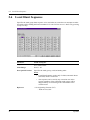
Local Hunt Sequence....................................................................................................76
Trunk to Trunk Restriction .........................................................................................77
System Option...............................................................................................................78
Language Data ..............................................................................................................98
Group............................................................................................. 101
Group...........................................................................................................................102
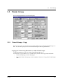
Trunk Group ...............................................................................................................103
Extension Group .........................................................................................................114
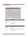
Paging Group ..............................................................................................................124
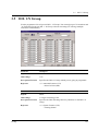
DIL 1:N Group ...........................................................................................................125
OGM Group................................................................................................................128
Line ................................................................................................ 131
Line ..............................................................................................................................132
Trunk Line...................................................................................................................133
Extension Line ............................................................................................................147
DSS Console ................................................................................................................166
Doorphone ...................................................................................................................174
External Paging...........................................................................................................176
ISDN Extension Line..................................................................................................178
Features ......................................................................................... 183
Features .......................................................................................................................184
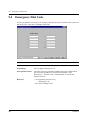
System Speed Dialling ................................................................................................185
Phantom Extension.....................................................................................................187
Emergency Dial Code.................................................................................................188
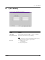
Quick Dialling .............................................................................................................189
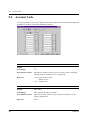
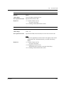
Account Code ..............................................................................................................190
Table of Contents
3
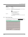
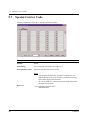
5.7 Special Carrier Code ................................................................................................. 192
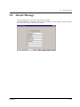
5.8 Absent Message.......................................................................................................... 193
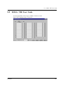
5.9 DISA / TIE User Code............................................................................................... 195
5.10 VPS Integration ....................................................................................................... 197
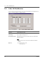
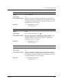
5.11 Caller ID Modification ............................................................................................ 206
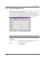
5.12 Caller ID Registration ............................................................................................. 209
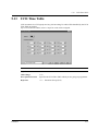
5.13 UCD Time Table ...................................................................................................... 211
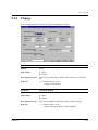
5.14 Charge....................................................................................................................... 213
5.15 Hotel.......................................................................................................................... 216
6
6.1
6.2
6.3
7
7.1
7.2
7.3
7.4
7.5
8
8.1
8.2
9
Toll Restriction.............................................................................. 219
Toll Restriction........................................................................................................... 220
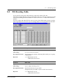
TRS Deny Code.......................................................................................................... 221
TRS Exception Code ................................................................................................. 223
ARS (Automatic Route Selection) ............................................... 225
ARS (Automatic Route Selection) ............................................................................ 226
Time Table .................................................................................................................. 227
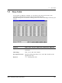
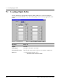
Leading Digits Table.................................................................................................. 228
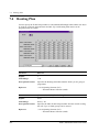
Routing Plan............................................................................................................... 230
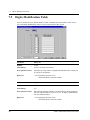
Digits Modification Table .......................................................................................... 232
Private Network ............................................................................ 235
Private Network ......................................................................................................... 236
TIE Routing Table ..................................................................................................... 237
DDI / DID ...................................................................................... 239
9.1
9.2
DDI / DID ................................................................................................................... 240
Number Transformation ........................................................................................... 241
10
Maintenance................................................................................ 247
10.1
10.2
10.3
10.4
10.5
10.6
10.7
Maintenance ............................................................................................................. 248
External Modem 1/2 ................................................................................................ 249
External Modem 2/2 ................................................................................................ 251
SMDR ....................................................................................................................... 252
Power Failure Transfer ........................................................................................... 258
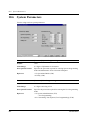
System Parameters .................................................................................................. 260
System Time ............................................................................................................. 265
11
Programming Error Messages .................................................. 269
11.1
11.2
11.3
Error Messages (EXXXX) ...................................................................................... 270
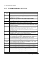
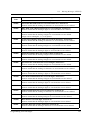
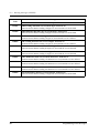
Warning Messages (WXXXX) ................................................................................ 280
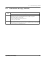
Information Message (IXXXX) .............................................................................. 283
12
Default Values ............................................................................. 285
Index
4
Table of Contents
Section 1
Configuration
Configuration
5
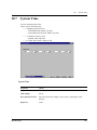
1.1
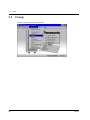
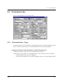
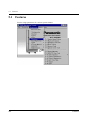
Configuration
1.1
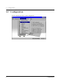
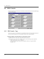
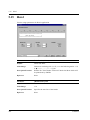
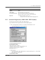
Configuration
Used to determine the basic system configuration.
6
Configuration
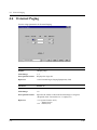
1.2
1.2
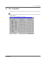
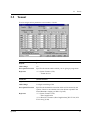
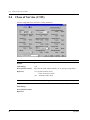
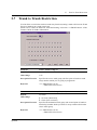
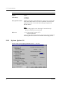
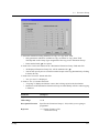
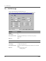
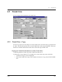
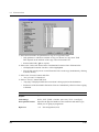
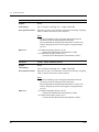
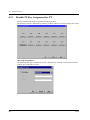
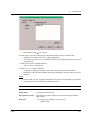
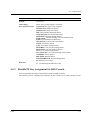
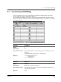
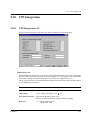
Slot Assignment
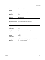
Slot Assignment
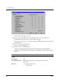
Assigns the type of service cards, inserted in the free slots in the basic and expansion shelves.
Note
In some countries, the E1, the E&M and the ELCOT cards must not be connected to the Public
Switched Network.
The DPH card is not available in some countries.
Configuration
7
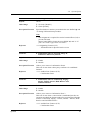
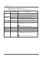
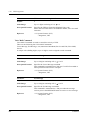
1.2
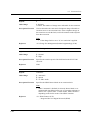
Slot Assignment
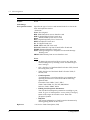
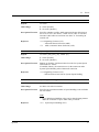
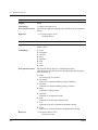
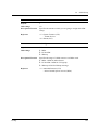
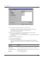
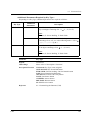
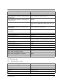
Parameter
Card Type
Default
Blank
Value Range
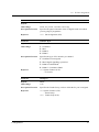
Description/Function
Specifies the type of service card inserted in the free slots in the
basic and expansion shelves.
<Selection>
None: Not assigned.
BRI: ISDN Basic Rate Access Interface card
DHLC: Digital Hybrid Line Circuit card
DISA: Direct Inward System Access card
DLC: Digital Proprietary Line Circuit card
DPH: Doorphone Circuit card
E1: E1 Digital Trunk card
E&M: E&M card (TIE Line card)
ELCOT: Enhanced Loop Start Central Office Trunk card
ERMT: Enhanced Remote Circuit card
ESLC: Enlarged Single Line Telephone Circuit with Message
Waiting card
PRI30: ISDN Primary Rate Access Interface card
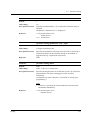
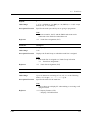
Notes
• To change the current Card Type to a new one, delete the
current setting first by selecting "None" and then assign a
new Card Type.
• CPU - Slot No.13 of the Basic Shelf is fixed to CPU (Central
Processing Unit) card.
• TSW- Slot No.14 of the Basic Shelf is fixed to TSW (TSwitch) card.
• Card Properties
"Card Properties" screen lists and lets you customise the
operating characteristics associated with the following
optional cards.
Extension Cards: DHLC, DLC, ESLC
Trunk Cards: E&M, E1, ELCOT, BRI, PRI30
Resource Cards: ERMT, DISA
• Editing Card Properties Parameters
You can edit Card Properties parameters according to your
needs. To go to "Card Properties" screen, click [Card Type]
button of the target card on this screen. Then click
[Properties] button.
• Help File
You can get information on Card Properties Parameters by
clicking [Help] button on this screen.
Reference
8
• 1.4 Service Cards Description (I/M)
Configuration
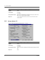
1.2
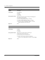
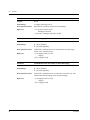
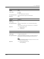
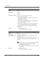
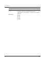
Parameter
Status
Default
—
Value Range
1. INS
2. OUS
3. FAULT
Description/Function
Used to set the status of the service cards.
Slot Assignment
1. INS (In-Service):
The target service card is operating normally.
2. OUS (Out-of-Service):
Programming data for the target service card is entered, but the
target service card is not assigned to the system.
3. FAULT:
The target service card is defective (hardware). In this case, the
LED indicator on the service card is lit.
Reference
Configuration
None
9
1.3
Trunk Port Assignment
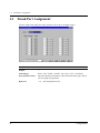
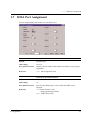
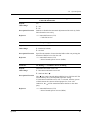
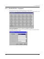
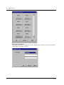
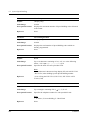
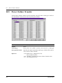
1.3
Trunk Port Assignment
Used to assign each trunk port in the system to one of up to 48 trunk groups.
10
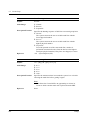
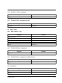
Parameter
Card No.
Default
—
Value Range
XXX : YYY [XXX : Card No. (101-314), YYY : Card Type]
Description/Function
Specifies the physical number of the trunk card and its type, which
you are going to programme.
Reference
• 1.2
Slot Assignment (P/G)
Configuration
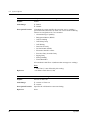
1.3
Trunk Port Assignment
Parameter
Group No.
Default
48: E&M card, 1: Others
Value Range
1 - 48
Description/Function
Specifies the trunk group (1-48) to which the trunk port is assigned.
Notes
• Each trunk port must be assigned to a Trunk Group.
This programme defines the Trunk Group assignment for
each trunk port.
• In some countries, the E1 and the E&M cards must not be
connected to the Public Switched Network.
Reference
• 1.3 System Features (F/G)
– Trunk Group
• 3.2 Trunk Group (P/G)
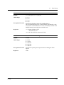
Parameter
Status
Default
—
Value Range
1. INS
2. OUS
3. FAULT
Description/Function
Specifies the operating status of the trunk port.
1. INS: The trunk port is In-Service.
2. OUS: The trunk port is Out-of-Service.
3. FAULT: The trunk port is defective.
Reference
Configuration
None
11
1.4
Extension Port Assignment
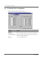
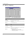
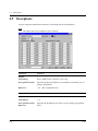
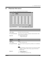
1.4
Extension Port Assignment
Used to set various parameters for extension ports.
XDP extensions are on ports 9 through 16 of a DHLC card.
12
Parameter
Card No.
Default
—
Value Range
XXX : YYY [XXX : Card No. (101-314), YYY : Card Type]
Description/Function
Specifies the physical number of the extension card and its type,
which you are going to programme.
Reference
• 1.2
Slot Assignment (P/G)
Configuration
1.4
Extension Port Assignment
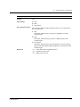
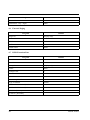
Parameter
Attribute
Default
TEL
Value Range
1. TEL
2. DSS
3. VPS (DPT)
Description/Function
Specifies the attribute of the terminal which is to be connected to
the extension port.
1. TEL
Select this option when you connect a telephone set to the
extension port.
2. DSS
Select this option when you connect a DSS console to the
extension port.
3. VPS (DPT)
Select this option when a port of Panasonic Voice Processing
System (one that supports DPT Integration) is connected to the
extension port.
Reference
Configuration
• 1.5
• 4.3
• 4.4
VPS (DPT) Port Assignment (P/G)
Extension Line (P/G)
DSS Console (P/G)
13
1.4
Extension Port Assignment
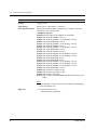
Parameter
Tel. Type
Default
(Display only)
Value Range
Please refer to "Description / Function."
Description/Function
Displays the model number of telephone set which is currently
connected to the extension port.
<Telephone type list>
Unknown: Not connected or Single Line Telephone
T7020: APT with SP-PHONE (12-CO)
T7030: APT with SP-PHONE, 1-Line Display (12-CO)
T7050: APT with MONITOR (12-CO)
T7130: APT with SP-PHONE, 1-Line Display (12-CO)
T7320: APT with SP-PHONE (12-CO)
T7330: APT with SP-PHONE, 1-Line Display (12-CO)
T7350: APT with MONITOR (12-CO)
T7220: DPT with SP-PHONE (24-CO)
T7230: DPT with SP-PHONE, 2-Line Display (24-CO)
T7235: DPT with SP-PHONE, 6-Line Display (12-CO)
T7250: DPT with MONITOR (6-CO)
T7451: DPT with MONITOR (4-CO)
T7531: DPT with SP-PHONE, 1-Line Display (12-CO)
T7533: DPT with SP-PHONE, 3-Line Display (12-CO)
T7536: DPT with SP-PHONE, 6-Line Display (12-CO)
T7550: DPT with MONITOR (12-CO)
T7040: DSS Console (32-DSS, 16-PF)
T7240: DSS Console (32-DSS, 16-PF)
T7540: DSS Console (66-DSS)
T7541: DSS Console with ANSWER and RELEASE buttons (48DSS)
Note
• Some telephones in the above list are not displayed depending
on the destination area.
Reference
14
• 1.3 System Features (F/G)
– Mixed Station Capabilities
Configuration
1.4
Extension Port Assignment
Parameter
DN
Default
1001-: [SP], [NL], [JT], 2001-: [G]
Value Range
3-4 digits consisting of 0-9
Description/Function
Specifies the DN (Directory Number = extension number) for the
extension port.
Note
• You must assign the paired extension for DN after selecting
DSS for the attribute.
Reference
• 2.3
Parameter
Group No.
Default
1
Value Range
1-128
Description/Function
Specifies the Extension Group (1-128) to which the extension port
is assigned.
Numbering Plan (P/G)
Note
• Group No. of the first extension is assigned to #128.
Reference
• 1.3 System Features (F/G)
– Extension Group
• 3.3 Extension Group (P/G)
Parameter
Parallel / XDP
Default
Parallel
Value Range
1. Parallel
2. XDP
Description/Function
Specifies whether to enable or disable "Parallelled Connection of
PT and SLT" or "XDP (eXtra Device Port) Connection of DPT and
SLT."
Reference
• 1.1 System Expansion (F/G)
– EXtra Device Port (XDP)
• 1.3 System Features (F/G)
– Parallelled Telephone
Configuration
15
1.4
Extension Port Assignment
Parameter
Status
Default
—
Value Range
1. INS
2. OUS
3. FAULT
Description/Function
Specifies the operating status of the extension port.
1. INS: The extension port is In-Service
2. OUS: The extension port is Out-of-Service.
3. FAULT: The extension port is defective.
Reference
16
None
Configuration
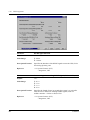
1.5
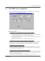
1.5
VPS (DPT) Port Assignment
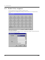
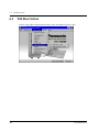
VPS (DPT) Port Assignment
Used to assign parameters for VPS (DPT) ports. Up to eight Panasonic Voice Processing
Systems (VPSs) can be connected to the system.
How to set up a TVP
1. Assignment of the card which will be connected to the VPS System.
• When you use a new DLC / DHLC card and set up the TVP to the PBX:
Assign the card type of the slot to be installed to "DLC" or "DHLC" card and change the
card status to "INS (In-Service)" in "1-1 Slot Assignment" screen.
Then, see the information of "Card Properties" and confirm that the software version of
the card shows more than "1."
• When you connect the TVP to the existing DLC / DHLC : Go to step 2.
2. Assignment of the port which will be connected to the VPS System.
Change the attribute of the port to be connected to the TVP to "VPS (DPT)" in "1-3 Extension
Port Assignment" screen. When the attribute of the port is changed to "VPS (DPT)," the
parameters except "Attribute" will disappear and the directory number will be purged.
3. Assignment of VPS card and its model.
Select the corresponding equipment number in "TVP No." menu, the card (DLC / DHLC)
which connects with the TVP in "VPS Card" menu, and the model of TVP in "Type" menu in
"1-4 VPS (DPT) Port Assignment" screen.
4. Assignment of the extension port connected to the TVP.
Select in "Port No." menu the extension port number of the card (DLC / DHLC) to which the
TVP (DPT) jack is to be connected. This menu is displayed only when the attribute of the port
is assigned to "VPS (DPT)" at step 2.
After "Port No." selection, assign "DN" and "Extension Group No." for the port.
Configuration
17
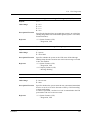
1.5
VPS (DPT) Port Assignment
Save the data changes by clicking "Apply" button.
Then set "Port Status" to "INS (In-Service)."
Jack No.1 must be assigned, because the port is used as the channel to control the VPS.
5. Synchronisation of the communication between the KX-TD500 System and the TVP.
The KX-TD500 System begins synchronisation with the VPS when the step 4 is done.
The "Power" LED of the VPS begins flashing at the same time. The LED will turn on after the
synchronisation is completed. It takes for about 30 seconds to 1 minute to be able to use the
VPS system. It depends on the VPS model and the port number you set up.
18
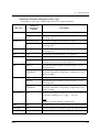
Parameter
TVP No.
Default
1
Value Range
1- 8
Description/Function
Specifies the device number of a Panasonic Voice Processing
System (VPS), which you are going to programme.
Reference
• 1.3 System Features (F/G)
– Integration, VPS
• 1.2 Slot Assignment (P/G)
Parameter
VPS Card
Default
None
Value Range
None, XXX : YYY [XXX : Card No. (101-314), YYY : Card Type]
Description/Function
Specifies the physical number of DLC / DHLC card to which VPS
is connected as extensions.
Reference
• 1.3 System Features (F/G)
– Integration, VPS
• 1.2 Slot Assignment (P/G)
Configuration
1.5
VPS (DPT) Port Assignment
Parameter
Type
Default
None
Value Range
1.
2.
3.
4.
Description/Function
Specifies the model number of the Panasonic Voice Processing
System which will be connected to the VPS card.
None
TVP100
TVP200
TVP200-1
Note
• Please select "TVP200-1," if HDD (Hard Disc) Software
Version of your TVP200 is 2.00 or later.
Reference
• 1.3 System Features (F/G)
– Integration, VPS
Parameter
Jack No.
Default
(Display only)
Value Range
Description/Function
Displays the Jack No. of VPS.
Reference
• 1.3 System Features (F/G)
– Integration, VPS
Parameter
Port No.
Default
Blank
Value Range
1-16 [DLC card]
1-8 [DHLC card]
Description/Function
Specifies the extension port to which the VPS (DPT) jack is to be
connected.
Notes
• This programme tells the system which extension port is
connected to the Panasonic Voice Processing System.
This allows the system to send the proper Digital Integration
information to these ports.
• The port number is displayed only when the attribute of the
port is assigned to VPS (DPT).
Reference
Configuration
• 1.4
Extension Port Assignment (P/G)
19
1.5
VPS (DPT) Port Assignment
Parameter
[Ext No.1] DN
Default
Blank
Value Range
3-4 digits consisting of 0-9
Description/Function
Specifies the extension number for B1 channel.
Note
• This programme allows you to assign an extension number to
each Voice Mail port. Since each port connected to the VPS
provides two extensions, this enables you to assign extension
numbers to each port. To reach the Voice Mail system, users dial
these extension numbers.
Reference
• 2.3
Parameter
[Ext No.1] Group No.
Default
Blank
Value Range
1-128
Description/Function
Specifies the Extension Group (1-128) to which the B1 channel of
the VPS (DPT) port is assigned.
Numbering Plan (P/G)
Note
• Specifies the extension group number to which the type of
extension group, VM or AA, is assigned.
Reference
• 1.3 System Features (F/G)
– Extension Group
• 3.3 Extension Group (P/G)
Parameter
[Ext No.2] DN
Default
Blank
Value Range
3-4 digits consisting of 0-9
Description/Function
Specifies the extension number for B2 channel.
Note
• This programme allows you to assign an extension number to
each Voice Mail port. Since each port connected to the VPS
provides two extensions, this enables you to assign extension
numbers to each port. To reach the Voice Mail system, users dial
these extension numbers.
Reference
20
• 2.3
Numbering Plan (P/G)
Configuration
1.5
VPS (DPT) Port Assignment
Parameter
[Ext No.2] Group No.
Default
Blank
Value Range
1-128
Description/Function
Specifies the Extension Group (1-128) to which the B2 channel of
the VPS (DPT) port is assigned.
Note
• Specifies the extension group number to which the type of
extension group, VM or AA, is assigned.
Reference
• 1.3 System Features (F/G)
– Extension Group
• 3.3 Extension Group (P/G)
Parameter
Status
Default
—
Value Range
1. INS
2. OUS
3. FAULT
Description/Function
Specifies the operating status of the VPS (DPT) port.
1. INS: The VPS port is In-Service.
2. OUS: The VPS port is Out-of-Service.
3. FAULT: The VPS port is defective.
Reference
Configuration
None
21
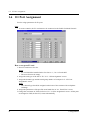
1.6
E1 Port Assignment
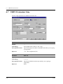
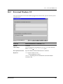
1.6
E1 Port Assignment
Used to assign parameters for E1 ports.
Note
• In some countries, the E1 card must not be connected to the Public Switched Network.
How to set up an E1 card
1. Insert E1 card into a free slot.
Notes
• E1 card should be installed in the free slot no. 1, 5 or 9 of each shelf.
• The next slot must be empty.
2. Assign the card type of the slot to "E1" in "1-1 Slot Assignment" screen.
3. Assign the channel type and the trunk group number of each port in "1-6 E1 Port
Assignment" screen.
Note
• The channel type should be assigned on the basis of the contract with a telephone
exchange.
4. Assign the parameters of the port like usual trunk line in "4-1 Trunk Line" screen.
5. Change the card status to "INS (In-Service)" in "1-1 Slot Assignment" screen. All the ports
are changed to "INS (In-Service)" status automatically.
22
Configuration
1.6
E1 Port Assignment
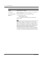
Parameter
Card No.
Default
—
Value Range
XXX : E1 [ XXX : Card No. (101-314)]
Description/Function
Specifies the physical number of the E1 digital trunk card which
you are going to programme.
Reference
• 1.2
Parameter
Channel Type
Default
Undefined
Value Range
1.
2.
3.
4.
Description/Function
Specifies the type of E1 interface per channel.
1.
2.
3.
4.
Slot Assignment (P/G)
Undefined
DR2
E&M-P
E&M-C
Undefined: Not assigned.
DR2: Digital signalling system-R2
E&M-P: Pulsed E&M
E&M-C: Continuous E&M
Reference
• 1.3 System Features (F/G)
– E1 Carrier
Parameter
Group No.
Default
Blank
Value Range
1-48
Description/Function
Specifies the Trunk Group (1-48) to which the E1 port is assigned.
Reference
• 1.3 System Features (F/G)
– Trunk Group
• 3.2 Trunk Group (P/G)
Configuration
23
1.6
E1 Port Assignment
Parameter
Receiver Type
Default
Undefined
Value Range
1.
2.
3.
4.
Description/Function
Specifies the dial type when receiving an incoming call.
1.
2.
3.
4.
Undefined
Pulse
DTMF
MFC-R2
Undefined: Not assigned.
Pulse: DP Signalling sending / receiving
DTMF: DTMF Signalling sending / receiving
MFC-R2: MFC-R2 Signalling sending / receiving
(Digital signalling system-R2 only)
Reference
None
Parameter
Status
Default
—
Value Range
1. INS
2. OUS
3. FAULT
Description/Function
Specifies the operating status of the E1 port.
1. INS: The E1 port is In-Service.
2. OUS: The E1 port is Out-of-Service.
3. FAULT: The E1 port is defective (hardware).
In this case, the LED indicator on the E1 card will light.
Reference
24
None
Configuration
1.7
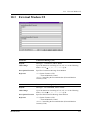
1.7
DISA Port Assignment
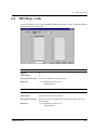
DISA Port Assignment
Used to assign OGM group number for each DISA card.
Parameter
[Card No.1-8] Location
Default
(Display only)
Value Range
101-314
Description/Function
Displays the slot number of the DISA card which you are going to
programme.
Reference
• 1.2
Parameter
[Card No.1-8] OGM Group No.
Default
1
Value Range
1-8
Description/Function
Specifies the OGM Group (1-8) to which the DISA card is
assigned.
Reference
• 1.3 System Features (F/G)
– Outgoing Message (OGM)
• 3.6 OGM Group (P/G)
Configuration
Slot Assignment (P/G)
25
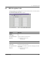
1.8
BRI Port Assignment
1.8
BRI Port Assignment
Used to assign the parameters for BRI (Basic Rate Interface) ports.
26
Parameter
Card No.
Default
—
Value Range
XXX: BRI [XXX: Card No. (101-314)]
Description/Function
Specifies the physical number of the BRI card which you are going
to programme.
Reference
• 1.2
Parameter
Type
Default
CO
Value Range
1. CO
2. EXT
Description/Function
Specifies the type of each BRI port either "CO" (CO line) or "EXT"
(extension line) on a BRI port basis.
Reference
• 2.1 ISDN Features (F/G)
– Integrated Services Digital Network (ISDN)
– Integrated Services Digital Network (ISDN) Extension
• 4.7 ISDN Extension Line (P/G)
Slot Assignment (P/G)
Configuration
1.8
BRI Port Assignment
Parameter
DN
Default
Blank
Value Range
3-4 digits consisting of 0-9 or X
Description/Function
Specifies the DN (Directory Number) for the BRI port.
(Assignable only when "EXT" is specified in "Type" assignment.)
Note
• "X" can be used as a wild card character which substitutes any
digit in its position. The last one or two digits of DN may be
"X."
Reference
• 2.3
Parameter
Group No.
Default
1
Value Range
1-48 or 1-128
Description/Function
Type: CO
Specifies the Trunk Group (1-48) to which the BRI port is assigned.
Type: EXT
Specifies the Extension Group (1-128) to which the BRI port is
assigned.
Reference
• 1.3 System Features (F/G)
– Extension Group
– Trunk Group
• 3.2 Trunk Group (P/G)
• 3.3 Extension Group (P/G)
Parameter
Status
Default
—
Value Range
1. INS
2. OUS
3. FAULT
Description/Function
Specifies the operating status of the BRI port.
Numbering Plan (P/G)
1. INS: The BRI port is In-Service.
2. OUS: The BRI port is Out-of-Service.
3. FAULT: The BRI port is defective (hardware).
In this case, the LED indicator on the BRI card will light.
Reference
Configuration
None
27
1.9
PRI Port Assignment
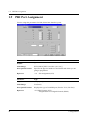
1.9
PRI Port Assignment
Used to assign the parameters for PRI (Prime Rate Interface) ports.
28
Parameter
Card No.
Default
—
Value Range
XXX: PRI30 [XXX: Card No. (101–314)]
Description/Function
Specifies the physical number of the PRI30 card which you are
going to programme.
Reference
• 1.2
Parameter
Type
Default
(Display only)
Value Range
CO (fixed)
Description/Function
Displays the type of each PRI port (fixed to "CO" (CO line)).
Reference
• 2.1 ISDN Features (F/G)
– Integrated Services Digital Network (ISDN)
Slot Assignment (P/G)
Configuration
1.9
PRI Port Assignment
Parameter
Group No.
Default
1
Value Range
1-48
Description/Function
Specifies the Trunk Group (1-48) to which the PRI port is assigned.
Reference
• 1.3 System Features (F/G)
– Trunk Group
• 3.2 Trunk Group (P/G)
Parameter
Status
Default
—
Value Range
1. INS
2. OUS
3. FAULT
Description/Function
Specifies the operating status of each PRI port.
1. INS: The PRI port is In-Service.
2. OUS: The PRI port is Out-of-Service.
3. FAULT: The PRI port is defective (hardware).
In this case, the LED indicator on the PRI30 card will light.
Reference
Configuration
None
29
1.9
30
PRI Port Assignment
Configuration
Section 2
System
System
31
2.1
System
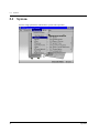
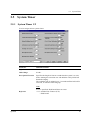
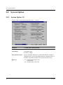
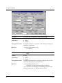
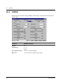
2.1
System
Used to assign parameters which affect system-wide operation.
32
System
2.2
2.2
Tenant
Tenant
Used to assign various parameters on a tenant (1-8) basis.
System
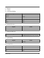
Parameter
Tenant No.
Default
1
Value Range
1-8
Description/Function
Specifies the tenant number which you are going to programme.
Reference
• 1.3 System Features (F/G)
– Tenant Service
Parameter
Alert Extension
Default
Blank
Value Range
3-4 digits consisting of 0-9
Description/Function
Specifies the destination extension which will be alerted by the
system, if there is an extension user who did not respond to the
Timed Reminder ringing (or Wake-Up Call).
Reference
• 1.3 System Features (F/G)
– Hotel Application
• 3.2.6 Hotel Use Features (Hotel Application) [KX-T7536, KXT7235 only] (U/M)
33
2.2
Tenant
Parameter
DAY / NIGHT Switching Mode
Default
Manual
Value Range
1. Manual
2. Auto
Description/Function
Specifies the Day / Night switching mode, Manual or Auto.
1. Manual
The extension allowed by COS (Class of Service)
programming, the Manager or the Operators can switch Day /
Night mode at any time desired by dialling the feature number
for "Night Mode set / cancel."
2. Auto
The system automatically switches the Day / Night mode each
day at the time programmed in Auto Start Time.
Reference
• 2.11.4 Switching the Day / Night Service (U/M)
Parameter
Inter-tenant Calling (1 - 8)
Default
No check
Value Range
1. No check [Disallowed]
2. Check [Allowed]
Description/Function
Specifies other tenant numbers to which extensions in this tenant
can make a call.
If no tenant numbers are checked in this field, extension users
within this tenant cannot make a call to extensions in other tenants.
Making calls from one tenant to another is not allowed by default.
Reference
• 1.3 System Features (F/G)
– Tenant Service
(Auto Start Time)
Specifies "Start" time of DAY / NIGHT service on a day of the week basis.
(This setting is valid when "Auto mode" is selected in "DAY / NIGHT Switching Mode"
setting.)
Up to four time frames (Day 1, Night 1, Day 2, Night 2) can be set up on each day of the week.
34
System
2.2
System
Parameter
Day 1 (SUN-SAT)
Default
9:00 AM
Value Range
1. Disable
2. 12:00-11:59 PM / AM
Description/Function
Specifies the start time for Day Service 1.
Reference
• 1.3 System Features (F/G)
– Night Service
Parameter
Night 1 (SUN-SAT)
Default
5:00 PM
Value Range
Same as Day 1
Description/Function
Specifies the start time for Night Service 1.
Reference
• 1.3 System Features (F/G)
– Night Service
Parameter
Day 2 (SUN-SAT)
Default
Disable
Value Range
Same as Day 1
Description/Function
Specifies the start time for Day Service 2.
Reference
• 1.3 System Features (F/G)
– Night Service
Parameter
Night 2 (SUN-SAT)
Default
Disable
Value Range
Same as Day 1
Description/Function
Specifies the start time for Night Service 2.
Reference
• 1.3 System Features (F/G)
– Night Service
Tenant
35
2.2
Tenant
Parameter
Music on Hold Source
Default
MUS1: [SP], [NL], [G], Tone: [JT]
Value Range
1.
2.
3.
4.
Description/Function
Specifies the Music Source port to be used for Music on Hold.
None
MUS1
MUS2
Tone
Note
• If "MUS2" is selected, the actual source depends upon the
position of the switch located on the TSW card. "MUS2 (Music
2 jack)" or "INT MUS (internal music)" can be selected by this
switch.
Reference
• 1.3 System Features (F/G)
– Music on Hold
• 2.3.2 TSW Card (I/M)
Parameter
BGM Source
Default
MUS1
Value Range
1. None
2. MUS1
3. MUS2
Description/Function
Specifies the Music Source port to be used for BGM.
Note
• If "MUS2" is selected, the actual source depends upon the
position of the switch located on the TSW card. "MUS2 (Music
2 jack)" or "INT MUS (internal music)" can be selected by this
switch.
Reference
36
• 2.8.3 Music Source (External/Internal) (I/M)
System
2.2
Tenant
Parameter
Automatic Route Selection
Default
No check
Value Range
1. Check [Enable]
2. No check [Disable]
Description/Function
Specifies whether to utilise ARS (Automatic Route Selection) or
not. If set to "No" (No check), "Trunk Access, Idle" is activated
instead of ARS when an extension user dials "9" for making an
outside call.
Reference
• 1.6 Originating Features (F/G)
– Automatic Route Selection (ARS)
• 7.1 ARS (Automatic Route Selection) (P/G)
Parameter
System Speed Dial TRS Level Override
Default
No check: [SP], [NL], [JT], Check: [G]
Value Range
1. Check [Enable]
2. No check [Disable]
Description/Function
Enables or disables "Toll Restriction Override for System Speed
Dial Numbers" feature.
If enabled (Check), all extension users in the tenant can make
System Speed Dialling calls without toll restriction.
Reference
• 1.6 Originating Features (F/G)
–Toll Restriction Override for System Speed Dialling
Parameter
System Speed Dialing Entries Max.
Default
Tenant 1:1000, Tenant 2:1000, Tenant 3-8:0
Value Range
0-1000 in 20 codes increments
Description/Function
Specifies the maximum number of Speed Dialling codes available
for each tenant.
Note
• Up to 2000 Speed Dialling codes can be shared among tenants
under the restriction of up to 1000 codes per tenant.
Reference
System
• 5.2
System Speed Dialling (P/G)
37
2.2
38
Tenant
Parameter
Manager Extension DN
Default
Blank
Value Range
3-4 digits consisting of 0-9
Description/Function
Specifies the extension number for the Manager.
Reference
• 1.3 System Features (F/G)
–Manager Extension
• 3 Operator / Manager Operation (U/M)
Parameter
External Paging Tone
Default
Check
Value Range
1. Check [Enable]
2. No check [Disable]
Description/Function
If checked, confirmation tone is emitted from external pagers
before voice announcement.
Reference
• 1.14 Paging Features (F/G)
– Paging
• 2.6.1 Paging (U/M)
Parameter
Confirmation Tone for Station or External Paging
Default
Check
Value Range
1. Check [Enable]
2. No check [Disable]
Description/Function
If checked, confirmation tone is sent to the extension user who
initiated the Station Paging or the External Paging.
Reference
• 1.14 Paging Features (F/G)
– Paging
• 2.6.1 Paging (U/M)
System
2.3
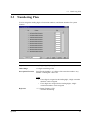
2.3
Numbering Plan
Numbering Plan
Used to assign the leading digits of extension numbers, and feature numbers for system
features.
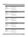
Parameter
1 1st Hundred Block Extension
Default
10: [SP], [NL], [JT], 20: [G]
Value Range
1-2 digits consisting of 0-9
Description/Function
Specifies the leading 1 or 2 digits of the extension number. Any
number "0 through 9" can be set.
Notes
• If one digit is assigned as the leading digit, 3-digit extension
numbers can be assigned.
• If two digits are assigned as the leading digits, 4-digit
extension numbers can be assigned.
Reference
System
• 1.3 System Features (F/G)
– Flexible Numbering
39
2.3
40
Numbering Plan
Parameter
2 2nd Hundred Block Extension
Default
11: [SP], [NL], [JT], 21: [G]
Value Range
1-2 digits consisting of 0-9
Description/Function
Same as the Parameter 1.
Reference
• 1.3 System Features (F/G)
– Flexible Numbering
Parameter
3 3rd Hundred Block Extension
Default
12: [SP], [NL], [JT], 22: [G]
Value Range
1-2 digits consisting of 0-9
Description/Function
Same as the Parameter 1.
Reference
• 1.3 System Features (F/G)
– Flexible Numbering
Parameter
4 4th Hundred Block Extension
Default
13: [SP], [NL], [JT], 23: [G]
Value Range
1-2 digits consisting of 0-9
Description/Function
Same as the Parameter 1.
Reference
• 1.3 System Features (F/G)
– Flexible Numbering
Parameter
5 5th Hundred Block Extension
Default
14: [SP], [NL], [JT], 24: [G]
Value Range
1-2 digits consisting of 0-9
Description/Function
Same as the Parameter 1.
Reference
• 1.3 System Features (F/G)
– Flexible Numbering
Parameter
6 6th Hundred Block Extension
Default
20: [SP], [NL], [JT], 30: [G]
Value Range
1-2 digits consisting of 0-9
Description/Function
Same as the Parameter 1.
Reference
• 1.3 System Features (F/G)
– Flexible Numbering
System
2.3
System
Parameter
7 7th Hundred Block Extension
Default
21: [SP], [NL], [JT], 31: [G]
Value Range
1-2 digits consisting of 0-9
Description/Function
Same as the Parameter 1.
Reference
• 1.3 System Features (F/G)
– Flexible Numbering
Parameter
8 8th Hundred Block Extension
Default
22: [SP], [NL], [JT], 32: [G]
Value Range
1-2 digits consisting of 0-9
Description/Function
Same as the Parameter 1.
Reference
• 1.3 System Features (F/G)
– Flexible Numbering
Parameter
9 9th Hundred Block Extension
Default
23: [SP], [NL], [JT], 33: [G]
Value Range
1-2 digits consisting of 0-9
Description/Function
Same as the Parameter 1.
Reference
• 1.3 System Features (F/G)
– Flexible Numbering
Parameter
10 10th Hundred Block Extension
Default
24: [SP], [NL], [JT], 34: [G]
Value Range
1-2 digits consisting of 0-9
Description/Function
Same as the Parameter 1.
Reference
• 1.3 System Features (F/G)
–Flexible Numbering
Numbering Plan
41
2.3
42
Numbering Plan
Parameter
11-16 11th Hundred Block Extension - 16th
Hundred Block Extension
Default
Blank
Value Range
1-2 digits consisting of 0-9
Description/Function
Same as the Parameter 1.
Reference
• 1.3 System Features (F/G)
–Flexible Numbering
Parameter
17 Operator Call
Default
0: [SP], 9: [NL], [JT], [G]
Value Range
1-4 digits consisting of 0-9,
Description/Function
Specifies the feature number for calling the Operator.
FDN for each Operator Group can also be used for this purpose.
Reference
• 2.2.1 Basic Calling (U/M)
Parameter
18 Local CO Line Access / ARS
Default
9: [SP], 0: [NL], [JT], [G]
Value Range
1-4 digits consisting of 0-9,
Description/Function
Specifies the feature number for making an outside call by "ARS
(Automatic Route Selection)" or "Trunk Access, Idle."
Reference
• 2.2.1 Basic Calling (U/M)
Parameter
19 Trunk Group Access
Default
8
Value Range
1-4 digits consisting of 0-9,
Description/Function
Specifies the feature number for making an outside call by
specifying a Trunk Group (01-48).
Reference
• 2.2.1 Basic Calling (U/M)
or #
or #
or #
System
2.3
System
Numbering Plan
Parameter
20 Speed Dialing - System
Default
*
Value Range
1-4 digits consisting of 0-9,
Description/Function
Specifies the feature number for making a call using a System
Speed Dialling number.
Reference
• 2.2.2 Easy Dialling (U/M)
Parameter
21 Speed Dialing - Station
Default
3*: [SP], [NL], [JT], 6*: [G]
Value Range
1-4 digits consisting of 0-9,
Description/Function
Specifies the feature number for making a call using a Station
Speed Dialling number.
Reference
• 2.2.2 Easy Dialling (U/M)
Parameter
22 Speed Dialing - Station Programming
Default
30: [SP], [NL], [JT], 60: [G]
Value Range
1-4 digits consisting of 0-9,
Description/Function
Specifies the feature number for programming Station Speed
Dialling numbers at each extension.
Reference
• 2.2.2 Easy Dialling (U/M)
Parameter
23 Doorphone Call
Default
31: [SP], [NL], [JT], 68: [G]
Value Range
1-4 digits consisting of 0-9,
Description/Function
Specifies the feature number for making a call to a doorphone.
Reference
• 2.8.1 If a Doorphone / Door Opener is Connected (U/M)
Parameter
24 External Paging
Default
32: [SP], [NL], [JT], 64: [G]
Value Range
1-4 digits consisting of 0-9,
Description/Function
Specifies the feature number for making a paging announcement
through External Pagers.
Reference
• 2.6.1 Paging (U/M)
or #
or #
or #
or #
or #
43
2.3
44
Numbering Plan
Parameter
25 External Paging Answer / TAFAS Answer
Default
42: [SP], [NL], [JT], 44: [G]
Value Range
1-4 digits consisting of 0-9,
Description/Function
Specifies the feature number for answering paging announcements
through External Pagers or TAFAS (Trunk Answer From Any
Station) calls.
Reference
• 2.6.3 Answering a Paged Announcement (U/M)
Parameter
26 Station Paging
Default
33: [SP], [NL], [JT], 63: [G]
Value Range
1-4 digits consisting of 0-9,
Description/Function
Specifies the feature number for making a paging announcement
through the built-in speakers of PTs.
Reference
• 2.6.1 Paging (U/M)
Parameter
27 Station Paging Answer
Default
43
Value Range
1-4 digits consisting of 0-9,
Description/Function
Specifies the feature number for answering the paging
announcement through the built-in speakers of PTs.
Reference
• 2.6.3 Answering a Paged Announcement (U/M)
Parameter
28 CO Call Pickup
Default
4*
Value Range
1-4 digits consisting of 0-9,
Description/Function
Specifies the feature number for answering a CO call ringing at
another extension.
Reference
• 2.3.3 Answering a Call Ringing at Another Telephone (Call
Pickup) (U/M)
or #
or #
or #
or #
System
2.3
System
Numbering Plan
Parameter
29 Group Call Pickup
Default
40
Value Range
1-4 digits consisting of 0-9,
Description/Function
Specifies the feature number for answering a call ringing at another
extension in the same Extension Group.
Reference
• 2.3.3 Answering a Call Ringing at Another Telephone (Call
Pickup) (U/M)
Parameter
30 Directed Call Pickup
Default
41
Value Range
1-4 digits consisting of 0-9,
Description/Function
Specifies the feature number for answering a call ringing at another
extension.
Reference
• 2.3.3 Answering a Call Ringing at Another Telephone (Call
Pickup) (U/M)
Parameter
31 Hold
Default
50
Value Range
1-4 digits consisting of 0-9,
Description/Function
Specifies the feature number for putting a call on hold.
Reference
• 2.4.1 Holding a Call (U/M)
Parameter
32 Hold Retrieve - Station
Default
51
Value Range
1-4 digits consisting of 0-9,
Description/Function
Specifies the feature number for retrieving a call held at another
extension.
Reference
• 2.4.1 Holding a Call (U/M)
or #
or #
or #
or #
45
2.3
46
Numbering Plan
Parameter
33 Hold Retrieve - Trunk
Default
53
Value Range
1-4 digits consisting of 0-9,
Description/Function
Specifies the feature number for retrieving a specific outside call
held at another extension.
Reference
• 2.4.1 Holding a Call (U/M)
Parameter
34 Redial
Default
#
Value Range
1-4 digits consisting of 0-9,
Description/Function
Specifies the feature number for dialling the last number dialled.
Reference
• 2.2.3 Redial (U/M)
Parameter
35 Call Park / Call Park Retrieve
Default
52
Value Range
1-4 digits consisting of 0-9,
Description/Function
Specifies the feature number for placing a call on hold / retrieving
the call held in the system-common parking area.
Reference
• 2.4.1 Holding a Call (U/M)
Parameter
36 Account Code
Default
49
Value Range
1-4 digits consisting of 0-9,
Description/Function
Specifies the feature number for entering account codes which may
be forced or optional depending on Class of Service programming.
Reference
• 2.2.5 Calling without Restrictions (U/M)
Parameter
37 Door Open
Default
55
Value Range
1-4 digits consisting of 0-9,
Description/Function
Specifies the feature number for unlocking the Door Opener.
Reference
• 2.8.1 If a Doorphone / Door Opener is Connected (U/M)
or #
or #
or #
or #
or #
System
2.3
System
Numbering Plan
Parameter
38 External Feature Access
Default
6: [SP], [NL], [JT], 66: [G]
Value Range
1-4 digits consisting of 0-9,
Description/Function
Specifies the feature number for sending a switchhook flash to a
host PBX or Centrex system. This is useful when the host PBX
offers, for example, "Call Waiting" call.
Reference
• 2.8.2 If a Host PBX is Connected (U/M)
Parameter
39 Station Program Clear
Default
790
Value Range
1-4 digits consisting of 0-9,
Description/Function
Specifies the feature number for Station Programme Clear.
Reference
• 2.7.14 Clearing the Feature Settings at Your Extension (Station
Programme Clear) (U/M)
Parameter
40 Message Waiting Set / Cancel / Call Back
Default
70
Value Range
1-4 digits consisting of 0-9,
Description/Function
Specifies the feature number for setting / cancelling the Message
Waiting indications.
This is also used to call back the party who left a Message Waiting
indication.
Reference
• 2.2.4 When the Dialled Line is Busy or There is No Answer (U/
M)
Parameter
41 OGM Playback / Record
Default
36: [SP], [NL], [JT], 712: [G]
Value Range
1-4 digits consisting of 0-9,
Description/Function
Specifies the feature number for recording / playing back an OGM
(Outgoing Message) [For Manager, Operator only].
Reference
• 3.2.2 Recording Outgoing Messages (U/M)
or #
or #
or #
or #
47
2.3
48
Numbering Plan
Parameter
42 Call FWD - Do Not Disturb Set / Cancel
Default
710
Value Range
1-4 digits consisting of 0-9,
Description/Function
Specifies the feature number for setting / cancelling the Call
Forwarding / Do Not Disturb feature.
Reference
• 2.5.1 Forwarding Your Calls (Call Forwarding) (U/M)
• 2.7.2 Refusing Incoming Calls (Do Not Disturb [DND]) (U/M)
Parameter
43 Dial Call Pickup Deny Set / Cancel
Default
720
Value Range
1-4 digits consisting of 0-9,
Description/Function
Specifies the feature number for setting / cancelling the Dial Call
Pickup deny feature.
Reference
• 2.7.8 Denying Other People the Possibility of Picking up Your
Calls (Call Pickup Deny) (U/M)
Parameter
44 Data Line Security Set / Cancel
Default
730
Value Range
1-4 digits consisting of 0-9,
Description/Function
Specifies the feature number for setting / cancelling the Data Line
Security feature.
Reference
• 2.7.11 Protecting Your Line against Indication Tones (Data Line
Security) (U/M)
Parameter
45 Call Waiting Set / Cancel
Default
731
Value Range
1-4 digits consisting of 0-9,
Description/Function
Specifies the feature number for setting / cancelling Call Waiting
feature.
Reference
• 2.7.3 Receiving a Call Waiting (Call Waiting / Off-Hook Call
Announcement [OHCA] / Whisper OHCA) (U/M)
or #
or #
or #
or #
System
2.3
System
Numbering Plan
Parameter
46 Executive Busy Override Deny Set / Cancel
Default
733
Value Range
1-4 digits consisting of 0-9,
Description/Function
Specifies the feature number for setting / cancelling Executive
Busy Override Deny feature.
Reference
• 2.7.9 Denying Other People the Possibility of Joining Your
Conversation (Executive Busy Override Deny) (U/M)
Parameter
47 Pickup Dialing Program / Set / Cancel
Default
74
Value Range
1-4 digits consisting of 0-9,
Description/Function
Specifies the feature number for programming / setting / cancelling
Pickup Dialling feature.
Reference
• 2.2.2 Easy Dialling (U/M)
Parameter
48 Absent Message Set / Cancel
Default
750
Value Range
1-4 digits consisting of 0-9,
Description/Function
Specifies the feature number for setting / cancelling Absent
Message feature.
Reference
• 2.5.3 Showing an Absent Message on the Caller's Telephone
Display (Absent Message Capability) (U/M)
Parameter
49 Timed Reminder Confirm / Set / Cancel
Default
761: [SP], [NL], [JT], 76: [G]
Value Range
1-4 digits consisting of 0-9,
Description/Function
Specifies the feature number for confirming / setting / cancelling
Timed Reminder feature.
Reference
• 2.7.1 Setting the Alarm (Timed Reminder (Wake-Up Call)) (U/M)
or #
or #
or #
or #
49
2.3
50
Numbering Plan
Parameter
50 Station Lock Set / Cancel
Default
762: [SP], [NL], [JT], 77: [G]
Value Range
1-4 digits consisting of 0-9,
Description/Function
Specifies the feature number for setting / cancelling Electronic
Station Lockout feature.
Reference
• 2.5.4 Preventing Other People from Using Your Telephone
(Electronic Station Lockout) (U/M)
Parameter
51 Night Mode Set / Cancel
Default
78
Value Range
1-4 digits consisting of 0-9,
Description/Function
Specifies the feature number for turning on / off the Night Service
mode.
Reference
• 2.11.4 Switching the Day / Night Service (U/M)
Parameter
52 Parallel Telephone Mode
Default
39
Value Range
1-4 digits consisting of 0-9,
Description/Function
Specifies the feature number for setting / cancelling Parallel
Telephone mode.
Reference
• 2.7.13 Setting the Parallel Connected Telephone Ringer
(Parallelled Telephone Connection) (U/M)
Parameter
53 External BGM On / Off
Default
35
Value Range
1-4 digits consisting of 0-9,
Description/Function
Specifies the feature number for turning on / off External BGM
[For Manager, Operator only].
Reference
• 3.2.1 Turning on the External Background Music (Background
Music [BGM] - External) (U/M)
or #
or #
or #
or #
System
2.3
System
Numbering Plan
Parameter
54 Live Call Screening
Default
799
Value Range
1-4 digits consisting of 0-9,
Description/Function
Specifies the feature number for setting / cancelling Live Call
Screening feature.
Reference
• 2.8.3 If a Voice Processing System is Connected (U/M)
Parameter
55 Call Log Incoming, Overwrite Mode
Default
56: [SP], [NL], [JT], 54: [G]
Value Range
1-4 digits consisting of 0-9,
Description/Function
Specifies the feature number for turning on / off the Call Log
Incoming, Overwrite Mode. If turned on (e.g., 561), overwriting the
buffer will occur. If turned off (e.g., 560), new data will be
disregarded when the buffer is full.
Reference
• 2.10.1 Calling Using the Call Log (Incoming Call Log) [KXT7533, KX-T7536, KX-T7230, KX-T7235 only] (U/M)
Parameter
56 Call Log Incoming, Log Lock
Default
57: [SP], [NL], [JT], 59: [G]
Value Range
1-4 digits consisting of 0-9,
Description/Function
Specifies the feature number for turning on / off the Call Log
Incoming, Log Lock. A 3-digit password is needed. Use it twice
(e.g., 57123123) to turn on the lock, and use it once (i.e., 57123) to
turn off the lock. [For Manager, Operator only]
Reference
• 2.10.3 Denying Other People the Possibility of Seeing Your Call
Log (Incoming Call Log Lock) [KX-T7533, KX-T7536, KXT7230, KX-T7235 only] (U/M)
Parameter
57 Timed Reminder, Remote
Default
7*
Value Range
1-4 digits consisting of 0-9,
Description/Function
Specifies the feature number for setting / cancelling Timed
Reminder, Remote feature [For Manager, Operator only].
Reference
• 3.1.1 Setting the Alarm for Other Extensions (Remote Timed
Reminder (Wake-Up Call)) (U/M)
or #
or #
or #
or #
51
2.3
52
Numbering Plan
Parameter
58 Login / Logout
Default
45
Value Range
1-4 digits consisting of 0-9,
Description/Function
Specifies the feature number for Log-in / Log-out.
Reference
• 2.5.5 Leaving an Extension Group (Log-In / Log-Out) (U/M)
Parameter
59 Automatic Callback Busy Cancel
Default
46
Value Range
1-4 digits consisting of 0-9,
Description/Function
Specifies the feature number for cancelling Automatic Callback
Busy feature.
Reference
• 2.2.4 When the Dialled Line is Busy or There is No Answer (U/
M)
Parameter
60 Walking COS
Default
47
Value Range
1-4 digits consisting of 0-9,
Description/Function
Specifies the feature number for setting / cancelling Walking COS
feature.
Reference
• 2.2.5 Calling without Restrictions (U/M)
Parameter
61 MODEM Control
Default
791: [SP], [NL], [JT], Blank: [G]
Value Range
1-4 digits consisting of 0-9,
Description/Function
Specifies the feature number for External Modem Control. An
external modem can be connected to RS-232C port 1.
Reference
• 2.11.1 Controlling the External Modem (External Modem
Control) (U/M)
or #
or #
or #
or #
System
2.3
Numbering Plan
Parameter
62 MCID
Default
737
Value Range
1-4 digits consisting of 0-9,
Description/Function
Specifies the feature number for turning on / off the MCID
(Malicious Call Identification) feature.
Reference
• 2.7.15 Identifying Malicious Callers (Malicious Call
Identification [MCID]) (U/M)
Parameter
63-70 Quick dial 1 - Quick dial 8
Default
Blank
Value Range
1-4 digits consisting of 0-9,
Description/Function
Specifies the feature number for Quick Dial features.
Reference
• 2.2.2 Easy Dialling (U/M)
Parameter
71 Reserved (Reserved for future use.)
Default
Blank
or #
or #
Value Range
Description/Function
Reference
System
Parameter
72 Remote DND
Default
722
Value Range
1-4 digits consisting of 0-9,
Description/Function
Specifies the feature number for setting / cancelling the DND (Do
Not Disturb) feature for other extensions [For Manager, Operator
only].
Reference
• 3.1.2 Setting or Cancelling the DND Feature to Other Extensions
(Remote DND Control) (U/M)
or #
53
2.3
54
Numbering Plan
Parameter
73 Remote FWD Cancel-Once
Default
723
Value Range
1-4 digits consisting of 0-9,
Description/Function
With this feature number, the Manager or the Operators can reach
an extension that has set Call Forwarding. It is one time ("once")
cancellation, not a permanent cancellation of Call Forwarding on
the destination.
[For Manager, Operator only].
Reference
• 3.1.3 Calling the Extension that has set Call Forwarding (Remote
FWD Cancel-Once) (U/M)
Parameter
74 Trunk Route Control
Default
724
Value Range
1-4 digits consisting of 0-9,
Description/Function
Specifies the feature number for Trunk Route Control
[For Manager, Operator only].
Reference
• 3.2.4 Trunk Route Control (U/M)
Parameter
75 UCD Monitor Mode
Default
725
Value Range
1-4 digits consisting of 0-9,
Description/Function
Specifies the feature number for UCD Monitor mode. One
supervisor can be assigned per UCD Group. The supervisor can
monitor the number of calls in the waiting queue.
Reference
• 2.11.3 Monitoring the Number of UCD Calls Waiting to be
Answered (UCD Monitor Mode) (U/M)
Parameter
76 TIE Line Access
Default
77: [SP], [NL], [JT], Blank: [G]
Value Range
1-4 digits consisting of 0-9,
Description/Function
Specifies the feature number for making a TIE line call.
Reference
• 3.1 E&M Features (F/G)
– E&M (TIE) Line Service
or #
or #
or #
or #
System
2.3
System
Numbering Plan
Parameter
77-92 Other PBX 01 - Other PBX 16
Default
Blank
Value Range
1-2 digits consisting of 0-9
Description/Function
Specifies the leading 1 or 2 digits of the other PBX extension
numbers.
If you employ PBX code method for TIE calls, this programming
is not required.
Reference
• 3.1 E&M Features (F/G)
–E&M (TIE) Line Service
Parameter
93 Paging Deny Set / Cancel
Default
721
Value Range
1-4 digits consisting of 0-9,
Description/Function
Specifies the feature number for setting / cancelling Paging Deny
feature.
Reference
• 2.7.4 Denying the Paged Announcement (Paging – Deny) (U/M)
Parameter
94 Trunk Busy-out
Default
726
Value Range
1-4 digits consisting of 0-9,
Description/Function
Specifies the feature number for Trunk Busy-out feature [For
Manager, Operator only].
Reference
• 3.2.3 Trunk Busy-out Setting (U/M)
Parameter
95 Walking Station
Default
727
Value Range
1-4 digits consisting of 0-9,
Description/Function
Specifies the feature number for Walking Station feature.
Reference
• 2.9.1 Using the Same Extension Number and the Setting of Your
Previous Extension (Walking Station) (U/M)
or #
or #
or #
55
2.3
56
Numbering Plan
Parameter
96 CLIP / COLP
Default
711
Value Range
1-4 digits consisting of 0-9,
Description/Function
Specifies the feature number for turning on / off the CLIP / COLP
(Calling / Connected Line Indentification Presentation) feature.
Reference
• 2.7.5 Displaying Your Number on the Called Party and Calling
Party's Telephone (Calling / Connected Line Identification
Presentation [CLIP / COLP]) (U/M)
Parameter
97 CLIR
Default
59: [SP], [NL], [JT], 57: [G]
Value Range
1-4 digits consisting of 0-9,
Description/Function
Specifies the feature number for turning on / off the CLIR (Calling
Line Identification Restriction) feature.
Reference
• 2.7.6 Preventing Your Number Being Displayed on the Called
Party's Telephone (Calling Line Identification Restriction [CLIR])
(U/M)
Parameter
98 COLR
Default
58
Value Range
1-4 digits consisting of 0-9,
Description/Function
Specifies the feature number for turning on / off the COLR
(Connected Line Identification Restriction) feature.
Reference
• 2.7.7 Preventing Your Number Being Displayed on the Called
Party's Telephone (Connected Line Identification Restriction
[COLR]) (U/M)
Parameter
99 Dial Information (CTI)
Default
Blank
Value Range
1-4 digits consisting of 0-9,
Description/Function
Specifies the feature number for turning on / off the CTI (Computer
Telephony Integration) Dial Information feature.
Reference
None
or #
or #
or #
or #
System
2.3
Numbering Plan
Parameter
100 COS Primary
Default
792: [SP], [NL], [JT], 79: [G]
Value Range
1-4 digits consisting of 0-9,
Description/Function
Specifies the feature number for setting the COS Primary.
Reference
• 3.1.5 Changing Service Level of Extensions (Switching COS) (U/
M)
Parameter
101 COS Secondary
Default
793
Value Range
1-4 digits consisting of 0-9,
Description/Function
Specifies the feature number for setting the COS Secondary.
Reference
• 3.1.5 Changing Service Level of Extensions (Switching COS) (U/
M)
Parameter
102 Room Status Ready
Default
763: [SP], [NL], [JT], 795 [G]
Value Range
1-4 digits consisting of 0-9,
Description/Function
Specifies the feature number for changing the room status.
Reference
• 3.2.6 Hotel Use Features (Hotel Application) [KX-T7536, KXT7235 only] (U/M)
Parameter
103-120 Reserved (Reserved for future use.)
Default
Blank
or #
or #
or #
Value Range
Description/Function
Reference
System
57
2.4
Class of Service (COS)
2.4
Class of Service (COS)
Used to assign the Class of Service (COS) parameters.
Parameter
COS No.
Default
1
Value Range
1-96
Description/Function
Specifies the COS number which you are going to programme.
Reference
• 1.3 System Features (F/G)
– Class of Service (COS)
• 4.3 Extension Line (P/G)
Parameter
Trunk Group Setting
Default
Please refer to Section "2.4.1 Trunk Group Setting."
Value Range
Description/Function
Reference
58
System
2.4
Class of Service (COS)
Parameter
TRS Level – Day / Night
Default
1
Value Range
1-8
Description/Function
Specifies the Toll Restriction level (1-8) for each COS number in
Day / Night mode respectively.
Reference
• 1.6 Originating Features (F/G)
— Toll Restriction
Parameter
Time Limit of Outside Calls
Default
No
Value Range
1. Yes
2. No
Description/Function
Specifies whether to restrict the duration of outside calls or not.
Notes
• If set to "Yes," the system disconnects a CO call originated
or answered by the programmed extension user when the
time specified by "Extension-to-CO Line Call Duration
Time (1-64 min)" in Section "2.5 System Timer" expires.
• This setting may apply to "Outgoing CO call only" or "Both
incoming and outgoing CO calls" depending on "5. Limited
call duration" setting in Section "2.8 System Option."
System
Reference
None
Parameter
Transfer to CO
Default
Disable: [SP], [NL], [JT], Enable: [G]
Value Range
1. Enable
2. Disable
Description/Function
Enables or disables "Call Transfer to Trunk" feature.
Reference
• 2.4.3 Transferring a Call (U/M)
59
2.4
Class of Service (COS)
Parameter
Call FWD to CO
Default
Disable
Value Range
1. Enable
2. Disable
Description/Function
Enables or disables "Call Forwarding to Trunk" feature.
Reference
• 2.5.1 Forwarding Your Calls (Call Forwarding) (U/M)
Parameter
Call FWD Follow me
Default
Enable
Value Range
1. Enable
2. Disable
Description/Function
Enables or disables "Call Forwarding - Follow Me" feature.
Reference
• 2.5.1 Forwarding Your Calls (Call Forwarding) (U/M)
Parameter
Busy Override
Default
Disable
Value Range
1. Enable
2. Disable
Description/Function
Enables or disables "Executive Busy Override" feature.
Reference
• 2.2.4 When the Dialled Line is Busy or There is No Answer (U/
M)
Parameter
Busy Override Deny
Default
Enable
Value Range
1. Enable
2. Disable
Description/Function
Enables or disables "Executive Busy Override Deny" feature.
Note
• Executive Busy Override Deny allows the extension user to
prevent Executive Busy Override from being executed by
another extension user.
Reference
60
• 2.7.9 Denying Other People the Possibility of Joining Your
Conversation (Executive Busy Override Deny) (U/M)
System
2.4
Class of Service (COS)
Parameter
DND Override
Default
Disable
Value Range
1. Enable
2. Disable
Description/Function
Enables or disables "DND Override" feature.
Reference
• 2.2.5 Calling without Restrictions (U/M)
Parameter
Digits Restriction in CO Talk Mode
Default
Unrestricted
Value Range
1. Unrestricted
2. 1-15: the digits to be dialled out.
Description/Function
Specifies the maximum number of digits that can be dialled during
a CO call.
If the outside party hangs up during a CO call and the extension
user tries to dial out while still on the same CO line, the system will
disconnect the line at the instant the assigned number of digits are
dialled.
Note
• This programme can be added if the CPC Signal Detection is not
provided by the Central Office.
System
Reference
• 1.3 System Features (F/G)
– Calling Party Control (CPC) Signal Detection
Parameter
Call from TRS Level 7 Extension
Default
Enable
Value Range
1. Enable
2. Disable
Description/Function
If set to "Enable," TRS level 7 extension users can call the
extensions with this COS level.
Reference
• 1.6 Originating Features (F/G)
– Toll Restriction
61
2.4
Class of Service (COS)
Parameter
Switching Day / Night Mode
Default
Disable: [SP], [NL], [JT], Enable: [G]
Value Range
1. Enable
2. Disable
Description/Function
Enables or disables switching the Day / Night service on a Class of
Service (COS) basis.
Reference
• 2.11.4 Switching the Day / Night Service (U/M)
Parameter
Account Code Mode
Default
Optional
Value Range
1. Optional
2. Verify-Toll
3. Verify-All
Description/Function
Specifies one of the following three Account Code Entry modes.
1. Option mode
An extension user can enter any account code if needed.
2. Verified-Toll Restriction Override mode
An extension user can enter a pre-assigned account code to
override toll restriction.
3. Verified-All Calls mode
•
•
•
•
•
•
Reference
62
An extension user must always enter a pre-assigned account
code when making any of the following outside calls unless it
has previously been stored in memory.
Last Number Redial
Saved Number Redial <PT only>
System Speed Dialling
One-Touch Dialling <PT only>
Station Speed Dialling
Trunk Access (Manual Dialling)
• 1.3 System Features (F/G)
– Account Code Entry
• 2.2.5 Calling without Restrictions (U/M)
System
2.4
Class of Service (COS)
Parameter
SDN COS
Default
Own Extension
Value Range
1. Own Extension
2. PDN
Description/Function
This setting is applied when an extension user makes an outside call
using an SDN button on his or her own extension.
1. Own Extension
COS (TRS level) of his / her own applies when making an
outside call using the SDN button.
2. PDN
COS (TRS level) of the owner extension applies when making
an outside call using the SDN button.
(Assignable for a DN type PT user only.)
Reference
• 4.1.2 Customising the Buttons (U/M)
Parameter
Off-Hook Call Announcement (OHCA)
Default
Enable
Value Range
1. Enable
2. Disable
Description/Function
Specifies whether to utilise OHCA / Whisper OHCA feature or not.
Note
• This setting is valid at the following PT extensions:
KX-T7130, KX-T7235, KX-T7536.
Reference
System
• 1.6 Originating Features (F/G)
– Off-Hook Call Announcement (OHCA)
– Off-Hook Call Announcement (OHCA), Whisper
• 2.7.3 Receiving a Call Waiting (Call Waiting / Off-Hook Call
Announcement [OHCA] / Whisper OHCA) (U/M)
63
2.4
64
Class of Service (COS)
Parameter
Released Link Operation
Default
Disable
Value Range
1. Enable
2. Disable
Description/Function
Used to turn on / off "Released Link Operation" mode of the
extension. When Released Link Operation is enabled, an extension
user will be automatically released from a call (extension, outside)
after transferring it to the destination, if the destination extension is
idle. This feature simplifies the transfer operation by eliminating
the need for going on-hook or pressing the RELEASE button after
transferring the call.
This feature is convenient for extension users, such as Operators,
who handle a large volume of calls.
Reference
• 1.3 System Features (F/G)
– Released Link Operation
• 2.4.3 Transferring a Call (U/M)
Parameter
Automatic Hold
Default
Disable
Value Range
1. Enable
2. Disable
Description/Function
Used to turn on / off "Automatic Hold" feature.
Reference
• 1.10 Holding Features (F/G)
– Automatic Hold – All Calls
– Automatic Hold – Trunk
Parameter
Charge Management
Default
Disable
Value Range
1. Enable
2. Disable
Description/Function
Enables or disables the ability of performing "Charge
Management" feature.
Reference
• 1.3 System Features (F/G)
— Charge Fee Reference
• 4.2 Charge Fee Management (Station Programming) (U/M)
System
2.4
Class of Service (COS)
Parameter
ISDN CFU / CFB / CFNR
Default
Disable
Value Range
1. Enable
2. Disable
Description/Function
Enables or disables the ability of performing "Call Forwarding by
ISDN Line, CFU / CFB / CFNR" feature.
Note
CFU (Call Forwarding Unconditional)
CFB (Call Forwarding Busy)
CFNR (Call Forwarding No Reply)
Reference
2.4.1
• 2.5 ISDN Transferring Features (F/G)
— Call Forwarding by ISDN Line
• 2.5.2 Forwarding Your Calls by ISDN (Call Forwarding by ISDN
Provider) (U/M)
Trunk Group Setting
Used to specify the trunk group that the extension user can use for making an outside call.
The following screen is shown on the display by clicking
"Class of Service" screen.
System
button on
65
2.4
66
Class of Service (COS)
Parameter
Trunk Group No. 01-48 – Day / Night
Default
All: Check
Value Range
1. No check [Restricted]
2. Check [Not restricted]
Description/Function
Specifies the trunk group (01-48) which the extension user can use
for making an outside call in Day / Night mode respectively on a
COS number basis.
Reference
• 1.3 System Features (F/G)
– Trunk Group
• 3.2 Trunk Group (P/G)
System
2.5
2.5
System Timer
2.5.1
System Timer 1/2
System Timer
Used to assign various system timers.
Parameter
Hold Recall Time
Default
60 s
Value Range
0-240 s
Description/Function
Specifies the length of time in seconds that the system is to wait
before alerting the extension user who held the call by Held Call
Reminder ringing.
The reminder tone is emitted every 5 seconds until the held call is
retrieved, or until the caller hangs up.
Note
If "0" is specified, Hold Recall does not occur.
Reference
System
• 1.13 Audible Tone Features (F/G)
– Hold Recall
67
2.5
System Timer
Parameter
Transfer Recall Time
Default
12 rings
Value Range
0-48 rings
Description/Function
Specifies the number of rings before transfer recall occurs. If a
transferred call is not answered before the programmed number of
rings, the call returns to the extension user who originally
transferred it or an Operator depending on the setting of "6.
Transfer recall destination" in Section "2.8 System Option."
Note
• If "0" is specified, Transfer Recall does not occur.
Reference
None
Parameter
Pickup Dial Waiting Time
Default
1s
Value Range
1-5 s
Description/Function
Specifies the length of time in seconds that the system is to wait
after an extension user goes off-hook for making a call before the
system automatically dials the pre-assigned telephone number for
Pickup Dialling.
Note
• This waiting time gives the extension user an opportunity to dial
another number before automatic dialling is performed.
Reference
• 1.7 Dialling Features (F/G)
– Pickup Dialling (Hot Line)
• 2.2.2 Easy Dialling (U/M)
Parameter
Call Duration Count Start Time
Default
0s
Value Range
0-60 s
Description/Function
Specifies the length of time in seconds the system is to wait after
sending all dialling digits to the Central Office before starting the
call duration count.
Note
• The elapsed time of the call duration is shown on a display PT.
Reference
68
• 1.3 System Features (F/G)
– Station Message Detail Recording (SMDR)
System
2.5
System Timer
Parameter
First Digit Time
Default
10 s: [SP], [NL], [JT], 5 s: [G]
Value Range
5-120 s
Description/Function
Specifies the maximum time allowed between the start of an
outside dial tone and the first digit dialled on an outgoing call.
Reference
None
Parameter
Inter-digit Time
Default
5s
Value Range
1-30 s
Description/Function
Specifies the maximum time allowed between each digit on an
outgoing call.
Note
• This timer applies to the call until the Toll Restriction check is
completed.
Reference
None
Parameter
Intercept Time
Default
12 rings
Value Range
1-48 rings
Description/Function
Specifies the number of rings the system is to wait before activating
IRNA (Intercept Routing No Answer) feature. If an incoming CO
call directed to a single extension is not answered within this timer,
IRNA redirects the call to another pre-programmed destination.
Note
• Call Forwarding-No Answer Time will override this timer if an
extension has enabled Call Forwarding-No Answer.
Reference
System
• 1.11 Transferring Features (F/G)
– Intercept Routing
69
2.5
System Timer
Parameter
Call Forwarding- No Answer Time
Default
3 rings
Value Range
1-12 rings
Description/Function
Specifies the number of rings before the Call Forwarding No
Answer feature is activated.
If a call is not answered before the programmed number of rings,
the call is redirected to the pre-assigned extension.
Note
• This timer is also used for Intercept Routing. If an incoming
DISA call to the Intercept Routing destination is not answered
before this timer expires, the call will be disconnected.
Reference
• 1.11 Transferring Features (F/G)
– Call Forwarding
• 2.5.1 Forwarding Your Calls (Call Forwarding) (U/M)
Parameter
Extension-to-CO Line Call Duration Time
Default
10 min
Value Range
1-64 min
Description/Function
Specifies the maximum time allowed for a call with an outside
party.
This time limit can apply to outgoing CO calls only or both
outgoing and incoming CO calls. This is determined by "5. Limited
call duration" setting in Section "2.8 System Option."
Note
• This timer applies to the extension user who is restricted by
"Time Limit of Outside Calls" setting in Section "2.4 Class of
Service (COS)."
70
Reference
None
Parameter
CO-to-CO Line Call Duration Time
Default
10 min
Value Range
1-64 min
Description/Function
Specifies the maximum time allowed for a call between two outside
parties (CO-to-CO line call).
If this timer expires during a CO-to-CO line call, it will be
disconnected.
Reference
• 1.5 Attended Features (F/G)
– Direct Inward System Access (DISA)
System
2.5
System Timer
Parameter
Automatic Redial Interval Time
Default
60 s
Value Range
30-1200 s
Description/Function
Specifies the interval time between each Automatic Redial attempt.
Reference
• 1.7 Dialling Features (F/G)
– Redial, Automatic
Parameter
Automatic Redial Repeat Times
Default
10 times: [SP], [G], 4 times: [NL], 15 times: [JT]
Value Range
0-30 times
Description/Function
Specifies the number of times Automatic Redial is repeated.
Automatic Redialling of the last dialled number, saved number or
call log number is done up to the specified number of times.
Reference
• 1.7 Dialling Features (F/G)
– Redial, Automatic
Parameter
Door Opener Time
Default
5s
Value Range
0-10 s
Description/Function
Specifies the door opening duration.
Note
• The DPH card is not available in some countries.
Reference
2.5.2
System
• 1.3 System Features (F/G)
– Door Opener
• 2.8.1 If a Doorphone / Door Opener is Connected (U/M)
System Timer 2/2
71
2.5
System Timer
Parameter
Timed Reminder Ringing Time
Default
30 s
Value Range
30-240 s
Description/Function
Specifies the length of ringing time in seconds of the Timed
Reminder alarm.
Reference
• 1.8 Ringing Features (F/G)
– Timed Reminder (Wake-Up Call)
– Timed Reminder, Remote (Wake-Up Call)
• 2.7.1 Setting the Alarm (Timed Reminder (Wake-Up Call)) (U/M)
• 3.1.1 Setting the Alarm for Other Extensions (Remote Timed
Reminder (Wake-Up Call)) (U/M)
Parameter
Call Parking Recall Time
Default
60 s
Value Range
0-1800 s
Description/Function
Specifies the length of time in seconds the system is to wait before
alerting (Call Parking Recall) the extension who parked the call.
Note
If "0" is specified, Call Parking Recall does not occur.
Reference
72
• 1.10 Holding Features (F/G)
– Call Park
• 2.4.1 Holding a Call (U/M)
System
2.5
System Timer
Parameter
TIE Inter-digit Time
Default
5s
Value Range
3-30 s
Description/Function
Specifies the maximum time allowed between digits on a TIE call
after it was received by the system.
Reference
• 3.1 E&M Features (F/G)
– E&M (TIE) Line Service
Parameter
DISA Prolong Time
Default
3 min
Value Range
0-7 min
Description/Function
A CO-to-CO line call duration is initially limited by "CO-to-CO
Line Call Duration Time." However, prolonging the CO-to-CO call
duration is possible. To prolong his / her call, the caller should press
any dialpad key except . The amount of prolonging is set by
"DISA Prolong Time" ( 0-7 minutes). (If this is set to zero, then
prolonging is disabled.) Depending on "13. DISA prolong
operation" setting in Section "2.8 System Option," the call
duration can be prolonged 10 times or without limit.
Reference
• 1.5 Attended Features (F/G)
– Direct Inward System Access (DISA)
Parameter
DISA Delayed Answer Time
Default
1 ring
Value Range
0-6 rings
Description/Function
Specifies the number of rings the system is to wait after receiving a
DISA call before answering it.
Note
• A DISA call is answered after a ringback tone is returned to the
caller after the "DISA Delayed Answer Time" expires. The
DISA caller can dial while hearing the OGM message.
Reference
System
• 1.5 Attended Features (F/G)
– Direct Inward System Access (DISA)
73
2.5
System Timer
Parameter
Timed Reminder Arrive Count
Default
3 times
Value Range
1-5 times
Description/Function
Specifies the number of times (1-5) Timed Reminder / Remote
Timed Reminder (Wake-Up Call) is repeated until the destination
extension answers it.
Reference
• 1.8 Ringing Features (F/G)
– Timed Reminder (Wake-Up Call)
– Timed Reminder, Remote (Wake-Up Call)
• 2.7.1 Setting the Alarm (Timed Reminder (Wake-Up Call)) (U/M)
• 3.1.1 Setting the Alarm for Other Extensions (Remote Timed
Reminder (Wake-Up Call)) (U/M)
Parameter
DISA Automated Attendant Time
Default
1s
Value Range
1-5 s
Description/Function
Specifies the length of time in seconds the system is to wait before
recognising the first digit as a DISA Automated Attendant number.
If this timer expires before the second digit is dialled, the system
assumes that the first digit is a DISA built-in auto attendant number.
Reference
• 1.5 Attended Features (F/G)
– Direct Inward System Access (DISA)
Parameter
DISA IRNA Time
Default
60 s
Value Range
5-240 s
Description/Function
Specifies the length of time in seconds the system is to wait before
activating IRNA (Intercept Routing No Answer) feature for DISA
calls.
If a DISA call directed to a single extension is not answered within
this timer, the system redirects the DISA call to another preprogrammed IRNA destination.
Note
• Call Forwarding- No Answer Time will override this timer if an
extension has enabled Call Forwarding- No Answer.
Reference
74
• 1.5 Attended Features (F/G)
– Direct Inward System Access (DISA)
System
2.5
System
System Timer
Parameter
Intercept Timer after OGM
Default
5s
Value Range
1. 0: Immediately
2. 5: 5 s later
Description/Function
Specifies the length of time in seconds the system is to wait after
sending OGM before directing the call to the IRNA destination.
Reference
• 1.5 Attended Features (F/G)
– Direct Inward System Access (DISA)
Parameter
Timed Reminder Arrive Wait Time
Default
60 s
Value Range
20-240 s
Description/Function
Specifies the interval time between each Timed Reminder / Remote
Timed Reminder (Wake-Up Call) attempt.
Reference
• 1.8 Ringing Features (F/G)
– Timed Reminder (Wake-Up Call)
– Timed Reminder, Remote (Wake-Up Call)
• 2.7.1 Setting the Alarm (Timed Reminder (Wake-Up Call)) (U/M)
• 3.1.1 Setting the Alarm for Other Extensions (Remote Timed
Reminder (Wake-Up Call)) (U/M)
75
2.6
Local Hunt Sequence
2.6
Local Hunt Sequence
Specifies the trunk group hunt sequence to be used when an extension user attempts to make
an outside call by dialling the feature number for "Local CO Line Access / ARS" or by pressing
a Loop-CO key.
76
Parameter
Trunk Group No.
Default
01:1, Others:None
Value Range
None, 1-48
Description/Function
Specifies the trunk group (1-48) in hunting order.
Notes
• Local Hunt Sequence works only if ARS (Automatic Route
Selection) mode is turned off.
• The sequence can be used by any extension user in the
system regardless of the tenant but trunk groups will be
skipped if they do not belong to the same tenant as the
extension user.
Reference
• 1.6 Originating Features (F/G)
– Trunk Access, Idle
System
2.7
2.7
Trunk to Trunk Restriction
Trunk to Trunk Restriction
Used to allow or restrict the trunk-to-trunk relay function (routing a trunk call from one Trunk
Group to another) on a trunk group basis.
Please refer to "TIE Line Network - Alternate Routing" in Section "3.1 E&M Features" of the
Features Guide for further information.
System
Parameter
Source Trunk Group No.
Default
1
Value Range
1-48
Description/Function
Specifies the source trunk group (the first point of trunk-to-trunk
relay) number which you are going to programme.
Reference
• 3.1 E&M Features (F/G)
– E&M (TIE) Line Service
Parameter
Destination Trunk Group No. (1-48)
Default
No check
Value Range
1. No check [Restricted]
2. Check [Not restricted]
Description/Function
Specifies the destination trunk group (the second point of trunk-totrunk relay) number which you allow to accept a trunk call from the
source trunk group.
Reference
• 3.1 E&M Features (F/G)
– E&M (TIE) Line Service
77
2.8
System Option
2.8
System Option
2.8.1
System Option 1/4
Used to assign system option parameters (No.1 — No.10).
78
Parameter
1. Sound source during transfer
Default
Music on Hold
Value Range
1. Ringback Tone
2. Music on Hold
Description/Function
Used to determine whether the system sends "Music on Hold" or
"Ringback Tone" to the party being transferred. "Ringback Tone" is
available when Music on Hold is not provided by the system.
Reference
• 1.11 Transferring Features (F/G)
– Call Transfer
• 2.4.3 Transferring a Call (U/M)
System
2.8
System
System Option
Parameter
2. SLT On-hook with consulting held call
Default
Consulting Hold
Value Range
1. Consulting Hold
2. Disconnect
Description/Function
Specifies the result of pressing the switchhook lightly and then
replacing the handset during an outside call.
This setting applies to SLT users only.
Reference
• 1.10 Holding Features (F/G)
– Consultation Hold
Parameter
3. FLASH button operation while CO talking
Default
Don’t release the trunk: [SP], [NL], Release the trunk: [JT], [G]
Value Range
1. Release the trunk
2. Don't release the trunk
Description/Function
Specifies the result of pressing the FLASH button on PT during an
outside call.
Reference
• 1.12 Conversation Features (F/G)
– External Feature Access
Parameter
4. FLASH button operation when "Don't release
the trunk" is selected at #3
Default
Sending EFA signal: [SP], [NL], Disconnect and hear CO dial tone:
[JT], [G]
Value Range
1. Disconnect and hear CO dial tone
2. Sending EFA signal
Description/Function
Specifies the result of pressing the FLASH button on PT during an
outside call when "Don't release the trunk" is selected in "3.
FLASH button operation while CO talking."
Reference
• 1.12 Conversation Features (F/G)
– External Feature Access
79
2.8
System Option
Parameter
5. Limited call duration
Default
Both calls
Value Range
1. Outgoing call only
2. Both calls
Description/Function
Limited call duration is a system programmable feature that
disconnects an outside call when a specified timer expires. A
warning tone is sent to the extension user 15 seconds, 10 seconds,
and 5 seconds before the time-limit. "Both calls" means incoming
and outgoing calls.
Note
• This setting applies to the extension on which "Time Limit of
Outside Calls" is enabled by COS programming.
80
Reference
• 1.3 System Features (F/G)
– Limited Call Duration
Parameter
6. Transfer recall destination
Default
Originating extension
Value Range
1. Originating extension
2. Operator
Description/Function
Specifies whether Transfer Recall occurs at the transfer originating
extension or at Operator Group extensions, if the call (both inside
and outside) transferred to an extension is not answered within a
specified period of time.
Reference
• 1.11 Transferring Features (F/G)
– Call Transfer
System
2.8
System Option
Parameter
7. Checking dial *, # by toll restriction
Default
Check
Value Range
1. No check [Disable]
2. Check [Enable]
Description/Function
Specifies whether or not the system checks the user-dialled " " and
"#" during Toll Restriction procedure.
Note
• This assignment is required for certain Central Offices (CO) to
prevent toll fraud.
Some Central Offices ignore the user-dialled " " and "#." If
your CO is such a type, select "No check."
System
Reference
• 1.6 Originating Features (F/G)
– Toll Restriction for Special Carrier Access
Parameter
8. Confirmation tone for Override, Barge-in,
Conference and Privacy Release
Default
Enable
Value Range
1. Enable
2. Disable
Description/Function
Allows you to remove Confirmation Tone 4.
This tone is sent when a three-party conference is established /
finished.
Reference
• 1.13 Audible Tone Features (F/G)
– Confirmation Tones
Parameter
9. Confirmation tone for Call Pickup, PagingAnswer, TAFAS-Answer, Hold Retrieve and
Call Park Retrieve
Default
Enable
Value Range
1. Enable
2. Disable
Description/Function
Allows you to remove Confirmation Tone 3.
This tone is sent when a conversation is established just after an
extension user dials the feature number for accessing the following
features: Call Pickup, Paging – Answer, TAFAS – Answer, Hold
Retrieve and Call Park Retrieve.
Reference
• 1.13 Audible Tone Features (F/G)
– Confirmation Tones
81
2.8
System Option
2.8.2
Parameter
10. Station Speed Dialing Initial display
Default
Name
Value Range
1. Name
2. Number
Description/Function
Specifies the initial display of a display DPT, such as KX-T7235 /
KX-T7536, in Station Speed Dialling.
Reference
• 2.10.4 Using the KX-T7531, KX-T7533, KX-T7536 or KXT7235 (U/M)
System Option 2/4
Used to assign system option parameters (No.11 – No.20).
82
Parameter
11. Sending pulse signal during CO call
Default
Enable
Value Range
1. Enable
2. Disable
Description/Function
Enables or disables sending pulse dialling signals during an outside
call.
Reference
None
System
2.8
System
System Option
Parameter
12. Automatic adjustment of the clock using
Caller ID information
Default
No
Value Range
1. Yes
2. No
Description/Function
Enables or disables the automatic adjustment of the clock by Caller
ID information once a day.
Reference
• 1.5 Attended Features (F/G)
– Caller ID Service
Parameter
13. DISA prolong operation
Default
No limit
Value Range
1. Limited (10 times)
2. No limit
Description/Function
Specifies the number of times that the DISA caller can prolong the
duration of DISA CO-to-CO line call.
Reference
• 1.5 Attended Features (F/G)
– Direct Inward System Access (DISA)
Parameter
14. Dialing "*" in DISA CO-to-CO talking
Default
Disconnect and make a new call
Value Range
1. Disconnect and make a new call
2. Send out Dial " "
Description/Function
The " " key can be entered during a DISA CO-to-CO line call. The
action taken by the system depends upon this setting.
If "Disconnect and make a new call " is selected, then the system
will disconnect the current call and prepare for a new call.
Otherwise, the will be transmitted down the line to the other
party.
Reference
• 1.5 Attended Features (F/G)
– Direct Inward System Access (DISA)
83
2.8
System Option
Parameter
15. Special dial tone after setting feature
Default
Enable
Value Range
1. Enable
2. Disable
Description/Function
If enabled, the system notifies the extension user by sending a
special dial tone (Dial Tone 2) when one or more of the following
features are assigned on his / her extension.
• Absent Message Capability
• Background Music (BGM)
• Call Forwarding
• Call Pickup Deny
• Call Waiting
• Data Line Security
• Do Not Disturb (DND)
• Electronic Station Lockout
• Executive Busy Override Deny
• Paging Deny
• Pickup Dialling
• Timed Reminder
Also enabled is Dial Tone 4 (indicates that messages are waiting).
Note
• Dial Tone 3 is not affected by this setting.
84
Reference
• 5.4 What is This Tone? (U/M)
Parameter
16. Duration starting mode
Default
Answer or Time-out
Value Range
1. Answer or Time-out
2. Answer
Description/Function
Specifies the call duration count start timing.
Reference
None
System
2.8
System
System Option
Parameter
17. Destination Busy - DISA
Default
Send busy tone
Value Range
1. Send busy tone
2. Transferred to IRNA destination
Description/Function
Specifies the treatment of DISA callers when they dial a busy
extension.
Reference
• 1.5 Attended Features (F/G)
– Direct Inward System Access (DISA)
Parameter
18. Destination Busy - DDI / DID
Default
Send busy tone
Value Range
1. Send busy tone
2. Transferred to IRNA destination
Description/Function
Specifies the treatment of DDI / DID callers when they dial a busy
extension.
Reference
• 1.5 Attended Features (F/G)
– Direct Inward Dialling (DID)
• 2.4 ISDN Attended Features (F/G)
– Direct Dialling In (DDI)
Parameter
19. Destination Busy - TIE
Default
Send busy tone
Value Range
1. Send busy tone
2. Transferred to IRNA destination
Description/Function
Specifies the treatment of TIE callers when they dial a busy
extension.
Reference
• 3.1 E&M Features (F/G)
– E&M (TIE) Line Service
85
2.8
System Option
Parameter
20. Off-hook Monitor
Default
Enable
Value Range
1. Enable
2. Disable
Description/Function
Enables or disables "Off-hook Monitor" feature on a system-wide
basis. This feature allows a PT user on a handset call to let other
people around him / her monitor the call by pressing the SPPHONE button.
Note
• This setting applies to the following PT extensions only:
KX-T7531, KX-T7533, KX-T7536.
Reference
2.8.3
• 1.12 Conversation Features (F/G)
– Off-Hook Monitor
• 2.4.7 Letting Other People Listen to the Conversation (Off-Hook
Monitor) [KX-T7531, KX-T7533 and KX-T7536 only] (U/M)
System Option 3/4
Used to assign system option parameters (No.21 — No.30).
86
System
2.8
System Option
Message waiting lamp patterns (1/2)
The available message waiting lamp patterns are as follows:
5.12
(s)
1.28
ON
Pattern #01
OFF
5.12
(s)
1.28
ON
Pattern #02
OFF
512 ms
5.12
(s)
1.28
ON
Pattern #03
OFF
(s)
256 ms
2.56
768 ms
ON
Pattern #04
OFF
256 ms
(s)
2.56
512 ms
ON
Pattern #05
OFF
(s)
ON
10
1.28
Pattern #06
OFF
256 ms
System
87
2.8
System Option
Message waiting lamp patterns (2/2)
(s)
20
1.28
ON
Pattern #07
OFF
256 ms
(s)
10
1.28
ON
Pattern #08
OFF
20
(s)
1.28
ON
Pattern #09
OFF
(s)
10
t
10
20
10
20
t=1.28
ON
Pattern #10
OFF
(s)
10
t
t=1.28
ON
Pattern #11
OFF
5.12
(s)
768 ms
ON
Pattern #12
OFF
88
256 ms
System
2.8
System
System Option
Parameter
21. Illegal Number - DISA
Default
Send reorder tone
Value Range
1. Send reorder tone
2. Transferred to IRNA destination
Description/Function
Specifies the treatment of the invalid DISA calls.
Reference
• 1.5 Attended Features (F/G)
– Direct Inward System Access (DISA)
Parameter
22. Illegal Number - DDI / DID
Default
Send reorder tone
Value Range
1. Send reorder tone
2. Transferred to IRNA destination
Description/Function
Specifies the treatment of the invalid DDI / DID calls.
Reference
• 1.5 Attended Features (F/G)
– Direct Inward Dialling (DID)
• 2.4 ISDN Attended Features (F/G)
– Direct Dialling In (DDI)
Parameter
23. Illegal Number - TIE
Default
Send reorder tone
Value Range
1. Send reorder tone
2. Transferred to IRNA destination
Description/Function
Specifies the treatment of the invalid TIE calls.
Reference
• 3.1 E&M Features (F/G)
– E&M (TIE) Line Service
Parameter
24. Sending dial tone to TIE trunk
Default
Disable
Value Range
1. Enable
2. Disable
Description/Function
Specifies whether or not the system sends a dial tone to a TIE caller
after recognising an incoming TIE call.
Reference
• 3.1 E&M Features (F/G)
– E&M (TIE) Line Service
89
2.8
System Option
Parameter
25. Pressing DSS key operation in CO talking
Default
Hold
Value Range
1. Disconnect
2. Hold
Description/Function
If set to "Hold," the PT user engaged in a CO call can transfer the
current call to another extension simply by pressing the DSS button
associated with the destination extension.
Reference
• 1.11 Transferring Features (F/G)
– One-Touch Transfer
Parameter
26. Pressing CO key operation in CO talking
Default
Hold
Value Range
1. Disconnect
2. Hold
Description/Function
If set to "Hold," the PT user engaged in a CO call can, with a single
operation (press a CO key), hold the current call and then either get
another CO line or answer another CO call.
Reference
• 1.10 Holding Features (F/G)
– Automatic Hold – All Calls
Parameter
27. Message Waiting lamp pattern
Default
#11
Value Range
#01-#12
Description/Function
Specifies a light pattern of the Message Lamp of an SLT.
Note
• Message waiting lamp pattern list is provided on Page 87 and
Page 88.
Reference
90
• 1.17 Display Features (F/G)
– Message Waiting
• 2.2.4 When the Dialled Line is Busy or There is No Answer (U/
M)
System
2.8
Parameter
28. Trunk hunting mode
Default
Forced
Value Range
1. Forced
2. Loop Detection
Description/Function
Specifies the trunk hunting mode.
System Option
1. Forced
The system seizes a trunk line whether or not loop current is
detected from the local CO.
2. Loop Detection
The system seizes a trunk line after detecting loop current from
the local CO.
Reference
• 3.2
Parameter
30. Net CODEC
Default
A-law
Value Range
Description/Function
Trunk Group (P/G)
1. -law
2. A-law
Specifies the type of PCM (Pulse Code Modulation) conversion
mode compatible with the Digital Network to which the system is
connected.
Note
• The change of this parameter is activated after resetting the
system.
Reference
2.8.4
None
System Option 4/4
Used to assign system option parameters (No.31 – No.49).
System
91
2.8
92
System Option
Parameter
31. Answering Call Waiting call by SLT hooking
Default
Disable
Value Range
1. Enable
2. Disable
Description/Function
If enabled, an SLT user can answer a call-waiting call simply by
flashing the switchhook.
Reference
• 1.9 Answering Features (F/G)
– Call Waiting
Parameter
32. Whisper OHCA to extensions other than T74 /
75XX
Default
Disable
Value Range
1. Enable
2. Disable
Description/Function
If enabled, an extension user can make a Whisper OHCA call to
extensions other than KX-T7500 series PT.
Reference
• 1.6 Originating Features (F/G)
– Off-Hook Call Announcement (OHCA), Whisper
• 2.7.3 Receiving a Call Waiting (Call Waiting / Off-Hook Call
Announcement [OHCA] / Whisper OHCA) (U/M)
System
2.8
System Option
Parameter
33. FWD / DND lamp pattern
Default
FWD: Flash, DND: On
Value Range
1. FWD: Flash, DND: On
2. FWD: On, DND: Flash
Description/Function
Specifies the lamp patterns of the FWD / DND button.
Reference
• 1.8 Ringing Features (F/G)
– Do Not Disturb (DND)
• 1.11 Transferring Features (F/G)
– Call Forwarding
Parameter
34. ELCOT / LCOT Busy-out Loop Relay
Default
OFF
Value Range
1. ON
2. OFF
Description/Function
When a CO line is busied out manually by the Manager / an
Operator, the state of Loop Relay is controled by this setting.
Note
• In some countries, the ELCOT card must not be connected to the
Public Switched Network.
Reference
• 1.3 System Features (F/G)
– Trunk Busy-out
Parameter
36. Tone Mode
Default
Type-1: [SP], [NL], [G], Type-7: [JT]
Value Range
1.
2.
3.
4.
5.
6.
7.
Description/Function
Specifies the Tone output type.
Type-1
Type-2
Type-3
Type-4
Type-5
Type-6
Type-7
Note
• The change of this parameter is activated after resetting the
system.
Reference
System
None
93
2.8
System Option
Parameter
37. Ring Mode
Default
Type-6: [SP], Type-1: [NL], [G], Type-5: [JT]
Value Range
1.
2.
3.
4.
5.
6.
Description/Function
Specifies the Rigning Tone type.
Type-1
Type-2
Type-3
Type-4
Type-5
Type-6
Note
• The change of this parameter is activated after resetting the
system.
94
Reference
None
Parameter
38. First Digit Time-out Process
Default
Don’t release the trunk
Value Range
1. Release the trunk
2. Don't release the trunk
Description/Function
Specifies the treatment of the trunk line when no digits are dialled
before the First Digit timer expires.
Reference
None
Parameter
39. Extension CPC Signal
Default
48 ms: [SP], None: [NL], [JT], [G]
Value Range
None, 16-240 ms in 16 ms increments
Description/Function
Specifies whether or not the system sends the CPC signal to an
extension.
Reference
None
System
2.8
System
System Option
Parameter
40. TSW Tone Selection
Default
TONE-A
Value Range
1.
2.
3.
4.
Description/Function
Specifies the tone pattern in the TSW Tone ROM.
Reference
None
Parameter
41. Fixed Feature Number
Default
Type-2
Value Range
1. Type-1
2. Type-2
Description/Function
Specifies a type of Fixed Feature Numbers.
Reference
• 1.3 System Features (F/G)
– Flexible Numbering
• 5.2 Feature Numbers List (U/M)
Parameter
42. DPT Ringer OFF
Default
Enable: [SP], [NL], [G], Disable: [JT]
Value Range
1. Enable
2. Disable
Description/Function
Specifies whether the Ringing tone of DPTs (Digital Proprietary
Telephones) can be turned off or not.
Reference
None
Parameter
43. LCD Time Display Mode
Default
12 h: [SP], 24 h: [NL], [JT], [G]
Value Range
1. 12h
2. 24h
Description/Function
Specifies the time display on the LCD in 12-hour or 24-hour
notation.
Reference
• 1.17 Display Features (F/G)
– Display, Date and Time
TONE-A
TONE-B
TONE-C
TONE-D
95
2.8
96
System Option
Parameter
44. Hotel Application
Default
Disable
Value Range
1. Enable
2. Disable
Description/Function
If enabled, the Manager and the Operators can handle "Front /
Operator services" such as "Check-in / Check-out."
Reference
• 1.3 System Features (F/G)
– Hotel Application
Parameter
45. Flash Signal before CO Disconnect
Default
Disable
Value Range
1. Enable
2. Disable
Description/Function
Specifies whether or not the system sends the FLASH signal to the
Central Office after the CO call is terminated. (Used to receive pay
tones after the termination of the call.)
Reference
None
Parameter
46. Date Display
Default
D / M / Y: [SP], [NL], [JT], M / D / Y: [G]
Value Range
1. M / D / Y
2. D / M / Y
Description/Function
Specifies a date display format appropriate to your area.
Reference
• 1.17 Display Features (F/G)
– Display, Date and Time
Parameter
47. Tone Type for Outgoing Calls
Default
Busy + Reorder
Value Range
1. Busy + Reorder
2. Busy
3. Reorder
Description/Function
Specifies a tone type for outgoing calls.
Reference
None
System
2.8
System
System Option
Parameter
48. Call Pickup with DSS S-CO key
Default
Disable
Value Range
1. Enable
2. Disable
Description/Function
By default, an S-CO button assigned to a DSS button (on a DSS
Console) is available for monitoring the call activity only, not
available for making / receiving a call.
If this parameter is enabled, an S-CO button (on a DSS Console)
can be used to answer the incoming CO call on the S-CO button and
retrieve the CO call held on the S-CO button.
Reference
• 1.16 Button Features (F/G)
– Button, Line Access
Parameter
49. LCD Display Mode while CO talking
Default
Caller ID
Value Range
1. Caller ID
2. Duration
Description/Function
Specifies the initial display, Caller ID or Call Duration, which is
shown on the display while CO talking.
Reference
• 1.5 Attended Features (F/G)
– Caller ID Service
97
2.9
Language Data
2.9
Language Data
Display Language
The KX-TD500 System provides two different languages as the Display Language at the same
time, which is shown on the display of a Panasonic Proprietary Telephone (PT). Each PT user
can choose English (default) or Optional Language, so PTs on the same KX-TD500 System
can display different languages.
Optional Language
One of the following four Optional Languages is available with the KX-TD500 System:
French, Dutch, Spanish or Portuguese.
French is stored as the default Optional Language at the factory.
Language Data File
If you want to use the Optional Language other than French, please upload the appropriate
Language Data File distributed with the PC System Programming Installation media.
< Uploading the Language Data to the KX-TD500 System >
1. Start up the System in on-line mode.
2. Connect the PC System Programming device (Windows PC) to the KX-TD500
System and go into the Interactive mode.
3. Point to "2-8 Language Data" from the "Programming - 2. System" drop-down
menu and click.
• The "Language Data Selection" dialogue box is displayed.
4. Select the appropriate Language Data file and click "OK."
• Uploading of the Language Data from PC to the KX-TD500 System begins.
• Uploading takes about 5 minutes.
< System Programming >
When the uploading of the Language Data is finished;
1. Go to "4-2 Extension Line" screen and choose "Option" in "Language" menu.
2. Click "OK" or "Apply" to save the data change.
Notes
• The uploaded Language Data remains intact after the termination of system operation /
system reset.
• To clear the uploaded Language Data, set the Operation Switch (MODE) to the position
"5" and start up the system in off-line mode.
98
System
2.9
Language Data
• You can upload the Language Data after uploading the system data. When system data
upload is finished, the "Language Data Selection" dialogue box is displayed. Then you
can upload the Language Data in the same way as described in <Uploading the
Language Data to the KX-TD500 System>.
System
99
2.9
100
Language Data
System
Section 3
Group
Group
101
3.1
Group
3.1
Group
Used to assign various group parameters.
102
Group
3.2
3.2
Trunk Group
Trunk Group
Used to assign parameters for each trunk group.
3.2.1
Trunk Group - Copy
Used to copy a part of or all settings of a certain Trunk Group to all other Trunk Groups at a
time. You can also specify one or several Trunk Groups as the copy destination.
Copying the Trunk Group Parameters to Other Trunk Groups
1. Edit the parameters of the copy source Trunk Group and save it.
2. Point to the "Copy" button on "3-1 Trunk Group" screen of the copy source and click.
• "Trunk Group Copy" screen is displayed.
• The current Trunk Group (copy source) number is shown as "Copy from Trunk Group
1-48."
Group
103
3.2
Trunk Group
3. Select the Trunk Group parameters to copy in "Copy Item" field.
• Items marked with " " are copied.
4. Point to the "Select All" button in the "Destination Trunk Group" field and click.
• All displayed Trunk Group Nos. will be marked with " ".
• You can also specify one or several Trunk Groups as the copy destination by clicking it
(them) directly.
5. Point to the "Execute" button and click.
• "Are you sure?" is displayed.
6. Point to the "Yes (Y)" button and click.
• "Copying" is displayed while the source data is being copied to the destination.
• Parameters of the destination Trunk Groups are immediately effective when copying is
finished.
104
Parameter
Group No.
Default
1
Value Range
1-48
Description/Function
Specifies the trunk group (1-48) which you are going to
programme.
Reference
• 1.3 System Features (F/G)
– Trunk Group
Group
3.2
Trunk Group
Parameter
Type
Default
Public
Value Range
1. Public
2. Private
3. VPN (Virtual Private Network)
Description/Function
Specifies the network type for the trunk gruop.
Reference
None
Parameter
Tenant No.
Default
1
Value Range
1-8
Description/Function
Specifies a tenant number (1-8) to which the trunk group is
assigned.
(This setting is required when "Tenant Service" is employed.)
Reference
• 1.3 System Features (F/G)
– Tenant Service
• 2.2 Tenant (P/G)
Parameter
Intercept Destination – Day / Night
Default
Blank
Value Range
3-4 digits consisting of 0-9
Description/Function
Specifies the destination extension (3 or 4 digits) for Intercept
Routing feature in both Day and Night modes respectively.
Note
• Intercept Routing provides an automatic re-direction of calls
that have not been answered.
Reference
Group
• 1.11 Transferring Features (F/G)
– Intercept Routing
105
3.2
Trunk Group
Parameter
Line Hunting Order
Default
Normal
Value Range
1. Normal
2. Reverse
3. Sequential
Description/Function
Specifies the hunting sequence of idle lines on a trunk group basis.
1. Normal
The system connects the user to an idle trunk line with the
lowest physical number.
2. Reverse
The system connects the user to an idle trunk line with the
highest physical number.
3. Sequential
To avoid repeated use of the same trunk line, rotation is
performed in numerical order (from the lowest to the highest
trunk port physical number.) Busy lines are skipped, of course.
Reference
• 2.8
Parameter
Disconnecting Time
Default
1.5 s: [SP], [NL], [JT], 2.0 s: [G]
Value Range
1.
2.
3.
4.
5.
Description/Function
Specifies the maximum time in seconds the system is to wait after
releasing the trunk line before getting it again.
System Option (P/G)
0.5 s
1.5 s
2.0 s
4.0 s
12.0 s
Note
• This allows the Central Office an opportunity to release its
resources before another trunk call is placed from the PBX.
Reference
106
None
Group
3.2
Group
Trunk Group
Parameter
Pause Time
Default
1.5 s: [SP], [NL], 3.5 s: [JT], [G]
Value Range
1.
2.
3.
4.
Description/Function
Specifies the length of pause time (dialling delay).
The programmed pause time is automatically inserted after a line
access code or a host PBX access code, or manually inserted if the
PAUSE button is pressed by the extension user.
Reference
• 1.3 System Features (F/G)
– Host PBX Access
• 2.8.2 If a Host PBX is Connected (U/M)
Parameter
Pause Time before Flash Signal
Default
512 ms
Value Range
1.
2.
3.
4.
5.
Description/Function
Specifies the pausing time required before sending the Flash
Signal.
Reference
None
1.5 s
2.5 s
3.5 s
4.5 s
None
512 ms
1024 ms
1536 ms
2048 ms
107
3.2
Trunk Group
Parameter
Flash Time
Default
80 ms: [SP], [NL], [JT], 300 ms: [G]
Value Range
1.
2.
3.
4.
5.
6.
Description/Function
Specifies the length of flash time.
None
80 ms
300 ms
600 ms
900 ms
1200 ms
Notes
• In some countries, the ELCOT card must not be connected to
the Public Switched Network.
• When you need finer resolution, assign this to 80 ms and use
"Flash Time" parameter in "1-1 Slot Assignment - Card
Properties (XXX: ELCOT)" screen.
For information on "Card Properties" screen, please refer to
"Card Type" in Section "1.2 Slot Assignment."
• You must use "Flash Time" parameter in "1-1 Slot
Assignment - Card Properties (XXX: ELCOT)" screen when
your Central Office requires a Flash Time not listed here.
• Please refer to "Help file" for detailed information on "Card
Properties (ELCOT)."
Reference
None
Parameter
Max. Dial No. after EFA Signal
Default
0
Value Range
0-32
Description/Function
Specifies the maximum dialling digits allowed after sending EFA
(External Feature Access) signal.
Note
• If set to "0," the dialling digits can be sent without limit.
Reference
108
• 1.12 Conversation Features (F/G)
– External Feature Access
• 2.8.2 If a Host PBX is Connected (U/M)
Group
3.2
Trunk Group
Parameter
PBX Access Code
Default
Blank
Value Range
1-4 digits consisting of 0-9,
Description/Function
Specifies the PBX access codes required to access the Host PBX or
Centrex service.
If the system is installed behind a host PBX or a Centrex system, an
access code is required to make an outside / Centrex call or to
access Centrex features.
Up to four codes can be assigned per Trunk Group.
Reference
• 1.3 System Features (F/G)
– Host PBX Access
• 2.8.2 If a Host PBX is Connected (U/M)
Parameter
PBX Dial Tone
Default
Disable
Value Range
1. Enable
2. Disable
Description/Function
If enabled, the system sends a dial tone to the extension user who
seizes an E1 digital trunk line.
(Available for E1 digital trunk lines only.)
or #
Notes
• In some countries, the E1 card must not be connected to the
Public Switched Network.
• In case of the E1 digital trunk line, the Central Office does
not send a dial tone to the caller.
Reference
Group
• 1.3 System Features (F/G)
– E1 Carrier
109
3.2
Trunk Group
Parameter
PBX Ringback Tone
Default
Disable
Value Range
1. Enable
2. Disable
Description/Function
Specifies whether or not the system sends a ringback tone to the
extension user who seizes an E1 digital trunk line.
(Available for E1 digital trunk lines only.)
Notes
• In some countries, the E1 card must not be connected to the
Public Switched Network.
• In case of the E1 digital trunk line, the Central Office does
not send a ringback tone to the caller.
110
Reference
• 1.3 System Features (F/G)
– E1 Carrier
Parameter
Cyclic Signal Detection
Default
Check
Value Range
1. No check [Disable]
2. Check [Enable]
Description/Function
Used to disconnect the trunk line if the system detects a cyclic
signal during a CO-to-CO line call by DISA.
Reference
• 1.5 Attended Features (F/G)
– Direct Inward System Access (DISA)
Parameter
Continuous Signal Detection
Default
Check
Value Range
1. No check [Disable]
2. Check [Enable]
Description/Function
Used to disconnect the trunk line if the system detects a continuous
signal during a CO-to-CO line call by DISA.
Reference
• 1.5 Attended Features (F/G)
– Direct Inward System Access (DISA)
Group
3.2
Group
Trunk Group
Parameter
Silence Detection
Default
Check
Value Range
1. No check [Disable]
2. Check [Enable]
Description/Function
Used to disconnect the trunk line if the system detects no signal
during a CO-to-CO line call by DISA.
Reference
• 1.5 Attended Features (F/G)
– Direct Inward System Access (DISA)
Parameter
[Numbering Plan ID] Outgoing—Public
Default
Default
Value Range
1.
2.
3.
4.
5.
Description/Function
Specifies the Numbering Plan ID applied to the outgoing CO calls
via ISDN Public Network.
Reference
None
Parameter
[Numbering Plan ID] Outgoing—Private
Default
Default
Value Range
1.
2.
3.
4.
5.
Description/Function
Specifies the Numbering Plan ID applied to the outgoing CO calls
via ISDN Private Network.
Reference
None
Default
Unknown
ISDN / Telephony
National Standard
Private
Default
Unknown
ISDN / Telephony
National Standard
Private
111
3.2
112
Trunk Group
Parameter
[Numbering Plan ID] Incoming—Public
Default
Default
Value Range
1.
2.
3.
4.
5.
Description/Function
Specifies the Numbering Plan ID applied to the incoming CO calls
via ISDN Public Network.
Reference
None
Parameter
[Numbering Plan ID] Incoming—Private
Default
Default
Value Range
1.
2.
3.
4.
5.
Description/Function
Specifies the Numbering Plan ID applied to the incoming CO calls
via ISDN Private Network.
Reference
None
Parameter
[Type of Number] Outgoing—Public
Default
Default
Value Range
1.
2.
3.
4.
5.
6.
Description/Function
Specifies the Type of Number applied to the outgoing CO calls via
ISDN Public Network.
Reference
None
Default
Unknown
ISDN / Telephony
National Standard
Private
Default
Unknown
ISDN / Telephony
National Standard
Private
Default
Unknown
International
National
Network Specific
Subscriber
Group
3.2
Group
Trunk Group
Parameter
[Type of Number] Outgoing—Private
Default
Default
Value Range
1.
2.
3.
4.
5.
6.
Description/Function
Specifies the Type of Number applied to the outgoing CO calls via
ISDN Private Network.
Reference
None
Parameter
[Type of Number] Incoming—Public
Default
Default
Value Range
1.
2.
3.
4.
5.
6.
Description/Function
Specifies the Type of Number applied to the incoming CO calls via
ISDN Public Network.
Reference
None
Parameter
[Type of Number] Incoming—Private
Default
Default
Value Range
1.
2.
3.
4.
5.
6.
Description/Function
Specifies the Type of Number applied to the incoming CO calls via
ISDN Private Network.
Reference
None
Default
Unknown
International
National
Network Specific
Subscriber
Default
Unknown
International
National
Network Specific
Subscriber
Default
Unknown
International
National
Network Specific
Subscriber
113
3.3
Extension Group
3.3
Extension Group
Used to assign various parameters for up to 128 (1-128) Extension Groups.
Which parameters apply to your Extension Group?
Please refer to the table on Page 115 and Page 116.
Note
By default, the Group Type of Group No.126 is VM, No.127 is AA and No.128 is Operator.
114
Group
3.3
Extension Group
Applicability of Parameters to Group Types
Group Type
Parameter
None
Ter.
Cir.
Ring
Ope.
VM
AA
UCD
Group No.
FDN
Tenant No.
[Overflow Setting]
Destination – Day / Night
[Overflow Setting] Timer
FWD / DND Mode
Extension Call Hunting
[Operator Setting] Ringing
Type
[Operator Setting] Call
Priority
[UCD Setting] Time Table
No.
[UCD Setting] FWD No
Answer
[UCD Setting] Auto
LOGOUT Mode
[UCD Setting] Supervisor
Extension
[UCD Setting] LOGIN
Monitor
[UCD Setting] UCD Call
Waiting
(
Group
= assignable)
115
3.3
Extension Group
Applicability of Group Types to Overflow Destinations
Overflow Destination
Group Type
DN
External
Pager
OGM
Group
Extension Phantom
RMT
Group
Extension
DIL 1:N
Group
None
Terminate
Circular
Operator
VM
AA
UCD
(
3.3.1
= assignable)
Extension Group - Copy
Used to copy a part of or all settings of a certain Extension Group to all other Extension Groups
at a time. You can also specify one or several Extension Groups as the copy destination.
Copying the Extension Group Parameters to Other Extension Groups
1. Edit the parameters of the copy source Extension Group and save it.
2. Point to the "Copy" button on "3-2 Extension Group" screen of the copy source and click.
• "Extension Group Copy" screen is displayed.
• The current Extension Group (copy source) number is shown as "Copy from Extension
Group 1-128."
116
Group
3.3
Extension Group
3. Select the Extension Group parameters to copy in "Copy Item" field.
• Only parameters which are available to copy are shown in "Copy Item" field.
This depends on the Group Type assignment of the copy source Extension Group.
• Items marked with " " are copied.
4. Point to the "Select All" button in the "Destination Extension Group" field and click.
• All displayed Extension Group Nos. will be marked with " ".
• You can also specify one or several Extension Groups as the copy destination by clicking
it (them) directly.
5. Point to the "Execute" button and click.
• "Are you sure?" is displayed.
6. Point to "Yes (Y)" button and click.
• "Copying" is displayed while the source data is being copied to the destination.
• Parameters of the destination Extension Groups are immediately effective when copying
is finished.
Group
Parameter
Group No.
Default
1
Value Range
1-128
Description/Function
Specifies the Extension Group (1-128) which you are going to
programme.
Reference
• 1.3 System Features (F/G)
– Extension Group
117
3.3
Extension Group
Parameter
FDN
Default
Blank
Value Range
3-4 digits consisting of 0-9
Description/Function
Specifies the FDN (Floating Directory Number) for the Extension
Group.
Reference
• 1.3 System Features (F/G)
– Floating Station
Parameter
Group Type
Default
Group No.126: VM, Group No.127: AA, Group No.128: Operator,
Others: None
Value Range
1.
2.
3.
4.
5.
6.
7.
8.
Description/Function
Specifies the Group Type for each Extension Group.
This determines how the Extension Group handles the incoming
calls directed to it.
None
Terminate
Circular
Ring
Operator
VM
AA
UCD
1. None:
No Group Type is specified.
2. Terminate:
Functions as a Station Hunting Group (Terminate).
3. Circular:
Functions as a Station Hunting Group (Circular).
4. Ring:
Functions as a Ring Group.
5. Operator:
Functions as an Operator Group.
6. VM:
Functions as a VM (Voice Mail) Group.
7. AA:
Functions as an AA (Automated Attendant) Group.
8. UCD:
Functions as a UCD (Uniform Call Distribution) Group.
Reference
118
•1.3 System Features (F/G)
– Extension Group
Group
3.3
Extension Group
Parameter
Tenant No.
Default
1
Value Range
1-8
Description/Function
Specifies a tenant number (1-8) to which the Extension Group is
assigned.
(Required if "Tenant Service" is employed.)
Reference
•1.3 System Features (F/G)
– Tenant Service
• 2.2 Tenant (P/G)
Parameter
[Overflow Setting] Destination – Day / Night
Default
Blank
Value Range
3-4 digits consisting of 0-9
Description/Function
Specifies the destination extension where the call is transferred to
when all extensions in the Extension Group are unavailable or
logged-out in Day / Night mode respectively.
Reference
None
Parameter
[Overflow Setting] Timer
Default
None
Value Range
None, 5-180 s in 5 s increments
Description/Function
Specifies the length of time in seconds the system is to wait before
transferring the call in the waiting queue to the Overflow
Destination.
(Assignable only when "Operator" is specified in "Group Type"
programming.)
Note
• If "None" is specified, the call is transferred to the Overflow
Destination immediately.
Reference
Group
•1.3 System Features (F/G)
– Operator Group
119
3.3
Extension Group
Parameter
FWD / DND Mode
Default
Enable
Value Range
1. Disable
2. Enable
Description/Function
Specifies whether to enable or disable the FWD / DND (Call
Forwarding or Do Not Disturb) feature assigned on all extensions
in the Extension Group.
(Assignable only when "Terminate" "Circular" or "UCD" is
specified in "Group Type" programming.)
Reference
None
Parameter
Extension Call Hunting
Default
Enable
Value Range
1. Enable
2. Disable
Description/Function
Specifies whether station hunting feature works or not when the
other party calls a busy extension in the group by dialling DN of the
extension (extension call).
Note
• When the other party calls the group by dialling the FDN of the
group, station hunting always works regardless of this setting.
120
Reference
•1.8 Ringing Features (F/G)
– Station Hunting
Parameter
[Operator Setting] Ringing Type
Default
Single
Value Range
1. Multi
2. Single
Description/Function
Specifies whether the calls coming in on an Operator Group ring
one Operator (Single) or all Operators in the group (Multi)
simultaneously.
(Assignable only when "Operator" is specified in "Group Type"
programming.)
Reference
•1.3 System Features (F/G)
– Operator Group
•1.6 Originating Features (F/G)
– Operator Call
Group
3.3
Extension Group
Parameter
[Operator Setting] Call Priority
Default
CO Call:1, Intercept Routing:2, Recall:3, Extension Call:4
Value Range
Priority 1-4
Description/Function
Specifies the answering priority of incoming calls to the Operator
Group by a type of call when more than one call is ringing at an
Operator extension.
(Assignable only when "Operator" is specified in "Group Type"
programming.)
Notes
• If all extensions in the Operator group are busy, incoming
calls directed to the group will be put in the waiting queue in
order of precedence determined by Call Priority setting.
• If the same priority is set on all four types of calls, the calls
will be put in the waiting queue in order of the arrival.
Group
Reference
•1.3 System Features (F/G)
– Operator Group
•1.6 Originating Features (F/G)
– Operator Call
Parameter
[UCD Setting] Time Table No.
Default
None
Value Range
None, 1-32
Description/Function
Specifies the UCD Time Table number for the UCD Group.
Reference
•1.3 System Features (F/G)
– Extension Group
•1.5 Attended Features (F/G)
– Uniform Call Distribution (UCD)
121
3.3
Extension Group
Parameter
[UCD Setting] FWD No Answer
Default
Disable
Value Range
1. Disable
2. Enable
Description/Function
Specifies the treatment of the call which is not answered by the
extension in the UCD group within a specified period of time (Call
Forwarding - No Answer Time).
1. Disable
The call continues to ring the current destination extension.
2. Enable
The system transfers the call to an idle extension in the group.
122
Reference
•1.3 System Features (F/G)
– Extension Group
Parameter
[UCD Setting] Auto LOGOUT Mode
Default
Disable
Value Range
1. Disable
2. 1-10 times
Description/Function
Specifies the treatment of extensions in a UCD group who do not /
cannot answer the call.
A member extension may be logged-out automatically, if it does
not answer the call for pre-determined times (1-10) consecutively.
If "Disable" is specified, this setting does not function.
Reference
•1.3 System Features (F/G)
– Extension Group
•1.5 Attended Features (F/G)
– Uniform Call Distribution (UCD)
Parameter
[UCD Setting] Supervisor Extension
Default
Blank
Value Range
3-4 digits consisting of 0-9
Description/Function
Specifies the Supervisor Extension per UCD Group.
The extension specified as the Supervisor Extension can monitor
the number of waiting calls (calls placed in the waiting queue.)
Reference
•1.3 System Features (F/G)
– Extension Group
•1.5 Attended Features (F/G)
– Uniform Call Distribution (UCD)
Group
3.3
Extension Group
Parameter
[UCD Setting] LOGIN Monitor
Default
Disable
Value Range
1. Disable
2. Enable
Description/Function
Specifies whether the extension can monitor (through the
corresponding DSS buttons) the Login / Logout status of UCD
Group members or not.
Reference
• 1.3 System Features (F/G)
– Extension Group
•1.5 Attended Features (F/G)
– Uniform Call Distribution (UCD)
• 2.5.5 Leaving an Extension Group (Log-In / Log-Out) (U/M)
Parameter
[UCD Setting] UCD Call Waiting
Default
Enable
Value Range
1. Disable
2. Enable
Description/Function
This feature is different from regular Call Waiting. This feature (if
enabled) allows UCD group members to hear a Call Waiting tone
when an inside / outside call arrives but all the extensions in the
UCD Group are busy.
Notes
• To use this feature, this setting must be set to enable.
• In addition, each extension must enable regular Call Waiting.
Reference
Group
•1.3 System Features (F/G)
– Extension Group
•1.5 Attended Features (F/G)
– Uniform Call Distribution (UCD)
123
3.4
Paging Group
3.4
Paging Group
Used to programme up to 16 Paging Groups. Each Paging Group consists of up to 24 Extension
Groups. One Extension Group can be assigned to only one Paging Group.
124
Parameter
Paging Group No.
Default
1
Value Range
1-16
Description/Function
Specifies the Paging Group which you are going to programme.
Reference
• 1.14 Paging Features (F/G)
– Paging
• 2.6.1 Paging (U/M)
Parameter
Extension Group No.
Default
Paging Group No.1 only (No.1:1, No.2:128, Others:None)
Value Range
None, 1-128
Description/Function
Specifies the Extension Group which you are going to assign to the
Paging Group.
Up to 24 Extension Groups per Paging Group can be assigned.
Reference
• 1.14 Paging Features (F/G)
– Paging
Group
3.5
3.5
DIL 1:N Group
DIL 1:N Group
Used to programme a list of up to 96 DIL 1 : N Groups. You can assign up to 72 extensions and
/ or Extension Groups per DIL 1 : N Group so that an incoming CO call rings multiple
extensions simultaneously.
Group
Parameter
Group No.
Default
1
Value Range
1-96
Description/Function
Specifies the DIL 1:N Group which you are going to programme.
Reference
• 1.5 Attended Features (F/G)
– Direct In Lines (DIL)
Parameter
FDN
Default
Blank
Value Range
3-4 digits consisting of 0-9
Description/Function
Specifies the FDN (Floating Directory Number) for the DIL 1:N
Group.
Reference
• 1.3 System Features (F/G)
– Floating Station
125
3.5
DIL 1:N Group
Parameter
Mailbox No.
Default
Blank
Value Range
3-4 digits consisting of 0-9
Description/Function
Specifies the mailbox number of the DIL 1:N group.
When a DIL 1:N call is redirected to a VM extension by IRNA
feature, the system sends the digits of this mailbox number to the
VPS. When "Mailbox No." is set to "Blank," the system sends the
FDN to the VPS.
Note
• DN of VPS port cannot be assigned as a mailbox number and a
DIL 1:N destination.
Reference
None
Parameter
[Destinations] DN
Default
Blank
Value Range
3 - 4 digits consisting of 0-9
Description/Function
Specifies extensions and / or Extension Groups that you are going
to assign to the specified DIL 1:N Group.
Note
• DN of VPS port cannot be assigned as a mailbox number and a
DIL 1:N destination.
Reference
126
• 1.3 System Features (F/G)
– Flexible Numbering
• 2.3 Numbering Plan (P/G)
Group
3.5
DIL 1:N Group
Parameter
[Destinations] Ringing Type
Default
Immediate
Value Range
1.
2.
3.
4.
5.
Description/Function
Specifies the ringing delay of the calls arriving at extensions in the
DIL 1:N group.
Immediate
1-ring Delay
3-ring Delay
6-ring Delay
No Ring
1. Immediate:
An extension rings immediately.
2. 1-ring Delay:
An extension rings in 1-ring delay timing.
3. 3-ring Delay:
An extension rings in 3-ring delay timing.
4. 6-ring Delay:
An extension rings in 6-ring delay timing.
5. No Ring:
An extension does not ring.
Reference
Group
• 1.13 Audible Tone Features (F/G)
– Ringing, Delayed
127
3.6
OGM Group
3.6
OGM Group
Used to assign parameters for OGM Groups (1-8).
OGM resources on the DISA card can be grouped together as an OGM Group.
128
Parameter
Group No.
Default
1
Value Range
1-8
Description/Function
Specifies the OGM Group (1-8) which you are going to
programme.
Reference
None
Parameter
FDN
Default
Blank
Value Range
3-4 digits consisting of 0-9
Description/Function
Specifies the FDN (Floating Directory Number) for each OGM
group.
Reference
• 1.3 System Features (F/G)
– Floating Station
Group
3.6
OGM Group
Parameter
Tenant No.
Default
1
Value Range
1-8
Description/Function
Specifies the tenant to which you are going to assign this OGM
Group.
Reference
• 1.3 System Features (F/G)
– Tenant Service
• 2.2 Tenant (P/G)
Parameter
OGM Type
Default
DISA
Value Range
1. DISA
2. UCD-OGM
3. Wakeup
Description/Function
Specifies the usage of OGM resources on DISA cards.
1. DISA: OGM for DISA feature
2. UCD-OGM: OGM for UCD group
3. Wakeup: OGM for Wakeup message
Reference
Group
• 1.5 Attended Features (F/G)
– Direct Inward System Access (DISA)
129
3.6
OGM Group
Parameter
Security Mode
Default
Trunk
Value Range
1. None
2. Trunk
3. All
Description/Function
Specifies the Security Mode for DISA callers.
1. None (Non security mode)
DISA callers can make both outside and intercom calls via
DISA without restriction.
2. Trunk (Trunk Security mode)
DISA callers are required to enter a pre-assigned DISA user
code to make outside calls via DISA.
3. All (All Security mode)
DISA callers are required to enter a pre-assigned DISA user
code to make both outside and intercom calls via DISA.
(Assignable only when "DISA" is specified in "OGM Type"
programming.)
Reference
• 1.5 Attended Features (F/G)
– Direct Inward System Access (DISA)
Parameter
[DISA built-in Automated Attendant Tables] Dial 0 – Dial 9
Default
Blank
Value Range
3-4 digits consisting of 0-9
Description/Function
Specifies the extension numbers to each DISA built-in Auto
Attendant number.
Both DN of extensions and FDN (Floating Directory Number) of
extension groups or phantom extensions or TAFAS can be
specified.
Notes
• A DISA caller can call those extensions simply by dialling a
one-digit DISA built-in Auto Attendant number
corresponding to the extension.
• Assignable only when "DISA" is specified in "OGM Type"
programming.
Reference
130
• 1.5 Attended Features (F/G)
– Direct Inward System Access (DISA)
Group
Section 4
Line
Line
131
4.1
Line
4.1
Line
Used to assign various parameters for both trunk and extension lines.
132
Line
4.2
4.2
Trunk Line
Trunk Line
Used to assign various parameters for trunk lines.
4.2.1
Trunk Line - Copy
Used to copy a part of or all settings of a certain Trunk Line to all other same type Trunk Lines
at a time. You can also specify one or several Trunk Lines as the copy destination. This copy
function is available between the Trunk Lines of the same type Trunk Cards.
Copying the Trunk Line Parameters to Other Trunk Lines
1. Edit the parameters of the copy source Trunk Line and save it.
2. Point to the "Copy" button on "4-1 Trunk Line" screen of the copy source and click.
• "Trunk Line Copy" screen is displayed.
• The current Trunk Line (copy source) number is shown as "Copy from XXX XXXXXXX."
Line
133
4.2
Trunk Line
3. Select the Trunk Line parameters to copy in "Copy Item" field.
• Only parameters which are available to copy are shown in "Copy Item" field.
This depends on the attribute of the copy source Trunk Line.
• Items marked with " " are copied.
4. Point to the "Select All" button in the "Destination Trunk Line" field and click.
• All displayed Trunk Line Nos. will be highlighted.
• You can also specify one or several Trunk Lines as the copy destination by clicking it
(them) directly.
5. Point to the "Execute" button and click.
• "Are you sure?" is displayed.
6. Point to "Yes (Y)" button and click.
• "Copying" is displayed while the source data is being copied to the destination.
• Parameters of the destination Trunk Lines are immediately effective when copying is
finished.
134
Parameter
Card No.
Default
—
Value Range
XXX : YYY [XXX : Card No. (101-314), YYY : Card Type]
Description/Function
Specifies the physical number of the trunk card and its type, which
you are going to programme.
Reference
•1.2
Slot Assignment (P/G)
Line
4.2
Trunk Line
Parameter
Port No.
Default
1
Value Range
1 - n [n = 4 (E&M), n =16 (BRI), n = 30 (PRI30), n = 31 (E1 except
Port No.16), n = 8 (Others)]
Description/Function
Specifies the trunk port which you are going to programme.
Note
• In some countries, the E1 and the E&M cards must not be
connected to the Public Switched Network.
Reference
•1.3
Parameter
Group No.
Default
(Display only)
Value Range
1-48
Description/Function
Displays the Trunk Group to which the trunk line is assigned.
Trunk Port Assignment (P/G)
Note
• Each trunk line is assigned to a Trunk Group in Section
"1.3 Trunk Port Assignment."
Reference
•1.3
Parameter
Name
Default
CO001-CO192
Value Range
Up to 10 characters consisting of 0-9, A-Z, a-z or the following
marks: ! # $ %
( ) + , - / : ; < = > ? @ &.
Description/Function
Specifies the name for the trunk line.
Trunk Port Assignment (P/G)
Note
• This is shown on a display PT when making or receiving a call
using this trunk.
Reference
Line
• 1.17 Display Features (F/G)
– Display, Call Information
135
4.2
136
Trunk Line
Parameter
Incoming Type
Default
(1)DIL:ELCOT card (2)DID:E1[DR2] / E1[E&M-C (MFC-R2)] /
E1[E&M-P (MFC-R2)] (3)DDI:BRI / PRI30 card (4)
TIE:E1[E&M-C (Pulse, DTMF)] / E1 [E&M-P (Pulse, DTMF)] /
E&M card
Value Range
1.
2.
3.
4.
5.
DIL
DID
TIE
DDI
MSN
Line
4.2
Trunk Line
Parameter
Incoming Type
Description/Function
Specifies how the incoming CO call via this trunk line is routed to
the destination in the system.
1. DIL
Incoming CO calls are routed by DIL (Direct In Lines) 1:1 or
1:N feature.
2. DID
Incoming CO calls are routed by DID (Direct Inward Dialling)
feature.
3. TIE
Incoming CO calls are routed by TIE Line feature.
4. DDI
Incoming CO calls are routed by ISDN DDI (Direct Dialling In)
feature.
5. MSN
Incoming CO calls are routed by ISDN MSN (Multiple
Subscriber Number) feature.
<Available selections and the default values per Card Type>
Card Type
Selection
Default
BRI
TIE/DDI/MSN
DDI
E1
DIL/DID/TIE
DID/TIE
Refer to the
table below.
E&M
DIL/TIE
TIE
ELCOT
DIL
DIL
PRI30
TIE/DDI
DDI
<Default values for E1 card per Channel Type / Receiver
Type>
Channel Type
DR2
E&M-C
E&M-P
Receiver Type
Pulse
DTMF
MFC-R2
Default
DID
MFC-R2
Pulse
DTMF
TIE
Notes
• In some cases, the default cannot be changed.
• In some countries, the E1, the E&M and the ELCOT cards
must not be connected to the Public Switched Network.
Line
137
4.2
Trunk Line
Parameter
Incoming Type
Reference
• 1.5 Attended Features (F/G)
– Direct In Lines (DIL)
– Direct Inward Dialling (DID)
• 2.4 ISDN Attended Features (F/G)
– Direct Dialling In (DDI)
• 3.1 E&M Features (F/G)
– E&M (TIE) Line Service
Parameter
Dial Type
Default
DTMF-80 (E1/E&M/ELCOT card): [SP], [NL], [JT], Pulse-10
(E1/E&M/ELCOT card): [G], ISDN (BRI/PRI30 card)
Value Range
1.
2.
3.
4.
5.
6.
Description/Function
Specifies the dial type for each trunk line.
This is the dial type regardless of the dial mode of the extension
telephone. The dialling signals from any extension are converted to
the dial type specified by this setting and transmitted to the trunk
line.
<Available selections and the default values per Card Type>
Pulse-10 (10 PPS)
Pulse-20 (20 PPS)
DTMF-80 (80 ms)
DTMF-160 (160 ms)
MFC-R2
ISDN
Card Type
Selection
Default
BRI/PRI30
ISDN
E&M1/ELCOT
Pulse-10/Pulse-20/
DTMF-80/DTMF-160
DTMF-80*1/
Pulse-10*2
E1
Pulse-10/Pulse-20/
DTMF-80/DTMF-160
MFC-R2
DTMF-80*1/
Pulse-10*2
ISDN
*1) DTMF-80: [SP], [NL], [JT]
*2) Pulse-10: [G]
Notes
• In some countries, the E1, the E&M and the ELCOT cards
must not be connected to the Public Switched Network.
Reference
138
None
Line
4.2
Trunk Line
Parameter
Destination – Day / Night
Default
1001: [SP], [NL], [JT], 2001: [G]
Value Range
3-4 digits consisting of 0-9
Description/Function
Specifies the destination for the trunk line whose "Incoming Type"
is set to "DIL."
The following numbers can be assigned as the destination:
Extension numbers, FDNs.
(Assignable only when " DIL" is specified in "Incoming Type"
programming.)
Reference
• 1.5 Attended Features (F/G)
– Direct In Lines (DIL)
Parameter
Subscriber
Default
Blank
Value Range
Up to 16 digits consisting of 0-9
Description/Function
Specifies the number which is used as the CLIP / COLP or ANI
(Automatic Number Indication) number.
Reference
None
Parameter
[CPC Signal] OUT Detection
Default
Disable (ELCOT card), Enable (E1 [DR2] card)
Value Range
1. Enable
2. Disable
Description/Function
Specifies whether CPC Detection on outgoing CO calls is enabled
or disabled.
If enabled, the system disconnects the line with the time set in
programme "[CPC Signal] OUT Detection - Detection Time" when
the CPC signal is detected.
Note
• In some countries, the E1 and the ELCOT cards must not be
connected to the Public Switched Network.
Reference
Line
• 1.3 System Features (F/G)
– Calling Party Control (CPC) Signal Detection
139
4.2
Trunk Line
Parameter
[CPC Signal] OUT Detection - Detection Time (ELCOT card)
Default
32ms : [SP], None : [NL], [JT], [G]
Value Range
1. None
2. 6.5 ms
3. (2-75)
Description/Function
8 ms
Specifies the expected minimum duration for detecting CPC
(Calling Party Control) signal on outgoing CO calls.
Note
• In some countries, the ELCOT card must not be connected to
the Public Switched Network.
Reference
• 1.3 System Features (F/G)
– Calling Party Control (CPC) Signal Detection
Parameter
[CPC Signal] OUT Detection - Detection Time (E1 [DR2] card)
Default
160 ms
Value Range
1. None
2. (1-15)
Description/Function
80 ms
Specifies the expected minimum duration for detecting CPC
(Calling Party Control) signal on outgoing CO calls.
Note
• In some countries, the E1 card must not be connected to the
Public Switched Network.
Reference
140
• 1.3 System Features (F/G)
– Calling Party Control (CPC) Signal Detection
Line
4.2
Trunk Line
Parameter
[CPC Signal] IN Detection
Default
Enable (E1 [DR2], ELCOT card) : [SP], Disable (ELCOT card),
Enable (E1 [DR2] card) : [NL], [JT], [G]
Value Range
1. Enable
2. Disable
Description/Function
Specifies whether CPC Detection on incoming CO calls is enabled
or disabled.
If enabled, the system disconnects the line with the time set in
programme "[CPC Signal] IN Detection - Detection Time" when
the CPC signal is detected.
Note
• In some countries, the E1 and the ELCOT cards must not be
connected to the Public Switched Network.
Reference
• 1.3 System Features (F/G)
– Calling Party Control (CPC) Signal Detection
Parameter
[CPC Signal] IN Detection - Detection Time (ELCOT card)
Default
32ms : [SP], None : [NL], [JT]
Value Range
1. None
2. 6.5 ms
3. (2-75)
Description/Function
8 ms
Specifies the expected minimum duration for detecting CPC
(Calling Party Control) signal on incoming CO calls.
Note
• In some countries, the ELCOT card must not be connected to
the Public Switched Network.
Reference
Line
• 1.3 System Features (F/G)
– Calling Party Control (CPC) Signal Detection
141
4.2
Trunk Line
Parameter
[CPC Signal] IN Detection - Detection Time (E1 [DR2] card)
Default
160 ms
Value Range
1. None
2. (1-15)
Description/Function
80 ms
Specifies the expected minimum duration for detecting CPC
(Calling Party Control) signal on incoming CO calls.
Note
• In some countries, the E1 card must not be connected to the
Public Switched Network.
Reference
• 1.3 System Features (F/G)
– Calling Party Control (CPC) Signal Detection
Parameter
Start Signal Type
Default
Wink
Value Range
1. Immediate
2. Wink
Description/Function
Specifies the start signal type for a TIE (E&M) trunk.
1. Immediate
The system sends the dialling digits to CO after waiting for the
time length determined by "First Dial Timer" in "Card
Properties" screen of the corresponding trunk card.
For information on "Card Properties" screen, please refer to
"Card Type" in Section "1.2 Slot Assignment."
2. Wink
The system sends the dialling digits to CO after receiving the
wink signal.
Reference
142
• 3.1 E&M Features (F/G)
– E&M (TIE) Line Service
Line
4.2
Trunk Line
Parameter
Wink Signal Time-out
Default
1024 ms
Value Range
1.
2.
3.
4.
5.
6.
7.
8.
Description/Function
Specifies the length of time in milliseconds that the system is to
wait for the Wink Signal after seizing the trunk.
(Assignable only when "Start Signal Type" is set to "Wink"; the
case of the E&M card is excluded.)
Reference
• 3.1 E&M Features (F/G)
– E&M (TIE) Line Service
Parameter
Reverse Signal Detection
Default
Disable: [SP], [NL], [JT], Enable: [G]
Value Range
1. Enable
2. Disable
Description/Function
If an ELCOT card (KX-TD50180) is installed in the system,
reversal of CO line polarity is monitored at each port by default.
Specifies whether to enable or disable this monitoring function.
(Assignable only when an ELCOT card is installed in the system.)
64 ms
128 ms
256 ms
512 ms
1024 ms
2048 ms
4096 ms
8128 ms
Note
• In some countries, the ELCOT card must not be connected to
the Public Switched Network.
Reference
Line
None
143
4.2
144
Trunk Line
Parameter
Digits to receive DDI / DID
Default
4 (E1 [DR2] card), 7 (BRI/PRI30 card): [SP], [NL], [JT] 4 (E1
[DR2] card), 8 (BRI/PRI30 card): [G]
Value Range
0-16 digits
Description/Function
Specifies the number of receiving digits from a DDI / DID trunk.
(Assignable only when "Incoming Type" is set to "DDI" or "DID.")
Reference
• 1.5 Attended Features (F/G)
– Direct Inward Dialling (DID)
• 2.4 ISDN Attended Features (F/G)
– Direct Dialling In (DDI)
Parameter
[TIE Line] Type
Default
4 wires
Value Range
1. 2 wires
2. 4 wires
Description/Function
Specifies the voice path type of TIE Lines.
Reference
• 3.1 E&M Features (F/G)
– E&M (TIE) Line Service
Parameter
[TIE Line] Sensitivity - IN
Default
0 dB
Value Range
-3 to +6 dB in 3 dB increments
Description/Function
Specifies the voice level for reception.
Reference
• 3.1 E&M Features (F/G)
– E&M (TIE) Line Service
Parameter
[TIE Line] Sensitivity - OUT
Default
0 dB
Value Range
-3 to +6 dB in 3 dB increments
Description/Function
Specifies the voice level for transmission.
Reference
• 3.1 E&M Features (F/G)
– E&M (TIE) Line Service
Line
4.2
Line
Trunk Line
Parameter
[TIE Line] Sending TIE Caller ID
Default
No
Value Range
1. No
2. Yes
Description/Function
Specifies whether to send or not the TIE Caller ID to the other end.
Reference
• 3.1 E&M Features (F/G)
– E&M (TIE) Line Service
Parameter
[TIE Line] TIE-to-CO Security Mode
Default
No
Value Range
1. No
2. Yes
Description/Function
Specifies whether to restrict the TIE-to-CO call or not.
If set to "Yes," the TIE caller must enter a valid TIE User Code
before making a CO call via this system.
Reference
• 3.1 E&M Features (F/G)
– E&M (TIE) Line Service
Parameter
[DDI / DID / TIE] Digits to delete
Default
0
Value Range
0-16 digits
Description/Function
Specifies the number of digits to be deleted from the number
received from the DDI / DID trunk / other PBX via DID / TIE lines.
Reference
• 1.5 Attended Features (F/G)
– Direct Inward Dialling (DID)
• 2.4 ISDN Attended Features (F/G)
– Direct Dialling In (DDI)
• 3.1 E&M Features (F/G)
– E&M (TIE) Line Service
145
4.2
Trunk Line
Parameter
[DDI / DID / TIE] Number to be added
Default
Blank
Value Range
Max. 8 digits consisting of 0-9
Description/Function
Specifies the number (1 to 8 digits) to be added to the number
received from the DDI / DID trunk / other PBX via DID / TIE lines.
Reference
• 1.5 Attended Features (F/G)
– Direct Inward Dialling (DID)
• 2.4 ISDN Attended Features (F/G)
– Direct Dialling In (DDI)
• 3.1 E&M Features (F/G)
– E&M (TIE) Line Service
Parameter
Answer Wait Timer
Default
None
Value Range
1.
2.
3.
4.
5.
Description/Function
Specifies the length of time in minutes the system waits, after an
outgoing CO call is made, before the other party answers the call.
If the call is not answered before this timer expires, the call will be
disconnected automatically.
(Assignable only when E1 / ELCOT card is installed in the system.)
None
1 min
2 min
3 min
4 min
Note
• In some countries, the E1 and the ELCOT cards must not be
connected to the Public Switched Network.
Reference
146
None
Line
4.3
4.3
Extension Line
Extension Line
Used to assign parameters for extension lines.
4.3.1
Extension Line - Copy
Used to copy a part of or all settings of a certain Extension Line to all other Extension Lines at
a time. You can also specify one or several Extension Lines as the copy destination.
Copying the Extension Line Parameters to Other Extension Lines
1. Edit the parameters of the copy source Extension Line and save it.
2. Point to the "Copy" button on "4-2 Extension Line" screen of the copy source and click.
• "Extension Line Copy" screen is displayed.
• The current Extension Line (copy source) number is shown as "Copy from DN XXXX."
Line
147
4.3
Extension Line
3. Select the Extension Line parameters to copy in "Copy Item" field.
• Only parameters which are available to copy are shown in "Copy Item" field.
This depends on the attribute of the copy source Extension Line.
• Items marked with " " are copied.
4. Point to the "Select All" button in the "Destination Extension Line" field and click.
• All displayed Extension Line Nos. will be highlighted.
• You can also specify one or several Extension Lines as the copy destination by clicking
it (them) directly.
5. Point to the "Execute" button and click.
• "Are you sure?" is displayed.
6. Point to "Yes (Y)" button and click.
• "Copying" is displayed while the source data is being copied to the destination.
• Parameters of the destination Extension Lines are immediately effective when copying
is finished.
148
Parameter
Card No.
Default
—
Value Range
XXX : YYY [XXX : Card No. (101-314), YYY : Card Type]
Description/Function
Specifies the physical number of the extension card and its type,
which you are going to programme.
Reference
• 1.2
Slot Assignment (P/G)
Line
4.3
Extension Line
Parameter
Port No.
Default
1
Value Range
1-32
Description/Function
Specifies the extension port which you are going to programme.
Note
• Port Nos. 17-32 will be displayed when "DN" and "Group No."
for "Ext No.2" are assigned in "1-4 VPS (DPT) Port
Assignment" screen (Section 1.5).
Reference
• 1.4 Extension Port Assignment (P/G)
Parameter
Group No.
Default
(Display only)
Value Range
1-128
Description/Function
Displays the Extension Group to which the selected extension port
is assigned.
Note
• Default Group No. for Ext. 1001: [SP], [NL], [JT] / 20001: [G]
is 128.
Line
Reference
• 1.4
Parameter
DN
Default
—
Value Range
3-4 digits consisting of 0-9
Description/Function
Specifies the extension number which you are going to programme.
Reference
• 2.3
Extension Port Assignment (P/G)
Numbering Plan (P/G)
149
4.3
Extension Line
Parameter
Name
Default
Blank
Value Range
Up to 10 characters consisting of 0-9, A-Z, a-z or the following
marks: ! # $ %
( ) + , - / : ; < = > ? @ &.
Description/Function
Specifies the name for the extension line.
Note
• This is shown on the called party's display PT, so that he / she
knows who is calling.
150
Reference
• 1.17 Display Features (F/G)
– Display, Call Information
Parameter
[COS No.] Primary
Default
1
Value Range
1-96
Description/Function
Specifies the Primary COS (Class of Service) number to the
extension.
Reference
• 1.3 System Features (F/G)
– Class of Service (COS)
• 3.1.5 Changing Service Level of Extensions (Switching COS) (U/
M)
Parameter
[COS No.] Secondary
Default
1
Value Range
1-96
Description/Function
Specifies the Secondary COS (Class of Service) number to the
extension.
Reference
• 1.3 System Features (F/G)
– Class of Service (COS)
• 3.1.5 Changing Service Level of Extensions (Switching COS) (U/
M)
Line
4.3
Line
Extension Line
Parameter
Mailbox No.
Default
Same as the extension number
Value Range
Up to 16 digits consisting of 0 - 9,
Description/Function
Specifies the Mailbox Number, which is usually the same as the
extension number.
Reference
None
Parameter
CO Key
Default
CO-01:Loop-CO, Others:Not Stored
Value Range
Please refer to Section "4.3.2 Flexible CO Key Assignment."
Description/Function
Used to determine the usage of the flexible CO buttons on a PT.
You can enter into "Flexible CO Key" screen in Section "4.3.2
Flexible CO Key Assignment" by clicking [CO Key] button on this
screen.
Reference
• 4.1.2 Customising the Buttons (U/M)
Parameter
PF Key
Default
Not Stored
Value Range
Please refer to Section "4.3.3 Flexible PF Key Assignment for PT."
Description/Function
Used to determine the usage of PF (Programmable Feature) buttons
on a PT.
You can enter into "Flexible PF Key " screen in Section "4.3.3
Flexible PF Key Assignment for PT" by clicking [PF Key] button
on this screen.
Reference
• 4.1.2 Customising the Buttons (U/M)
Parameter
Initial Display Selection
Default
Caller ID
Value Range
1. Caller ID
2. Trunk Name
3. DDI / DID Name
Description/Function
Specifies the initial display of a display PT when an incoming CO
call with Caller ID information comes in on it.
Reference
• 4.1.1 Initial Settings (U/M)
, # or P [Pause]
151
4.3
152
Extension Line
Parameter
Message Lamp
Default
No
Value Range
1. Yes
2. No
Description/Function
Assigns whether an SLT with MESSAGE lamp can receive the
message waiting indication or not.
(Assignable when an SLT with Message lamp is interfaced by an
ESLC card.)
Reference
• 1.17 Display Features (F/G)
– Message Waiting
Parameter
[Preferred Line] Outgoing
Default
Prime Line - ICM/PDN
Value Range
1.
2.
3.
4.
Description/Function
Specifies the line to which the extension is connected automatically
when it goes off-hook for making a call.
Reference
• 4.1.1 Initial Settings (U/M)
Parameter
[Preferred Line] Outgoing - Key No.
Default
Blank
Value Range
1-24
Description/Function
Specifies the CO button number to which the extension is
connected when it goes off-hook to make a call.
This assignment is required when "Prime Line - CO" is specified in
"[Preferred Line] Outgoing" programming.
Reference
• 4.1.1 Initial Settings (U/M)
No Line
Idle Line
Prime Line - ICM / PDN
Prime Line - CO
Line
4.3
Line
Extension Line
Parameter
[Preferred Line] Incoming
Default
Ringing Line
Value Range
1.
2.
3.
4.
Description/Function
Specifies the line to which the extension is connected when it goes
off-hook to answer a call.
Reference
• 4.1.1 Initial Settings (U/M)
Parameter
[Preferred Line] Incoming - Key No.
Default
Blank
Value Range
1-24
Description/Function
Specifies the CO button number to which the extension is
connected when it goes off-hook to answer a call. This assignment
is required when "Prime Line - CO" is specified in "[Preferred
Line] Incoming" programming.
Reference
• 4.1.1 Initial Settings (U/M)
Parameter
[LCS Setting] Status
Default
Inactive
Value Range
1. Inactive
2. Active
Description/Function
Specifies whether or not the extension can use the LCS (Live Call
Screening) feature.
Reference
• 1.9 Answering Features (F/G)
– Live Call Screening (LCS)
No Line
Ringing Line
Prime Line - ICM / PDN
Prime Line - CO
153
4.3
154
Extension Line
Parameter
[LCS Setting] Operation Mode
Default
Hands-free
Value Range
1. Private
2. Hands-free
Description/Function
Assigns whether the voice message being recorded is monitored
automatically through the built-in speaker (Hands-free mode) or an
alert tone is sent (Private mode) while an incoming caller is leaving
a message in the mailbox of the extension.
Reference
• 1.9 Answering Features (F/G)
– Live Call Screening (LCS)
• 4.1.1 Initial Settings (U/M)
Parameter
[LCS Setting] Recording Mode
Default
Stop Rec
Value Range
1. Keep Rec
2. Stop Rec
Description/Function
Assigns whether to close the mailbox or keep recording the
conversation after a call is interrupted.
Reference
• 1.9 Answering Features (F/G)
– Live Call Screening (LCS)
Parameter
[LCS Setting] LCS Password
Default
Blank
Value Range
Fixed to 3 digits consisting of 0-9
Description/Function
Specifies the 3-digit password for LCS settings.
Reference
• 1.9 Answering Features (F/G)
– Live Call Screening (LCS)
• 2.8.3 If a Voice Processing System is Connected (U/M)
Line
4.3
Extension Line
Parameter
[Call Log Incoming] Overwrite Mode
Default
Yes
Value Range
1. Yes
2. No
Description/Function
Enables or disables Call Log Incoming, Overwrite Mode.
If the Call Log is full (30 call records are already logged) when a
new Caller ID call comes in.
1. Yes :
The new call record overwrites the oldest one in the Call Log.
2. No :
The new call record is not logged.
Reference
• 2.10.1 Calling Using the Call Log (Incoming Call Log) [KXT7533, KX-T7536, KX-T7230, KX-T7235 only] (U/M)
Parameter
[Call Log Incoming] Lock Password
Default
Blank
Value Range
Fixed to 3 digits consisting of 0-9
Description/Function
Specifies the Call Log Incoming, Log Lock password.
The extension user can lock the call log display so that incoming
call information is not shown on the display.
Note
• The Manager and the Operators can cancel the Call Log Lock in
case the extension user forgets the lock code.
Line
Reference
• 2.10.3 Denying Other People the Possibility of Seeing Your Call
Log (Incoming Call Log Lock) [KX-T7533, KX-T7536, KXT7230, KX-T7235 only] (U/M)
Parameter
[Pickup Dialing] Mode
Default
Disable
Value Range
1. Enable
2. Disable
Description/Function
Specifies whether "Pickup Dialling" feature is enabled or not.
Reference
• 1.7 Dialling Features (F/G)
– Pickup Dialling (Hot Line)
• 2.2.2 Easy Dialling (U/M)
155
4.3
156
Extension Line
Parameter
[Pickup Dialing] Dial
Default
(Display only)
Value Range
Up to 24 digits
Description/Function
Displays the telephone number for "Pickup Dialling" feature.
The system automatically dials this number when an extension user
goes off-hook to make a call, if "Pickup Dialling" is enabled.
Reference
• 1.7 Dialling Features (F/G)
– Pickup Dialling (Hot Line)
• 2.2.2 Easy Dialling (U/M)
Parameter
Data Line Mode
Default
No
Value Range
1. Yes
2. No
Description/Function
Assigns whether "Data Line Security mode" is available or not. If
set to "No," setting "Data Line Security mode" by dialling the
feature number is impossible.
Reference
• 1.12 Conversation Features (F/G)
– Data Line Security
• 2.7.11 Protecting Your Line against Indication Tones (Data Line
Security) (U/M)
Parameter
Call Waiting Tone Type
Default
Tone 1
Value Range
1. Tone 1
2. Tone 2
Description/Function
Specifies the type of Call Waiting Tone for PT extensions.
Please refer to Section "5.4 What is This Tone?" in the User Manual
for detailed information on Tone Type.
Reference
• 2.4.4 Answering a Call Waiting (U/M)
• 4.1.1 Initial Settings (U/M)
Line
4.3
Extension Line
Parameter
Call Pickup Deny
Default
Disable
Value Range
1. Enable
2. Disable
Description/Function
Enables or disables Call Pickup Deny mode.
Reference
• 1.9 Answering Features (F/G)
– Call Pickup
• 2.7.8 Denying Other People the Possibility of Picking up Your
Calls (Call Pickup Deny) (U/M)
Parameter
Language
Default
English
Value Range
1. English
2. Option
Description/Function
Specifies the language shown on a PANASONIC display PT. The
language is set for each extension, so phones on the same system
can display different languages.
Note
• French is stored as default Optional Language at the factory.
Dutch, Spanish or Portuguese can be uploaded to the system
instead of French. Please refer to Section "2.9 Language
Data" for further information on Optional Language.
Line
Reference
• 4.1.1 Initial Settings (U/M)
Parameter
Station Lock Password
Default
Blank
Value Range
Fixed to 3 digits consisting of 0-9
Description/Function
Specifies the 3-digit password that lets the extension user lock and
unlock the extension (Electronic Station Lockout).
Reference
• 1.6 Originating Features (F/G)
– Call Pickup
• 2.5.4 Preventing Other People from Using Your Telephone
(Electronic Station Lockout) (U/M)
157
4.3
Extension Line
Parameter
[CLIP / COLP Number] Public
Default
Blank
Value Range
Up to 16 digits consisting of 0 - 9,
Description/Function
Specifies a CLIP / COLP number used for the incoming / outgoing
calls via Public Network to each extension.
or P [PAUSE]
Note
• The KX-TD500 System is designed and manufactured in
accordance with the following ETS (European
Telecommunication Standard) specifications: ETS 300 122
Generic Keypad protocol for the support of supplementary
services.
Reference
• 2.2 ISDN Originating Features (F/G)
– Calling Line Identification Presentation (CLIP)
• 2.3 ISDN Answering Features (F/G)
– Connected Line Identification Presentation (COLP)
Parameter
[CLIP / COLP Number] Private
Default
Blank
Value Range
Up to 16 digits consisting of 0 - 9,
Description/Function
Specifies a CLIP / COLP number used for the incoming / outgoing
calls via Private Network to each extension.
or P [PAUSE]
Note
• The KX-TD500 System is designed and manufactured in
accordance with the following ETS (European
Telecommunication Standard) specifications: ETS 300 122
Generic Keypad protocol for the support of supplementary
services.
Reference
158
• 2.2 ISDN Originating Features (F/G)
– Calling Line Identification Presentation (CLIP)
• 2.3 ISDN Answering Features (F/G)
– Connected Line Identification Presentation (COLP)
Line
4.3
Extension Line
Parameter
Charge Limit
Default
0
Value Range
0: No limit
1-99999: The number of charge meter allowable for the extension
Description/Function
Used to determine the sum total of telephone charge allowable to
extension users on an extension basis. If the telephone charge on
the extension exceeds the limit, a toll call cannot be made anymore
from that extension.
Note
• If the charge limit is set to "0," no restriction is applied.
Reference
• 4.2 Charge Fee Management (Station Programming) (U/M)
Parameter
JOG Dial Speed
Default
Normal
Value Range
1. Normal
2. High
Description/Function
Specifies the rotation speed of the JOG Dial on the KX-T7500
series PT.
Reference
None
Parameter
ISDN Bearer Mode
Default
Automatic
Value Range
1. Automatic
2. Speech
3. 3.1 KHz Audio
Description/Function
Specifies the ISDN Bearer Mode on an extension basis.
Note
• When "Automatic" (Default) is selected, Bearer Mode is set
automatically depending on the type of extension telephone as
follows: PT - Speech, SLT - 3.1KHz Audio, ISDN extension depending on the bearer mode of the ISDN extension.
Reference
Line
• 2.1 ISDN Features (F/G)
– Integrated Services Digital Network (ISDN)
159
4.3
Extension Line
4.3.2
Flexible CO Key Assignment
Used to determine the usage of flexible CO buttons on PTs.
The following screen is displayed by clicking "CO Key" button on "4-2 Extension Line"
screen.
<Key Type Assignment>
The following Key Type Assignment screen is displayed by clicking "Not Stored" button for
each CO key on the above screen.
160
Line
4.3
Extension Line
<Additional Parameters Required by Key Type>
Depending on a Key Type, additional parameters are required as follows.
Additional
Parameters
(default)
Key Type
SINGLE-CO
Description
Trunk Line No.
Specifies the trunk port physical number (10101 to 31416).
Tone (2)
Specifies the ringer frequency (ring tone type: 1-8) for
incoming calls.
Trunk Group No.
Specifies the Trunk Group number (01 - 48).
Tone (2)
Specifies the ringer frequency (ring tone type: 1-8) for
incoming calls.
LOOP-CO
Tone (2)
Specifies the ringer frequency (ring tone type: 1-8) for
incoming calls.
DSS
EXT.
Specifies the extension number ( 3 or 4 digits).
PHANTOM
EXT.
Specifies the phantom extension number ( 3 or 4 digits).
Ringing (Yes)
Specifies whether the extension rings or not when a call to a
phantom button comes in on the extension.
Tone (2)
Specifies the ringer frequency (ring tone type:1 - 8) for
incoming calls.
Ringing Type
(Immediate)
Specifies the timing of ringing when a call comes in on the
extension: Immediate, 1-ring Delay, 3-ring Delay, 6-ring
Delay, No Ring
EXT.
Specifies the PDN owner's extension number (3 or 4 digits).
Tone (2)
Specifies the ringer frequency (ring tone type:1 - 8) for
incoming calls.
Ringing Type
(Immediate)
Specifies the timing of ringing when a call comes in on the
extension: Immediate, 1-ring Delay, 3-ring Delay, 6-ring
Delay, No Ring
Dial
Specifies the telephone number or feature access number (up
to 24 digits consisting of 0 - 9, , #, -, P, S or F).
GROUP-CO
PDN
SDN
ONE-TOUCH
Note
P: Pause, S: Secret Dialling, F: Hook Flash
VTR
DN
Specifies the Directory Number of the Voice Mail extension.
2WAY-REC
DN
Specifies the Directory Number of the Voice Mail extension.
2WAY-TRN
DN
Specifies the Directory Number of the Voice Mail extension.
Line
161
4.3
Extension Line
Additional
Parameters
(default)
Key Type
SS
Dial
Description
Specifies the telephone number or feature access number (up
to 24 digits consisting, of 0-9, , #, -, P, S or F).
Note
P: Pause, S; Secret Dialling, F: Hook Flash
162
Line
4.3
Line
Extension Line
Parameter
Key Type
Default
CO-01 : Loop-CO, Others : Not Stored
Value Range
Please refer to "Description / Function."
Description/Function
Not Stored: Key Type is not assigned.
SINGLE-CO: Single-CO button
GROUP-CO: Group-CO button
LOOP-CO: Loop-CO button
DSS: Direct Station Selection button
PHANTOM: Phantom button
PDN: Primary Directory Number button
SDN: Secondary Directory Number button
ONE-TOUCH: One-Touch Dial button
MESSAGE: Message Waiting button
FWD / DND: Call Forwarding / Do Not Disturb button
SAVE: Saved Number Redial button
ACCOUNT: Account Code entry button
CONF: Conference button
VTR: Voice Mail Transfer button
LOGIN / LOGOUT: Login / Logout button
2WAY-REC: Two-way Recording button
2WAY-TRN: Two-way Transfer button
LCS: Live Call Screening button
LCS CANCEL: Live Call Screening Cancel button
DAY / NIGHT: Day / Night switching button
ALARM: Alarm button
ANSWER: Answer button
RELEASE: Release button
TONE THROUGH: Tone Through button
SS: ISDN Service button
ALERT: Alert button
Notes
• SS (ISDN Service) button is used for "ISDN Network Service
Access" feature (Please refer to Section "2.2 ISDN Originating
Features" in the Features Guide). This service may not work
properly, if your ISDN Service carrier does not support this
service.
• The KX-TD500 System is designed and manufactured in
accordance with the following ETS (European
Telecommunication Standard) specifications: ETS 300 122
Generic Keypad protocol for the support of supplementary
Services.
Reference
•4.1.2 Customising the Buttons (U/M)
163
4.3
Extension Line
4.3.3
Flexible PF Key Assignment for PT
Used to determine the usage of flexible PF buttons on PTs.
The following screen is displayed by clicking "PF Key" button on "4-2 Extension Line" screen.
<Key Type Assignment>
The following Key Type Assignment screen is displayed by clicking "Not Stored" button for
each PF Key on the above screen.
164
Line
4.3
Extension Line
<Additional Parameters Required by Key Type>
Depending on a Key Type, additional parameters are required as follows.
Additional
Parameters
Key Type
ONE-TOUCH
Dial
Description
Specifies the telephone number or feature access number
(up to 24 digits consisting of 0 - 9, , #, -, P, S or F).
Note
P: Pause, S: Secret Dialling, F: Hook Flash
SS
Name
Specifies the name for One-Touch dial (up to 10 characters
consisting of 0-9, A-Z, a-z or the following marks: ! # $ %
( ) +, - / : ; < = > ? @ &.)
Dial
Specifies the telephone number or feature access number (up
to 24 digits consisting of 0-9, , #, -, P, S or F).
Note
P: Pause, S; Secret Dialling, F: Hook Flash
Line
Parameter
Key Type
Default
Not Stored
Value Range
Please refer to "Description / Function."
Description/Function
Not Stored: Key Type is not assigned.
ONE-TOUCH: One-Touch Dial button
FWD / DND: Call Forwarding / Do Not Disturb button
SAVE: Saved Number Redial button
ACCOUNT: Account Code entry button
CONF: Conference button
ANSWER: Answer button
RELEASE: Release button
SS: ISDN Service button
Reference
4.1.2 Customising the Buttons (U/M)
165
4.4
DSS Console
4.4
DSS Console
Used to assign the paired extension for a DSS (Direct Station Selection) Console and the usage
of DSS and PF buttons.
4.4.1
DSS Console - Copy
Used to copy a part of or all settings of a certain DSS Console to all other DSS Consoles at a
time. You can also specify one or several DSS Consoles as the copy destination.
Copying the DSS Console Parameters to Other DSS Consoles
1. Edit the parameters of the copy source DSS Console and save it.
2. Point to the "Copy" button on "4-3 DSS Console" screen of the copy source and click.
• "DSS Console Copy" screen is displayed.
• The current DSS Console (copy source) number is shown as "Copy from XXX
XXXXX- XX."
166
Line
4.4
DSS Console
3. Select the DSS Console parameters to copy in "Copy Item" field.
• Items marked with " " are copied.
4. Point to the "Select All" button in the "Destination DSS Console" field and click.
• All displayed Extension Line Nos. will be highlighted.
• You can also specify one or several DSS Consoles as the copy destination by clicking it
(them) directly.
5. Point to the "Execute" button and click.
• "Are you sure?" is displayed.
6. Point to "Yes (Y)" button and click.
• "Copying" is displayed while the source data is being copied to the destination.
• Parameters of the destination DSS Consoles are immediately effective when copying is
finished.
Notes
• Flexible DSS / PF Key Assignment should be done before executing this copy function.
• Copy function is not available in the Interactive mode.
Line
Parameter
Paired Extension
Default
—
Value Range
3-4 digits consisting of 0-9
Description/Function
Specifies the extension number of the extension paired with the
DSS console.
Reference
• 1.15 Proprietary Telephone Features (F/G)
– DSS Console
167
4.4
168
DSS Console
Parameter
[DSS Console 1-8] Port No.
Default
(Display only)
Value Range
Extension port physical number
Description/Function
Displays the extension port to which the DSS console is connected.
Reference
• 1.15 Proprietary Telephone Features (F/G)
– DSS Console
• 1.4 Extension Port Assignment (P/G)
Parameter
[DSS Console 1-8] Model
Default
T7540
Value Range
1. T7540
2. T7541
3. Others
Description/Function
Specifies the Model No. of DSS console.
Reference
• 1.15 Proprietary Telephone Features (F/G)
– DSS Console
Parameter
DSS Key
Default
Not Stored
Value Range
Please refer to Section "4.4.2 Flexible DSS Key Assignment"
Description/Function
Used to determine the usage of the flexible DSS buttons on DSS
consoles. You can enter into "Flexible DSS Key" screen in Section
"4.4.2 Flexible DSS Key Assignment" by clicking [DSS Key]
button on this screen.
Reference
• 4.1.2 Customising the Buttons (U/M)
Parameter
PF Key
Default
Not Stored
Value Range
Please refer to Section "4.4.3 Flexible PF Key Assignment for DSS
Console."
Description/Function
Used to determine the usage of PF (Programmable Feature) buttons
on DSS consoles. You can enter into "Flexible PF Key" screen in
Section "4.4.3 Flexible PF Key Assignment for DSS Console" by
clicking [PF Key] button on this screen.
Reference
• 4.1.2 Customising the Buttons (U/M)
Line
4.4
4.4.2
DSS Console
Flexible DSS Key Assignment
Used to determine the usage of flexible DSS buttons on DSS Consoles.
The following screen is displayed by clicking "DSS Key" button on "4-3 DSS Console" screen.
<Key Type Assignment>
The following Key Type Assignment screen is displayed by clicking "Not Stored" button for
each DSS Key on the above screen.
Line
169
4.4
DSS Console
<Additional Parameters Required by Key Type>
Depending on a Key Type, additional parameters are required as follows.
Additional
Parameters
Key Type
SINGLE-CO
Description
Trunk Line No.
Specifies the trunk port physical number (10101 to 31416).
Tone
Since any call does not come in on a DSS button with the
current TD500 software, this setting is not required.
Trunk Group No.
Specifies the Trunk Group number (01-48).
Tone
Since any call does not come in on a DSS button with the
current TD500 software, this setting is not required.
DSS
EXT.
Specifies the extension number (3 or 4 digits).
ONE-TOUCH
Dial
Specifies the telephone number or feature access number (up
to 24 digits consisting of 0 - 9, , #, -, P, S or F).
GROUP-CO
Note
P: Pause, S: Secret Dialling, F: Hook Flash
VTR
DN
Specifies the Directory Number of the Voice Mail extension.
2WAY-REC
DN
Specifies the Directory Number of the Voice Mail extension.
2WAY-TRN
DN
Specifies the Directory Number of the Voice Mail extension.
SS
Dial
Specifies the telephone number or feature access number (up
to 24 digits consisting of 0-9, , #, -, P, S or F).
Note
P: Pause, S: Secret Dialling, F: Hook Flash
170
Line
4.4
4.4.3
DSS Console
Parameter
Key Type
Default
Not Stored
Value Range
Please refer to "Description / Function."
Description/Function
Not Stored: Key Type is not assigned.
SINGLE-CO: Single-CO button
GROUP-CO: Group-CO button
DSS: Direct Station Selection button
ONE-TOUCH: One-Touch Dial button
MESSAGE: Message Waiting button
FWD / DND: Call Forwarding / Do Not Disturb button
SAVE: Saved Number Redial button
ACCOUNT: Account Code entry button
CONF: Conference button
VTR: Voice Mail Transfer button
2WAY-REC: Two-way Recording button
2WAY-TRN: Two-way Transfer button
LCS: Live Call Screening button
LCS CANCEL: Live Call Screening Cancel button
ANSWER: Answer button
RELEASE: Release button
TONE THROUGH: Tone Through button
SS: ISDN Service button
Reference
4.1.2 Customising the Buttons (U/M)
Flexible PF Key Assignment for DSS Console
Used to determine the usage of flexible PF buttons on DSS Consoles.
The following screen is displayed by clicking "PF Key" button on "4-3 DSS Console" screen.
Line
171
4.4
DSS Console
<Key Type Assignment>
The following Key Type Assignment screen is displayed by clicking "Not Stored" button for
each PF Key on the above screen.
172
Line
4.4
DSS Console
Additional Parameters Required by Key Type
Depending on a Key Type, additional parameters are required as follows.
Additional
Parameters
Key Type
ONE-TOUCH
Dial
Description
Specifies the telephone number or feature access number (up
to 24 digits consisting of 0 - 9, , #, -, P, S or F).
Note
P: Pause, S: Secret Dialling, F: Hook Flash
SS
Name
Specifies the name for One-Touch dial (Up to 10 characters
consisting of 0-9, A-Z, a-z or the following marks: ! # $ %
( ) +, - / : ; < = > ? @ &.)
Dial
Speifies the telephone number or feature access number (up
to 24 digits consisting of 0 - 9, , #, -, P, S or F).
Note
P: Pause, S: Secret Dialling, F: Hook Flash
Line
Parameter
Key Type
Default
Not Stored
Value Range
Please refer to "Description / Function."
Description/Function
Not Stored: Key Type is not assigned.
ONE-TOUCH: One-Touch Dial button
FWD / DND: Call Forwarding / Do Not Disturb button
SAVE: Saved Number Redial button
ACCOUNT: Account Code entry button
CONF: Conference button
ANSWER: Answer button
RELEASE: Release button
SS: ISDN Service button
Reference
• 4.1.2 Customising the Buttons (U/M)
173
4.5
Doorphone
4.5
Doorphone
Used to assign the destination extensions for incoming calls from doorphones.
Note
• The DPH card is not available in some countries.
174
Parameter
Card No.
Default
—
Value Range
XXX : DPH [XXX : Card No. (101-314)]
Description/Function
Specifies the physical number of a doorphone card which you are
going to programme.
Reference
•1.2
Parameter
Port No.
Default
1
Value Range
1-4
Description/Function
Specifies the doorphone port which you are going to programme.
Reference
None
Slot Assignment (P/G)
Line
4.5
Line
Doorphone
Parameter
Tenant No.
Default
1
Value Range
1-8
Description/Function
Specifies the tenant number to which the doorphone port is
assigned.
Reference
• 1.3 System Features (F/G)
– Tenant Service
• 1.12 Conversation Features (F/G)
– Doorphone Call
•2.2 Tenant (P/G)
Parameter
Destination – Day / Night
Default
Blank
Value Range
3-4 digits consisting of 0-9
Description/Function
Specifies the extensions that ring when a visitor presses the
doorphone button.
Up to 126 destination extensions per doorphone can be assigned in
Day mode and Night mode respectively.
Destination extensions can unlock the door opener.
Reference
•2.8.1 If a Doorphone / Door Opener is Connected (U/M)
175
4.6
External Paging
4.6
External Paging
Used to assign parameters for External Paging.
176
Parameter
Pager No.
Default
(Display only)
Value Range
1, 2
Description/Function
Displays the Pager No.
Reference
•2.8.2 External Pager (Paging Equipment) (I/M)
Parameter
Tenant No.
Default
1
Value Range
1-8
Description/Function
Specifies the tenant to which the External Pager is assigned.
( Required when "Tenant Service" is employed.)
Reference
• 1.3 System Features (F/G)
– Tenant Service
•2.2 Tenant (P/G)
Line
4.6
External Paging
Parameter
FDN
Default
Blank
Value Range
3-4 digits consisting of 0-9
Description/Function
Specifies the FDN (Floating Directory Number) for the External
Pager.
Reference
• 1.3 System Features (F/G)
– Floating Station
Parameter
BGM
Default
No check
Value Range
1. No check [Disable]
2. Check [Enable]
Description/Function
Specifies whether BGM is sent or not when the External Pager is
idle. Whether sound actually comes out of External Pager or not is
controled by the Manager or Operators.
Reference
•3.2.1 Turning on the External Background Music (Background
Music [BGM] - External) (U/M)
Parameter
BGM Source
Default
MUS1
Value Range
1. None
2. MUS1
3. MUS2
Description/Function
Assigns the External Music Source port to which the External
Pager is connected. To change music sources, you must first select
and apply "None." Then you can select and apply MUS1 or MUS2.
Note
• If "MUS2" is selected, the actual source depends upon the
position of the switch located on the TSW card. "MUS2 (Music
2 jack)" or "INT MUS (internal music)" can be selected by this
switch.
Reference
Line
•2.8.3 Music Source (External/Internal) (I/M)
177
4.7
ISDN Extension Line
4.7
ISDN Extension Line
Used to assign parameters for ISDN Extension Lines.
178
Parameter
Card No.
Default
—
Value Range
XXX: BRI [XXX: Card No. (101-314)]
Description/Function
Spesifies the physical number of the BRI card which you are going
to programme.
Reference
•1.2
Parameter
Port. No.
Default
1
Value Range
1, 3, 5, 7
Description/Function
Specifies the ISDN extension port which you are going to
programme.
Reference
None
Slot Assignment (P/G)
Line
4.7
ISDN Extension Line
Parameter
Group No.
Default
(Display only)
Value Range
1-128
Description/Function
Displays the Extension Group to which the selected ISDN
extension port is assigned.
Reference
• 1.8
Parameter
Name
Default
Blank
Value Range
Up to 10 characters consisting of 0-9, A-Z, a-z or the following
marks: ! # $ %
( ) + , - / : ; < = > ? @ &.
Description/Function
Specifies the name for the ISDN extension line.
Reference
• 1.17 Display Features (F/G)
– Display, Call Information
Parameter
Charge Limit
Default
0
Value Range
0: No limit
1-99999: The number of charge meter allowable for the ISDN
extension
Description/Function
Used to determine the sum total of telephone charge allowable to
extension users on an ISDN extension basis. If the telephone charge
on the ISDN extension exceeds the limit, a toll call cannot be made
anymore from that extension.
BRI Port Assignment (P/G)
Note
• If the charge limit is set to "0," no restriction is applied.
Line
Reference
•4.2 Charge Fee Management (Station Programming) (U/M)
Parameter
Tone
Default
Disable
Value Range
1. Enable
2. Disable
Description/Function
Specifies whether the system sends the call progress tone to the
ISDN extension or not.
Reference
None
179
4.7
ISDN Extension Line
Parameter
ISDN Bearer Mode
Default
Automatic
Value Range
1. Automatic
2. Speech
3. 3.1 KHz Audio
Description/Function
Specifies the ISDN Bearer Mode on an ISDN extension basis.
Note
• When "Automatic" (Default) is selected, Bearer Mode is set
automatically depending on the type of extension telephone as
follows: PT – Speech, SLT – 3.1 KHz Audio, ISDN extension –
depending on the bearer mode of the ISDN extension.
180
Reference
•2.1 ISDN Features (F/G)
– Integrated Services Digital Network (ISDN)
Parameter
Numbering Plan ID
Default
Default
Value Range
1.
2.
3.
4.
5.
Description/Function
Specifies the Numbering Plan ID applied to the outgoing /
incoming CO calls via ISDN Public Network.
Reference
None
Parameter
Type of Number
Default
Default
Value Range
1.
2.
3.
4.
5.
6.
Description/Function
Specifies the type of number applied to the outgoing / incoming CO
calls via ISDN Public Network.
Reference
None
Default
Unknown
ISDN / Telephony
National Standard
Private
Default
Unknown
International
National
Network Specific
Subscriber
Line
4.7
ISDN Extension Line
Parameter
[CLIP / COLP Number] Public
Default
Blank
Value Range
Up to 16 digits consisting of 0-9,
Description/Function
Specifies a CLIP / COLP number used for the incoming / outgoing
calls via Public Network to each ISDN extension.
or P [PAUSE]
Note
• The KX-TD500 System is designed and manufactured in
accordance with the following ETS (European
Telecommunication Standard) specifications: ETS 300 122
Generic Keypad protocol for the support of supplementary
services.
Reference
•2.2 ISDN Originating Features (F/G)
– Calling Line Identification Presentation (CLIP)
•2.3 ISDN Answering Features (F/G)
– Connected Line Identification Presentation (COLP)
Parameter
[CLIP / COLP Number] Private
Default
Blank
Value Range
Up to 16 digits consisting of 0-9,
Description/Function
Specifies a CLIP / COLP number used for the incoming / outgoing
calls via Private Network to each ISDN extension.
or P [PAUSE]
Note
• The KX-TD500 System is designed and manufactured in
accordance with the following ETS (European
Telecommunication Standard) specifications: ETS 300 122
Generic Keypad protocol for the support of supplementary
services.
Reference
Line
•2.2 ISDN Originating Features (F/G)
– Calling Line Identification Presentation (CLIP)
•2.3 ISDN Answering Features (F/G)
– Connected Line Identification Presentation (COLP)
181
4.7
182
ISDN Extension Line
Parameter
[COS No.] Primary
Default
1
Value Range
1-96
Description/Function
Spesifies the Primary COS (Class of Service) number to the ISDN
extension.
Reference
•1.3 System Features (F/G)
– Class of Service (COS)
•3.1.5 Changing Service Level of Extensions (Switching COS) (U/
M)
Parameter
[COS No.] Secondary
Default
1
Value Range
1-96
Description/Function
Spesifies the Secondary COS (Class of Service) number to the
ISDN extension.
Reference
•1.3 System Features (F/G)
– Class of Service (COS)
•3.1.5 Changing Service Level of Extensions (Switching COS) (U/
M)
Line
Section 5
Features
Features
183
5.1
Features
5.1
Features
Used to assign parameters for various system features.
184
Features
5.2
5.2
System Speed Dialling
System Speed Dialling
Used to programme a list of up to 1000 (000-999) frequently dialled numbers per tenant.
Anyone in the same tenant can dial these numbers.
Up to 2000 Speed Dialling codes can be shared among tenant under the limitation of 1000
codes per tenant. The maximum number of Speed Dialling numbers per tenant is specified in
"2-1 Tenant" screen.
Features
Parameter
Tenant No.
Default
1
Value Range
1-8
Description/Function
Specifies the tenant to which the System Speed Dialling codes are
assigned.
(Required when "Tenant Service" is employed.)
Reference
• 1.3 System Features (F/G)
– Tenant Service
• 2.2 Tenant (P/G)
Parameter
Entry No.
Default
000-019
Value Range
000-999 in 20 codes increments
Description/Function
Specifies the entry number of the Speed Dialling codes which you
are going to programme.
Reference
None
185
5.2
System Speed Dialling
Parameter
Max. Entry
Default
(Display only)
Value Range
0-1000
Description/Function
Displays the maximum number of Speed Dialling codes allocated
to the tenant.
Reference
None
Parameter
Current Registration
Default
(Display only)
Value Range
0-1000
Description/Function
Displays the total number of Speed Dialling codes which are
already programmed.
Reference
None
Parameter
Name
Default
Blank
Value Range
Up to 10 characters consisting of 0-9, A-Z, a-z or the following
marks: ! # $ %
( ) + , - / : ; < = > ? @ &.
Description/Function
Specifies the name for each speed dial code.
Note
The stored name is shown on a large display PT, such as KX-T7235
/ KX-T7536, when dialling System Speed Dialling number.
Reference
• 2.10.4 Using the KX-T7531, KX-T7533, KX-T7536 or KXT7235 (U/M)
Parameter
Number
Default
Blank
Value Range
Up to 24 digits consisting of 0-9,
Description/Function
Specifies the telephone number for each speed dial code.
, #, -, P, S or F
Note
• P: Pause, S: Secret Dialling, F: Hook Flash
Reference
186
None
Features
5.3
5.3
Phantom Extension
Phantom Extension
Used to register up to 448 Phantom Extension numbers.
Parameter
Entry No.
Default
001-048
Value Range
001-448 in 48 codes increments
Description/Function
Specifies the entry number of phantom extension number which
you are going to programme.
Reference
• 1.3 System Features (F/G)
– Phantom Extension
Parameter
FDN
Default
Blank
Value Range
3-4 digits consisting of 0-9
Description/Function
Specifies the FDN (Floating Directory Number) for each Phantom
button.
Note
• A single Phantom extension number can be assigned to multiple
extensions so that the caller can ring a group of extensions
simultaneously.
Reference
Features
• 1.3 System Features (F/G)
– Floating Station
• 4.1.2 Customising the Buttons (U/M)
187
5.4
Emergency Dial Code
5.4
Emergency Dial Code
Used to programme a list of up to 10 emergency numbers that any extension in the system can
dial at any time, regardless of dialling restrictions.
188
Parameter
Dial
Default
All: Blank: [SP], [NL], [JT], 1: 110, 2: 112: [G]
Value Range
Up to 8 digits consisting of 0-9
Description/Function
Specifies emergency telephone numbers that can be dialled from
any extension regardless of restrictions imposed by "Toll
Restriction," "Account Code - Verified mode" or "Electronic
Station Lockout."
Reference
• 1.6 Originating Features (F/G)
– Emergency Call
• 2.2.1 Basic Calling (U/M)
Features
5.5
5.5
Quick Dialling
Quick Dialling
Used to store up to eight Quick Dial numbers.
Parameter
Dial
Default
All:Blank
Value Range
Up to 16 digits consisting of 0-9,
Description/Function
Specifies the phone number for Quick Dialling.
, #, F, P, S or "-" (hyphen)
Note
• Any extension user can use Quick Dialling number simply by
dialling the feature number for "Quick Dial 1-8."
Reference
Features
• 1.7 Dialling Features (F/G)
– Quick Dialling
• 2.2.2 Easy Dialling (U/M)
189
5.6
Account Code
5.6
Account Code
Used to programme a list of up to 1000 account codes which are used to identify incoming and
outgoing CO calls for accounting and billing purposes.
190
Parameter
Tenant No.
Default
1
Value Range
1-8
Description/Function
Specifies the tenant to which a list of Account Codes is assigned.
(Required when "Tenant Service" is employed.)
Reference
• 1.3 System Features (F/G)
– Tenant Service
• 2.2 Tenant (P/G)
Parameter
Entry No.
Default
0001-0020
Value Range
0001-1000 in 20 codes increments
Description/Function
Specifies the entry number of the Account code which you are
going to programme.
Reference
None
Features
5.6
Account Code
Parameter
Code
Default
Blank
Value Range
Up to 10 digits consisting of 0-9
Description/Function
Specifies the account codes.
Reference
• 1.3 System Features (F/G)
– Account Code Entry
• 2.2.5 Calling without Restrictions (U/M)
Parameter
TRS Level
Default
None
Value Range
None, 1-6
Description/Function
Specifies the TRS (toll restriction) level for each account code.
Note
• TRS level appended to each account code applies to the call in
conjunction with "Toll Restriction by Account Code Entry"
feature.
Reference
Features
• 1.3 System Features (F/G)
– Account Code Entry
• 1.6 Originating Features (F/G)
– Toll Restriction Override by Account Code Entry
• 2.2.5 Calling without Restrictions (U/M)
191
5.7
Special Carrier Code
5.7
Special Carrier Code
Used to programme a list of up to 100 Special Carrier Codes.
Parameter
Code
Default
Blank
Value Range
Up to 10 digits consisting of 0-9,
Description/Function
Specifies special carrier access codes.
, # or X
Notes
• This assignment allows the system to recognise the userdialled special carrier code in order to insert the necessary
pause and to apply toll restriction.
• "X" can be used as a wild card character which substitutes
any digit in its position.
Reference
192
• 1.6 Originating Features (F/G)
– Toll Restriction
Features
5.8
5.8
Absent Message
Absent Message
Used to programme a list of up to nine absent messages.
An absent message, if set by the extension user, is displayed on the calling extension's display
PT to show the reason of absence (no answer).
Features
193
5.8
Absent Message
Parameter
Message
Default
MSG1: Will Return Soon, MSG2: Gone Home, MSG3: At Ext
%%%% (Extension No.), MSG4: Back at %% : %% (Hour:
Minute), MSG5: Out Until %% / %% (Day / Month): [SP], [NL],
[JT], (Month / Day): [G], MSG6: In a Meeting, MSG7-9: Blank
Value Range
Up to 16 characters consisting of 0-9, A-Z, a-z or the following
marks: ! # $ %
( ) + , - / : ; < = > ? @ &.
Description/Function
Specifies Absent Messages.
Messages 1 through 6 are programmed at the factory but can be
changed.
Note
• If "Print out Absent Message (6-9)" (Section 10.4 SMDR) is
enabled by System Programming, Absent Messages No.6 to
No.9 will be printed out by SMDR when an extension user
specifies one of these messages by dialling the feature number
for Absent Message.
Reference
194
• 1.17 Display Features (F/G)
– Absent Message Capability
• 2.5.3 Showing an Absent Message on the Caller's Telephone
Display (Absent Message Capability) (U/M)
Features
5.9
5.9
DISA / TIE User Code
DISA / TIE User Code
Used to programme a list of up to 32 DISA / TIE User Codes.
Each code is appended with a COS level.
Features
195
5.9
DISA / TIE User Code
Parameter
Code
Default
All: Blank
Value Range
4-10 digits consisting of 0-9
Description/Function
Specifies the User Codes for DISA / TIE feature.
Notes
• DISA user code is required when the DISA caller attempts to
make an outside call (Trunk Security mode) or to make either
extension or outside call (All Security mode).
• If "TIE-to-CO Security" mode in Section "4.2 Trunk Line"
is set to "Yes," entering TIE user code is required when the
TIE caller attempts to make a CO call.
• If the entire code, for example "1234" is included in another
code, for example "12345," it is not valid.
• When you enable the CO-to-CO transfer feature of DISA
function, if a third party knows the password, there is a risk
that someone else illegally may make a phone call using your
telephone line, and the cost may be charged to your account.
In order to avoid this to happen, we strongly recommend you
to keep the secrecy of the password, and change the
password frequently.
196
Reference
• 1.5 Attended Features (F/G)
– Direct Inward System Access (DISA)
• 3.1 E&M Features (F/G)
– E&M (TIE) Line Service
Parameter
COS
Default
All: 96
Value Range
1-96
Description/Function
Specifies COS (Class of Service) Level for each User Code.
Reference
• 2.4
Class of Service (COS) (P/G)
Features
5.10
5.10
VPS Integration
5.10.1
VPS Integration 1/2
VPS Integration
Used to assign Integration Code and Voice Mail Command for VPS Integration.
Integration Code
When DTMF tone Integration is activated, the KX-TD500 informs the VPS (Voice Processing
System) of the state of the call (busy, answered, ringing, etc.) by sending a code with DTMF
tone before sending the normal call progress tone (busy tone, ringback tone, etc.).
These codes enable the VPS to immediately recognise the current state of the call and improve
its call handling performance.
Features
Parameter
Ringback Tone
Default
1
Value Range
Up to 3 digits consisting of 0-9,
Description/Function
Specifies the Ringback Tone code.
Sent to the VPS when the extension it dialled is ringing.
Reference
• 1.3 System Features (F/G)
– Integration, VPS
or #
197
5.10
198
VPS Integration
Parameter
Busy Tone
Default
2
Value Range
Up to 3 digits consisting of 0-9,
Description/Function
Specifies the Busy Tone code.
Sent to the VPS when the extension it dialled is busy.
Reference
• 1.3 System Features (F/G)
– Integration, VPS
Parameter
Reorder Tone
Default
3
Value Range
Up to 3 digits consisting of 0-9,
Description/Function
Specifies the Reorder Tone code.
Sent to the VPS if it dials an invalid extension number, or if it is
inadvertently connected to another VPS and so on.
Reference
• 1.3 System Features (F/G)
– Integration, VPS
Parameter
DND Tone
Default
4
Value Range
Up to 3 digits consisting of 0-9,
Description/Function
Specifies the DND Tone code.
Sent to the VPS if the extension it dialled is in DND mode.
Reference
• 1.3 System Features (F/G)
– Integration, VPS
Parameter
Extension Answer
Default
5
Value Range
Up to 3 digits consisting of 0-9,
Description/Function
Specifies the Extension Answer code.
Sent to the VPS when the extension it dialled answers the call.
Reference
• 1.3 System Features (F/G)
– Integration, VPS
or #
or #
or #
or #
Features
5.10
Features
VPS Integration
Parameter
Extension Disconnection
Default
#9
Value Range
Up to 3 digits consisting of 0-9,
Description/Function
Specifies the Extension Disconnection code.
Sent to the VPS when the calling party hangs up.
Reference
• 1.3 System Features (F/G)
– Integration, VPS
Parameter
Confirmation Tone
Default
9
Value Range
Up to 3 digits consisting of 0-9,
Description/Function
Specifies the Confirmation Tone code.
Sent to the VPS when it successfully dials a message waiting lamp
on / off code.
Reference
• 1.3 System Features (F/G)
– Integration, VPS
Parameter
FWD to VM Ringback Tone
Default
6
Value Range
Up to 3 digits consisting of 0-9,
Description/Function
Specifies the FWD to VM Ringback Tone code.
Sent to the VPS if the caller is forwarded to another VM (Voice
Mail) port which is available to accept the call.
Reference
• 1.3 System Features (F/G)
– Integration, VPS
Parameter
FWD to VM Busy Tone
Default
7
Value Range
Up to 3 digits consisting of 0-9,
Description/Function
Specifies the FWD to VM Busy Tone code.
Sent to the VPS if the caller is forwarded to a VM port which is not
available to accept the call.
Reference
• 1.3 System Features (F/G)
– Integration, VPS
or #
or #
or #
or #
199
5.10
VPS Integration
Parameter
FWD to Extension Ringback Tone
Default
8
Value Range
Up to 3 digits consisting of 0-9,
Description/Function
Specifies the FWD to Extension Ringback Tone code.
Sent to the VPS if the caller is forwarded to another, non-voice mail
extension.
Reference
• 1.3 System Features (F/G)
– Integration, VPS
or #
Voice Mail Command
Voice Mail Commands are used to control the activity of VPS.
There are the following four Voice Mail Commands:
Leave Message, Get Message, AA (Automated Attendant) Service and VM (Voice Mail)
Service.
A unique code (dialling digits), up to 16 digits, can be assigned to each command.
200
Parameter
Leave Message
Default
H
Value Range
Up to 16 digits consisting of 0-9,
Description/Function
Specifies the Leave Message command.
This command is transmitted to a VM port if a call is forwarded or
intercepted and rerouted to the VM port.
Reference
• 1.3 System Features (F/G)
– Integration, VPS
Parameter
Get Message
Default
*H
Value Range
Up to 16 digits consisting of 0-9,
Description/Function
Specifies the Get Message command.
This command is transmitted to a VM port when the message
receiver presses the MESSAGE button to retrieve a voice message.
Reference
• 1.3 System Features (F/G)
– Integration, VPS
, # or H
, # or H
Features
5.10
5.10.2
VPS Integration
Parameter
AA Service
Default
#8
Value Range
Up to 16 digits consisting of 0-9,
Description/Function
Specifies the AA (Automated Attendant) Service command.
If AA Service is set to "Start" by System Programming, this
command is sent to a VM port if an incoming CO call is answered
by the VM port.
Reference
• 1.3 System Features (F/G)
– Integration, VPS
Parameter
VM Service
Default
#6
Value Range
Up to 16 digits consisting of 0-9,
Description/Function
Specifies the VM (Voice Mail) Service command.
This command is transmitted preceding the "Get Message"
command above. This is effective to switch to a VM port when an
AA port lights the MESSAGE indicator.
This command is also transmitted preceding the "Leave Message"
command if Operator transfers a call to an extension and then it is
forwarded to an AA port so that the AA port can be switched to VM
port temporarily.
Reference
• 1.3 System Features (F/G)
– Integration, VPS
, # or H
, # or H
VPS Integration 2/2
Used to assign optional parameters for VPS Integration.
Features
201
5.10
202
VPS Integration
Parameter
DTMF signal duration
Default
80 ms
Value Range
1. 80 ms
2. 160 ms
Description/Function
Specifies the duration of the DTMF signals sent to the VPS (Voice
Processing System) ports.
Reference
• 1.3 System Features (F/G)
– Integration, VPS
Parameter
Pause timing before sending DTMF signal (Follow on ID)
Default
1.5 s
Value Range
1.
2.
3.
4.
Description/Function
Specifies the length of time in seconds the system is to wait after
VPS answers a call before sending DTMF signals (such as a
mailbox number = Follow on ID) to VPS.
Reference
• 1.3 System Features (F/G)
– Integration, VPS
0.5 s
1.0 s
1.5 s
2.0 s
Features
5.10
Features
VPS Integration
Parameter
Pause timing before sending DTMF signal (RBT, BT)
Default
1.5 s
Value Range
1.
2.
3.
4.
Description/Function
Specifies the length of time in seconds the system is to wait before
sending Integration Code with DTMF signals (System- Voice Mail,
Extension Status).
Reference
• 1.3 System Features (F/G)
– Integration, VPS
Parameter
Turn off control of Message Waiting lamp
Default
System
Value Range
1. System
2. Voice Mail
Description/Function
Specifies whether the system or the VPS turns off the Message
Waiting lamp after the extension user retrieved a message recorded
in his / her mailbox.
Reference
• 1.3 System Features (F/G)
– Integration, VPS
• 1.17 Display Features (F/G)
– Message Waiting
Parameter
Start AA service after FWD, IRNA of CO call
Default
Do not start
Value Range
1. Do not start
2. Start
Description/Function
Specifies whether the system starts the AA (Automated Attendant)
Service or not if a CO call is directed to VPS by Call Forwarding
or Intercept Routing.
If "Start" is specified, "AA Service Code" is transmitted to the VM
port and the VM service does not work.
Reference
• 1.3 System Features (F/G)
– Integration, VPS
0.5 s
1.0 s
1.5 s
2.0 s
203
5.10
204
VPS Integration
Parameter
Extension's mailbox number
Default
Programmed number
Value Range
1. Extension number
2. Programmed number
Description/Function
Specifies if an extension's mailbox number is substituted by the
extension number or it is programmable (free). If a call is
forwarded or rerouted to the VPS, the system automatically
transmits the mailbox number to the VPS to specify the extension
user's mailbox.
To make it programmable, select "Programmed number," then
assign the mailbox number by "Mailbox No." setting in Section
"4.3 Extension Line."
Reference
• 1.3 System Features (F/G)
– Integration, VPS
Parameter
Call from AA port to AA port
Default
Allow
Value Range
1. Allow
2. Deny
Description/Function
Allows or disallows calling from an AA port of VPS to another AA
port.
Reference
• 1.3 System Features (F/G)
– Integration, VPS
Parameter
Sending out Follow on ID after FWD
Default
Enable
Value Range
1. Disable
2. Enable
Description/Function
Specifies whether or not the system sends Follow on ID to a VPS
port after forwarding a call to the VPS port.
Reference
• 1.3 System Features (F/G)
– Integration, VPS
Features
5.10
Features
VPS Integration
Parameter
Sending out Follow on ID after IRNA
Default
Disable
Value Range
1. Disable
2. Enable
Description/Function
Specifies whether or not the system sends Follow on ID to a VPS
port after redirecting a call (IRNA) to the VPS port.
Reference
• 1.3 System Features (F/G)
– Integration, VPS
205
5.11
Caller ID Modification
5.11
Caller ID Modification
Used to modify the telephone number sent from the Central Office by Caller ID Service to
make up a telephone number for callback purposes.
Parameter
[Local Call] Area Code
Default
Blank
Value Range
Up to 6 digits consisting of 0-9
Description/Function
Specifies the area code of the location where your KX-TD500
system is installed.
Note
• This local area code is referenced to modify the telephone
number.
Reference
206
• 1.5 Attended Features (F/G)
– Caller ID Service
Features
5.11
Features
Caller ID Modification
Parameter
[Local Call] Digits to delete
Default
No.1: 3, Others: 0
Value Range
0-9
Description/Function
Specifies the number of digits to be deleted from the telephone
number (sent from the Central Office by Caller ID Service) to make
up a telephone number for local call. Digits are removed from the
beginning of the received digits.
Reference
• 1.5 Attended Features (F/G)
– Caller ID Service
Parameter
[Local Call] Number to be added
Default
Blank
Value Range
Up to 4 digits consisting of 0-9,
Description/Function
Specifies the number to be added to the telephone number (sent
from the Central Office by Caller ID Service) to make up a
telephone number for local call. The number is added to the
beginning of the received digits.
Reference
• 1.5 Attended Features (F/G)
– Caller ID Service
Parameter
[Long Distance Call] Digits to delete
Default
0
Value Range
0-9
Description/Function
Specifies the number of digits to be deleted from the telephone
number (sent from the Central Office by Caller ID Service) to make
up a telephone number for long distance call. Digits are removed
from the beginning of the received digits.
Reference
• 1.5 Attended Features (F/G)
– Caller ID Service
or #
207
5.11
208
Caller ID Modification
Parameter
[Long Distance Call] Number to be added
Default
1
Value Range
Up to 4 digits consisting of 0-9,
Description/Function
Specifies the number to be added to the telephone number (sent
from the Central Office by Caller ID Service) to make up a
telephone number for long distance call. The number is added to
the beginning of the received digits.
Reference
• 1.5 Attended Features (F/G)
– Caller ID Service
or #
Features
5.12
5.12
Caller ID Registration
Caller ID Registration
Used to assign the Caller ID code (identification code of the calling party) to utilise Caller ID
Service provided by a specific Central Office (CO).
If an ID Code transmitted from CO is found in the Caller ID Code Table, the caller's ID Code
or a name given to the code is displayed on the display PT, allowing the called party to
recognise the caller before answering a call. If the network provides telephone number only,
the system searches for the matching name from the Caller ID Code Table. If the matching
name is found, the system will display both the telephone number and the name.
Features
Parameter
Tenant No.
Default
1
Value Range
1-8
Description/Function
Specifies the tenant to which the Caller ID codes are assigned.
(Required when "Tenant Service" is employed.)
Reference
• 1.3 System Features (F/G)
– Tenant Service
• 2.2 Tenant (P/G)
209
5.12
Caller ID Registration
Parameter
Entry No.
Default
0001-0010
Value Range
0001-1000 in 10 codes increments
Description/Function
Specifies the entry number of Caller ID codes which you are going
to programme.
Reference
None
Parameter
Name
Default
Blank
Value Range
Up to 16 characters consisting of 0-9, A-Z, a-z or the following
marks: ! # $ %
( ) + , - / : ; < = > ? @ &.
Description/Function
Specifies the name to a Caller ID code.
Note
• With Caller ID Service, the calling party is displayed either by
its ID Code or by its name. If the name display is required, use
this programme to give a name to a Caller ID code.
210
Reference
• 2.10.1 Calling Using the Call Log (Incoming Call Log) [KXT7533, KX-T7536, KX-T7230, KX-T7235 only] (U/M)
Parameter
Number
Default
Blank
Value Range
Up to 24 digits consisting of 0-9,
Description/Function
Specifies the identification code of the calling party (Caller ID
code) to utilise Caller ID Service.
Reference
• 2.10.1 Calling Using the Call Log (Incoming Call Log) [KXT7533, KX-T7536, KX-T7230, KX-T7235 only] (U/M)
or #
Features
5.13
5.13
UCD Time Table
UCD Time Table
If all extensions in a UCD group are busy, the incoming CO calls will be handled by the UCD
Time Table procedure.
Up to 32 UCD Time Tables, max.16 steps for each, can be assigned.
Features
Parameter
Table No.
Default
1
Value Range
1-32
Description/Function
Specifies the UCD Time Table which you are going to programme.
Reference
• 3.3
Extension Group (P/G)
211
5.13
UCD Time Table
Parameter
Command Sequence (1-16)
Default
Command No.1 of all tables:1T, Others: None
Value Range
None, S1 - S8, 1T - 4T, TR, RET, OFF
Description/Function
The following commands are provided to construct a UCD Time
Table procedure.
<Commands list and their functions>
None:
Skips to the next sequence.
S1 - S8:
OGM (1-8) is sent to the caller if available. If not, wait until OGM
(1-8) becomes available.
1T - 4T:
Callers are put in the waiting queue for N (1-4) 8 seconds while
hearing the ringback tone or music on hold.
TR:
Transfers a call to the Overflow destination.
RET:
Returns to the first step of the sequence.
OFF:
Disconnects the call compulsorily.
Note
• If an unavailable OGM S(1-8) is assigned in the UCD Time
Table, it will be ignored.
Reference
212
• 3.3
Extension Group (P/G)
Features
5.14
5.14
Charge
Charge
Used to assign parameters for the Charge Fee Management feature.
Features
Parameter
Charge Display on LCD
Default
Meter
Value Range
1. Meter
2. Charge
Description/Function
Specifies the initial display format of the charge fee on a display
PT.
Reference
• 1.3 System Features (F/G)
– Charge Fee Reference
Parameter
Charge by SMDR
Default
Meter
Value Range
1. Meter
2. Charge
Description/Function
Specifies the SMDR Output Mode of the telephone charge.
Reference
• 1.3 System Features (F/G)
– Station Message Detail Recording (SMDR)
213
5.14
214
Charge
Parameter
[Charge Verification ID Code] Tenant 1-8
Default
1234
Value Range
4-7 digits consisting of 0-9
Description/Function
Specifies the ID code required for the charge management.
When "Tenant Service" is employed, the password for each tenant
(Tenant 1 to 8) can be assigned respectively.
Reference
• 1.3 System Features (F/G)
– Tenant Service
• 4.2 Charge Fee Management (Station Programming) (U/M)
• 2.2 Tenant (P/G)
Parameter
Rate
Default
1.0
Value Range
0.00001-999999
Description/Function
Specifies the charge rate per meter.
Notes
• The telephone charge is calculated by multiplying the value
of "Rate" and the meter (the number of Pay Tones sent from
the Central Office).
• Telephone charge is shown on a display PT in a max. 8 digits
(including the '.' [decimal point] ) format.
Reference
• 4.2 Charge Fee Management (Station Programming) (U/M)
Parameter
Currency
Default
$: [SP], [NL], [JT], DM: [G]
Value Range
Up to 2 characters consisting of 0-9, A-Z, a-z or the following
marks: ! # $ %
( ) + , - / : ; < = > ? @ &.
Description/Function
Specifies the currency appropriate to your country.
Reference
None
Features
5.14
Features
Charge
Parameter
Currency Display Position
Default
Tail
Value Range
1. Head
2. Tail
Description/Function
Specifies whether the currency of the charge is displayed before
(Head) or after (Tail) the charge display.
Reference
None
Parameter
Treatment of Charge Limit
Default
Alarm Tone
Value Range
1. Alarm Tone
2. Alarm Tone and Disconnect
3. Disconnect
Description/Function
Specifies the treatment of the call / caller when the telephone
charge of the extension exceeds the pre-assigned limit during a call.
Reference
None
Parameter
Meter Count up by Answer Detection
Default
Disable
Value Range
1. Enable
2. Disable
Description/Function
Specifies whether or not the system starts the counting of telephone
charge when the system detects the answer signal from the Central
Office.
Reference
None
215
5.15
Hotel
5.15
Hotel
Used to assign parameters for Hotel Application.
216
Parameter
Title Header (3 lines)
Default
Check Out Sheet
Value Range
Characters consisting of 0-9, A-Z, a-z or the following marks: ! # $
%
( ) + , - / : ; < = > ? @ &.
Description/Function
Defines the "Title Header" format of Check Out Sheet which will
be printed out by SMDR.
Reference
None
Parameter
[Header Start] Line
Default
1
Value Range
1-21
Description/Function
Specifies the start line of the header.
Reference
None
Features
5.15
Features
Parameter
[Header Start] Column
Default
1
Value Range
1-40
Description/Function
Specifies the start column of the header.
Reference
None
Parameter
[Data Start] Line
Default
4
Value Range
4-24
Description/Function
Specifies the start line of the data portion.
Reference
None
Parameter
[Data Start] Column
Default
1
Value Range
1-40
Description/Function
Specifies the start column of the data portion.
Reference
None
Parameter
Language
Default
English
Value Range
1. English
2. Option
Description/Function
Specifies the date display language printed out by SMDR.
Reference
•2.9
Hotel
Language Data (P/G)
217
5.15
218
Hotel
Features
Section 6
Toll Restriction
Toll Restriction
219
6.1
Toll Restriction
6.1
Toll Restriction
Used to assign TRS (Toll Restriction) Deny Codes and TRS Exception Codes.
220
Toll Restriction
6.2
6.2
TRS Deny Code
TRS Deny Code
Used to programme a list of up to 400 TRS (Toll Restriction) Deny Codes - telephone numbers
that extension users cannot dial.
Parameter
TRS Level
Default
6
Value Range
2-6
Description/Function
Specifies a TRS (toll restriction) level.
Reference
• 1.6 Originating Features (F/G)
– Toll Restriction
Parameter
Entry No.
Default
001-020
Value Range
001-400 in 20 entries increments
Description/Function
Specifies a unit of 20 TRS Deny Codes which apply to the TRS
level selected.
Reference
• 1.6 Originating Features (F/G)
– Toll Restriction
Toll Restriction
221
6.2
TRS Deny Code
Parameter
Dial
Default
Blank: [SP], [NL], [JT], XXXXXXX: [G] (Level 2 only)
Value Range
Up to 10 digits consisting of 0-9, X,
Description/Function
Specifies the leading 10 digits of the toll-restricted telephone
numbers.
or #
Note
• "X" can be used as a wild card character which substitutes any
digit in its position.
Reference
222
• 1.6 Originating Features (F/G)
– Toll Restriction
Toll Restriction
6.3
6.3
TRS Exception Code
TRS Exception Code
Used to programme a list of numbers that an extension is allowed to dial, even if these numbers
are listed in a TRS Deny Code Table.
Up to 200 TRS Exception codes can be assigned.
Parameter
TRS Level
Default
6
Value Range
2-6
Description/Function
Specifies a TRS (toll restriction) level.
Reference
• 1.6 Originating Features (F/G)
– Toll Restriction
Parameter
Entry No.
Default
001-020
Value Range
001-200 in 20 entries increments
Description/Function
Specifies a unit of 20 TRS Exception codes which apply to the TRS
level selected.
Reference
• 1.6 Originating Features (F/G)
– Toll Restriction
Toll Restriction
223
6.3
TRS Exception Code
Parameter
Dial
Default
Blank: [SP], [NL], [JT], XXXXXXX: [G] (Level 2 only)
Value Range
Up to 10 digits consisting of 0-9, X,
Description/Function
Specifies the leading 10 digits of the telephone numbers which are
excepted from the toll restriction.
or #
Note
• "X" can be used as a wild card character which substitutes any
digit in its position.
Reference
224
• 1.6 Originating Features (F/G)
– Toll Restriction
Toll Restriction
Section 7
ARS (Automatic Route Selection)
ARS (Automatic Route Selection)
225
7.1
ARS (Automatic Route Selection)
7.1
ARS (Automatic Route Selection)
Used to assign ARS parameters.
226
ARS (Automatic Route Selection)
7.2
7.2
Time Table
Time Table
Used to make up ARS time schedules. It is possible to split a day into four time zones
(maximum) so that the least expensive line is selected for that time.
Enter the starting time of each zone according to the service hours and charges offered by your
carriers.
Parameter
Time A,-B,-C,-D, (SUN, MON, TUE, WED, THU, FRI, SAT)
Default
Time-A=8:00AM, Time-B=5:00PM, Time-C=9:00PM, TimeD=Disable
Value Range
Hour : 01-12, AM / PM / Disable
Description/Function
Specifies starting time (Hour: 01-12, AM / PM / Disable) of the
applied Route List.
Reference
• 7.4
ARS (Automatic Route Selection)
Routing Plan (P/G)
227
7.3
Leading Digits Table
7.3
Leading Digits Table
Used to determine the appropriate Route Plan Table number for a call by analysing the
extension user-dialled number. Up to 800 Leading Digits entries can be programmed in the
system.
228
Parameter
Entry No.
Default
001-020
Value Range
001-800 in 20 entries increments
Description/Function
Specifies the entry number which you are going to programme.
Reference
• 1.6 Originating Features (F/G)
– Automatic Route Selection (ARS)
ARS (Automatic Route Selection)
7.3
Leading Digits Table
Parameter
Dial
Default
Blank
Value Range
Up to 10 digits consisting of 0-9,
Description/Function
Specifies the leading 10 digits of the telephone number which will
be routed by ARS procedure.
, # or X
Note
• "X" can be used as a wild card character which substitutes any
digit in its position.
(Example 1.)
Leading Digits: 1800 ARS Plan 1
Leading Digits: 1
ARS Plan 2
If the user-dialled number is "1800," the system selects ARS
Plan 1.
(Example 2.)
Leading Digits: 1800 ARS Plan 1
Leading Digits: 1
ARS Plan 2
If the user-dialled number is "1800," the system selects ARS
Plan 2.
Reference
• 1.6 Originating Features (F/G)
– Automatic Route Selection (ARS)
Parameter
Routing Plan No.
Default
None
Value Range
None, 1-48
Description/Function
Specifies the Routing Plan No. ( 01-48) which is used for routing
the telephone number registered in "Dial" field above.
Reference
• 1.6 Originating Features (F/G)
– Automatic Route Selection (ARS)
ARS (Automatic Route Selection)
229
7.4
Routing Plan
7.4
Routing Plan
Used to specify the Trunk Group number (01-48) and Modified Digit Table number (01-48) to
be used for each route plan and time schedule. Up to 48 Routing Plan entries can be
programmed in the system.
230
Parameter
Plan No.
Default
1
Value Range
1-48
Description/Function
Specifies the Routing Plan Table number which you are going to
programme.
Reference
• 1.6 Originating Features (F/G)
– Automatic Route Selection (ARS)
Parameter
[Time-A, -B, -C, -D] Trunk Group No.
Default
None
Value Range
None, 1-48
Description/Function
Specifies the TRG (Trunk Group) number which is used for routing
the call. Up to 16 trunk groups can be entered.
Reference
• 1.6 Originating Features (F/G)
– Automatic Route Selection (ARS)
ARS (Automatic Route Selection)
7.4
Routing Plan
Parameter
[Time-A, -B, -C, -D] Modification Table No.
Default
None
Value Range
None, 1-48
Description/Function
Specifies the MOD (Modified Digit) table number which is used to
modify the user-dialled number so that it matches the requirements
of the carrier.
Reference
• 1.6 Originating Features (F/G)
– Automatic Route Selection (ARS)
ARS (Automatic Route Selection)
231
7.5
Digits Modification Table
7.5
Digits Modification Table
Used to modify the user-dialled number so that it matches the requirements of the carrier.
Up to 48 Digits Modification entries can be programmed in the system.
232
Parameter
Entry No.
Default
01-08
Value Range
01-48 in 8 entries increments
Description/Function
Specifies the entry number of Digits Modification table which you
are going to programme.
Reference
• 1.6 Originating Features (F/G)
– Automatic Route Selection (ARS)
Parameter
Digits to delete
Default
0
Value Range
0-9
Description/Function
Specifies the number of digits to be deleted from the beginning of
the user-dialled number. If you set to "0," no digit is deleted from
the user-dialled number.
Reference
• 1.6 Originating Features (F/G)
– Automatic Route Selection (ARS)
ARS (Automatic Route Selection)
7.5
Digits Modification Table
Parameter
Number to be added
Default
Blank
Value Range
Up to 20 digits consisting of 0-9,
Description/Function
Specifies the dialling number to be added to the beginning of the
user-dialled number.
Reference
• 1.6 Originating Features (F/G)
– Automatic Route Selection (ARS)
ARS (Automatic Route Selection)
, # or P [Pause]
233
7.5
234
Digits Modification Table
ARS (Automatic Route Selection)
Section 8
Private Network
Private Network
235
8.1
Private Network
8.1
Private Network
Used to assign parameters required to utilise TIE line service.
236
Private Network
8.2
8.2
TIE Routing Table
TIE Routing Table
Used to specify trunk groups and parameters required for making TIE calls.
This table is referenced by the system to identify the trunk route, when an extension user made
a TIE call by dialling the feature number for "TIE Line Access" or "Other PBX Extension
number."
The first 3 digits (other than TIE Line Access Code) of the dialled number decide a routing
pattern appropriate for each call. Up to 36 routing patterns can be programmed in this table.
Parameter
Entry No.
Default
01-08
Value Range
01-36 in 8 entries increments
Description/Function
Specifies the entry number of Routing Table which you are going
to programme.
Reference
• 3.1 E&M Features (F/G)
– E&M (TIE) Line Service
Parameter
PBX Code
Default
Blank
Value Range
Up to 3 digits consisting of 0-9
Description/Function
Specifies the ID code for your PBX.
(Required when your PBX is a part of a TIE Line Network.)
Reference
• 3.1 E&M Features (F/G)
– E&M (TIE) Line Service
Private Network
237
8.2
TIE Routing Table
Parameter
Leading Digit
Default
Blank
Value Range
Up to 3 digits consisting of 0-9 or X
Description/Function
Specifies the leading one, two or three digits of the number for TIE
calls. Used to determine the trunk group for routing a TIE call.
Note
• "X" can be used as a wild card character which substitutes any
digit in its position.
238
Reference
• 3.1 E&M Features (F/G)
– E&M (TIE) Line Service
Parameter
Digits to delete
Default
0
Value Range
0-16
Description/Function
Specifies the number of digits to be deleted from the dialled digits.
Reference
• 3.1 E&M Features (F/G)
– E&M (TIE) Line Service
Parameter
Number to be added
Default
Blank
Value Range
Up to 20 digits consisting of 0-9
Description/Function
Specifies the dialling number to be added to the dialled digits.
Reference
• 3.1 E&M Features (F/G)
– E&M (TIE) Line Service
Parameter
Trunk Group No.
Default
None
Value Range
None, 1-48
Description/Function
Specifies the trunk group hunt sequence to be used when placing a
TIE call.
The sequence is commonly used by all tenants but trunk group will
be skipped if it does not belong to the same tenant as the caller.
Reference
• 3.1 E&M Features (F/G)
– E&M (TIE) Line Service
Private Network
Section 9
DDI / DID
DDI / DID
239
9.1
DDI / DID
9.1
DDI / DID
Used to assign parameters required to utilise DDI / DID service.
240
DDI / DID
9.2
9.2
Number Transformation
9.2.1
Number Transformation
Number Transformation
Used to specify several parameters for DDI / DID / MSN service.
Parameter
Entry No.
Default
0001-0010
Value Range
0001-1000 in 10 entries increments
Description/Function
Specifies the entry number of DDI / DID / MSN No. which you are
going to programme.
Reference
• 1.5 Attended Features (F/G)
– Direct Inward Dialling (DID)
• 2.4 ISDN Attended Features (F/G)
– Direct Dialling In (DDI)
– Multiple Subscriber Number (MSN) Ringing Service
Parameter
Automatic Registration
Default
Please refer to Section "9.2.2 Automatic Registration of DDI / DID
/ MSN Numbers."
Value Range
Description/Function
Reference
DDI / DID
241
9.2
Number Transformation
Parameter
DDI / DID / MSN No.
Default
Blank
Value Range
Up to 16 digits consisting of 0-9
Description/Function
Specifies the DDI / DID / MSN number which will be sent from the
Central Office to the KX-TD500 system.
Note
• The DDI / DID / MSN number which has already been assigned
cannot be registered.
242
Reference
• 1.5 Attended Features (F/G)
– Direct Inward Dialling (DID)
• 2.4 ISDN Attended Features (F/G)
– Direct Dialling In (DDI)
– Multiple Subscriber Number (MSN) Ringing Service
Parameter
Destination – Day / Night
Default
Blank
Value Range
3-4 digits consisting of 0-9
Description/Function
Specifies the DN / FDN (Extension Group, TAFAS, Phantom
Extension, Remote Resource) where a DDI / DID call comes in
during Day / Night mode respectively.
Reference
• 1.5 Attended Features (F/G)
– Direct Inward Dialling (DID)
• 2.4 ISDN Attended Features (F/G)
– Direct Dialling In (DDI)
Parameter
Name
Default
Blank
Value Range
Up to 10 characters consisting of 0-9, A-Z, a-z or the following
marks: ! # $ %
( ) + , - / : ; < = > ? @ &.
Description/Function
Specifies the name for the destination extension where a DDI / DID
call comes in.
Reference
• 1.5 Attended Features (F/G)
– Direct Inward Dialling (DID)
• 2.4 ISDN Attended Features (F/G)
– Direct Dialling In (DDI)
DDI / DID
9.2
9.2.2
Number Transformation
Parameter
MSN Line No.
Default
Blank
Value Range
Physical number of the trunk port
Description/Function
Specifies the physical number of the trunk port.
This port will be used to forward a call by ISDN Line.
Reference
• 2.4 ISDN Attended Features (F/G)
– Multiple Subscriber Number (MSN) Ringing Service
Automatic Registration of DDI / DID / MSN Numbers
Provides quick registration of DDI / DID / MSN numbers.
Up to 100 entries can be registered at once with a simple operation.
1. Click "Auto Registration" button on "9-1 Number Transformation" screen.
• "Automatic Registration" screen is displayed.
2. Enter the appropriate parameters.
Programming Example
[Base Number] Dial : 123456
[Additional Number] Number of Registrations: 100
[Additional Number] Number of Digits: 2
Beginning Entry No.: 1
3. Click "Execute."
• The following DDI / DID / MSN numbers are registered in Entry Nos. 1–100 of "DDI /
DID / MSN No." automatically.
Programming Example:
DDI / DID
243
9.2
Number Transformation
Entry No.1 : 123456 (00)
Entry No.2 : 123456 (01)
Entry No.3 : 123456 (02)
•
•
•
•
Entry No.99 : 123456 (98)
Entry No.100 : 123456 (99)
Notes
• If more than 15 digits are entered in "[Base Number] Dial" field, the following warning
message will be displayed:
"W9005 : Base dial number must not exceed 15 digits. Truncate it?"
If you press "OK," the exceeded digits will be truncated automatically.
• If the total digits of "Base Number" and "Number of Digits" are over 16, the following
error message will be displayed:
"E9010: Number of DDI dial must be equal to or less than 16 digits."
Then the operation will be aborted.
• If "Beginning Entry No." exceeds 991, the following error message will be displayed:
"E9011: Beginning Entry No. must be equal to or less than 991."
Then the operation is aborted.
• The new entries will override the old ones, if "DDI / DID / MSN" numbers are already
registered in the specified areas.
• If the number of remaining Entry fields is less than the number specified by "Number of
Registrations" setting, for example, "Number of Registrations" is 20 and "Beginning
Entry No." is 991 (10 of 1000 Entry fields are left), only the first 10 DDI / DID / MSN
numbers are registered.
Parameter
[Base Number] Dial
Default
Blank
Value Range
Up to 15 digits consisting of 0-9
Description/Function
Specifies the base number for automatic registration.
Additional numbers are appended to the end of this number.
Reference
Parameter
[Additional Number] Number of Registrations
Default
10 entries
Value Range
10-100 entries in 10 entries increments
Description/Function
Specifies the number of DDI / DID / MSN entries to be registered
automatically.
Reference
244
DDI / DID
9.2
Number Transformation
Parameter
[Additional Number] Number of Digits
Default
2 digits (00-99)
Value Range
1-16 digits in 1 digit increment
Description/Function
Specifies the number of digits to be added to the end of the Base
Number.
Reference
Parameter
Beginning Entry No.
Default
1 (Entry No.1)
Value Range
1-991
Description/Function
Specifies the first entry number for automatic registration. This
number corresponds to the "DDI / DID /MSN Entry No." on "9-1
Number Transformation" screen.
Reference
DDI / DID
245
9.2
246
Number Transformation
DDI / DID
Section 10
Maintenance
Maintenance
247
10.1
Maintenance
10.1
Maintenance
Used to assign parameters for system maintenance.
248
Maintenance
10.2
10.2
External Modem 1/2
External Modem 1/2
The system supports an external modem plugged into the RS-232C port for remote system
administration.
Parameter
Manual Initialization Command (1- 5)
Default
All:Blank
Value Range
Up to 80 characters consisting of 0-9, A-Z, a-z or the following
marks: ! # $ %
( ) + , - / : ; < = > ? @ &.
Description/Function
Specifies Modem Manual Initialisation Command.
Reference
• 1.3 System Features (F/G)
– External Modem Control
• 2.11.1 Controlling the External Modem (External Modem
Control)(U/M)
Maintenance
249
10.2
External Modem 1/2
Parameter
Automatic Initialization Command
Default
AT&F0Q0E0V1S0=1X0&D0
Value Range
Up to 80 characters consisting of 0-9, A-Z, a-z or the following
marks: ! # $ %
( ) + , - / : ; < = > ? @ &.
Description/Function
Specifies Modem Automatic Initialisation Command.
Reference
• 1.3 System Features (F/G)
– External Modem Control
• 2.11.1 Controlling the External Modem (External Modem
Control) (U/M)
Note
A hardware flow control cannot be done by the communication port
of KX-TD500. Therefore, the hardware flow control of your
modem must be disabled to communicate correctly. It depends on
the type of the modem you use. In most cases, hardware flow
control can be disabled by sending the "&K0" command from the
PBX to the external modem. (Please refer to the manual of the
external modem you use for further information.) It is
recommended to add this command to "Automatic Initialisation
Command," the command to initialise the modem automatically
every time an external modem is plugged into the RS-232C Port 1.
250
Maintenance
10.3
10.3
External Modem 2/2
External Modem 2/2
Parameter
Connection Message (1-5)
Default
Message 1: CONNECT, Others: Blank
Value Range
Up to 80 characters consisting of 0-9, A-Z, a-z or the following
marks: ! # $ %
( ) + , - / : ; < = > ? @ &.
Description/Function
Specifies Connection Message from Modem.
Reference
• 1.3 System Features (F/G)
– External Modem Control
• 2.11.1 Controlling the External Modem (External Modem
Control) (U/M)
Parameter
Disconnection Message (1-5)
Default
Message 1: NO CARRIER, Others: Blank
Value Range
Up to 80 characters consisting of 0-9, A-Z, a-z or the following
marks: ! # $ %
( ) + , - / : ; < = > ? @ &.
Description/Function
Specifies Disconnection Message from Modem.
Reference
• 1.3 System Features (F/G)
– External Modem Control
• 2.11.1 Controlling the External Modem (External Modem
Control) (U/M)
Maintenance
251
10.4
SMDR
10.4
SMDR
Station Message Detail Recording (SMDR) automatically records detailed information for
outside calls.
252
Parameter
SMDR Connection
Default
No
Value Range
1. Yes
2. No
Description/Function
Enables or disables SMDR.
Reference
• 2.8.4 Personal Computer/Printer (I/M)
Maintenance
10.4
SMDR
Parameter
Output Type
Default
Type-A
Value Range
1.
2.
3.
4.
Description/Function
Specifies the output type of SMDR information.
For further information, please refer to "Station Message Detail
Recording (SMDR)" in Section "1.3 System Features" of the
Features Guide.
You can also get information on "Output Type" by clicking [Help]
button on this screen.
Reference
• 1.3 System Features (F/G)
– Station Message Detail Recording (SMDR)
Parameter
Print out Error Information
Default
Disable
Value Range
1. Disable
2. Enable
Description/Function
Specifies whether or not the Error Information will be printed out
by SMDR.
Reference
• 5.2.3 Troubleshooting via Error Log Records (I/M)
Parameter
[Format] Page Length
Default
24 lines
Value Range
4-99 lines
Description/Function
Specifies the number of lines per page.
Used to match the SMDR output to the paper size being used in the
printer.
Reference
None
Maintenance
Type-A
Type-B
Type-C
Type-D
253
10.4
SMDR
Parameter
[Format] Skip Perforation
Default
0
Value Range
0-95 lines
Description/Function
Determines the number of lines to be skipped at the end of every
page.
The number of lines to skip is simply the number specified in this
parameter.
The number of lines printed is the difference between the Page
Length number and the Skip Perforation number.
Reference
None
Parameter
[Duration Log] Outgoing Calls
Default
All
Value Range
1. None
2. All
3. Toll Only
Description/Function
Specifies the type of outgoing calls which will be printed out by
SMDR.
1. None : No printout
2. All : All calls
3. Toll Only : Toll calls only
Reference
None
Parameter
[Duration Log] Incoming Calls
Default
On
Value Range
1. On
2. Off
Description/Function
Specifies whether or not incoming calls will be printed out by
SMDR.
1. On: All calls
2. Off: No printout
Reference
254
None
Maintenance
10.4
SMDR
Parameter
Priority of Caller ID information
Default
Number
Value Range
1. Number
2. Name
Description/Function
SMDR can print out Caller ID information. This setting specifies
whether priority is given to Caller ID Name or to Caller ID Number.
However, SMDR can print out both when "Type-D" is specified as
Output Type.
Reference
• 1.5 Attended Features (F/G)
– Caller ID Service
Parameter
Print out DDI / DID subscriber number
Default
Disable
Value Range
1. Disable
2. Enable
Description/Function
Activates or deactivates printing out the DDI / DID subscriber
number received from the Central Office.
Reference
• 1.5 Attended Features (F/G)
– Direct Inward Dialling (DID)
• 2.4 ISDN Attended Features (F/G)
– Direct Dialling In (DDI)
Parameter
Print out Incoming Call Start "RC" and Incoming Call Answer
"AN" information
Default
Disable
Value Range
1. Enable
2. Disable
Description/Function
Enables or disables the SMDR printout for RC (when an incoming
call occurs) and AN (when an incoming call is answered).
Reference
None
Maintenance
255
10.4
256
SMDR
Parameter
Print out No Answer of Timed Reminder information
Default
Disable
Value Range
1. Enable
2. Disable
Description/Function
If this is enabled, SMDR will print out "Timed Reminder / Start"
each time the timed reminder alarm starts ringing. In addition, if the
ringing is not stopped by going off-hook, the SMDR will print out
"Timed Reminder / No Answer."
Reference
• 1.8 Ringing Features (F/G)
– Timed Reminder (Wake-Up Call)
– Timed Reminder, Remote (Wake-Up Call)
Parameter
Print out Account Code
Default
Enable
Value Range
1. Enable
2. Disable
Description/Function
Specifies whether or not the Account Code will be printed out by
SMDR.
Reference
• 1.3 System Features (F/G)
– Account Code Entry
Parameter
Print out LOGIN / LOGOUT
Default
Disable
Value Range
1. Enable
2. Disable
Description/Function
Specifies whether or not the Login / Logout status of Extension
Group members and Phantom extensions will be printed out by
SMDR.
Reference
• 1.8 Ringing Features (F/G)
– Log-In / Log-Out
Maintenance
10.4
SMDR
Parameter
Print out Absent Message (6-9)
Default
Disable
Value Range
1. Enable
2. Disable
Description/Function
Specifies whether or not Absent Message (6-9) will be printed out
by SMDR.
If enabled, any extension user can activate the printout by setting
the Absent Message (6-9).
Reference
• 1.3 System Features (F/G)
– Hotel Application
• 2.5.3 Showing an Absent Message on the Caller's Telephone
Display (Absent Message Capability) (U/M)
Parameter
Print out Check-in / Check-out
Default
Disable
Value Range
1. Enable
2. Disable
Description/Function
Specifies whether or not "Check-in / Check-out" information will
be printed out by SMDR.
Reference
• 1.3 System Features (F/G)
– Hotel Application
Maintenance
257
10.5
Power Failure Transfer
10.5
Power Failure Transfer
Power Failure Transfer connects specific telephones (any SLT and a certain type of APT) to
pre-determined CO lines in the event of system power failure.
258
Parameter
Trunk Card (1-24)
Default
None
Value Range
None, XXX : YYY [XXX : Card No. (101-314), YYY : Card Type]
Description/Function
Specifies the trunk card number and its type, which will be used in
case of Power Failure Transfer.
Reference
• 1.4 Fault Recovery / Diagnostics (F/G)
– Power Failure Transfer
• 2.9.1 Auxiliary Connection for Power Failure Transfer (I/M)
• 1.2 Slot Assignment (P/G)
Maintenance
10.5
Power Failure Transfer
Parameter
Extension Card (1-24)
Default
None
Value Range
None, XXX : YYY [XXX : Card No. (101-314), YYY : Card Type]
Description/Function
Specifies the extension card number and its type, which will be
used in case of Power Failure Transfer.
Notes
• DPTs and some APTs cannot be used during a power failure.
• Auxiliary connections between the Trunk card and
Extension card should be made as per the System
Programming so that conversation is maintained when
power is down or TSW is recovering.
Reference
• 1.4 Fault Recovery / Diagnostics (F/G)
– Power Failure Transfer
• 2.9.1 Auxiliary Connection for Power Failure Transfer (I/M)
• 1.2 Slot Assignment (P/G)
Maintenance
259
10.6
System Parameters
10.6
System Parameters
Used to assign various system parameters.
260
Parameter
[Password] System Programming
Default
1234
Value Range
4-7 digits of alphanumeric characters
Description/Function
Specifies the password required for entering System Programming
mode and Maintenance from a Personal Computer.
Reference
• 3.5 Operational Mode (I/M)
• 4 Utility (I/M)
Parameter
[Password] User Programming
Default
1234
Value Range
4-7 digits consisting of 0-9
Description/Function
Specifies the password required for entering the User Programming
mode.
Reference
• 1.2 System Administration (F/G)
– User Programming
• 4.3 Customising Your System (User Programming) (U/M)
Maintenance
10.6
System Parameters
Parameter
[Password] Walking COS
Default
1234
Value Range
4-7 digits consisting of 0-9
Description/Function
Specifies the password required for using the Walking COS feature.
Reference
• 1.6 Originating Features (F/G)
– Walking COS
• 2.2.5 Calling without Restrictions (U/M)
[Serial Interface Port] PROG (Port 1)
Please refer to "System Programming and Diagnosis with Personal Computer" in Section "1.2
System Administration" of the Features Guide.
Note
• Generally speaking, you should connect your Programming PC to Port 1 and your SMDR
printer to Port 2.
Parameter
[Serial Interface Port] PROG – Parity
Default
(Display only)
Value Range
None
Description/Function
A parity code indicates what type of parity is used to detect an error
in the string of bits composing a character. Make an appropriate
selection depending on the requirements of your printer or personal
computer.
Note
• Port 1 is fixed to "None."
Reference
None
Parameter
[Serial Interface Port] PROG – NL Code
Default
CR+LF
Value Range
1. CR+LF
2. CR
Description/Function
Specifies the NL (New Line) Code for your printer or personal
computer.
If your printer or personal computer automatically feeds lines with
a carriage return, select "CR (Carriage Return)."
If not, select "CR+LF (Line Feed)."
Reference
None
Maintenance
261
10.6
System Parameters
Parameter
[Serial Interface Port] PROG – Word Length
Default
(Display only)
Value Range
8 bits
Description/Function
Defines the number of bits in each byte or character.
Note
• Port 1 is fixed to 8 bits.
Reference
None
Parameter
[Serial Interface Port] PROG – Stop Bit
Default
(Display only)
Value Range
1 bit
Description/Function
A stop bit code indicates the end of a bit string which composes a
character. Select an appropriate value depending on the
requirements of your printer or personal computer.
Note
• Port 1 is fixed to 1 bit.
Reference
None
Parameter
[Serial Interface Port] PROG – Baud Rate
Default
19200 bps
Value Range
1.
2.
3.
4.
Description/Function
Specifies the data transmission speed from the system to the printer
or personal computer.
Reference
None
2400 bps
4800 bps
9600 bps
19200 bps
[Serial Interface Port] SMDR (Port 2)
Please refer to "Station Message Detail Recording (SMDR)" in Section "1.3 System Features"
of the Features Guide.
Note
• Generally speaking, you should connect your Programming PC to Port 1 and your SMDR
printer to Port 2.
262
Maintenance
10.6
System Parameters
Parameter
[Serial Interface Port] SMDR – Parity
Default
None
Value Range
1.
2.
3.
4.
5.
Description/Function
A parity code indicates what type of parity is used to detect an error
in the string of bits composing a character. Make an appropriate
selection depending on the requirements of your printer or personal
computer.
Reference
None
Parameter
[Serial Interface Port] SMDR – NL Code
Default
CR+LF
Value Range
1. CR+LF
2. CR
Description/Function
Specifies the NL (New Line) Code for your printer or personal
computer.
If your printer or personal computer automatically feeds lines with
a carriage return, select "CR (Carriage Return)."
If not, select "CR+LF (Line Feed)."
Reference
None
Parameter
[Serial Interface Port] SMDR – Word Length
Default
8 bits
Value Range
1. 7 bits
2. 8 bits
Description/Function
Defines the number of bits in each byte or character.
Reference
None
Maintenance
None
Mark
Space
Even
Odd
263
10.6
264
System Parameters
Parameter
[Serial Interface Port] SMDR – Stop Bit
Default
1 bit
Value Range
1. 1 bit
2. 2 bits
Description/Function
A stop bit code indicates the end of a bit string which composes a
character. Select an appropriate value depending on the
requirements of your printer or personal computer.
Reference
None
Parameter
[Serial Interface Port] SMDR – Baud Rate
Default
9600 bps
Value Range
1.
2.
3.
4.
Description/Function
Specifies the data transmission speed from the system to the printer
or personal computer.
Reference
None
Parameter
Remote FDN
Default
Blank
Value Range
Up to 4 digits consisting of 0-9
Description/Function
Specifies the FDN (Floating Directory Number) for Remote
Administration.
Reference
• 1.2 System Administration (F/G)
– System Programming and Diagnosis with Personal Computer
• 3.4.3 Remote Administration (Remote Connection) (I/M)
2400 bps
4800 bps
9600 bps
19200 bps
Maintenance
10.7
10.7
System Time
System Time
Used to assign System Time.
Please refer to the following:
• 1.8 Ringing Features (F/G)
– Timed Reminder (Wake-Up Call)
– Timed Reminder, Remote (Wake-Up Call)
• 1.17 Display Features (F/G)
– Display, Date and Time
• 4.3.1 Date and Time Set (000) (U/M)
System Time
Parameter
(Year)
Default
00
Value Range
00-99
Description/Function
Specifies the last two digits of the year by entering the value
directly.
Reference
None
Maintenance
265
10.7
266
System Time
Parameter
(Month)
Default
Jan
Value Range
Jan-Dec
Description/Function
Selects the month by clicking the small triangle.
Reference
None
Parameter
(Day)
Default
01
Value Range
01-31
Description/Function
Specifies the date in two digits by entering the value directly.
Reference
None
Parameter
(Day of the week)
Default
Sat
Value Range
Sun-Sat
Description/Function
Selects the day of the week by clicking the small triangle.
Reference
None
Parameter
(Hour)
Default
12
Value Range
(0)1-12
Description/Function
Specifies the hour in two digits by entering the value directly.
Reference
None
Parameter
(Minute)
Default
00
Value Range
00-59
Description/Function
Specifies the minute in two digits by entering the value directly.
Reference
None
Maintenance
10.7
Parameter
(AM / PM)
Default
AM
Value Range
AM / PM
Description/Function
Selects AM / PM by clicking the small triangle.
Reference
None
Maintenance
System Time
267
10.7
268
System Time
Maintenance
Section 11
Programming Error Messages
Programming Error Messages
269
11.1
Error Messages (EXXXX)
11.1
Error Messages (EXXXX)
Error Code
270
Error Message
Description
E0000
System error. (Error code : XXX)
A system error occurred. Please inform your distributor how the error was generated
and what the error code was.
E0001
Cannot create temporary file.
There is insufficient free space on your hard disk or this software is not installed
correctly.
E0002
Illegal password.
The password entered while making the connection didn't correspond to the one that
had already been registered.
E0003
System error. (ID : XX)
An error code was returned by the Windows System Library. The error code was "XX."
Please inform your distributor how the error was generated and what the error code
was.
E0004
The file 'XX' doesn't exist.
Tried to open the data file 'XX' that doesn't exist.
E0005
Illegal programming version.
Tried to open the data file that was made in the newer software version of PC
programming than one being used at present.
E0006
Communication error.
A communication error occurred between your PC and the PBX. Or the port
parameters of your PC do not match the port parameters of the PBX.
E0007
Communication error of the modem. (XX)
"XX" stands for the result code that was received from the modem.
E0008
Cannot open COM port.
The COM port of your PC is being used by some other application.
Or the device cannot be used for some reason.
E0009
COM port access failed. (ID:XX)
"XX" stands for the error code of the Windows system.
E0010
Communication timeout.
Cannot detect a response from PBX when connecting PC to PBX directly using an RS232C Cable.
E0011
No response from the modem.
Cannot detect a response from the modem because a modem is not connected to PC or
the communication port (COM) parameter of PC is not correct.
Programming Error Messages
11.1
Error Messages (EXXXX)
Error Message
Error Code
Description
E0012
Another maintenance device is connected.
There are three ways to access the PBX: (1) By PC System Programming, (2) by
Remote System Programming, or (3) by User Programming. But only one at a time.
E0013
Please reconnect after the PBX becomes on-line or off-line completely.
Tried to connect the PC before the PBX became on-line or off-line completely.
Please try after the off-line indicator (on the top shelf) goes off (on-line) or turns on and
off (off-line).
E0014
Please enter profile name.
Attempted to save remote connection parameters without profile name.
E0015
Failed: Saving of remote connection parameters.
Remote connection parameters are saved as a file ("TD500.INI") in the Windows
system directory. The TD500 maintenance programme creates this file automatically if
the file does not exist. However, if the file exists and it is damaged, you will get this
error message. You must either repair the damage (using a text editor) or rename it as
a different file.
E0016
Failed: Deletion of remote connection parameters.
Deletion of remote connection parameters failed because file "TD500.INI" is damaged.
Please refer to the description of E0015.
E0017
Failed: Reading of remote connection parameters.
Reading of remote connection parameters failed because file "TD500.INI" is damaged.
Please refer to the description of E0015.
E0018
There is not enough space on your hard disk (or floppy) to save the system data.
Download is incomplete because there is not enough space on your hard disk (or
floppy) to save the system data.
E1001
You have exceeded the shelf limit of PT ports.
There is a limit of 128 PT ports per shelf when using DLC and DHLC cards. Please deassign one card and try again.
E1002
You have exceeded the system limit of trunk ports.
There is a limit of 192 trunk ports per system when using ELCOT, E1, E&M, BRI and
PRI30 cards. Please de-assign one card and try again.
E1003
You have exceeded the system limit of extension ports.
There is a limit of 448 extension ports per system when using DLC, DHLC, and ESLC
cards. Please de-assign one card and try again.
E1004
You have exceeded the system limit of trunk + extension ports.
There is a limit of 512 trunk + extension ports per system, using trunk and extension
cards. Please de-assign one card and try again.
E1005
You have exceeded the system limit of DISA cards.
There is a limit of 8 DISA cards per system.
Programming Error Messages
271
11.1
Error Messages (EXXXX)
Error Message
Error Code
272
Description
E1007
You have exceeded the system limit of remote cards.
One ERMT card can be installed in the system -- only one.
E1008
You have exceeded the system limit of DPH cards.
There is a limit of two DPH cards per system.
E1010
You must change card type to None, before changing to new card type.
This process to make sure all data for previous card is deleted.
E1011
The card of clock configuration priority duplicated.
Each card must have a unique priority.
E1012
The status of the card is not INS (In-Service).
To use this port, you must put the card INS (In-Service).
When the card is INS (In-Service) status, all the ports of the card become in service.
E1013
Cannot change the attribute of the port which is the paired extension of a DSS
console.
The attribute of this port cannot be changed until it is de-assigned as the paired
extension of a DSS console. Please change the attribute after de-assignment.
E1014
You have exceeded the system limit of DSS consoles.
There is a limit of 64 consoles per system.
E1015
Incomplete directory number.
The DN and FDN must be 3 or 4 digits.
E1016
Invalid directory number.
The entered DN doesn't match the numbering plan in "2-2 Numbering Plan" screen.
E1017
Directory number already exists.
The entered DN or FDN already exists.
E1018
Directory number doesn't exist.
The entered DN doesn't exist.
E1019
Invalid directory number for paired extension of DSS console.
Only the DN of PT can be assigned as the DN for the paired extension of a DSS
console.
E1020
You have exceeded the limit of DSS consoles per PT.
There is a limit of 8 DSS consoles per PT.
E1022
Assign the directory number before making the port INS (In-Service) status.
An extension without a DN cannot be placed into service.
E1023
Assign the directory numbers for EXT#1 and EXT#2.
For the VPS port you must assign directory numbers for both voice mail numbers,
EXT#1 and EXT#2. These cannot be assigned individually.
E1024
Cannot assign the port which does not have VPS (DPT) attribute.
To be used as a VPS port, this port must have the VPS (DPT) attribute in "1-3 Extension
Port Assignment" screen.
Programming Error Messages
11.1
Error Messages (EXXXX)
Error Message
Error Code
Description
E1025
Specify the extension group number.
The extension group number of VPS port should be always assigned.
E1026
Port number duplicated.
Please assign the port number of TVP uniquely.
E1028
Card type should be changed only in OUS (Out-of-Service) status.
Please make the card OUS (Out-of-service) status before deleting the card.
E1029
While copying properties, more than 16 cards cannot be selected.
Please break the task into two sets.
E1030
Cannot change the Port Attribute when currently assigned as VPS port under "14 VPS (DPT) Port Assignment."
When the port which is assigned to VPS (DPT) port is changed to extension port,
please change the port after deleting the assignment in "1-4 VPS (DPT) Port
Assignment" screen.
E1031
Assign the channel type before making the port INS (In-Service) status.
The port of E1 card cannot be made INS (In-Service) status when the channel type of
the port is not assigned.
E1032
Cannot change the status of the VPS port which is in auto configuration mode.
Please change the status of the VPS port after auto configuration.
E1033
Proper card for this feature is not installed in the system.
In order to use this feature, proper card must be installed in the system.
And card must be assigned under Slot Assignment.
E1034
Both extensions (B1 and B2) of 1st jack connected to VPS must be always
assigned.
Both extensions (B1 and B2) of 1st jack are used for communication between PBX and
VPS.
E1035
Cannot remove VPS port while the status is INS (In-Service).
Please make VPS port OUS (Out-of-Service) status before deleting the port.
E1036
Assign a port number before changing the port status.
The VPS port that does not have a port number cannot have its status changed.
E1037
Cannot change the status of the port.
Cannot change the status of the SLT port because the PT port is activated as a "Parallel
Mode" extension. Please change the PT port status to "XDP Mode" and then press
"Apply."
E1038
You have exceeded the shelf limit of extension ports.
There is a limit of 192 extension ports per shelf when using DLC, DHLC and ESLC
cards. Please de-assign one card and try again.
E1039
You have exceeded the shelf limit of SLT ports.
There is a limit of 160 SLT ports per shelf when using DHLC and ESLC cards. Please
de-assign one card and try again.
Programming Error Messages
273
11.1
Error Messages (EXXXX)
Error Code
274
Error Message
Description
E1050
The slot next to PRI card must be empty.
Please remove and re-assign the card that is installed next to a PRI card. A PRI card
must go into slot no. 1, 3, 5, 7, 9, 11 or 13.
E1051
E1 card should be assigned to the slot no. 1, 5 or 9.
E1 card should be assigned to the slot no. 1, 5 or 9 of basic shelf, expansion shelf 1 and
expansion shelf 2.
E1052
The slot next to E1 card must be empty.
Please remove and re-assign the card that is installed next to an E1 card. An E1 card
must go into slot no. 1, 5 or 9.
E1053
PRI card must be assigned to an odd numbered slot.
PRI card should be assigned to the odd numbered slot of basic shelf, expansion shelf
1 and expansion shelf 2.
E1054
The status of the card must be "OUS (Out-of-Service)."
When you change the card properties of E1, PRI30 or BRI card, the status must be
OUS (Out-of-Service)."
E2001
Invalid time format.
Please specify the time as Hour:[0]1-12, Minute:[0]0-59.
E2003
Invalid division of DAY and NIGHT mode.
Time to specify with Day 1, Night 1, Day 2 and Night 2 must be the relations of Day 1
< Night 1 < Day 2 < Night 2.
E2005
Maximum entry number of System Speed Dialing exceeded.
The system provides up to 1000/tenant, 2000/system of System Speed Dialling entries
available to all extension users.
E2006
Cannot change System Speed Dialing Entries Maximum.
Please delete System Speed Dialling entries until there is less than the setting you want.
Then set System Speed Dialling Entries Maximum once again.
E2007
Invalid directory number for manager extension.
Only DN of an extension can be assigned as a manager extension. (FDN cannot be
assigned.)
E2008
Feature number is too long.
Feature numbers "Hundred Block Extension" or "Other PBX" can be set as the leading
1 or 2 digits of the extension number.
E2009
Cannot delete the Hundred Block Extension, which is currently in use as DN or
FDN.
Cannot delete the hundred block number. It's already used as DN or FDN. Please delete
the hundred block number after you remove the registrations of DN or FDN.
Programming Error Messages
11.1
Error Messages (EXXXX)
Error Message
Error Code
Description
E2010
Feature number duplicated.
Feature numbers can be from 1 to 4 digits and shouldn't be any conflicts.
The following are examples of feature number conflicts.
Examples: N and NX, NXX / NM and NML ( NL is allowed.)
E2011
Out of range.
Overflow Timer should be assigned in the range of Second: 5-180.
"None" shows that Overflow Timer doesn't work.
E2012
Trunk group number duplicated.
Each trunk group in the Local Hunt Sequence must have a unique number.
E3001
Invalid directory number for intercept destination.
There are five possible destinations for intercepted calls:
(1) An extension, (2) an external pager (TAFAS),(3) an OGM group,
(4) an extension group, or (5) a phantom extension.
E3002
Invalid directory number for overflow destination.
Only DN of an extension or FDN of an extension group can be assigned as an overflow
destination. However, the type of DN / FDN assignable depends on "Group Type."
E3003
Invalid directory number for UCD supervisor extension.
Only DN of an extension can be assigned as UCD supervisor extension.
E3004
Extension group number duplicated.
Each extension group in the same paging group must have a unique number.
E3005
The extension group already belongs to another paging group.
An extension group cannot belong to two or more paging groups.
E3006
Invalid directory number for DIL1:N destination.
Only DN of an extension or FDN of an extension group can be assigned as a DIL 1:N
destination.
E3008
Invalid directory number for DISA built-in Automated Attendant Tables.
Both DN of extensions and FDN of extension groups or phantom extensions or TAFAS
can be assigned as DISA built-in Automated Attendant Tables.
E3009
DIL 1:N destination duplicated.
The directory number (of the extension or extension group) must be unique as a
destination of DIL 1:N.
E3010
Invalid Mailbox Number.
Only DN of an extension or FDN of an extension group can be assigned as a DIL 1:N
Mailbox Number.
E4003
Invalid LCS playback password.
The LCS playback password must be 3 digits (0~9).
E4004
Invalid Call Log lock password.
The Call Log lock password must be 3 digits (0~9).
Programming Error Messages
275
11.1
Error Messages (EXXXX)
Error Code
276
Error Message
Description
E4005
Invalid Station Lock password.
The Station Lock password must be 3 digits (0~9).
E4006
Specify trunk line no.
Trunk line no. must be specified when Single-CO key is assigned.
E4007
Single - CO key duplicated.
Please assign the Single - CO key that has the different CO physical number on one PT.
E4008
Invalid directory number for DSS (DN) key.
Only DN of an extension can be assigned as DSS (DN) key.
E4009
DSS (DN) key duplicated.
Two DSS keys cannot have the same extension number.
E4010
Invalid directory number for PHANTOM key.
Only FDN of phantom extension can be assigned to phantom key number.
E4011
Cannot assign PDN key without assigning PDN key on CO-01.
The first PDN key should be assigned on CO-01.
E4012
Cannot change PDN key on CO-01 while other PDN or SDN keys exist.
Please change PDN key on CO-01 to another key type after deleting all PDN and SDN
assignments.
E4013
Cannot assign SDN key without assigning PDN key.
An SDN button should have its associated PDN button.
E4014
Cannot assign more than 8 SDN keys for one PDN key.
Up to eight SDN keys per PDN key can be assigned on eight different PTs respectively.
E4015
Invalid directory number for SDN key.
Only DN of an extension can be assigned to SDN key number.
E4016
SDN key duplicated.
Two SDN keys cannot have the same extension number.
E4017
Cannot assign SDN key to its own directory number.
Please assign SDN to a directory number other than its own.
E4018
Dial registration resource exhausted.
Cannot register any more because the system resource that stores extension mailbox
numbers (voice mail access codes) and One-Touch Dialling numbers has been
exhausted.
E4020
Invalid directory number for doorphone call destination.
Only DN of an extension can be assigned as a doorphone call destination.
E4021
Secret dial 'S' must be placed at the beginning and end of desired secret numbers.
Cannot assign Secret Dialling "S" that is registered in One-Touch dialling without
being even number.
Programming Error Messages
11.1
Error Messages (EXXXX)
Error Message
Error Code
Description
E4022
Cannot assign PDN key as Prime Line - CO.
Please assign key number except for PDN key when the outgoing or incoming
preferred line is set to "Prime Line - CO."
E4023
Illegal trunk group number.
Please assign the trunk group number (1~48) on Group - CO key.
E4024
DN or FDN must be entered to assign the type of key.
You must enter the DN or FDN when you assign key type "DSS," "Phantom," "SDN,"
"VTR," "2WAY-REC" and "2WAY-TRN." Each key needs following directory number
as DN or FDN:
- DSS
Extension directory number which is in existence.
- Phantom
Floating directory number which is registered in "5-2 Phantom Extension" screen.
- SDN
Primary directory number (PDN) of the DN mode extension.
- VTR, 2WAY-REC / TRN
Extension directory number which is assigned as VPS.
E4025
PHANTOM key duplicated.
Two phantom keys cannot have the same phantom FDN.
E4026
Please enter CO key number assigned to S-CO, G-CO, L-CO or SDN key.
The CO key number which is assigned to Single-CO, Group-CO, Loop-CO or SDN
key should be entered when "Prime Line - CO" is specified in [Preferred Line]
Outgoing / Incoming" programming.
E4027
Doorphone destination duplicated.
Doorphone destinations (extensions) must be unique for Day mode settings and Night
mode settings. However, an extension used for Day can be used for Night.
E4028
Converted digits exceed the limit.
Total number of converted digits should be less than 16 digits. Please change 'Digits to
delete,' and / or 'Number to be added.'
E5001
Assign both 'name' and 'number' for Caller ID.
Cannot assign just the name for Caller ID.
E5002
Cannot use more than seven % characters.
There can be a maximum of seven % characters in an absent message.
E5003
User code format error.
Please assign the DISA / TIE user code of 4~10 digits consisting of 0~9.
E5004
User code duplicated.
Each code in the DISA / TIE User Code must have a unique number.
E5005
Cannot set 'RET' command at the head.
Please set the command except for "RET" at the head of UCD Time Table.
Programming Error Messages
277
11.1
Error Messages (EXXXX)
Error Code
278
Error Message
Description
E5006
Cannot assign more than 1000 account codes.
There is a limit of 1000 account codes per system.
E5007
You have exceeded the tenant limit of Speed Dialing numbers.
The maximum number of Speeding Dialling numbers per tenant is specified in the
"2-1 Tenant" screen.
E5008
You have exceeded the limit of Caller ID codes.
There is a limit of 1000 Caller ID codes per tenant and 2000 Caller ID codes per
system.
E5009
Invalid User code.
If the entire code, for ex. (1234), is included in another code, for ex. (12345), it is not
valid.
E5010
Specify the code.
The account code also must be entered when the TRS Level is assigned and the TRS
Level also must be deleted when the account code is deleted.
E5011
Specify the leading digits.
The ARS leading dial also must be entered when the Route Plan Table No. is assigned
and the Route Plan Table No. also must be deleted when the leading dial is deleted.
E5020
Charge Verification ID Code format error.
Please assign the Charge Verification ID code of 4 digits consisting of 0-9.
E5021
Don't keep Rate to be Blank.
The value of "Rate" must be always assigned.
E6001
Too long TRS Deny or Exception dial.
TRS Deny or Exception dial can be registered up to 10 digits consisting of 0~9,
or X (a wild card).
,#
E6002
Cannot assign more than 400 TRS deny codes.
There is a limit of 400 toll restriction deny codes per system.
E6003
Cannot assign more than 200 TRS exception codes.
There is a limit of 200 toll restriction exception codes per system.
E7001
Invalid arrangement of time zones.
Each successive ARS time zone must be later in time. Namely, this pattern must be
followed: Time-A < Time-B < Time-C < Time-D.
E7002
Assign both trunk group number and modification table number.
Cannot assign just trunk group number or just modification table number.
Both must be assigned as a pair under ARS routing plan.
E9001
Invalid directory number for DDI / DID destination.
There are five possible destinations for DDI / DID calls:
(1) An extension, (2) an external pager (TAFAS), (3) a remote extension,
(4) an extension group, or (5) a phantom extension.
Programming Error Messages
11.1
Error Messages (EXXXX)
Error Message
Error Code
Description
E9002
Page length must be 4 lines more than Skip Perforation.
The difference of Page Length and Skip Perforation must be more than 4 lines.
E9003
Trunk or extension card duplicated.
Under Power Failure Transfer, a trunk card or an extension card can be specified only
once.
E9004
Assign both trunk card and extension card.
Cannot assign just trunk card or just extension card.
Both must be assigned as a pair under Power Failure Transfer.
E9005
Time or date format error.
The invalid value of time or date is entered.
E9006
Invalid System Programming password.
Please assign the 4 through 7-digit System Programming password of alphanumeric
characters.
E9007
Invalid User Programming password.
Please assign the 4 through 7-digit User Programming password consisting of 0~9.
E9008
Invalid Walking COS password.
Please assign the 4 through 7-digit Walking COS password consisting of 0~9.
E9009
DDI / DID / MSN number duplicated.
Each DDI / DID / MSN number in "9-1 Number Transformation" screen must have a
unique number.
E9010
Number of DDI dial must be equal to or less than 16 digits.
Cannot specify the number "992-999" as the "Beginning Entry No." because "Number
of Registrations" is set by 10 entries increments, and the number of available entries
are limited to 1000.
E9011
Beginning Entry No. must be equal to or less than 991.
The total digits of "Base Number" and "Number of Digits" are over 16.
Programming Error Messages
279
11.2
Warning Messages (WXXXX)
11.2
Code
280
Warning Messages (WXXXX)
Message
Description
W0001
Save system data?
Some parameters on the screen were changed. A click on "OK" or a screen switch was
attempted without saving data.
W0002
The status of the port is In-Service (INS). Would you like to continue?
When the status of a port is In-Service (INS), and you change some parameters (screens
of "1 Configuration"), the port is reset. A call in progress will be dropped.
W0003
Save system data before Copy?
Modified parameters without saving are not effective for Copy feature.
W0005
Save data file?
Tried to close, exit or open another file without saving data in the Batch mode (although
parameters were changed).
W1001
Change the card (XXX:YYY) status?
Please confirm whether or not to execute OUS (Out-of-Service) / INS (In-Service)
command to the card "XXX:YYY" (XXX: Slot No., YYY: Card Type).
The OUS (Out-of-Service) / INS (In-Service) command to the card is effective to the
whole ports of the card.
W1002
Change the status of port (XXXXX)?
Please confirm whether or not to execute OUS(Out-of-Service) / INS(In-Service)
command to the port "XXXXX" (XXXXX: port physical number).
W2001
Would you like to upload a language data ?
Specifies whether or not you upload the language data after uploading the system data
in off-line mode. If you click "OK," the "Language Data Selection" dialogue box is
displayed and then uploading of the "Language Data" file can be executed.
W3001
PBX code must not exceed 4 digits. Truncate it?
Truncate means that the leading 4 digits are saved and the rest are deleted.
W3002
Please verify that previously erased FDN is not programmed in other screens.
The erased FDN may be used in other screens.
W4001
Trunk name must not exceed 10 characters. Truncate it?
Truncate means that the leading 10 characters are saved and the rest are deleted.
W4002
Extension name must not exceed 10 characters. Truncate it?
Truncate means that the leading 10 characters are saved and the rest are deleted.
W4003
One-Touch dial number must not exceed 24 digits. Truncate it?
Truncate means that the leading 24 digits are saved and the rest are deleted.
W4004
CLIP / COLP number must not exceed 16 digits. Truncate it?
Truncate means that the leading 16 digits are saved and the rest are deleted.
Programming Error Messages
11.2
Warning Messages (WXXXX)
Message
Code
Description
W4005
One-Touch dial name must not exceed 10 characters. Truncate it?
Truncate means that the leading 10 characters are saved and the rest are deleted.
W4006
DDI / DID / TIE additional dial must not exceed 8 digits. Truncate it?
Truncate means that the leading 8 digits are saved and the rest are deleted.
W4007
Mailbox number must not exceed 16 digits. Truncate it?
Truncate means that the leading 16 digits are saved and the rest are deleted.
A digit can be 0 through 9, *, #, or P (pause).
W5001
System Speed Dialing name must not exceed 10 characters. Truncate it?
Truncate means that the leading 10 characters are saved and the rest are deleted.
W5002
System Speed Dialing number must not exceed 24 digits. Truncate it?
Truncate means that the leading 24 digits are saved and the rest are deleted.
W5003
Emergency dial number must not exceed 8 digits. Truncate it?
Truncate means that the leading 8 digits are saved and the rest are deleted.
W5004
Quick Dial number must not exceed 16 digits. Truncate it?
Truncate means that the leading 16 digits are saved and the rest are deleted.
W5005
Account Code must not exceed 10 digits. Truncate it?
Truncate means that the leading 10 digits are saved and the rest are deleted.
W5006
Special Carrier Code must not exceed 10 digits. Truncate it?
Truncate means that the leading 10 digits are saved and the rest are deleted.
W5008
Absent message must not exceed 16 characters. Truncate it?
Truncate means that the leading 16 characters are saved and the rest are deleted.
W5009
VPS integration code must not exceed 3 digits. Truncate it?
Truncate means that the leading 3 digits are saved and the rest are deleted.
W5010
Voice Mail command must not exceed 16 digits. Truncate it?
Truncate means that the leading 16 digits are saved and the rest are deleted.
W5011
Local Area Code must not exceed 6 digits. Truncate it?
Truncate means that the leading 6 digits are saved and the rest are deleted.
W5012
Additional dial must not exceed 4 digits. Truncate it?
Truncate means that the leading 4 digits are saved and the rest are deleted.
W5013
Caller ID name must not exceed 16 characters. Truncate it?
Truncate means that the leading 16 characters are saved and the rest are deleted.
W5014
Caller ID number must not exceed 24 digits. Truncate it?
Truncate means that the leading 24 digits are saved and the rest are deleted.
W5020
Rate must not exceed 8 digits. Truncate it?
Truncate means that the leading 8 digits are saved and the rest are deleted.
W5021
Currency must not exceed 2 characters. Truncate it?
Truncate means that the leading 2 characters are saved and the rest are deleted.
Programming Error Messages
281
11.2
Warning Messages (WXXXX)
Code
282
Message
Description
W7001
ARS Leading dial must not exceed 10 digits. Truncate it?
Truncate means that the leading 10 digits are saved and the rest are deleted.
W7002
ARS additional dial must not exceed 20 digits. Truncate it?
Truncate means that the leading 20 digits are saved and the rest are deleted.
W8001
PBX code must not exceed 3 digits. Truncate it?
Truncate means that the leading 3 digits are saved and the rest are deleted.
W8002
TIE Leading dial must not exceed 3 digits. Truncate it?
Truncate means that the leading 3 digits are saved and the rest are deleted.
W8003
TIE additional dial must not exceed 20 digits. Truncate it?
Truncate means that the leading 20 digits are saved and the rest are deleted.
W9001
DDI / DID dial must not exceed 16 digits. Truncate it?
Truncate means that the leading 16 digits are saved and the rest are deleted.
W9002
DDI / DID name must not exceed 10 characters. Truncate it?
Truncate means that the leading 10 characters are saved and the rest are deleted.
W9003
Modem command must not exceed 80 characters. Truncate it?
Truncate means that the leading 80 characters are saved and the rest are deleted.
W9004
Modem messages must not exceed 80 characters. Truncate it?
Truncate means that the leading 80 characters are saved and the rest are deleted.
W9005
Base dial number must not exceed 15 digits. Truncate it?
Truncate means that the leading 15 digits are saved and the rest are deleted.
Programming Error Messages
11.3
Information Message (IXXXX)
11.3 Information Message (IXXXX)
Message
Code
I0001
Description
Upload completed. Please change PBX to on-line mode.
Uploading the system programming data from PC to PBX is completed.
How to change PBX to on-line mode:
1. Set CPU Mode Rotary Switch position to 0.
2. Then, press Reset button.
I1000
Please set up VPS port in '1-4 VPS (DPT) Port Assignment' screen.
The attribute(s) of extension(s) have been set up as VPS (DPT). Please set up the port(s)
in '1-4 VPS (DPT) Port Assignment' screen.
Programming Error Messages
283
11.3
284
Information Message (IXXXX)
Programming Error Messages
Section 12
Default Values
Default Values
285
1
Configuration
1.1
Configuration
1.2
Slot Assignment
Program
Default
Card Type
Blank
Status
—
1.3
Trunk Port Assignment
Program
Default
Card No.
—
Group No.
48: E&M card, 1: Others
Status
—
1.4
Extension Port Assignment
Program
Default
Card No.
—
Attribute
TEL
Tel. Type
(Display only)
DN
1001-: [SP], [NL], [JT], 2001-: [G]
Group No.
1
Parallel / XDP
Parallel
Status
—
1.5
VPS (DPT) Port Assignment
Program
Default
TVP No.
1
VPS Card
None
Type
None
Jack No.
(Display only)
Port No.
Blank
286
Default Values
Program
Default
[Ext No.1] DN
Blank
[Ext No.1] Group No.
Blank
[Ext No.2] DN
Blank
[Ext No.2] Group No.
Blank
Status
—
1.6
E1 Port Assignment
Program
Default
Card No.
—
Channel Type
Undefined
Group No.
Blank
Receiver Type
Undefined
Status
—
1.7
DISA Port Assignment
Program
Default
[Card No.1-8] Location
(Display only)
[Card No.1-8] OGM Group No.
1
1.8
BRI Port Assignment
Program
Default
Card No.
—
Type
CO
DN
Blank
Group No.
1
Status
—
Default Values
287
1.9
PRI Port Assignment
Program
Default
Card No.
—
Type
(Display only)
Group No.
1
Status
—
2
System
2.1
System
2.2
Tenant
Program
Default
Tenant No.
1
Alert Extension
Blank
DAY / NIGHT Switching Mode
Manual
Inter-tenant Calling (1 - 8)
No check
(Auto Start Time)
Day 1 (SUN-SAT)
9:00 AM
Night 1 (SUN-SAT)
5:00 PM
Day 2 (SUN-SAT)
Disable
Night 2 (SUN-SAT)
Disable
Music on Hold Source
MUS1: [SP], [NL], [G], Tone: [JT]
BGM Source
MUS1
Automatic Route Selection
No check
System Speed Dial TRS Level Override
No check: [SP], [NL], [JT], Check: [G]
System Speed Dialing Entries Max.
Tenant 1:1000, Tenant 2:1000, Tenant 3-8:0
Manager Extension DN
Blank
External Paging Tone
Check
Confirmation Tone for Station or External Paging Check
288
Default Values
2.3
Numbering Plan
Program
Default
1 1st Hundred Block Extension
10: [SP], [NL], [JT], 20: [G]
2 2nd Hundred Block Extension
11: [SP], [NL], [JT], 21: [G]
3 3rd Hundred Block Extension
12: [SP], [NL], [JT], 22: [G]
4 4th Hundred Block Extension
13: [SP], [NL], [JT], 23: [G]
5 5th Hundred Block Extension
14: [SP], [NL], [JT], 24: [G]
6 6th Hundred Block Extension
20: [SP], [NL], [JT], 30: [G]
7 7th Hundred Block Extension
21: [SP], [NL], [JT], 31: [G]
8 8th Hundred Block Extension
22: [SP], [NL], [JT], 32: [G]
9 9th Hundred Block Extension
23: [SP], [NL], [JT], 33: [G]
10 10th Hundred Block Extension
24: [SP], [NL], [JT], 34: [G]
11-16 11th Hundred Block Extension - 16th
Hundred Block Extension
Blank
17 Operator Call
0: [SP], 9: [NL], [JT], [G]
18 Local CO Line Access / ARS
9: [SP], 0: [NL], [JT], [G]
19 Trunk Group Access
8
20 Speed Dialing - System
*
21 Speed Dialing - Station
3*: [SP], [NL], [JT], 6*: [G]
22 Speed Dialing - Station Programming
30: [SP], [NL], [JT], 60: [G]
23 Doorphone Call
31: [SP], [NL], [JT], 68: [G]
24 External Paging
32: [SP], [NL], [JT], 64: [G]
25 External Paging Answer / TAFAS Answer
42: [SP], [NL], [JT], 44: [G]
26 Station Paging
33: [SP], [NL], [JT], 63: [G]
27 Station Paging Answer
43
28 CO Call Pickup
4*
29 Group Call Pickup
40
30 Directed Call Pickup
41
31 Hold
50
32 Hold Retrieve - Station
51
33 Hold Retrieve - Trunk
53
34 Redial
#
Default Values
289
Program
Default
35 Call Park / Call Park Retrieve
52
36 Account Code
49
37 Door Open
55
38 External Feature Access
6: [SP], [NL], [JT], 66: [G]
39 Station Program Clear
790
40 Message Waiting Set / Cancel / Call Back
70
41 OGM Playback / Record
36: [SP], [NL], [JT], 712: [G]
42 Call FWD - Do Not Disturb Set / Cancel
710
43 Dial Call Pickup Deny Set / Cancel
720
44 Data Line Security Set / Cancel
730
45 Call Waiting Set / Cancel
731
46 Executive Busy Override Deny Set / Cancel
733
47 Pickup Dialing Program / Set / Cancel
74
48 Absent Message Set / Cancel
750
49 Timed Reminder Confirm / Set / Cancel
761: [SP], [NL], [JT], 76: [G]
50 Station Lock Set / Cancel
762: [SP], [NL], [JT], 77: [G]
51 Night Mode Set / Cancel
78
52 Parallel Telephone Mode
39
53 External BGM On / Off
35
54 Live Call Screening
799
55 Call Log Incoming, Overwrite Mode
56: [SP], [NL], [JT], 54: [G]
56 Call Log Incoming, Log Lock
57: [SP], [NL], [JT], 59: [G]
57 Timed Reminder, Remote
7*
58 Login / Logout
45
59 Automatic Callback Busy Cancel
46
60 Walking COS
47
61 MODEM Control
791: [SP], [NL], [JT], Blank: [G]
62 MCID
737
63-70 Quick dial 1 - Quick dial 8
Blank
71 Reserved (Reserved for future use.)
Blank
72 Remote DND
722
290
Default Values
Program
Default
73 Remote FWD Cancel-Once
723
74 Trunk Route Control
724
75 UCD Monitor Mode
725
76 TIE Line Access
77: [SP], [NL], [JT], Blank: [G]
77-92 Other PBX 01 - Other PBX 16
Blank
93 Paging Deny Set / Cancel
721
94 Trunk Busy-out
726
95 Walking Station
727
96 CLIP / COLP
711
97 CLIR
59: [SP], [NL], [JT], 57: [G]
98 COLR
58
99 Dial Information (CTI)
Blank
100 COS Primary
792: [SP], [NL], [JT], 79: [G]
101 COS Secondary
793
102 Room Status Ready
763: [SP], [NL], [JT], 795 [G]
103-120 Reserved (Reserved for future use.)
Blank
2.4
Class of Service (COS)
Program
Default
COS No.
1
Trunk Group Setting
Please refer to Section "2.4.1 Trunk Group Setting."
TRS Level – Day / Night
1
Time Limit of Outside Calls
No
Transfer to CO
Disable: [SP], [NL], [JT], Enable: [G]
Call FWD to CO
Disable
Call FWD Follow me
Enable
Busy Override
Disable
Busy Override Deny
Enable
DND Override
Disable
Digits Restriction in CO Talk Mode
Unrestricted
Call from TRS Level 7 Extension
Enable
Default Values
291
Program
Default
Switching Day / Night Mode
Disable: [SP], [NL], [JT], Enable: [G]
Account Code Mode
Optional
SDN COS
Own Extension
Off-Hook Call Announcement (OHCA)
Enable
Released Link Operation
Disable
Automatic Hold
Disable
Charge Management
Disable
ISDN CFU / CFB / CFNR
Disable
2.4.1
Trunk Group Setting
Program
Trunk Group No. 01-48 – Day / Night
2.5
2.5.1
Default
All: Check
System Timer
System Timer 1/2
Program
Default
Hold Recall Time
60 s
Transfer Recall Time
12 rings
Pickup Dial Waiting Time
1s
Call Duration Count Start Time
0s
First Digit Time
10 s: [SP], [NL], [JT], 5 s: [G]
Inter-digit Time
5s
Intercept Time
12 rings
Call Forwarding- No Answer Time
3 rings
Extension-to-CO Line Call Duration Time
10 min
CO-to-CO Line Call Duration Time
10 min
Automatic Redial Interval Time
60 s
Automatic Redial Repeat Times
10 times: [SP], [G], 4 times: [NL], 15 times: [JT]
Door Opener Time
5s
292
Default Values
2.5.2
System Timer 2/2
Program
Default
Timed Reminder Ringing Time
30 s
Call Parking Recall Time
60 s
TIE Inter-digit Time
5s
DISA Prolong Time
3 min
DISA Delayed Answer Time
1 ring
Timed Reminder Arrive Count
3 times
DISA Automated Attendant Time
1s
DISA IRNA Time
60 s
Intercept Timer after OGM
5s
Timed Reminder Arrive Wait Time
60 s
2.6
Local Hunt Sequence
Program
Trunk Group No.
2.7
Default
01:1, Others:None
Trunk to Trunk Restriction
Program
Default
Source Trunk Group No.
1
Destination Trunk Group No. (1-48)
No check
2.8
2.8.1
System Option
System Option 1/4
Program
Default
1. Sound source during transfer
Music on Hold
2. SLT On-hook with consulting held call
Consulting Hold
3. FLASH button operation while CO talking
Don’t release the trunk: [SP], [NL], Release the
trunk: [JT], [G]
4. FLASH button operation when "Don't release
the trunk" is selected at #3
Sending EFA signal: [SP], [NL], Disconnect and hear
CO dial tone: [JT], [G]
Default Values
293
Program
Default
5. Limited call duration
Both calls
6. Transfer recall destination
Originating extension
7. Checking dial *, # by toll restriction
Check
8. Confirmation tone for Override, Barge-in,
Conference and Privacy Release
Enable
9. Confirmation tone for Call Pickup, PagingAnswer, TAFAS-Answer, Hold Retrieve and
Call Park Retrieve
Enable
10. Station Speed Dialing Initial display
Name
2.8.2
System Option 2/4
Program
Default
11. Sending pulse signal during CO call
Enable
12. Automatic adjustment of the clock using
Caller ID information
No
13. DISA prolong operation
No limit
14. Dialing "*" in DISA CO-to-CO talking
Disconnect and make a new call
15. Special dial tone after setting feature
Enable
16. Duration starting mode
Answer or Time-out
17. Destination Busy - DISA
Send busy tone
18. Destination Busy - DDI / DID
Send busy tone
19. Destination Busy - TIE
Send busy tone
20. Off-hook Monitor
Enable
2.8.3
System Option 3/4
Program
Default
21. Illegal Number - DISA
Send reorder tone
22. Illegal Number - DDI / DID
Send reorder tone
23. Illegal Number - TIE
Send reorder tone
24. Sending dial tone to TIE trunk
Disable
25. Pressing DSS key operation in CO talking
Hold
26. Pressing CO key operation in CO talking
Hold
294
Default Values
Program
Default
27. Message Waiting lamp pattern
#11
28. Trunk hunting mode
Forced
30. Net CODEC
A-law
2.8.4
System Option 4/4
Program
31. Answering Call Waiting call by SLT hooking
Default
Disable
32. Whisper OHCA to extensions other than T74 / Disable
75XX
33. FWD / DND lamp pattern
FWD: Flash, DND: On
34. ELCOT / LCOT Busy-out Loop Relay
OFF
36. Tone Mode
Type-1: [SP], [NL], [G], Type-7: [JT]
37. Ring Mode
Type-6: [SP], Type-1: [NL], [G], Type-5: [JT]
38. First Digit Time-out Process
Don’t release the trunk
39. Extension CPC Signal
48 ms: [SP], None: [NL], [JT], [G]
40. TSW Tone Selection
TONE-A
41. Fixed Feature Number
Type-2
42. DPT Ringer OFF
Enable: [SP], [NL], [G], Disable: [JT]
43. LCD Time Display Mode
12 h: [SP], 24 h: [NL], [JT], [G]
44. Hotel Application
Disable
45. Flash Signal before CO Disconnect
Disable
46. Date Display
D / M / Y: [SP], [NL], [JT], M / D / Y: [G]
47. Tone Type for Outgoing Calls
Busy + Reorder
48. Call Pickup with DSS S-CO key
Disable
49. LCD Display Mode while CO talking
Caller ID
Default Values
295
2.9
3
Language Data
Group
3.1
Group
3.2
Trunk Group
3.2.1
Trunk Group - Copy
Program
Default
Group No.
1
Type
Public
Tenant No.
1
Intercept Destination – Day / Night
Blank
Line Hunting Order
Normal
Disconnecting Time
1.5 s: [SP], [NL], [JT], 2.0 s: [G]
Pause Time
1.5 s: [SP], [NL], 3.5 s: [JT], [G]
Pause Time before Flash Signal
512 ms
Flash Time
80 ms: [SP], [NL], [JT], 300 ms: [G]
Max. Dial No. after EFA Signal
0
PBX Access Code
Blank
PBX Dial Tone
Disable
PBX Ringback Tone
Disable
Cyclic Signal Detection
Check
Continuous Signal Detection
Check
Silence Detection
Check
[Numbering Plan ID] Outgoing—Public
Default
[Numbering Plan ID] Outgoing—Private
Default
[Numbering Plan ID] Incoming—Public
Default
[Numbering Plan ID] Incoming—Private
Default
[Type of Number] Outgoing—Public
Default
[Type of Number] Outgoing—Private
Default
[Type of Number] Incoming—Public
Default
[Type of Number] Incoming—Private
Default
296
Default Values
3.3
Extension Group
3.3.1
Extension Group - Copy
Program
Default
Group No.
1
FDN
Blank
Group Type
Group No.126: VM, Group No.127: AA, Group
No.128: Operator, Others: None
Tenant No.
1
[Overflow Setting] Destination – Day / Night
Blank
[Overflow Setting] Timer
None
FWD / DND Mode
Enable
Extension Call Hunting
Enable
[Operator Setting] Ringing Type
Single
[Operator Setting] Call Priority
CO Call:1, Intercept Routing:2, Recall:3, Extension
Call:4
[UCD Setting] Time Table No.
None
[UCD Setting] FWD No Answer
Disable
[UCD Setting] Auto LOGOUT Mode
Disable
[UCD Setting] Supervisor Extension
Blank
[UCD Setting] LOGIN Monitor
Disable
[UCD Setting] UCD Call Waiting
Enable
3.4
Paging Group
Program
Default
Paging Group No.
1
Extension Group No.
Paging Group No.1 only (No.1:1, No.2:128,
Others:None)
3.5
DIL 1:N Group
Program
Default
Group No.
1
FDN
Blank
Default Values
297
Program
Default
Mailbox No.
Blank
[Destinations] DN
Blank
[Destinations] Ringing Type
Immediate
3.6
OGM Group
Program
Default
Group No.
1
FDN
Blank
Tenant No.
1
OGM Type
DISA
Security Mode
Trunk
[DISA built-in Automated Attendant Tables] Dial Blank
0 – Dial 9
4
Line
4.1
Line
4.2
Trunk Line
4.2.1
Trunk Line - Copy
Program
Default
Card No.
—
Port No.
1
Group No.
(Display only)
Name
CO001-CO192
Incoming Type
(1)DIL:ELCOT card (2)DID:E1[DR2] / E1[E&M-C
(MFC-R2)] / E1[E&M-P (MFC-R2)] (3)DDI:BRI /
PRI30 card (4) TIE:E1[E&M-C (Pulse, DTMF)] / E1
[E&M-P (Pulse, DTMF)] / E&M card
Dial Type
DTMF-80 (E1/E&M/ELCOT card): [SP], [NL], [JT],
Pulse-10 (E1/E&M/ELCOT card): [G], ISDN (BRI/
PRI30 card)
Destination – Day / Night
1001: [SP], [NL], [JT], 2001: [G]
Subscriber
Blank
298
Default Values
Program
Default
[CPC Signal] OUT Detection
Disable (ELCOT card), Enable (E1 [DR2] card)
[CPC Signal] OUT Detection - Detection Time
(ELCOT card)
32ms : [SP], None : [NL], [JT], [G]
[CPC Signal] OUT Detection - Detection Time
(E1 [DR2] card)
160 ms
[CPC Signal] IN Detection
Enable (E1 [DR2], ELCOT card) : [SP], Disable
(ELCOT card), Enable (E1 [DR2] card) : [NL], [JT],
[G]
[CPC Signal] IN Detection - Detection Time
(ELCOT card)
32ms : [SP], None : [NL], [JT]
[CPC Signal] IN Detection - Detection Time (E1
[DR2] card)
160 ms
Start Signal Type
Wink
Wink Signal Time-out
1024 ms
Reverse Signal Detection
Disable: [SP], [NL], [JT], Enable: [G]
Digits to receive DDI / DID
4 (E1 [DR2] card), 7 (BRI/PRI30 card): [SP], [NL],
[JT] 4 (E1 [DR2] card), 8 (BRI/PRI30 card): [G]
[TIE Line] Type
4 wires
[TIE Line] Sensitivity - IN
0 dB
[TIE Line] Sensitivity - OUT
0 dB
[TIE Line] Sending TIE Caller ID
No
[TIE Line] TIE-to-CO Security Mode
No
[DDI / DID / TIE] Digits to delete
0
[DDI / DID / TIE] Number to be added
Blank
Answer Wait Timer
None
4.3
4.3.1
Extension Line
Extension Line - Copy
Program
Default
Card No.
—
Port No.
1
Group No.
(Display only)
DN
—
Default Values
299
Program
Default
Name
Blank
[COS No.] Primary
1
[COS No.] Secondary
1
Mailbox No.
Same as the extension number
CO Key
CO-01:Loop-CO, Others:Not Stored
PF Key
Not Stored
Initial Display Selection
Caller ID
Message Lamp
No
[Preferred Line] Outgoing
Prime Line - ICM/PDN
[Preferred Line] Outgoing - Key No.
Blank
[Preferred Line] Incoming
Ringing Line
[Preferred Line] Incoming - Key No.
Blank
[LCS Setting] Status
Inactive
[LCS Setting] Operation Mode
Hands-free
[LCS Setting] Recording Mode
Stop Rec
[LCS Setting] LCS Password
Blank
[Call Log Incoming] Overwrite Mode
Yes
[Call Log Incoming] Lock Password
Blank
[Pickup Dialing] Mode
Disable
[Pickup Dialing] Dial
(Display only)
Data Line Mode
No
Call Waiting Tone Type
Tone 1
Call Pickup Deny
Disable
Language
English
Station Lock Password
Blank
[CLIP / COLP Number] Public
Blank
[CLIP / COLP Number] Private
Blank
Charge Limit
0
JOG Dial Speed
Normal
ISDN Bearer Mode
Automatic
300
Default Values
4.3.2
Flexible CO Key Assignment
Program
Key Type
4.3.3
Default
CO-01 : Loop-CO, Others : Not Stored
Flexible PF Key Assignment for PT
Program
Key Type
4.4
4.4.1
Default
Not Stored
DSS Console
DSS Console - Copy
Program
Default
Paired Extension
—
[DSS Console 1-8] Port No.
(Display only)
[DSS Console 1-8] Model
T7540
DSS Key
Not Stored
PF Key
Not Stored
4.4.2
Flexible DSS Key Assignment
Program
Key Type
4.4.3
Default
Not Stored
Flexible PF Key Assignment for DSS Console
Program
Key Type
4.5
Default
Not Stored
Doorphone
Program
Default
Card No.
—
Port No.
1
Default Values
301
Program
Default
Tenant No.
1
Destination – Day / Night
Blank
4.6
External Paging
Program
Default
Pager No.
(Display only)
Tenant No.
1
FDN
Blank
BGM
No check
BGM Source
MUS1
4.7
ISDN Extension Line
Program
Default
Card No.
—
Port. No.
1
Group No.
(Display only)
Name
Blank
Charge Limit
0
Tone
Disable
ISDN Bearer Mode
Automatic
Numbering Plan ID
Default
Type of Number
Default
[CLIP / COLP Number] Public
Blank
[CLIP / COLP Number] Private
Blank
[COS No.] Primary
1
[COS No.] Secondary
1
302
Default Values
5
Features
5.1
Features
5.2
System Speed Dialling
Program
Default
Tenant No.
1
Entry No.
000-019
Max. Entry
(Display only)
Current Registration
(Display only)
Name
Blank
Number
Blank
5.3
Phantom Extension
Program
Default
Entry No.
001-048
FDN
Blank
5.4
Emergency Dial Code
Program
Dial
5.5
Default
All: Blank: [SP], [NL], [JT], 1: 110, 2: 112: [G]
Quick Dialling
Program
Dial
5.6
Default
All:Blank
Account Code
Program
Default
Tenant No.
1
Entry No.
0001-0020
Code
Blank
Default Values
303
Program
TRS Level
5.7
Default
None
Special Carrier Code
Program
Code
5.8
Default
Blank
Absent Message
Program
Message
5.9
Default
MSG1: Will Return Soon, MSG2: Gone Home,
MSG3: At Ext %%%% (Extension No.), MSG4:
Back at %% : %% (Hour: Minute), MSG5: Out Until
%% / %% (Day / Month): [SP], [NL], [JT], (Month /
Day): [G], MSG6: In a Meeting, MSG7-9: Blank
DISA / TIE User Code
Program
Default
Code
All: Blank
COS
All: 96
5.10
5.10.1
VPS Integration
VPS Integration 1/2
Program
Default
Integration Code
Ringback Tone
1
Busy Tone
2
Reorder Tone
3
DND Tone
4
Extension Answer
5
Extension Disconnection
#9
Confirmation Tone
9
304
Default Values
Program
Default
FWD to VM Ringback Tone
6
FWD to VM Busy Tone
7
FWD to Extension Ringback Tone
8
Voice Mail Command
Leave Message
H
Get Message
*H
AA Service
#8
VM Service
#6
5.10.2
VPS Integration 2/2
Program
Default
DTMF signal duration
80 ms
Pause timing before sending DTMF signal
(Follow on ID)
1.5 s
Pause timing before sending DTMF signal (RBT,
BT)
1.5 s
Turn off control of Message Waiting lamp
System
Start AA service after FWD, IRNA of CO call
Do not start
Extension's mailbox number
Programmed number
Call from AA port to AA port
Allow
Sending out Follow on ID after FWD
Enable
Sending out Follow on ID after IRNA
Disable
5.11
Caller ID Modification
Program
Default
[Local Call] Area Code
Blank
[Local Call] Digits to delete
No.1: 3, Others: 0
[Local Call] Number to be added
Blank
[Long Distance Call] Digits to delete
0
[Long Distance Call] Number to be added
1
Default Values
305
5.12
Caller ID Registration
Program
Default
Tenant No.
1
Entry No.
0001-0010
Name
Blank
Number
Blank
5.13
UCD Time Table
Program
Default
Table No.
1
Command Sequence (1-16)
Command No.1 of all tables:1T, Others: None
5.14
Charge
Program
Default
Charge Display on LCD
Meter
Charge by SMDR
Meter
[Charge Verification ID Code] Tenant 1-8
1234
Rate
1.0
Currency
$: [SP], [NL], [JT], DM: [G]
Currency Display Position
Tail
Treatment of Charge Limit
Alarm Tone
Meter Count up by Answer Detection
Disable
5.15
Hotel
Program
Default
Title Header (3 lines)
Check Out Sheet
[Header Start] Line
1
[Header Start] Column
1
[Data Start] Line
4
[Data Start] Column
1
306
Default Values
Program
Language
6
Default
English
Toll Restriction
6.1
Toll Restriction
6.2
TRS Deny Code
Program
Default
TRS Level
6
Entry No.
001-020
Dial
Blank: [SP], [NL], [JT], XXXXXXX: [G] (Level 2
only)
6.3 TRS Exception Code
Program
Default
TRS Level
6
Entry No.
001-020
Dial
Blank: [SP], [NL], [JT], XXXXXXX: [G] (Level 2
only)
7
ARS (Automatic Route Selection)
7.1
ARS (Automatic Route Selection)
7.2
Time Table
Program
Time A,-B,-C,-D, (SUN, MON, TUE, WED,
THU, FRI, SAT)
7.3
Default
Time-A=8:00AM, Time-B=5:00PM, TimeC=9:00PM, Time-D=Disable
Leading Digits Table
Program
Default
Entry No.
001-020
Dial
Blank
Default Values
307
Program
Routing Plan No.
7.4
Default
None
Routing Plan
Program
Default
Plan No.
1
[Time-A, -B, -C, -D] Trunk Group No.
None
[Time-A, -B, -C, -D] Modification Table No.
None
7.5
Digits Modification Table
Program
Default
Entry No.
01-08
Digits to delete
0
Number to be added
Blank
8
Private Network
8.1
Private Network
8.2
TIE Routing Table
Program
Default
Entry No.
01-08
PBX Code
Blank
Leading Digit
Blank
Digits to delete
0
Number to be added
Blank
Trunk Group No.
None
308
Default Values
9
DDI / DID
9.1
DDI / DID
9.2
Number Transformation
9.2.1
Number Transformation
Program
Default
Entry No.
0001-0010
Automatic Registration
Please refer to Section "9.2.2 Automatic Registration
of DDI / DID / MSN Numbers."
DDI / DID / MSN No.
Blank
Destination – Day / Night
Blank
Name
Blank
MSN Line No.
Blank
9.2.2
Automatic Registration of DDI / DID / MSN Numbers
Program
Default
[Base Number] Dial
Blank
[Additional Number] Number of Registrations
10 entries
[Additional Number] Number of Digits
2 digits (00-99)
Beginning Entry No.
1 (Entry No.1)
10
Maintenance
10.1
Maintenance
10.2
External Modem 1/2
Program
Default
Manual Initialization Command (1- 5)
All:Blank
Automatic Initialization Command
AT&F0Q0E0V1S0=1X0&D0
10.3
External Modem 2/2
Program
Connection Message (1-5)
Default Values
Default
Message 1: CONNECT, Others: Blank
309
Program
Disconnection Message (1-5)
10.4
Default
Message 1: NO CARRIER, Others: Blank
SMDR
Program
Default
SMDR Connection
No
Output Type
Type-A
Print out Error Information
Disable
[Format] Page Length
24 lines
[Format] Skip Perforation
0
[Duration Log] Outgoing Calls
All
[Duration Log] Incoming Calls
On
Priority of Caller ID information
Number
Print out DDI / DID subscriber number
Disable
Print out Incoming Call Start "RC" and Incoming Disable
Call Answer "AN" information
Print out No Answer of Timed Reminder
information
Disable
Print out Account Code
Enable
Print out LOGIN / LOGOUT
Disable
Print out Absent Message (6-9)
Disable
Print out Check-in / Check-out
Disable
10.5
Power Failure Transfer
Program
Default
Trunk Card (1-24)
None
Extension Card (1-24)
None
10.6
System Parameters
Program
[Password] System Programming
310
Default
1234
Default Values
Program
Default
[Password] User Programming
1234
[Password] Walking COS
1234
[Serial Interface Port] PROG (Port 1)
[Serial Interface Port] PROG – Parity
(Display only)
[Serial Interface Port] PROG – NL Code
CR+LF
[Serial Interface Port] PROG – Word Length
(Display only)
[Serial Interface Port] PROG – Stop Bit
(Display only)
[Serial Interface Port] PROG – Baud Rate
19200 bps
[Serial Interface Port] SMDR (Port 2)
[Serial Interface Port] SMDR – Parity
None
[Serial Interface Port] SMDR – NL Code
CR+LF
[Serial Interface Port] SMDR – Word Length
8 bits
[Serial Interface Port] SMDR – Stop Bit
1 bit
[Serial Interface Port] SMDR – Baud Rate
9600 bps
Remote FDN
Blank
10.7
System Time
Program
Default
System Time
(Year)
00
(Month)
Jan
(Day)
01
(Day of the week)
Sat
(Hour)
12
(Minute)
00
(AM / PM)
AM
Default Values
311
11
Programming Error Messages
11.1
Error Messages (EXXXX)
11.2
Warning Messages (WXXXX)
11.3
Information Message (IXXXX)
312
Default Values
Default Values
313
Copyright:
This manual is copyrighted by Kyushu Matsushita Electric Co., Ltd. (KME). You may print out
this manual solely for internal use with TD500. Except above, you may not reproduce this
manual in any form, in whole or part, without the prior written consent of KME.
Kyushu Matsushita Electric Co., Ltd. 2000
Kyushu Matsushita Electric Co., Ltd.
1-62, 4-chome, Minoshima, Hakata-ku, Fukuoka 812-8531, Japan
Printed in Japan
PSQX1862ZA KK0300MY0(CE)