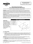
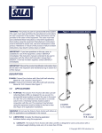
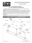
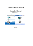
1
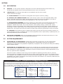
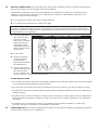
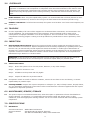
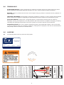
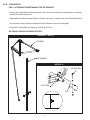
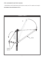
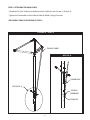
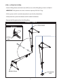
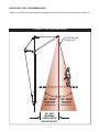
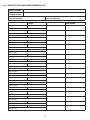
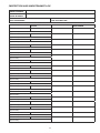
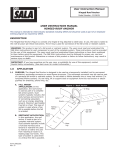
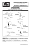
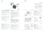
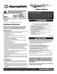
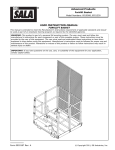
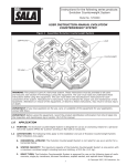
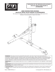
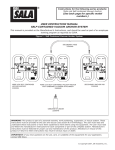
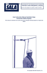
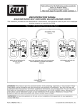
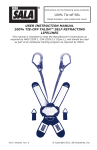
Instructions for the following product:
SKY ANCHOR SYSTEM
USER INSTRUCTION MANUAL:
SKY ANCHOR SYSTEM
WARNING: This product is part of a fall arrest or rescue system. These instructions must be provided to all
users and rescuers (see Section 8 Terminology) using this equipment. The user must read and understand
these instructions before using this equipment. The user must follow the manufacturer’s instructions for each
component of the system. Manufacturer’s instructions must be followed for proper use and maintenance of
this equipment. Alterations or misuse of this equipment, or failure to follow instructions, may result in
serious injury or death.
IMPORTANT: If you have questions on the use, care, or suitability of this equipment for your application,
contact Capital Safety.
IMPORTANT: Before using this equipment, record the product identification information from the ID label
into the inspection and maintenance log in Section 11.0 of this manual.
FIGURE 1
Form: 5903104 Rev: C
© Copyright 2013, DBI Industries, Inc.
SECTION
1.0
APPLICATION
1.1
PURPOSE: The Sky Anchor System is designed to be used in DBI Advanced Sky Anchor Bases only.
The Sky Anchor System can be used for personal fall arrest, rescue, and retrieval.
1.2
LIMITATIONS: The following limits apply to the installation and use of this system.
Other limitations may apply:
A. SYSTEM CAPACITY: The maximum working load of this system is 450 lbs. (205kg).
B. PERSONAL FALL ARREST SYSTEM: PFAS’s used with this system must meet applicable OSHA, state,
federal, and ANSI requirements. PFAS’s incorporating a full body harness must be capable of arresting a
worker’s fall with a maximum arresting force appropriate for the set up of this system.
C. ENVIRONMENTAL HAZARDS: Use of this equipment in areas where environmental hazards exist may
require additonal precautions be taken to reduce the possiblity of injury to the user or damage to the
equipment. Hazards may include, but are not limited to: heat (welding, cutting), extreme cold, caustic
chemicals, corrosive environments, high voltage power lines, explosive or toxic gases, moving machinery, or
sharp edges. Contact Capital Safety if you have questions about using this equipment where environmental
hazards exist. This system cannot be used where the davit mast cannot be perpendicular to the work surface.
D. TRAINING: This equipment must be installed and used by persons who have been properly trained in its
correct application and use. Installation and use of this equipment must be supervised by a qualified person, as
defined by OSHA fall protection standards.
1.3
APPLICABLE STANDARDS: Refer to local standards,national standards, and OSHA requirements, for more
information on the application of this and associated equipment.
2.0
SYSTEM REQUIREMENTS
2.1
COMPATIBILITY OF COMPONENTS: Capital Safety equipment is designed for use with Capital Safety
approved components and subsystems only. Substitutions or replacements made with non-approved
components or subsystems may jeopardize compatibility of equipment and may effect the safety and reliability
of the complete system.
2.2
COMPATIBILITY OF CONNECTORS: Connectors are considered to be compatible with connecting elements
when they have been designed to work together in such a way that their sizes and shapes do not cause their
gate mechanisms to inadvertently open regardless of how they become oriented. Contact Capital Safety if you
have any questions about compatiblity.
Connectors (hooks, carabiners, and D-rings) must be capable of supporting at least 5,000 lbs. (22.2 kN).
Connectors must be compatible with the anchorage or other system components. Do not use equipment that is
not compatible. Non-compatible connectors may unintentionally disengage. See Figure 2. Connectors must be
compatible in size, shape, and strength. Self locking snap hooks and carabiners are required by ANSI Z359 and
OSHA and CSA Z259.12 in Canada.
FIGURE 2 - Unintentional Disengagement (Roll-out)
If the connecting element that a snap hook (shown) or carabiner attaches to is undersized or irregular in shape, a situation could
occur where the connecting element applies a force to the gate of the snap hook or carabiner. This force may cause the gate (of
either a self-locking or a non-locking snap hook) to oopen, allowing the snap hook or carbiner to disengage from the connecting
point. For ANSI Z359.1-2007 compliant hooks, there are no restrictions on the size or shape of the mating connector provided the
snap hook is free to align with the applied load as intended.
Small ring or other noncompatibly shaped element
1. Force is applied to
the snap hook
2. The gate presses against
the connecting ring.
2
3. The gate opens allowing
the snap hook to slip off.
2.3
MAKING CONNECTIONS: Only self-locking snap hooks and/or carabiners shall be used with this equipment.
Ensure all connectors are fully closed, locked, and compatible.
Capital Safety connectors (snap hooks and carabiners) are designed to be used only as specified in each
product’s user instructions. See Figure 3 for inappropriate connections. Capital Safety snap hooks and
carabiners should not be connected:
A. To a D-ring which another connector is already attached.
B. In a manner that would result in a load on the gate.
NOTE: Large throat snap hooks should not be connected to standard size D-rings or similar objects which
will result in a load on the gate if the hook or D-ring twists or rotates, unless the snap hook complies with
ANSI Z359.1-2007 and is equipped with a 3,600 lb gate. Check the marking on your snap hook to verify that
it is appropriate for your application.
C. In a false engagement
where features that
protrude from the
snap hook or carabiner
catch on the D-ring,
and without visual
confirmation seems to
be fully engaged to the
anchor point.
FIGURE 3 - Inappropriate Connections
D. to each other.
E. Directly to webbing
or rope lanyard for
tie-back (unless
specifically provided by
the manufacturer).
F. to any object which is
shaped or dimensioned
such that the snap
hook or carabiner will
not close and lock, or where roll-out could occur.
OTHER RESTRICTIONS
• Do not make connections where the hook locking mechanism can come into contact with a structural member
or other equipment and potentially release the hook.
• Do not connect a snap hook into a loop or thimble of a wire rope or attach in any way to a slack wire rope.
• The snap hook must be free to align with the applied load as intended (regardless of the size or shape of the
mating connector).
• A carabiner may be used to connect to a single or pair of soft loops on a body support such as a body belt or
full body harness, provided the carabiner can fully close and lock. This type of connection is not allowed for
snap hooks.
• A carabiner may be connected to a loop or ring connector that is already occupied by a choker style
connector. This type of connection is not allowed for snap hooks.
2.4
STRUCTURE LOAD: The structure supporting this system must be rigid and capable of supporting a minimum
moment load of 145,000 in*lb. (16383 N*m).
3
3.0
SYSTEM USE
WARNING: Do not alter or intentionally misuse this equipment. Consult with Capital Safety if using this
equipment in combination with components or subsystems other than those described in this manual. Some
subsystems and components combinations may interfere with the proper operation of this equipment. Use
caution when using this equipment around moving machinery, electrical and chemical hazards, and sharp
edges.
3.1
BODY SUPPORT: When using this Capital Safety system it is recommended that a full body harness be worn.
For general fall protection use, connect to the D-ring on the back between the shoulders (Dorsal D-ring).
3.2
NORMAL OPERATION: If a fall has been arrested, the system must be taken out of service and inspected, see
Section 5.0.
4.0 TRAINING
4.1
It is the responsiblity of all users of this equipment to understand these instructions, and are trained in the
correct installation, use, and maintenance of this equipment. These individuals must be aware of the
consequences of improper installation or use of this equipment. This user manual is not a substitute for a
comprehensive training program. Training must be provided on a periodic basis to ensure proficiency of the
users.
5.0 INSPECTION
5.1
BEFORE EACH INSTALLATION: Inspect this system and other system components according to these or
other manufacturer’s instructions. System components must be formally inspected by a qualified person (other
than the user) at least annually. Formal inspections should concentrate on visible signs of deterioration or
damage to the system components. Items found to be defective must be replaced. Do not use components if
inspection reveals an unsafe or defective condition. Record results of each inspection in the inspection and
maintenance log in Section 11.0 of this manual.
IMPORTANT: If this equipment has been subjected to forces resulting from the arrest of a fall, it must be
immediately removed from service and destroyed or returned to Capital Safety for possible repair.
5.2
INSPECTION STEPS:
Step 1: Ensure the system is free of cracks, dents, distortion, or any other damage.
Step 2: Inspect for corrosion or rust
Step 3: All labels must be present and fully legible.
Step 4:
Inspect all cables for any broken strands.
5.3
If inspection reveals an unsafe or defective condition, remove the unit from service and destroy, or contact
Capital Safety for possible repair.
5.4
USER EQUIPMENT: Inspect each system component or subsytem (i.e. SRL, full body harness, lanyard, lifeline,
etc.) per associated manufacturer’s instructions. Refer to manufacturer’s instruction supplied with each system
component for inspectoin procedure.
6.0 MAINTENANCE, SERVICE, STORAGE
6.1
This system requires no scheduled maintenance, other than repair or replacement of items found defective
during inspection; see Section 5.0. If components become heavily soiled with grease, paint, or other
substances, clean with appropriate cleaning solutions. Do not use caustic chemicals that could damage system
components.
7.0 SPECIFICATIONS
7.1
MATERIALS:
General Construction
Structure Material
Finish
Welded Steel & Aluminum
A36 Steel,6061-T6/7075-T6 Aluminum
Zinc Plate Per ASTM B633, Safety Yellow Powdercoat
4
5
1 PERSON
TM
9507943 REV A
THIS SYSTEM MEETS OR EXCEEDS ALL
APPLICABLE OSHA STANDARDS.
75
USER CAPACITY IN ACCORDANCE WITH
MANUFACTURER’S INSTRUCTIONS. FAILURE TO
COMPLY MAY RESULT IN SERIOUS INJURY OR
DEATH.
pn
THIS MAN-RATED SYSTEM IS DESIGNED FOR A
MAXIMUM OF
A R# 1 5 7 N
NI
in
6FT MAX
WORKING
RADIUS FROM
ANCHOR POINT
(8 k N
l b h or Po ) R
nc
SAFE WORKING
ANGLE FROM
ANCHOR POINT
The following labels must be present and fully legible:
G
9.1
30° MAX
SELF RETRACTING
LIFELINE (SRL)
A
180
0
FIGURE 1
• SUPPORTING STRUCTURES FOR THIS SYSTEM MUST
BE CERTIFIED AND CAPABLE OF SUPPORTING THE
ENTIRE WEIGHT OF THE CONFIGURED SYSTEM ALONG
WITH ANY LOADS THAT COULD POTENTIALLY BE
INTRODUCED IN THE EVENT OF ARRESTING A FALL.
• IF YOU HAVE ANY QUESTIONS OR CONCERNS ON
THE USEAGE, CARE, OR SUITABILITY OF THIS
EQUIPMENT, PLEASE CONTACT CAPITAL SAFETY
BEFORE USING IT.
• BE CAUTIOUS OF OVERHEAD POWER LINES OR
OTHER ELECTRIC SOURCES WHICH CAN CAUSE
ELECTRIC SHOCK.
• DO NOT EXCEED THE SAFE WORKING RADIUS OF 6’
OR WORKING ANGLE OF 30˚(WHICHEVER COMES
FIRST) AS SHOWN IN FIGURE 1. FAILURE TO WORK
WITHIN THE SAFE WORKING AREA MAY CAUSE SERIOUS
INJURY OR DEATH.
• NO MORE THAN ONE PERSON IS ALLOWED TO BE
ATTACHED TO THE ANCHOR POINT AT ANY GIVEN TIME.
MODEL NO.:
• DO NOT EXCEED THE MAXIMUM NUMBER OF USERS
RATING.
• MATERIAL HANDLING DEVICES USED WITH THIS
PRODUCT MUST NOT EXCEED 450 LB. (205 kg).
LABELING
ed
• RETRACTABLE DEVICES AND SHOCK ABSORBERS
USED WITH THIS PRODUCT MUST HAVE AN AVERAGE
ARRESTING FORCE OF NOT GREATER THAN 900 LB
(4 KN) AND MEET ANSI Z359.14 TYPE B OR Z359.13
RESPECTIVELY. REFER TO RETRACTABLE DEVICES OR
SHOCK ABSORBERS LABELING TO DETERMINE
MAXIMUM ALLOWED USER WEIGHT.
LOT NO.:
t
WARNING
MFRD(Y/M):
• ALL USERS MUST READ AND UNDERSTAND THE
INSTRUCTIONS PRIOR TO USING THIS SYSTEM.
9.0
at
OPERATORS INSTRUCTIONS
W
SKY ANCHOR SYSTEM
8.0
TERMINOLOGY
AUTHORIZED PERSON: A person assigned by the employer to perform duties at a location where the person
will be exposed to a fall hazard (otherwise referred to as “user” for the purpose of these instructions).
RESCUER: Person or persons other than the rescue subject acting to perform an assisted rescue by operation of
rescue system.
CERTIFIED ANCHORAGE: An anchorage for fall arrest, positioning, restraing, or rescue systems that a qualified
person certifies to be capable of supporting the potential fall forces that could be encountered during a fall.
QUALIFIED PERSON: A person with a recognized degree or preofessional certificate and with extensive
knowledge, training, and experience in the fall protection and rescue field who is capable of designing, analyzing,
evaluating and specifying fall protection and rescue systems to the extent required by this standard.
COMPETENT PERSON: One who is capable of identifying existing and predictable hazards in the surroundings
or working conditions which are unsanitary, hazardous, or dangerous to employees, and who has authorization to
take prompt corrective measures to eliminate them.
9504547
www.capitalsafety.com
(800) 328-6146
SERIAL NO.
LENGTH(FT):
10.0 SYSTEM SETUP
STEP 1- ATTACHING THE BOTTOM MAST TO THE TOP MAST:
- Remove the Top & Bottom Mast components from the crate, and remove the protective wrapping
material from the components.
- Slide the Bottom Mast into the Top Mast until the cap screw is seated in the slot of the Bottom Mast.
- Line up holes in the Top Mast and Bottom Mast and fasten using the Locking Bolt.
- Torque the Locking Bolt to a minimum of 45 ft*lb (61 N*m).
SEE FIGURE 4 FOR ILLUSTRATIONS OF STEP 1.
FIGURE 4 - STEP 1
TOP MAST
BOTTOM MAST
DETAIL A
LOCKING BOLT
CAP SCREW
SLOT
6
STEP 2- UNFOLDING TOP MAST OF SKY ANCHOR:
- Unfold the Boom and Tie-Back Bracket of the Top Mast assembly until the cables are straight.
SEE FIGURE 5 FOR ILLUSTRATIONS OF STEP 2.
FIGURE 5 - STEP 2
BOOM
TIE-BACK
BRACKET
7
STEP 3- ATTACHING TIE-BACK CABLE:
- Attach the Tie-Tack Taribiner to the Bottom Mast Cable Eye as shown in Detail A.
- Tighten the Turnbuckle on the Tie-Back Cable to 400 lb (181kg) of tension.
SEE FIGURE 6 FOR ILLUSTRATIONS OF STEP 3.
FIGURE 6 - STEP 3
TIE-BACK CABLE
DETAIL A
TURNBUCKLE
SEE DETAIL A
TIE-BACK
CARABINER
CABLE EYE
8
STEP 4 - LIFTING THE SYSTEM:
- Secure a lifting device (overhead crane, forklift, or etc.) to the Lifting Ring as shown in Detail A.
- IMPORTANT: Lifting device must have a minimum capacity of 500 lb (227 kg).
- Lift the system until it is vertical and position it over the Sky Anchor Base.
- Gently lower the system into the base until it reaches the bottom.
- Remove the lifting device from the Lifting Ring.
FIGURE 7 - STEP 4
LIFTING DEVICE
DETAIL A
LIFTING
RING
SEE DETAIL A
SKY ANCHOR
BASE
9
USER INSTRUCTION: SAFE WORKING AREA
- Make sure to follow the safe working area when using the Sky Anchor system as shown in Figure 8.
FIGURE 8 - SAFE WORKING AREA
SELF RETRACTING
LIFELINE (SRL)
30° MAX
SAFE WORKING
ANGLE FROM
ANCHOR POINT
6FT MAX
WORKING
RADIUS FROM
ANCHOR POINT
10
30° MAX
SAFE WORKING
ANGLE FROM
ANCHOR POINT
11.0 INSPECTION AND MAINTENANCE LOG
SERIAL NUMBER:
MODEL NUMBER:
DATE PURCHASED:
INSPECTION DATE
DATE OF FIRST USE:
INSPECTION ITEMS
NOTED
CORRECTIVE ACTION
Approved By:
Approved By:
Approved By:
Approved By:
Approved By:
Approved By:
Approved By:
Approved By:
Approved By:
Approved By:
Approved By:
Approved By:
Approved By:
Approved By:
Approved By:
Approved By:
Approved By:
Approved By:
11
MAINTENANCE
PERFORMED
INSPECTION AND MAINTENANCE LOG
SERIAL NUMBER:
MODEL NUMBER:
DATE PURCHASED:
INSPECTION DATE
DATE OF FIRST USE:
INSPECTION ITEMS
NOTED
CORRECTIVE ACTION
Approved By:
Approved By:
Approved By:
Approved By:
Approved By:
Approved By:
Approved By:
Approved By:
Approved By:
Approved By:
Approved By:
Approved By:
Approved By:
Approved By:
Approved By:
Approved By:
Approved By:
Approved By:
12
MAINTENANCE
PERFORMED
INSPECTION AND MAINTENANCE LOG
SERIAL NUMBER:
MODEL NUMBER:
DATE PURCHASED:
INSPECTION DATE
DATE OF FIRST USE:
INSPECTION ITEMS
NOTED
CORRECTIVE ACTION
Approved By:
Approved By:
Approved By:
Approved By:
Approved By:
Approved By:
Approved By:
Approved By:
Approved By:
Approved By:
Approved By:
Approved By:
Approved By:
Approved By:
Approved By:
Approved By:
Approved By:
Approved By:
13
MAINTENANCE
PERFORMED
INSPECTION AND MAINTENANCE LOG
SERIAL NUMBER:
MODEL NUMBER:
DATE PURCHASED:
INSPECTION DATE
DATE OF FIRST USE:
INSPECTION ITEMS
NOTED
CORRECTIVE ACTION
Approved By:
Approved By:
Approved By:
Approved By:
Approved By:
Approved By:
Approved By:
Approved By:
Approved By:
Approved By:
Approved By:
Approved By:
Approved By:
Approved By:
Approved By:
Approved By:
Approved By:
Approved By:
14
MAINTENANCE
PERFORMED
INSPECTION AND MAINTENANCE LOG
SERIAL NUMBER:
MODEL NUMBER:
DATE PURCHASED:
INSPECTION DATE
DATE OF FIRST USE:
INSPECTION ITEMS
NOTED
CORRECTIVE ACTION
Approved By:
Approved By:
Approved By:
Approved By:
Approved By:
Approved By:
Approved By:
Approved By:
Approved By:
Approved By:
Approved By:
Approved By:
Approved By:
Approved By:
Approved By:
Approved By:
Approved By:
Approved By:
15
MAINTENANCE
PERFORMED
LIMITED LIFETIME WARRANTY
Warranty to End User: D B Industries, Inc., dba CAPITAL SAFETY USA (“CAPITAL SAFETY”) warrants to the
original end user (“End User”) that its products are free from defects in materials and workmanship under
normal use and service. This warranty extends for the lifetime of the product from the date the product is
purchased by the End User, in new and unused condition, from a CAPITAL SAFETY authorized distributor.
CAPITAL SAFETY’S entire liability to End User and End User’s exclusive remedy under this warranty is limited
to the repair or replacement in kind of any defective product within its lifetime (as CAPITAL SAFETY in its sole
discretion determines and deems appropriate). No oral or written information or advice given by CAPITAL
SAFETY, its distributors, directors, officers, agents or employees shall create any different or additional
warranties or in any way increase the scope of this warranty. CAPITAL SAFETY will not accept liability for defects
that are the result of product abuse, misuse, alteration or modification, or for defects that are due to a failure to
install, maintain, or use the product in accordance with the manufacturer’s instructions.
CAPITAL SAFETY’S WARRANTY APPLIES ONLY TO THE END USER. THIS WARRANTY IS THE ONLY WARRANTY
APPLICABLE TO OUR PRODUCTS AND IS IN LIEU OF ALL OTHER WARRANTIES AND LIABILITIES, EXPRESSED
OR IMPLIED. CAPITAL SAFETY EXPRESSLY EXCLUDES AND DISCLAIMS ANY IMPLIED WARRANTIES OF
MERCHANTABILITY OR FITNESS FOR A PARTICULAR PURPOSE, AND SHALL NOT BE LIABLE FOR INCIDENTAL,
PUNITIVE OR CONSEQUENTIAL DAMAGES OF ANY NATURE, INCLUDING WITHOUT LIMITATION, LOST PROFITS,
REVENUES, OR PRODUCTIVITY, OR FOR BODILY INJURY OR DEATH OR LOSS OR DAMAGE TO PROPERTY, UNDER
ANY THEORY OF LIABILITY, INCLUDING WITHOUT LIMITATION, CONTRACT, WARRANTY, STRICT LIABILITY, TORT
(INCLUDING NEGLIGENCE) OR OTHER LEGAL OR EQUITABLE THEORY.
The Ultimate in Fall Protection
CSG USA & Latin America
3833 SALA Way
Red Wing, MN 55066-5005
Distributed by Engineered Fall Protection
Email: [email protected]
Web: www.engineeredfallprotection.com
PH: 314-492-4422 | FAX: 800-570-5584
I S O
9001
Certificate No. FM 39709