1
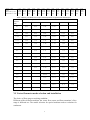
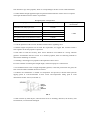
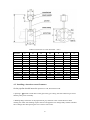
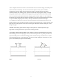
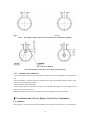
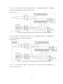
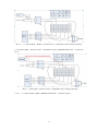
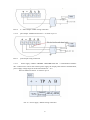
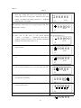
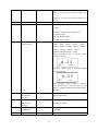
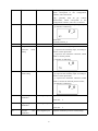
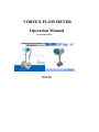
VORTEX FLOWMETER Operation Manual Version:2012-6V01 2012.06 1 I. Summary Vortex Flowmeter is one kind of main flowmeters in the international for detection and metering the liquid, gas and steam. It is widely used in Petroleum, chemical, metallurgy, heat supply industry, etc. Features: Detecting element does not touch with flow medium, with high reliability yand strong flexibility for medium No moving parts, wear resistance, structure is simple and fastness Good earthquake resistance The allowed working temperature is wide from -40℃ to +350℃ Wide range, High accuracy Pulse signal output or two-wire system 4-20mA current signal output Ⅱ. Working principle Setting a triangular prism vortex generator in the flowmeter, regular vortex will be generated at both the sides of triangular prism, which is called Karman swirl. As showed on the drawing 1.1, vortex are arranged regularly at the downstream of vortex generator. Suppose the vortex generation frequency is F, the average flow velocity of medium is V, d is the width of the surface of triangular prism incident flow, and D for the nominal diameter of flowmeter. Then we get the computation formula: PIC 1: The working principle of Vortex flowmeter III. Basic Parameter Measured Medium Medium Temp. Liquid, Gas, Steam -40~+200℃;-40~+280℃;40~+350℃ 2 Nominal Pressure 1.6MPa;2.5MPa;4.0MPa;64MPa(Other pressure can be custom) Accuracy ±1.0%,±1.5% Measuring range ratio 1:8-1:30(Standard air condition as reference), 1:8-1:40(Normal Temperature as reference) Flow range Liquid:0.4-7.0m/s; Gas:4.0-60.0m/s; Steam:5.0-70.0m/s Specifications DN15~DN600 Material 1Cr18Ni9Ti Reynolds number Normal Resistance coefficient Cd≦2.6 Vibration acceleration LUGB≦0.2g allowed Ex-proof class IP65 ExiaIICT6 Ga Ambient Temp. Ambient condition -40℃-65℃(Non Display on site); -20℃-55℃(Display on site) Relative humidity ≦5%~93% Pressure 86-106kPa Power Supply 12-24V/DC or 3.6V battery powered Pulse frequency signal2-3000Hz,Low level≦1V,high level≧6V Signal Output Two-wire system 4-20 signal(isolated output),Load≦500 3.1 Flow Range Full tube vortex flowmeter measuring range (Check table 1,table2,table 3,table 4) Table 1: Vortex flowmeter for gas: Diame ter mm Meter factor/m3 15 Normal Gas and Steam Measuring range m³/h Frequency Setting Hz CH Selection Amplificati on factor 350000 3-50 300~3900 CH3 500 20 145000 5-80 200~3000 CH3 500 25 80000 6-120 150~2500 CH3 500 32 35000 10-150 100~2200 CH3 500 40 19000 16-320 80~2000 CH3 500 50 9100 25-500 50~1200 CH3 500 65 4260 40-800 40~900 CH3 500 80 2300 60-1250 30~800 CH3 500 3 40 19000 16-320 80~2000 CH3 500 50 9100 25-500 50~1200 CH3 500 65 4260 40-800 40~900 CH3 500 80 2300 60-1250 30~800 CH3 500 100 1200 100-2000 25~600 CH3 500 125 580 150-3000 20~500 CH3 500 150 345 200-4500 15~400 CH3 500 200 145 300-8000 10~320 CH3 500 250 73 500-12000 8~240 CH3 500 300 43 800-18000 7~200 CH3 500 350 27 1000-24000 6~180 CH3 500 400 18 1500-30000 5~150 CH3 500 450 13 2000-40000 4~130 CH3 500 500 9 2500-50000 4~120 CH3 500 600 5 3000-70000 3~100 CH3 500 Table 2: The flow range of vortex flowmeter for liquid. Size mm Meter factor/m3 15 Liquid(Water) Measuring range m³/h Frequency Setting Hz CH Selection Amplificati on factor 350000 0.8-9 40~800 CH2 500 20 145000 1.2-15 30~600 CH2 500 25 80000 2-18 18~360 CH2 500 32 35000 2.5-30 15~300 CH2 500 40 19000 3 -48 10~250 CH2 500 50 9100 5-75 9~190 CH2 500 65 4260 8-120 8~160 CH2 500 80 2300 14-180 51~20 CH2 500 100 1200 22-300 4~100 CH2 500 125 580 40-450 3~90 CH2 500 150 345 56-660 2~60 CH2 500 200 145 100-1200 2~50 CH2 500 250 73 150-1800 2~40 CH2 500 300 43 200-2500 2~35 CH2 500 350 27 280-3500 1~30 CH2 500 400 18 380-4500 1~25 CH2 500 450 13 480-6000 1~20 CH2 500 500 9 600-7000 1~18 CH2 500 600 5 800-10000 1~15 CH2 500 4 Abs Pre.P(Mpa) Temp.T(℃) Density kg/m³ 0.2 120.2 1.129 0.3 133.5 1.651 0.4 143.62 2.163 0.5 151.84 2.669 DN20 Qmin QMax Measurable Up Limit Measurable Low Limit 9 60 80 9 11Table 83 102 11 12 3: The 108 130 12 DN25 Qmin QMax Measurable Up Limit Measurable Low Limit 14 93 136 14 17 133 198 17 DN40 Qmin QMax Measurable Up Limit Measurable Low Limit 35 233 400 32 DN50 Qmin QMax Measurable Up Limit Measurable Low Limit 0.6 158.94 3.170 0.7 158.94 2.669 1.4 195.04 7.106 1.6 201.37 8.085 1.8 207.11 9.065 2.0 212.37 10.05 13 15 of vortex 16 17 18for saturated 19 20 flow range flowmeter steam. 134 160 13 158 190 15 183 220 16 208 250 17 233 279 18 257 309 19 306 368 20 22 355 426 22 24 404 485 24 25 453 544 25 26 503 603 26 19 173 260 19 21 215 320 21 23 254 380 23 25 293 440 25 27 333 499 27 28 372 559 28 30 412 618 30 33 490 735 33 35 568 853 35 37 647 970 37 39 725 1088 39 42 804 1206 42 42 332 498 38 48 433 649 44 54 534 801 48 59 634 951 53 63 733 1100 57 67 832 1249 60 71 931 1397 64 75 1029 1544 67 82 1225 1838 73 88 1421 2132 79 94 1617 2426 84 99 1813 2720 89 104 2010 3015 94 52 400 667 52 64 498 826 64 73 649 1080 73 81 801 1335 81 88 951 1585 88 95 1100 1834 95 100 1249 2081 100 107 1397 2328 107 112 1544 2574 112 122 1838 3054 122 132 2132 3553 132 140 2426 4043 140 149 2720 4533 149 157 3015 5025 157 DN65 Qmin QMax Measurable Up Limit Measurable Low Limit 88 667 933 88 106 826 1320 106 121 1080 1730 121 135 1335 2135 135 147 1585 2536 147 158 1834 2934 158 168 2081 3330 168 178 2328 3724 178 187 2574 4118 187 204 3054 4902 204 220 3553 5685 220 234 4043 6468 234 248 4533 7252 248 261 5025 8040 261 DN80 Qmin QMax Measurable Up Limit Measurable Low Limit 140 1166 1400 105 170 1650 1980 127 194 2160 2596 145 215 2700 3240 161 235 3170 4015 176 252 3660 4644 189 269 4160 5270 201 284 4655 5896 213 299 5150 6520 224 326 6130 7760 345 350 7100 9000 263 375 9080 10240 280 397 9060 11480 298 418 10000 12730 313 DN100 Qmin QMax Measurable Up Limit Measurable Low Limit 175 1166 2332 175 212 1650 3300 212 242 2160 4320 242 269 2700 5400 269 293 3170 6430 293 315 3660 7320 315 336 4160 8320 336 355 4655 9310 355 374 5150 10300 374 408 6130 12260 408 439 7100 14200 439 468 8080 16160 468 496 9060 19120 496 522 10050 20100 522 DN125 Qmin QMax Measurable Up Limit Measurable Low Limit 262 1866 3500 262 317 2640 4950 317 363 3460 6490 363 404 4270 8000 404 440 5070 9510 440 473 5870 11000 473 504 6660 12500 504 533 7450 14000 533 560 8240 15440 560 611 9800 18400 611 658 11370 21300 658 702 12940 24260 702 744 14500 27200 744 783 16080 30200 783 DN150 Qmin QMax Measurable Up Limit Measurable Low Limit 437 292 4666 350 529 4130 6600 423 605 5408 8650 484 673 6670 10680 538 733 7930 1268 586 788 9170 14670 631 840 10400 16650 672 888 11640 18620 711 934 12870 20590 747 1091 15320 24500 815 1097 17770 28420 878 1171 20210 32340 936 1239 66000 36260 990 1305 25120 40200 1044 DN200 Qmin QMax Measurable Up Limit Measurable Low Limit 700 4666 9330 610 847 6600 13200 740 969 8650 17300 848 1076 10680 21360 942 1173 12680 25360 1026 1261 14670 29340 1104 1344 16650 33300 1176 1421 18620 37240 1243 1494 20590 41180 1308 1630 24500 47000 1427 1756 28420 56850 1536 1873 32240 64680 1638 1983 36260 72520 1735 2088 40200 80400 1827 DN250 Qmin QMax Measurable Up Limit Measurable Low Limit 1050 6998 13997 875 1270 9906 19810 1056 1614 12980 25960 1210 1759 16010 32030 1345 1892 19020 38040 1466 2016 22000 44000 1577 2132 24970 49940 1680 2241 27930 55860 1776 1446 30880 61760 1868 2634 36760 73520 2038 2808 42640 85270 2195 1453 48500 97000 2340 2975 54390 3132 60300 108780 120600 2480 2610 5 0.8 170.41 4.162 0.9 175.36 4.665 1.0 179.68 5.147 1.2 187.96 6.127 DN300 Qmin QMax Measurable Up Limit Measurable Low Limit 1750 11664 20995 1050 2116 16510 29720 1270 2422 21630 38930 1453 2690 26690 48040 1614 2932 31700 57050 1759 3153 36670 66000 1892 3359 41620 74900 2016 3550 46550 83800 2132 3736 51470 92650 2241 4076 61270 4389 71010 4682 80850 110300 127900 145530 2446 2634 2808 4958 90650 16320 2975 Table 4:Density and Relative Pressure and Temperature of superheated steam(Kg/m³) Absolute Temperature(℃) pressure 150 200 250 300 350 400 MPa 0.1 0. 5 2 0.4 6 0.42 0.38 0.. 1 5 0. 7 8 0.7 0 0.62 0.57 0.52 0.49 0.2 1. 0 4 0.9 3 0.83 0.76 0.69 0.65 0.. 2 5 1. 3 1 1.1 6 1.04 0.95 0.87 0.81 0. 3 3 1. 5 8 1.3 9 1.25 1.14 1.05 0.97 0. 3 5 1. 8 5 1.6 3 1.46 1.33 1.22 1.13 0.4 2. 1 2 1.8 7 1.68 1.52 1.40 1.29 0.5 2.3 5 2.11 1.91 1.75 1.62 0.6 2.8 4 2.54 2.30 2.11 1.95 0.7 3.3 3 2.97 2.69 2.46 2.27 0.8 3.8 3 3.41 3.08 2.82 2.60 1..0 4.8 6 4.30 3.88 3.54 3.26 1.2 5.9 1 5.20 4.67 1.5 7.5 5 6.58 5.89 5.36 4.93 2.0 8.968 7.97 7.21 6.62 2.5 11.5 10. 1 9.11 3.0 14. 2 12. 3 11.1 10. 1 3.5 17. 0 14. 6 13.0 11.8 17. 0 15.1 13. 6 4.0 4.26 3.92 8.33 VI. Vortex flowmeter mode selection and installation The choice of flow range at working condition: Different caliber, different medium, the vortex flow sensor and flow transmitter’s flow range is different too. The model selection for special medium needs to calculate for settlement. 6 5220 10050 180900 3132 4.1 The choice for Gas flow range The upper limit of vortex flowmeter does not influenced by the temperature and pressure of medium. Flow range is depended on the medium’s density and viscosity at working condition. Thus, the confirmation of flow range is calculation the available lower limit flow. Calculation 1:First of all, using formula to calculate the working condition lower limit flow, which is determined by viscosity In the formula: :The medium’s lower limit flow at working condition density Qo: The lower limit flow of flowmeter at reference condition : Reference the air density, =1.205kg/m³ : Working condition density of medium to be measured Calculation 2 Qv formula for calculation the lower flow limit by kinematic viscosity In the formula: Qv : Lower limit flow of the medium Qo: Low flow limit at reference condition Vo: Reference viscosity,15kgm/S² V: The working condition viscosity of medium(kgm/S²) Compare Qo and Qv, the larger flow as the real low flow limit of gas. 4.1.1 The choice for liquid flow range As shown on flow range table 2 4.1.2 The choice of steam flow range Saturated steam: Reference to table 3 to choose Superheated steam: Through table 4 to get the pressure, temperature and corresponding density, taking the similar density’s flow range from table six to confirm the flow range of superheated steam. 4.2 Installation Condition 4.2.1Flow sensor should be horizontal or vertical installed(the liquid flow direction should be 7 from bottom to top) on the pipeline, which is corresponding to the flow sensor nominal diameter. 4.2.2The definite straight pipeline length at upstream and downstream of flow sensor is required. The length should meet below table’s requirements: Straight Pipeline Configuration Upstream Straight pipe form The Straight length of upstream Concentric tube fully open valve ≧12DN Concentric contraction fully open valve ≧15DN Single quarter bend ≧20DN Two quarter bends on the same surface ≧25DN Two quarter bends on the different surface ≧40DN Regulating valve、Half-open gate valve ≧50DN The Straight length of downstream ≧5DN 4.2.3At the upstream of flow sensor should not install a flow regulating valve. 4.2.4If the length of upstream can not meet the requirement, we suggest that customer install a flow regulator at the side pipeline of upstream. 4.2.5In order to avoid the accuracy, Flow sensor should be not installed on a strong vibration pipeline. If installation the flow sensor on a vibration pipeline, there are following methods to decrease the disturbing of vibration: A. Installing a fixed support on pipeline at 2D upstream of flow sensor. B. At the condition of meeting the straight length, install a hosepipe as a transmission. 4..2.6 Installation flow sensor on high temperature pipeline, if the heat preservation not good, the flow sensor should be installed downward vertical. 4..2.7When the amendment is needed for temperature and pressure,it should install pressure tapping points at 3-5D downstream of flow sensor and temperature taking point at 5-8D downstream of flow sensor.(As the PIC 2) PIC 2 4.2.8No collision by hard subject, when the flow sensor is installing, otherwise, the accuracy will be influenced, even flowmeter damaged. 8 Concentric Reducers Pipeline Concentric Reducers Pipeline Concentric expansion pipeline Concentric expansion pipeline Single quarter bend Single quarter bend Two quarter bends on the same surface Two quarter bends on the same surface Two quarter bends on the different surface Two quarter bends on the different surface Regulating valve 、 Half-open gate valve Pic 3 :Normal Pipeline 图2 Regulating valve 、 Half-open gate valve PIC 4 : With图 3 rectifier flow 4.2.9 Overall Size Overall Size check the PIC 5 and table 5 9 Table 5:Overall size of vortex flowmeter(mm) Diameter L1 L2 D1 D2 H D3 N DN15 DN20 DN25 DN40 DN50 DN65 DN80 DN100 DN125 DN150 DN200 DN250 DN300 65 65 65 75 75 75 80 90 100 120 150 160 170 95 95 95 109 109 117 122 132 146 170 200 214 224 125 125 125 145 160 180 195 230 245 280 335 405 460 100 100 100 110 125 145 160 190 210 240 295 355 410 460 460 460 470 480 497 510 544 564 594 646 708 760 14 14 14 18 18 18 18 18 18 22 22 22 22 4 4 4 4 4 4 8 8 8 8 12 12 12 4.3 Installing a insertion vortex flowmeter On the pipeline should insure the upstream≧15D, downstream≧5D 1.Opening a 100mm circular hole on the pipe line by gas cutting. the hole without rag to insure that the probe passes smoothly. 2.Welding flange short tube on the pipeline hole, pay attention to the vertical direction when welding. the effect after welding requires the axis and pipeline axis orthogonality and the extended line of flange short tube passing the cross-section circle center. 10 3.The Y length of Insertion rod below vortex flowmeter down connection flange, should be prevail to the real external workshop. The users do not need to adjust it. In the special condition, computing the insertion depth should consider the length of straight pipeline and working condition medium, then making proper adjustment. When the straight pipeline length is enough and pipeline diameter above 400mm,can adopting average flow spot measurement, this method does not influence by the Reynolds number changing, probe insertion depth is 1/4D-1/3D(D for the diameter of pipeline).When the pipeline straight length is short and pipeline diameter less than or equal to 400mm,adopting center velocity flow spot measurement, the insertion depth Y=0.5D(Reference drawing 6).After the measurement depth confirmed, adjusting insertion rod length, settling erosion point direction mark to make sure that the direction of vortex generator and flow direction in the pipeline is same, then connecting the flowmeter and bolts fixed joint on the flange short pipe. 4.Should install sealing gasket between flanges, rubber plate for normal temperature, high temperature can adopt the asbestos pad etc. heat-resisting material. 5.Assembling and dissembling method at the condition of non flow cutoff(with ball valve),when disassembling, first unscrewing stopper screw, then loosening the lock nut, pushing insertion rod upward until the probe is located the limiting position of ball valve top, now ball valve is closed. Then dissembling the top connecting flange, bolt and nut, finally taking the flowmeter away. The process of assembling is opposite to dissembling. Right Wrong 11 Right Wrong PIC 6 The flange position of Insertion Vortex Flowmeter installed on pipeline. PIC 7 Insertion Position (Insertion Depth is according to reservation real calibration) 4.3.1 Attention for installation: 1.The flow direction must be same as the flow indication rod, strictly forbidden to wrench the flow rod; 2.Flow transmitter is seted according to medium, flow range and nominal diameter, before using, it must inspect the parameter setting. 3.Removing burr and welding slag. 4.After wiring, make sure the flow converter cover and lead collar tight, in order to make sure the water proof and moisture proof. 5.Make sure that the shell of vortex flowmeter and lead shielding layer well grounded. Ⅴ.User Instruction of Local Display Vortex Flow Transmitter. 5.1. Summary: Our company’s vortex flowmeter flow transmitter panel mainly include UZ3036、UZ3024.That is 12 4-20mA,Pulse output,HART,RS485,Temperature and pressure compensation function, etc, which can be choosen by the customer. 5.2. Power Supply:12V~32V DC/3.6V battery(Optional) Power influence:Not more than 0.01%/V; The change of output loading: Not more than0.05%( 50~1000 ohm,Low limit and flow range variable quantity) Working Temperature:-20℃~+70℃(With backlit LCD dislay); -40℃~+85℃(Without LCD Display); 5.3 Main function Output and communication:4~20mA,pulse output,HART,RS485 interface (Optional) ; Configuration: Engineering units, measured medium, medium density, range ,display, alarm, etc Configuration; And with the cumulative flow reset function; Alarm function:Set the alarm upper and lower limit. below the lower limit output 3.8mA; above the upper limit output 22mA. Monitoring the dynamic variable function: instantaneous flow, precent, current output, accumulated flow, frequency, temperature, pressure etc. Flow demarcate function:The instrument coefficient K value can be 2 ~ 5 point correction On the configuration features: the engineering unit, measured medium, medium density, range, display and alarm value configuration and have reset for the accumulated flow ,data recovery function ; LCD display function:with back-light, tape symbol , double row shows. The first behavior 6 digit LCD display, can be display the instantaneous flow. The second behavior 8-bit digital display, can be display the accumulated flow, percentage, output current, temperature, pressure, density value, etc. At the same time on the LCD screen can also display a variety of engineering unit. Temperature pressure compensation function:support the two-point temperature calibration and two-point pressure calibration. Temperature and pressure can be set to manual input or automatic acquisition (optional) Data backup and recovery:the manufacturer can be backup of the configuration information such as the range before it leave the factory, the user scene illegally adjust the instrument can not work normally,damping input"005678" can be restored to the factory Instrument has the function of power-fail protection and flow accumulation. 5.4 Wiring connection 5.4.1Terminal board wiring instructions several common wiring modes as follows: 13 5.4.1.1 power supply+pressure sensor+temperature sensor ( H880TBR board card, H880BR board card without temperature-pressure compensation) as shown in pic 8 PIC 8 power supply+pressure sensor+temperature sensor wiring connection 5.4.1.2 power supply + pulse output + pressure sensor( H880TBR board card, H880BR board card without temperature-pressure compensation) as shown in pic 9 PIC 9 5.4.1.3 power supply + pulse output + pressure sensor wiring connection 4 ~ 20mA output + HART + pressure sensor + temperature sensor ( H880TH board card),as shown in pic 10 14 PIC 10 4~20mA output + HART + pressure sensor + temperature sensor wiring connection 5.4.1.4 pulse output + pressure sensor + temperature sensor ( H880TH board card),as shown in pic 11 PIC 11 pulse output + pressure sensor + temperature sensor wiring connection 5.4.1.5 4~20mA output+ HART(H880WJ board card) ,as shown in pic 12 15 PIC 12 4~20mA output+ HART wiring connection 5.4.1.6 pulse output(H880WJ board card),as shown in pic 13 PIC 13 pulse output wiring connection 5.4.1.7 Power supply + RS485(H880BR、H880TBR board card )communication interface XF3 socket used to connect the external power supply, the output pulse and 485 communication, power supply voltage range for the board card DC12V ~ 30 v. XF3 are defined as follows: as shown in pic 14 PIC 14 Power supply + RS485 wiring connection 16 6.4.2 Sensor Wiring Illustration 6.4.2.1 Vortex Flowmeter Sensor Vortex flowmeter sensor insert into socket (2p terminal )of H880 vortex flowmeter board card. 6.4.2.2 Pressure Sensor Pressure sensor connect with the main board socket I+, I-, A+, A- of XF3, I+ , I- used for connecting the power supply input terminal of sensor, A+, A - is the sensor signal output terminal. It requires the bridge circuit impenance of pressure sensor better around 3~6K Ω. This circuit power supply current for spread silicon sensor is around 0.3mA, it is applicable if the sensor input not exceed [email protected]. Socket XF3 definition as below: see PIC 15 PIC 15 Pressure Sensor Connection 6.4.2.3 Temperature Sensor Temperature sensor adopt PT1000, Two-wire connection applicable, connect with the T+ and T- of the XF5, see PIC 16. PIC 16 Temperature Sensor Connection Installation instruction: Main circuit board should connect the shell dependable (aim to connect the earth dependable), then carry out the test! 6.5 Display Interface LCD Overall display interface as below: See PIC 17 17 PIC 17 The above line display instantaneous flow while display is normal. The bottom line display accumulated flow, see PIC 18 Under normal display condition, set the display frequency, pressure, temperature, density, current, percentage at the bottom line through short press key M. PIC 18 The bottom line display virable quantity distinguish by indictor sign, see table 7 C Indictor Sign Σ Display virable quantity Accumulated flow Table 7 Frequency Indictor Sign Density Pressure Temperature Current Percentage Other display Illustration : If start write-protection, the LCD left corner show If the measure value lower than alarm limit, blink & display “↓” If the measure value higher than alarm limit, blink & display “↑” If start collecting pressure automatically, and pressure signal abnormal( sensor fault), 。 blink & display “←” if start collecting pressure automatically, and the pressure signal abnormal(sensor fault), blink & display “→” 6.6 HART Configuration Illustration Connect the flowmeter according to PIC 19. PIC 19 Vortex Flowmeter and HART connection schematic diagram HART CONFIGURATION ILLUSTRATION 18 Notice: MUST ITEM MUST CARRY OUT, EASY FORGET OR MISTAKE ITEM. 6.7 Flowmeter Button apply While use the button, suggest follow the below operation process. 19 Notice: 1. MUST ITEM MUST CARRY OUT, EASY FORGET OR MISTAKE ITEM. 2. NO. “52”、“04”means need seted menu, display on the left corner of LCD. 6.8 Flowmeter button function detailed illustration 6.8.1 Button basic function illustration Flowmeter is “three button” operate mode, the basic function of three button as PIC 20: 20 PIC 20 Three button basic function 6.8.2 Flowmeter entrance & exit 6.8.2.1 Entrance configuration Under “NORMAL WORK” condition, press “Z”, enter “ CONFIGURATION” condition. “CONFIGURATION” parameter can set by “ NO. INPUT DIRCETLY” and “ MENU CHOICE”. 6.8.2.2 Exit configuration Under “CONFIGURATION” condition, press “Z”, exit “CONFIGURATION”, enter “ NORMAL WORK” condition. NOTICE: This flowmeter record last time exit button set condition, press “Z” can return to the last time exit condition. 6.8.3 Parameter setting Site setting parameter has two types, first is “ NO INPUT DIRECTLY” and “ MENU CHOICE”. 6.8.3.1 “ NO. INPUT DIRECTLY” setting method. Press key M until it blink, it can change the setup. Press key M shortly, switch the sign. Press key S, shifting ,the first no. start blink, indicate amendable, press key M, no. plus one. Press key S again, can set the second no. to the sixth no., exactly same with the first no. setting. After set the sixth no. press key S, start to set decimal point. Five decimal point start the blink at the same time, indicate to set the decimal point, press the key M shortly at this time, the decimal point position switch cyclically. During the date setting process, it can press the key M for long time at any time to save the setting; or press key Z exit setting. For example, previous measuring range limit is 200, new input measuring range limit is 400. See 21 table 8. Table 8 First press“Z”, enter button setting function. Set measuring range up limit interface Press “M”, setting item move to front place; press “S”, setting item move to back place. When the left corner display “6”,indicate the setting function is “ measuring m3/h range up limit”, see left PIC. 6 2 0 0.0 0 0 Press “M” for longer than 3s, enter setting measuring range up Start setting measuring range up limit limit function, at this time, the left sign position start blink, indicate start setting. 0 0.0m /h0 0 3 6 Setting negative no.(flowmeter should Press “M” at this time, it will switch between not set the negative no.) “+”and“ - ”,if display“ - ”,indicate the input will be negative no.(data less than 0, vortex flowmeter measuring m3/h range up limit must be the positive no.) 0 0.0 0 0 6 Press “S”at this time, the first “2” start blink, indicate can Start setting highest position interface input new data. 0 0.0 0 0 6 m3/h Press “M” continuously, until the highest position display Setting highest position interface “4”. 0 0.0m /h0 0 3 6 Press “S”, the second “0” start blink, indicate can input Setting the second position interface data. If needs amendment, press “M” then input new data. 4 0.0m0/h 0 3 6 Press “S”, No. from the second to the six blink in turns. It Setting the fifth position interface can input the needed data. 4 0 0.0m 0/h 6 3 Press “S” again, all decimal point blink, indicate can input Setting the decimal point interface decimal point position. 400000 6 m3/h Press “S”, the decimal point in the highest position start Decimal point at highest position 400000 22 blink, indicate the current setting decimal point position Press “M”continuely , the decimal point position move to right. 6 m3/h Decimal point at expected position 400000 6 m3/h Setting measuring range up limit While arrive at expected position, press “M” for 3s, finish interface. the data setting. 4 0 0. 0 0 0 6 m3/h 6.8.3.2 Method setting of “Menu selection” Long Press the key M to the setting content flashing, indicating to change settings. Short Press the key M , page up the option, or press the key S , page down the option. During the process of the data setting, long press the key M to the setting content not flashing to save the settings; Illustration: During the process setting, long press the key "M" for three seconds to save and end the data setting; During the process setting, press the key “Z” to exit the current settings without saving. After completing or exiting the settings, stay at the current setting interface. 6.9 Parameter setting menu H880 Series Vortex Flow Transmitter have 77 parameter items in total, when using the meter, the user should set the parameters according to the specific circumstances. Parameters List as following in Table 9: Table 9 Parameters setting menu list Lower left corner "88" character display 01 Set the variable Write-protection Set the method Long press the key 23 Remark ON/OFF M to switch 02 Low limit alarm Direct digital input Unit:% 03 Upper limit alarm Direct digital input Unit:% 04 Flow mode Menu selection LIq_0:Liquid volume LIq_1:Liquid mass GAS_0:Gas volume GAS_1:Gas mass ST_0:Steam volume ST_1:Steam mass ST_2:Saturated Steam mass (Temperature compensation) ST_3:Saturated Steam mass(Pressure compensation) 05 Instantaneous flow units Menu selection Nm3/h,Nm3/m,Nm3/s,m3/d,m3/h,m3/m, m3/s,l/h,l/m,l/s,t/d,t/h,t/m,kg/d,kg/h, kg/m,kg/s,g/h,g/m,g/s, Remark:The cumulative flow units should confirm according to the instantaneous flow unit , seeing the <<instantaneous flow units and cumulative flow units correspondence table>> 06 Range up limit Direct digital input 07 Density Direct digital input Gas density (Unit: kg / m3) Liquid density (unit: g / cm3) 08 Gas pressure(gage pressure) Direct digital input Unit:kpa, measuring the liquid,there is no this unit 09 Gas temperature(centig rade) Direct data input Unit: ℃,measuring the liquid,there is no this unit 10 Little flow remove Direct digital input Range: 0% ~ 20% 11 Damping Direct digital input Range: 0 ~ 64S 14 Accumulative flow reset Menu selection Lcd displaying ACC-y, Long press the key M to relize the accumulative flow reset 15 Cumulative times overflows Read only When the cumulative flow is over 9999999, the times of overflows add one. 50 Operation code Direct input Input ****50,you can enter the setting to from 51to 57. Input **** 50, you can enter the setting to from 40 to 41. Input **** 50, you can enter the setting to from 40 to 41. Input **** 62, you can enter the setting to to flow of 24 set set set set 62. Input **** 63, you can enter the setting to set 63. Input **** 70, you can enter the setting to set 70~77. 51 Signal strength Read only LCD display: 450.00 51 2 - 1 Including: 450.00 for the magnification 51 for the prompt 2 for the channel number 1 for the signal strength 52 Vortex caliber and medium status Menu selection Choices: 15mm,20mm,25mm,32mm,40mm, 50mm,65mm,80mm,100mm,125mm, 150mm,200mm,250mm,300mm,350mm, 400mm,450mm,500mm,600mm; Remark:LCD displays d-15: 15mm When the medium type is gas,the setting interface as follows: d-25 52 GAS When the medium type is liquid,the setting interface as follows: d-25 52 LIq After changing vortex caliber or medium status, you must be re-set from 53 to 56, and there is a detailed "special instructions"behind the table. 53 Maximum measurement frequency Direct digital input Determined according medium and caliber. to the measuring 54 Minimum measurement frequency Direct digital input Determined according medium and caliber. to the measuring 55 Maximum magnification Direct digital input Suggestion is between 200 to 1000.Generally is about 500. 56 Meter Direct digital input Determined 25 according to the measuring coefficient(K value) 57 Coefficient Output pulse 60 Five-point correction medium and caliber. of Direct digital input Input 1m3 corresponding to the number of output pulse Direct digital input Among this ,P for the current frequency, Y for the K correction coefficient, the specific setting refers to item 6.2. Input frequency value, the lower right corner shows Pi, i for 1,2,3,4,5. If i = 1, the example interface as follows: 100.00 60 P1 Input frequency value, the lower right corner shows Yi, i for 1,2,3,4,5. If i = 1,the example interface as follows: 1.0000 60 40 4mA calibration 41 20mA calibration 62 Channel setting Y1 Calibration step: Long press the key“M”for three seconds to enter the calibration; Short press the key “M” to decrease the electricity;press the key “S”to increase electricity, the step is 12μA; Long press the key“M”for three seconds to save calibration; or press the key “Z”to exit without saving. Menu selection There are three choices:CH_1,CH_2,CH_3. CH_3 is the maximum magnification; CH_1 is the minimum magnification; CH_1 interface as follows: CH_1 62 Illustration: 26 CH1 is generally used for liquid measurement, which corresponds to the configuration software, select X0 and X1. CH_3 generally used for gas volume measurement, which corresponds to the configuration software, select X1, X2 and X3. 63 Mode setting Menu selection There are four choices:F_1,F_2,F_3,F_4. F_2 interface as following: F_2 63 Illustration: Generally select F_2. 70 Temperature collection mode setting Menu selection There are two choices:t_0,t_1. t_0 expresses the manually input, according to Article 9 of the input table t_1 expresses the automatic collection, which needs to connect pt1000; t_0 interface as following: t_0 CH_1 70 71 Pressure collection mode setting Menu selection There are two chices: P_0,P_1. P_0 expresses the manually input, according to Article 8 of the input table; P_1 expresses the automatic collection, which needs to connect the enternal pressure sensor; P_0 interface as following: CH_1 P_0 71 72 73 74 Low temperature calibration Direct digital input High temperature calibration Direct digital input Pressure calibration Direct digital input zero Input the calibration electric resistance electric resistance value,unit: Ω Input the calibration value,unit: Ω 27 Input the calibration pressure value,unit:kpa 75 Pressure full point Direct digital input calibration Input the calibration pressure value,unit:kpa 76 Little pressure to remove value Direct digital input unit:kpa If the measuring pressure value is less than the “little pressure to remove value”,it is considered to be 0kpa. 77 Pressure Migration Direct digital input at any point unit: kpa, Through inputting the reality pressure valve to relize the migration of any point. Special illustration: After Using the button to modify the “vortex caliber”, you must reset the “Maximum measuring frequency” 、 “minimum measuring frequency” 、 “maximum magnification”and“meter coefficient K” according to the caliber and measuring medium, or the meter may work abnormally.[if you change the caliber through the configuration software, these parameters are automatically adjust the default values The set of frequency range、CH selection and manification is quite important for vortex to work well or not, please carefully set according to the actual application. H880 Series practical work range is: 70% of the lower limit frequency setting - 200% of maximum frequency setting, frequency setting range requirement is not more than 1:30. The user should set the frequency range reasonablly according to the actual use conditions and other conditions, especially in the vortex precession, inserted type vortex, or steam measurements. Magnification setting range is : 20 to 2000 times, which can be adjusted according to the scene signal, noise, vibration, etc. "Caliber" and "maximum measurement frequency", "minimum measurement frequency", "maximum magnification" and "meter factor K", measuring range relationship can refer to Table I: 6.10 Common Parameter Illustration 6.10.1 Flowmeter Coefficient K value confirmation. Flowmeter coefficient K value indicate the flow of how much pulse correspond to 1M3. The configuration software default flowmeter coefficient K value is confirmed according to the occurrence of theoretical design. For different occurrence, the difference of this flowmeter 28 coefficient K value ( unit: 1/m3) is huge, need to input according to actual situation. Generally speaking, we can make sure the tested flowmeter coefficient K value according to the relationship of standard flowmeter output pulse no. and tested flowmeter output pulse no. in fixed time. 6.10.2 Confirmation of user calibration flowmeter coefficient value K and correction coefficient. In different flow section, actual flowmeter coefficient K value has some changes for vortex flowmeter. That is to say, when the flow is different, same quantity pulse actual corresponding accumulated flow has some difference. In order to advance the accuracy of vortex flowmeter, this circuit board provide 2~5 point flowmeter coefficient K value correction. For example, for D=80MM vortex flowmeter, the testing medium is liquid, the actual flowmeter coefficient value as table 10 in different flow section. Table 10 <20 Hz 40 80 > 100 2200 2100 2100 2000 Select the 4 point user calibration and in “VORTEX CHARACTERISTICS”→ “WORK PARAMETER”, the flowmeter coefficient K value is 2100, then the input correction data as table 11. Table 11 Frequency K Correction Coefficient Calculation Formula 20 0.954545 2100/2200=0.954545 40 1 2100/2100=1 80 1 2100/2100=1 100 1.05 2100/2000=1.05 Combined above examples, it indicate the “K CORRECTION COEFFICIENT” of user calibration means, use 2100 pulse as standard, when flow frequency is bigger than 100, every 2000 pulse will correspond to 1m3 flow, so the instaneous flow is larger while calculate by 2100 pulse ( 2100-2000)/2000=0.05%. the K correction coefficient will input 2100/2000=1.05 6.10.3 Equivalent pulse factor setting instructions There are two ways to set the pulse factor through the HART software : I the way to set 1m3 to the number of output pulse II the way to set one pulse to correspond the number of the m3. Because the calculation is based on the equivalent pulse through the meter factor K value corrected, therefore, it will get higher accuracy when take the pulse test. 29 Through the key settings of 57, that is the number of output pulses o f 1m3, comple the equivalent pulse factor setting. 6.10.4 Instruction of original pulse output If you need to output the original pulse, you can follow the following steps: 6.10.4.1 According to the current meter factor K value,setting the number of pulses output Of 1 m3, namely setting the buttong “56” and “57” items to be equal numbers. 6.10.4.2 Through the HART configuration software to cancel the correction of the meter factor K,or through the button to enter “60”, and set the five correction factors of K to be “one”. Output at this time is the original pulse signal. " If you keep the meter coefficient K value correction, the pulse accuracy will be much higer and more conducive to test. 6.10.5 Temperature pressure compensation illustration 6.10.5.1 Agreement The pressure sensor adopt the diffusion silicon sensor, the temperature sensor use PT1000. While correct the pressure sensor or set “ DEFAULT WORKING PRESSURE” manually, both need input “ FLOWMETER PRESSURE”, and the unit is fixed as KPA. The relationship between absolute pressure and gage pressure is : Absolute pressure = gage pressure +101.325kpa. While correct the temperature sensor or set the “ DEFAULT WORKING TEMPERATURE” manually, input unit fixed as ℃. 6.10.5.2 Pressure sensor calibration While carry out the pressure sensor calibration, must make sure “ PRESSURE ACQUISITION METHODS” and “ FLOW MODE” as table 12. Table 12 The lower left corner of Set a variable Set the content "88" character display 04 Flow mode Set one of the following : 【The remaining modes do not collect pressure】 GAS_0:Gas volume: GAS_1:Gas mass: ST_0:Volume of steam ST_1:steam quality ST_3 : Saturated steam Compensation) 71 Pressure acquisition mode Automatic acquisition:P_1, 30 quality ( Pressure Need an external pressure sensor Pressure sensors provide a two point calibration. Can pass HART configuration software under the "advanced features" of "temperature pressure sensor" page to complete the calibration; Or through 75 and 74 items manually enter the calibration pressure value, pressure calibration The key process of calibration: 1) Set up 04 and 07 items 2) Sensor give zero pressure,enter the 74 item,input the current pressure value(kPa), and confirm ; 3) Ssensor give the full point pressure,enter 75 item,input the current pressure value(kPa), and confirm; Note :74 and 75 items must be calibrated ,to insure the correct collection pressure 。 6.10.5.3 remove the small pressure If the small pressure signal is not stable ,Can be set by buttons the 76th item of "little pressure to remove value" (kPa), small stress removal. When measuring the pressure value is less than "a little pressure to remove values," as a 0 kpa 6.10.5.4 Pressure at any point of the migration If fixed deviation exists on pressure value can be set by buttons the 77th item of "migration" arbitrary point pressure (kPa) for the unit, at any point in the migration. Input the actual pressure value, eliminate the deviation. 6.10.5.5 The temperature sensor calibration When calibrating the temperature sensor,must ensure that the "temperature acquisition mode" and "traffic mode" as shown in table 13: Table 13 The lower left corner of Set variable Set the content Flow mode Set one of the following :【The remaining modes do "88" character display 04 not collect temperature】 GAS_0:gas volume : GAS_1:gas mass: ST_0:Volume of steam ST_1:steam quality ST_2 : Saturated steam quality ( temperature Compensation ) 70 Temperature acquisition automatic collection:t_1 ;to be an ecternal pt1000; mode 31 Temperature pressure provide 2 point calibration。Can use “1000”ohm 和“2500ohm Resistance to calibration。 Can pass the HART configuration software via the "Advanced Features" under the "Temperature and Pressure complete the calibration ; or pass 72 and 73items imput manul calibration Resistance,completer the remperature calibration。 The key process of calibration: 1) Set up 04 and 70 item; 2) Give low point Corresponding to the resistance value 【such as :1000Ω】,enter 72, imput the current (Ω),confirm; 3) Give high point Corresponding to the resistance value【such as :2500Ω】enter 73 item,imput the current resistance value (unit : Ω),confirm; 4) Note: 72, 73 must be calibrated, in order to ensure the correct temperature acquisition. Attached one :HART Configuration Tool manual 32 33