1
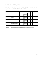
Microcomputer Components
Technical Support Group Munich
HL MC AT 1
Errata Sheet
January 14, 1997 / Release 1.0
Device :
Stepping Code / Marking :
SAK-C167CR-4RM
ES-AA
The C167CR-4RM is the 32 Kbyte ROM version of the C167CR, including an onchip CAN module, 2 Kbyte XRAM module, and a PLL oscillator circuit.
This errata sheet describes the functional problems known in this step. Problem
classification and numbering is performed relative to modules, where the C167
AC-step is the reference. Since most problems of earlier steps have already been
fixed in this step of the C167CR, problem numbering is not necessarily
consecutive.
The C167CR-4RM devices are mounted in a 144-pin Plastic Metric Quad Flat
Pack (P-MQFP-144-1) package.
Note: devices which are marked as ES-AA are engineering samples which may
not be completely tested in all functional and electrical characteristics. They
should be used for functional evaluation only.
Changes from Errata Sheet Rel. 1.1 for C167CR-LM devices with stepping
code/marking BA to this Errata Sheet Rel. 1.0 for C167CR-4RM devices with
stepping code/marking ES-AA:
-
Problems ADC.8, CPU.8, CPU.9, CPU.11, RST.1, X10 fixed
Start of Standard Conversion at end of Injected Conversion (ADC.10)
PLL Unlock Behaviour (PLL.1)
Deviations from DC/AC Specification
Errata Sheet C167CR-4RM, ES-AA, 1.0
-1/6-
Functional Problems
The following malfunctions are known in this step:
ADC.10:
Start of Standard Conversion at End of Injected Conversion
When an A/D conversion in any of the standard modes (single channel, auto
scan, continuous modes) is started by software within a time window of 2 TCL
(50 ns @ 20 MHz) before the end of an injected conversion, the following
problem will occur:
- the result of the injected conversion is not transferred to ADDAT2, and
interrupt request flag ADEIR is not set
- no further requests for injected conversions are processed
- the standard conversion is not started (i.e. the A/D converter is blocked)
Workaround:
Do not start a standard conversion while an injected conversion is in progress. In
this case, start the standard conversion in the ADEINT interrupt service routine
which is invoked after the injected conversion is finished. As an indication
whether an injected conversion is in progress, bits ADCRQ or ADST may be
tested.
- Main Program:
...
ATOMIC #4
; see Note 2)
BMOV
ADStart, ADCRQ ; copy current status of ADCRQ
JB
ADStart, Done
; injected conversion in progress ?
BSET
ADST
; no: start standard conversion here
BMOV
ADCRQ, CC31IR ; see Note 1)
Done:
...
; yes: start standard conversion in ADEINT ISR
- ADEINT Interrupt Service Routine:
...
BMOV
ADST, ADStart
BCLR
ADStart
...
RETI
Note 1): ATOMIC #4 should be used here to ensure correct flag handling and
avoid side effects which may be caused by interrupts
Note 2): In case ADCRQ has been set by a channel injection request from CC31
in the time between the second half of the decode phase and the second half of
the execute phase of instruction BSET ADST, flag ADCRQ may be
unintentionally cleared due to missing hardware bit protection of bit ADCRQ. This
does not effect the actual start and processing of an injected conversion, since an
internal (not user accessible) latch controls its correct operation. In case ADCRQ
is polled by other routines to check whether an injected conversion is in progress,
its state may be restored from flag CC31IR which is set simultaneously with
ADCRQ upon each channel injection request from CC31. In this case, it is
required that the ADEINT interrupt service routine properly clears flag CC31IR, or
that CC31 interrupt requests are serviced by an own service routine or PEC.
Compatibility with previous steps of the C167CR
Errata Sheet C167CR-4RM, ES-AA, 1.0
-2/6-
In previous steps (e.g. C167CR-LM AB-step), an injected conversion in progress
was aborted when a standard conversion was started by software (see C167
User's Manual V1.0 or V2.0, p. 16-8, third Note). If this effect was not desired, it
was suggested to check whether no injected conversion was in progress before
starting a standard conversion. This means that all systems which have
considered this proposal implicitly already have implemented the workaround
described above and will work without problems also with the C167CR-4RM
AA-step.
In the C167CR-4RM AA-step, as a correction of problem ADC.7 (Channel
Injection request coincident with start of standard conversion), start of standard
conversions will no longer abort injected conversions. If this 'new' feature is used,
the above software workaround must be used.
If the abortion of an injected conversion by the start of a standard conversion was
tolerated in sytems with previous steps (e.g. C167CR-LM AB-step), the
workaround must be implemented when switching to the C167CR-4RM AA-step.
PLL.1:
PLL Unlock Behaviour
When PLL operation has been selected during reset (P0H.7 = high), and the
input clock at XTAL1 fails or becomes unstable, the PLL can not properly
synchronize (lock) to the input clock, i.e. it is unlocked. In this situation, the
following problems will occur:
1. the PLL output clock may not stay at the PLL basic frequency, but may vary
between the basic and the maximum PLL frequency, depending on the transitions
of the input clock at pin XTAL1.
2. when the PLL unlock condition occurs in particular during reset, it is not
guaranteed that the PLL Unlock Interrupt Request Flag (XP3IR) is set to '1'.
When the unlock condition occurs while the controller is not in the reset state, the
PLL Unlock Interrupt Request Flag (XP3IR) will be correctly set to '1'.
Note: when the direct drive option has been selected during reset (P0H.7 = low),
and the input clock at XTAL1 fails or becomes unstable, the Oscillator Watchdog
(if enabled) will supply the internal CPU clock with the PLL basic frequency.
Functional
Problem
PLL.1
ADC.10
Short Description
Remarks
PLL Unlock Behaviour
Start of Standard Conversion at end of Injected
Conversion
Table 1:
Functional Problems of the C167CR-4RM
Specific Problems with X-Peripherals (XPERs)
Errata Sheet C167CR-4RM, ES-AA, 1.0
-3/6-
The following problems with the interface to XPERs, the CAN module, and the
XRAM module are currently known:
X9:
Read Access to XPERs in Visible Mode
The data of a read access to an XBUS-Peripheral (XRAM, CAN) in Visible Mode
is not driven to the external bus. PORT0 is tristated during such read accesses.
Functional
Problem
X9
1)
Short Description
fixed in
Step 1)
Read Access to XPERs in Visible Mode
refers to all devices with this stepping code (including engineering samples)
Table 2:
Functional Problems with XPERs on the C167CR-4RM
Errata Sheet C167CR-4RM, ES-AA, 1.0
-4/6-
Deviations from DC/AC Specification
The following table lists the deviations of the DC/AC characteristics from the
specification in the C167CR-4RM Data Sheet 12.96.
Problem
Parameter
Symbol
Limit Values Unit Test
min.
short name
max.
DCAH.1
ALE active current
IALEH
1000
instead of
500
-
µA
Condition
VOUT = 2.4 V
DCRL.1
RD#/WR# active
current
IRWL
-600
instead of
-500
-
µA
VOUT = VOLmax
DCP6L.1
Port 6 active current
IP6L
-600
instead of
-500
-
µA
VOUT = VOLmax
DCHYS.1
Input Hysteresis
(Special Threshold)
HYS
300
instead of
400
-
mV -
Table 3:
Deviations from DC/AC Specification of the C167CR-4RM
Errata Sheet C167CR-4RM, ES-AA, 1.0
-5/6-
In addition to the description in the C167 Derivatives User's Manual V2.0, the
following feature enhancements have been implemented in the C167CR-4RM:
Incremental position sensor interface
For each of the timers T2, T3, T4 of the GPT1 unit, an additional operating mode
has been implemented which allows to interface to incremental position sensors
(A, B, Top0). This mode is selected for a timer Tx via TxM = 110b in register
TxCON, x = (2, 3, 4). Optionally, the contents of T5 may be captured into register
CAPREL upon an event on T3. This feature is selected via bit QCAP = 1 in
register T5CON.10
Compatibility with previous versions:
In previous versions (e.g. C167CR-LM), both of the settings (TxM = 110b,
T5CON.10 = 1) were reserved and should not be used. Therefore, systems
designed for previous versions will also work without problems with the
C167CR-4RM.
Oscillator Watchdog
The C167CR-4RM provides an Oscillator Watchdog (OWD) which monitors the
clock at XTAL1 in direct drive mode. In case of clock failure, the PLL Unlock/OWD
Interrupt Request Flag (XP3IR) is set and the internal CPU clock is supplied with
the PLL basic frequency. This feature can be disabled by a low level on pin
Vpp/OWE. See also C167CR-4RM Data Sheet 12.96.
Bidirectional Reset
The C167CR-4RM allows to indicate an internal watchdog timer or software reset
on the RSTIN# pin which will be driven low for the duration of the internal reset
sequence. This option is selectable by software via bit BDRSTEN/SYSCON.3.
After reset, the bidirectional reset option is disabled (BDRSTEN/SYSCON.3 = 0).
See also C167CR-4RM Data Sheet 12.96.
Please note also the following functional difference to the C167CR-LM BA-step:
XBUS Peripheral Enable Bit XPEN/SYSCON.2
In the C167CR-4RM, bit SYSCON.2 is a general XBUS Peripheral Enable bit, i.e.
it controls both the XRAM and the CAN module.
Compatibility with previous versions:
When bit SYSCON.2 = 0 (default after reset) in the C167CR-4RM, and an access
to an address in the range EF00h ... EFFFh is made, either an external bus
access is performed (if an external bus is enabled), or the Illegal Bus Trap is
entered. In previous versions (e.g. C167CR-LM), the CAN module was accessed
in this case.
Systems where bit SYSCON.2 was set to '1' before an access to the CAN module
in the address range EF00h ... EFFFh was made will also work without problems
with the C167CR-4RM.
Errata Sheet C167CR-4RM, ES-AA, 1.0
-6/6-