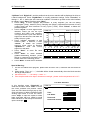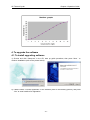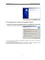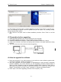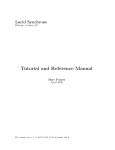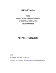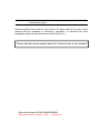
1
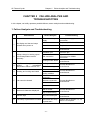
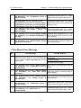
Note: The Bioer Co. reserves the right to modify this manual at any time without notice. Patent materials are included in this manual. All rights reserved. Any part of this manual shall be forbidden to photocopy, reproduce, or translate into other languages, without written permission from the Bioer Co. Please read this manual carefully before the Thermal Cycler is first operated! Document Number: BYQ60210000000BSM Document Version: August , 2009 Version 2.9 XP Thermal Cycler Important Note Important Note 1 CONVENTIONS Note: Because there is important information in this item, please read it carefully. Failure to follow the advice here will possibly result in damage or malfunctioning of the Thermal Cycler. Warning! This symbol means that you should be cautious to take an operation/procedure. Failure to follow the requirements in this item will possibly result in personal injury. 2 SAFETY During the operation, maintenance, or repair of the XP Thermal Cycler, the following safety measures should be taken. Otherwise, the guard provided by the Thermal Cycler is likely to be damaged, while the rated safety level to be reduced, and the rated operation conditions to be affected. The Bioer Co. shall not be in any way responsible for the consequences resulted from operators not following the requirements. Note: The Thermal Cycler, complying with the National Standard EN61010-2-010 & EN61326-1, is a general instrument of classⅠ, the protection degree is IP20. It applies to indoor and below an elevation of 2000 meters. a) Grounding Considerations A.C. power’s grounding should be grounded reliably for fear of an electric shock. The 3-pin plug with the Thermal Cycler’s power line is a safety device that should be matched with a grounded socket. Never let the third ground pin floating. If the 3-pin plug cannot be inserted, it is recommended to ask an electrician to install an appropriate power socket. b) Keep Away from Electric Circuits The operator is not allowed to open the Thermal Cycler. To changing components or adjust certain parameters inside the device must only be accomplished by the certificated professional maintenance personnel. Do not change elements while the power is still on. c) A.C. Power Considerations Before turn on the power, always check if the mains voltage is within the required A.C. 220-240V and whether the current rating of the power socket meet the required specification, i.e. 800W MAX. —i— XP Thermal Cycler Important Note d) A.C. Power Line Considerations As an accessory of the Thermal Cycler, the A.C. power line used should be a default one. If it is damaged, the A.C. power line may not be repaired, but could be replaced by a new one with same model and specification. The power line should be free of heavy objects during the Thermal Cycler’s operation. Keep the power line away from the place where people gather regularly. e) Connect the A.C. Power Line While connect or disconnect the power line, you should hold the 3-pin plug with your hand. Insert the plug thoroughly to ensure good contact between the plug and socket. Pull the plug, but not the line, when you need to disconnect to the mains. f) Requested Environments The Thermal Cycler should be placed in a low-humidity, dust-free, and good-ventilation room without caustic gas or powerful magnetic interference. In addition, water sources, such as pools and water pipes, should be kept a distance from the Thermal Cycler. Never cover or obstruct the openings of the Thermal Cycler, which are designed for ventilation and prevent the device’s interior from being too hot. When a single device is running, the shortest distance between its openings and the nearest object is 50cm; when two or more devices are running at the same time, the shortest distance is 100 cm. Do not place the device on a soft surface, for that will result in adverse ventilation near the device’s bottom openings. Too high temperature will lead to degraded performance or failure of the Thermal Cycler. Therefore, the device should be protected against any kind of heat sources like sunlight, ovens, or central heating equipment. If the Thermal Cycler is set aside for a long time, it is recommended to disconnect the power line to mains and cover the device with a piece of soft cloth or plastic to prevent dust from entering. Note: Once one of the following events occurs, you are suggested to disconnect the power line with mains, and contact the distributor or ask a certificated maintenance personnel for help. Liquid into the device; The device sprinkled or drenched; The device malfunctioning, giving off abnormal sound or odor; The device falling onto the floor or its shell damaged; Significant changes in the device’s performance. 3 EMC Consideration Note: This is a class A equipment, only suitable for use in establishments other than domestic, and those directly connected to a low voltage power supply network which supplies buildings used for domestic purpose. — ii — XP Thermal Cycler Important Note 4 Protection Degree: IP 20 5 LABELS a)Tablet Name: Base for XP Thermal Cycler Base: TC-XP Power: 220V-240VAC 800WMAX,50-60Hz Fuse: 5A Φ5×20mm Sort: classⅠ, IP20 SN: *******-*** Date:****.** Made in China Name:XP Thermal Cycler Model:TC-XP-* Block:XP-* SN:BYQ*******-*** Date:****.** Made in China BIOER TECHNOLOGY CO.,LTD. b)Warning Sign Warning! There are two warning signs read ‘HOT SURFACE!’ During the program execution and in the short period after the program execution, the metal part near those signs (on the block and hotlid) is not allowed to be touched by any part of the body for fear of the body burn! 6 MAINTENANCE The conical holes over the block should be cleaned regularly with soaked cotton swab in order to ensure sufficient contact and thus good heat conduction between each conical hole and the tube inside it. In case it is smeared, the surface of the Thermal Cycler can be scrubbed with a piece of dehydrated soft wet cloth. — iii — XP Thermal Cycler Important Note When cleaning, the instrument should be off. Corrosive scour is not allowed to clean the surface of the instrument. Warning! 7 WARRANTY AND SERVICE INFORMATION a)Warranty The Thermal Cycler is warranted for a period of one month, from the date of shipment from the company, to be free from defects in material and workmanship. The Bioer Co. shall be obligated, under this warranty, to exchange the XP Thermal Cycler that proves to be defective as described herein. XP Thermal Cycler is also warranted for a period of twelve months, from date of shipment from the company, to be free repaired for defects in material and workmanship. The Bioer Co.’s obligation under this warranty shall be limited to repair or exchange (at the Bioer Co.’s option) of XP Thermal Cycler that proves to be defective as described herein. The buyer is responsible for deliver to the maintenance shop designated by the Bioer Co. on all warranty claims. The buyer is also responsible for the transportation expenses of the freight to the maintenance shop. The Bioer Co. shall be responsible for the transportation expenses of the freight to the buyer (which is only applicable to domestic buyers). After the warranty comes due, the Bioer Co. reserves the right to charge cost price for maintenance of a defective device. b)Warranty Terms The above warranty is not applicable to defective devices with incorrect use, abnormal operating conditions, improper application, and unauthorized maintenance or alteration. The Bioer Co. makes no express warranties other than those that are described herein. Any descriptions in sales promotion under specific conditions shall not create an express warranty that the goods shall conform to such description. c) After-sell services hotline:+86-571-87774558 Note: Once it is opened, the package should be checked according to the packing list. If the buyer finds any items to be missing or damaged, do not hesitate to contact the distributor. After the acceptance check is passed, the buyer should fill out the check form and send its photocopy (or fax it) to the distributor. The Bioer Co. establishes the archives and maintenance records with the returned form. Please store the package and packing materials in a safe place in case of future device maintenance. The above warranty does not extend to goods damaged as the result of cheesy package. — iv — XP Thermal Cycler Content CONTENT CHAPTER 1 INTRODUCTION..................................................................................................................1 1. Brief Introduction of PCR Technique...................................................................................................1 2. PCR Applications....................................................................................................................................1 3. Features...................................................................................................................................................2 4. Operation................................................................................................................................................. 2 CHAPTER 2 SPECIFICATIONS............................................................................................................... 5 1. Normal Working Conditions..................................................................................................................5 2. Transportation and Storage Conditions..............................................................................................5 3. Basic Parameters...................................................................................................................................5 4. Performance............................................................................................................................................6 5. Software Functions................................................................................................................................ 6 CHAPTER 3 PREPARATIONS..................................................................................................................7 1. Structure Description............................................................................................................................. 7 2. Keyboard Diagram................................................................................................................................. 8 3. Introduction of pressing keys............................................................................................................... 8 4. Installation of Block Unit........................................................................................................................9 4.1 Installation......................................................................................................................................... 9 4.2 Dismantlement............................................................................................................................... 10 5. Inspection before Power-on............................................................................................................... 10 6. Power-on Procedures..........................................................................................................................11 CHAPTER 4 OPERATION GUIDE......................................................................................................... 12 1. How to run a single-block PCR program......................................................................................... 13 1.1 How to edit a PCR program.........................................................................................................14 1.2 How to set system parameters....................................................................................................18 2. How to run a double- block PCR program.......................................................................................20 2.1 How to edit a PCR program.........................................................................................................21 2.2 How to set system parameters....................................................................................................24 3. How to run a gradient block PCR program......................................................................................25 3.1 How to edit a PCR program.........................................................................................................26 3.2 How to set system parameters....................................................................................................29 3.3 Characteristics of temperature distributing of gradient block.................................................30 4. To upgrade the software..................................................................................................................... 30 4.1 To install upgrading software....................................................................................................... 30 —1— XP Thermal Cycler Content 4.2 To modify, repair or remove the upgraded software................................................................ 32 4.3 Preparation before upgrading...................................................................................................33 4.4 How to upgrade the software.......................................................................................................33 CHAPTER 5 FAILURE ANALYSIS AND TROUBLESHOOTING...................................................... 36 1. Failure Analysis and Troubleshooting...............................................................................................36 2. Single blocks Error message............................................................................................................. 37 3. Dual Blocks Error Message................................................................................................................38 APPENDIX 1 Connection Diagram.................................................................................................... 40 APPENDIX 2 Parameter Value & Meaning.......................................................................................41 —2— XP Thermal Cycler Chapter 1 CHAPTER 1 Introduction INTRODUCTION This chapter briefly introduces PCR technique and its applications, PCR thermal cyclers, and the characteristics of XP Thermal Cycler. 1. Brief Introduction of PCR Technique PCR (Polymerase Chain Reaction), or cell-free molecule cloning, is a technique for amplifying nucleic acids in vitro, emulating natural DNA replication process. The PCR technique, using two DNA strands to be amplified as template, and a pair of synthetic oligonucleotides as primers, rapidly reproduces the specific DNA pieces under the catalysis of a thermostable DNA polymerase. Because of its simplicity, rapidity, specificity, and sensitivity, PCR has been widely applied to all fields of life sciences since its invention by Mullis in 1983 and the discovery of the thermostable DNA polymerase by Erlich in 1989. Great achievements have been obtained in PCR’s applications in such areas as cytology, virology, oncology, genetics, forensics, and immunology. PCR technology is a milestone in the history of modern molecular biology. 2. PCR Applications Research Areas Gene cloning, DNA sequencing, mutation analysis, gene recombination and mutagenesis, identification and adjustment of DNA sequence of protein structure, detection of gene extension, construction of synthetic genes, construction of cloning and expression carrier, detection of polymorphism of a gene’s inscribed enzyme; Clinical Diagnoses Bacteria (spirochaeta, rickettsia, diphtheria bacillus, colon bacillus, dysentery bacillus, and clostridium); Virus (HTLV, HIV, HBV, HCV, HPVS, EV, CMV, EBV, HSV, measles virus, rotiform virus, B19 virus, and Lhasa virus); Parasite (malaria); Human hereditary diseases (Lesh-Nyhan syndrome, hemophilia, BMD, and DMD); Immunology HLA locus typing, qualitative analysis of T-cell receptor or antibody diversification, immune body gene mapping, quantitative analysis of lymph genes; Human Genome Identification of DNA markers using discrete repetitive; Project Sequence, construction of a genetic linkage map (detection of DNA, polymorphism, or semen mapping); Construction of a physical map, sequencing, and map expression; Specimen analysis in the venue, and HLA-DQα locus typing; Forensics Oncology Social and Colony Biology Pancreas cancer, rectum cancer, lung cancer, thyroid gland cancer, melanin cancer, and leukemia; Genetic species research, evolution research, animal protection research, ecology, environmental sciences, and experimental genetics; Paleontology Specimen analysis in archeology and museum; Biology Diagnosis of animal hereditary diseases and detection of plant pathogeny. —1— XP Thermal Cycler Chapter 1 Introduction 3. Features TC-XP Thermal Cycler is a PCR detection system with multiple functions. It has features and characteristics as followings: Provide eight kinds of interchangeable block units to meet various PCR experiments’ requirements; Adopting American ITI advanced thermoelectric cooling technology and thermoelectric cooling components manufactured under Japanese quality controlling mode, TC-XP thermal cycler possess the stable and reliable performance; With speedy temperature ramping rate at the maximum of 4℃/S, TC-XP can adjust ramping rate according to different experimental requirements; With multiple temperature-control modes, the instrument has much stronger compatibility; The central processor of TC-XP Thermal Cycler can automatically distinguish block units, as well as run other relevant programs; With colourful extra large screen LCD and human-oriented operating interface, its operation becomes simple and clear It has the function of auto power off protection, and continues to complete the unfinished program after the power supply is resumed; Height and pressure of hot lid is adjustable so as to fit different reacting tubes on the basis of practical operating situations, in order to prevent reagents from the evaporation and pollution; RS232 standard interface can be connected with normal computers, so as to realize the data printout of cycling process and result, and be convenient for analysis and research. 4. Operation Adopting many advanced techniques, XP Thermal Cycler block can meet different PCR experiments’ requirements. It holds a leading position in the field of similar products. XP Thermal Cycler Adaptation Carrier: TC-XP-A: 96×0.2ml TC-XP-C: 48×0.2ml+48×0.2ml TC-XP-G: 96×0.2ml(gradient) Standard Centrifuge Tube 0.2ml -2- XP Thermal Cycler Chapter 1 Introduction TC-XP-B: 60×0.5ml TC-XP-D: 30×0.5ml+30×0.5ml Standard Centrifuge Tube 0.5ml + Standard Centrifuge Tube 0.2ml + TC-XP-E: 48×0.2ml+30×0.5ml TC-XP-F: 384 wells plate TC-XP-H: 4 pieces of In Situ plate Standard Centrifuge Tube 0.5ml 384 wells plate In Situ plate -3- XP Thermal Cycler Chapter 2 CHAPTER 2 Specifications SPECIFICATIONS This chapter describes the Thermal Cycler’s operation, transportation and storage conditions, basic parameters, performance and functions. 1. Normal Working Conditions Ambient temperature: 10℃30℃ Relative humidity: Power supply: Note: ≤70% 220-240VAC,800W MAX,50-60Hz Before power-on, please check whether the above working conditions are satisfied. Pay special attention to the power line’s reliable grounding. 2. Transportation and Storage Conditions Ambient temperature: -20℃-+55℃ Relative humidity: ≤80% 3. Basic Parameters Model Model of Main Unit Model of Block Unit Test-tube Volume TC-XP-A TC-XP-B TC-XP-C TC-XP-D TC-XP-E TC-XP-F TC-XP-G TC-XP-H XP-H TC-XP XP-A XP-B XP-C XP-D XP-E XP-F XP-G 96×0.2ml 60×0.5ml Centrifu ge tube 48×0.2ml 48×0.2ml Centrifu ge tube Centrifu ge tube 30×0.5ml 48×0.2ml Centrifuge tube 384 Wells plate 96×0.2ml Centrifu ge tube 30×0.5ml 30×0.5ml Temperature Range Centrifu ge tube 4pieces in situ plate 4C 99C Heating Rate ≥4.0C ≥3.0C ≥4.0C ≥1.8C Cooling Rate ≥3.0C ≥1.8C ≥3.0C ≥1.8C Temperature uniformity Temperature Control Accuracy Maximum Gradient ≤0.4C ≤0.6C ≤0.5C ≤0.5C ≤0.5C ≤0.5C ≤0.4C ≤0.4C ≤0.3C ≤0.3C ≤0.4C ≤0.4C ≤0.4C ≤0.3C ≤0.4C ≤0.3C ╱ ╱ ╱ ╱ ╱ ╱ 30C ╱ -4- XP Thermal Cycler Minimum Gradient Temperature set value of hot-lid ╱ Chapter 2 ╱ ╱ ╱ ╱ ╱ 1C 30C 110C Size(mm) 470mm×340mm×260mm(L×W×H) Weight(kg) 10 kg Fuse 250V Computer Interface Note: Specifications ╱ ╱ 5A Ф5×20 RS232 When temperature set value of hot-lid is lower than that of block, the temperature of hot-lid showed in the display would be higher than the set value. 4. Performance Maximum number of cycles:99 Maximum procedures within a cycle:16 Number of programs:99 Noise:59dB (Background Noise: below 40dB,testing on 1m dead ahead) 5. Software Functions File editing and saving File accessing, modifying and deleting Adjusting the heating/cooling rate automatically Automatic temperature &time increments/decrements during cycling program execution Displaying the data at each phase of program execution instantly Pause of program running Stop of program running Auto-restart in case of power failure Soft upgrading via RS232 interface Sound alarm Estimating total program execution time and remaining program running time Date and time (year, month, day, hour, minute, second) display and calibration Failure protection and alarming Note: The above software functions are for reference only. The Bioer Co. reserves the right to modify the software functions without notice. -5- XP Thermal Cycler Chapter 3 CHAPTER 3 Preparations PREPARATIONS This chapter introduces the XP Thermal Cycler’s mechanical structure, the keyboard and each button’s functions, and some preparations before power-on. Before any operation, please read this chapter carefully and make sure you are familiar with the steps introduced. 1. Structure Description 1 2 3 4 5 6 7 8 Block LCD Screen Operating Keyboard Ventilating Hole Power Switch Power Supply Fuse Socket RS232 Interface The fuse specifications are as follows: 250V 5A, Φ5×20mm. The fuse should be Notes: replaced by one that meets those specifications. If you need certificated fuses, please contact the distributor or manufacturer. -6- XP Thermal Cycler Chapter 3 Preparations 2. Keyboard Diagram 2 3 ABC DEF 1 4 5 6 GHI JKL MNO 7 8 9 PQRS TUV WXYZ Shift 0 +/- A B Enter 1 1 2 3 ABC DEF J K3L 4 1 54 27 65C APQRS B 38 6FV DTEU GHI JGK H LI MJNKOL TPQRS UV JAK L B WXYZ TUV ABC 4 87I GH 7 PQRS Shift A 7 0 Shift PQRS B A B Shift A 2I GH DAEBFC 5 Shift Enter 8 T+/U0 V 9 WXYZ +/- 0 Enter +/- Enter 2 34 5 6 DGEHFI JKL MNO 2 3 4 5 67 8 ABC DEF GHI JKL M NO PQRS TUV 0 49 5 6 7 8 9 Shift GWXYZ HI JKL MNO PQRS TUV A B WXYZ 8 9 Shift 0 0 +/- MNO 98 Enter MNO DEF 60 M N9O B 16 5 4 3 21 1 7 +/PQRS WXYZ Shift A B 3 DEF ABC 1 3. Introduction of pressing keys 2 ABC “Digit & Letter”, select 9 the letter by pressing in succession. +/- WXYZ +/- “Shift”,shift A B one block to another and Capital letters to small TUV WXYZ from Enter “Function” , change “+, -” when editing process temperature and modifying time Enter “Right/Left”,moving the cursor one position to the left or right when Enter pressing during file parameter setting. “Up/Down”,moving the cursor one position to the up or down when pressing during file parameter setting. “Enter”,press it to accept the present parameters setting displayed on the screen when setting documents. “Menu”, displaying the main menu when pressing during file editing or hot lid temperature rising process. -7- XP Thermal Cycler Chapter 3 Preparations 4. Installation of Block Unit The main unit must link with the block unit so as to work normally. Please install or dismantle the block unit according to the following steps: 4.1 Installation a) Before installing block, please take down the rubber protection strip, which can protect the bit from distortion during transportation, from radiator. b) Put the block onto the block bath and push it slowly until reliable connection between block’s socket and Main Unit Connecting Plug achieved, thus to close the fixed blots. c) To close the fixed bolt and tighten its screws; d) To install the back air-dispelling block. 1 2 3 5 4 b a b a b c d c 6 7 Main Unit (the base: TC-XP) Main Unit Connecting Plug Release key Fixed Bolt Screw 8 Block Bath Block Fixed Bolt Back Air-dispelling Block -8- XP Thermal Cycler Note: Chapter 3 Preparations Make sure to switch off the power supply before installing block. When install block, please pay close attention to push the block slowly; otherwise, the main unit co damaged. When uninstall block, please draw the block from the block bath gently. It’s forbidden to lean the blo connection wire. After installation, the block unit will be recognised by the main body automatically, and will be ready other operation. 4.2 Dismantlement a) Take down the back air-dispelling block; b) Unscrew screws of the fixed bolt and unbolt it; c) Please draw the block from the block bath gently. (During uninstall of block, please pay close attention to protect the main unit from moving with the block.) d) Take out the block. The dismantlement is finished. c d c c b a b 5. Inspection before Power-on Before switch the power on, please ensure that: 1) Supply voltage falls within the specified limits (refer to Chapter 2); 2) The plug has been inserted into the power socket reliably; 3) The grounding of the power line is reliable. -9- XP Thermal Cycler Chapter 3 Preparations 6. Power-on Procedures Turn on the power (i.e. turn the power switch to position “–“), the XP Thermal Cycler will beep twice, and the LCD will display “Self testing ”. That means the device is under self-testing, which will last for about 1-2 minutes. Please wait patiently. After the self-testing, the main menu will be displayed, and the device is ready for operations such as editing, accessing, modifying, or deleting a PCR amplification file. - 10 - XP Thermal Cycler Chapter 4 Operation Guide CHAPTER 4 OPERATION GUIDE There are eight kinds of block units suitable to XP Thermal Cycler. In this chapter, we will explain in details on operations of every kind of block unit, for example, how to edit, access, modify, delete, or run a PCR amplification file, how to set parameters under different block unit. Warning! Please turn off the power immediately and contact the distributor if abnormal sound or display appears after power-on, or if failure alarm and display are found in the process of the device’s self-testing. Note: If the number of samples is less than the number of conical holes of the block, the sample tubes should be evenly distributed over the block, in order to ensure that the heated lid will stably press on the top of the sample tubes, so that both the block’s load and the temperature distribution in each tube are even. Note: Before closing the cover, please revolve the knob counter-clockwise according to the knob diagram till there sound "dang, dang....." Please note that the knob can be tightened by revolving clockwise, but can be loosed by revolving counter-clockwise. After closing the cover but before power on, please revolve the knob clockwise till it sound "dang,dang....." Revolve the knob one more turn. At the beginning of revolving the knob clockwise or counter-clockwise, you can hear "dang,dang...." sound,press the release key by your finger; meanwhile, revolve the knob counter-clockwise for two turns, thus to loose the release key to revolve the knob. Are you ready? Let’s begin! TC-XP-A Single-block Program TC-XP-B Single-block Program TC-XP-E Dual-block Program TC-XP-F Single-block Program - 11 - TC-XP-C Dual-block Program TC-XP-G Gradient Block Program TC-XP-D Dual-block Program TC-XP-H Single-block Program XP Thermal Cycler Chapter 4 Operation Guide 1. How to run a single-block PCR program Switch the power on, XP Thermal Cycler will beep twice, and it shows the power supply is connected well. The screen will display “Self-testing ”,and the instrument will carry on self testing. The self-testing needs about 1~ 2 minutes and please wait patiently. If the self-testing is successful, the screen will display the main interface. Main Interface On the left top of the main interface it displays the state of Hot lid. On the central area it displays Bioer Co. information, software version number, block model, default file, default user, control mode and sample volume. Press “File” to enter file list interface; Press “System” to enter system parameter setting interface; If the default file has no password, press “Run” to enter running mode or enter the interface displaying sample volume input window. If the default file has password, press “Run”, thus a dialog box will be showed to indicate the user to input the password. Enter password: - Press digtal button to enter password directly. Then, press “Back” to go back the main interface, press “Accept” to confirm the password, thus to enter file running interface or sample volume input window. If the password is wrong, there will be displayed a dialog box as below: Hotlid=off BIOER Bioer Technology Co.,Ltd Version: 2004-1.2 Block: **×** Default User: BIOER Default File: PCR1 Control Mode: Tube File System Hotlid=off Run 2004-11-1 10:05:00 BIOER Bioer Technology Co.,Ltd Version: 2004-1.2 Block: **×** Default User: BIOER Default File: PCR1 Control Mode: Tube Password error. Try again. - 2004-11-1 10:05:00 If the current Control Mode is Block mode, press “Accept” button to enter file running interface. If the current Control Mode is Tube mode, press “Accept” button, thus there will be displayed a dialog box to indicate the user to input the sample volume. Please enter sample volume: 020μl - 12 - Enter password: Back Accept XP Thermal Cycler Press Character button to input sample volume according to practical condition. Under Tube mode, the overshooting temperature and keeping time will be dirrerent in the case of different sample volume. Press “Back” to go back the main interface. Press “Run” to enther file running interface. Chapter 4 Operation Guide Hotlid=off 2004-11-1 10:05:00 BIOER Bioer Technology Co.,Ltd Version: 2004-1.2 Block: **×** Default User: BIOER Default File: PCR1 Control Mode: Tube Please enter sample volume: 020μl Back Run 1.1 How to edit a PCR program Press “File” on the main interface to enter file list interface. There are 3 files listed in the form as showed in the picture. When the flashing bar is flashing in the User Column, select users through pop-up key; at this time, the File Name Column will display the relative files of the selected user dynamically. Shift to the File Name Column, where the flashing bar will flash, thenselect relative user’s file through pop-up key. File List Interface Press “Edit” to edit the file indicated by the cursor. Press “New File”to edit a new file. Press “Delete” and the system will alarm “Do you want to delete the file? Please select ‘F3’ or ‘F4’.”, then according to the alert to select(Delete) or (BACK). Hotlid=off No. User 1 BIOER1* 2 BIOER2 3 BIOER3 Edit - 13 - New File 2004-11-1 10:05:00 File Name Save Time PCR1 2004-11-1 PCR2* 2004-11-1 PCR3 2004-11-1 Delete Back Run XP Thermal Cycler If the file has no passpord, press“Edit” to enter file editing interface; While if the file has password, press “Edit”, thus a dialog will be displayed to indicate the user to enter the password. Chapter 4 Operation Guide Hotlid=off No. User 1 BIOER1* 2 BIOER2 3 BIOER3 2004-11-1 10:05:00 File Name Save Time PCR1 2004-11-1 PCR2* 2004-11-1 PCR3 2004-11-1 Enter password: - Press Character button in the main interface to input the password directly. Press “Back” to go back file list interface. Press “Accept” to confirm the password, and then the system will enter the file editing interface, Enter password: Back Accept If the file has no password, press “Run” to enter file running interface or sample volume input interface. If the file has password, press “Run”, a dialog box will be displayed for inputting the password. Press “Back” to go back the file list interface. Press “Accept” to confirm the password, and then the system will enter file running interface of sample volume input window. Press “Run” in the file list interface, and input the password: If the current Control Mode is Block mode, Press “Accept” to enter file running interface; while if the current Control Mode is Tube mode, press “Accept”, thus a dialog box will be displayed for inputting sample volume. Hotlid=off No. User 1 BIOER1* 2 BIOER2 3 BIOER3 2004-11-1 10:05:00 File Name Save Time PCR1 2004-11-1 PCR2* 2004-11-1 PCR3 2004-11-1 Please enter sample volume: 020μl Press Character button to input sample volume according to practical condition. Press “Back” to go back file list interface. Press “Run” to enter file running interface. Note: Please enter sample volume: 020μl Back Run The sign“*”at the top of User and File indicates the current running file is default one, which can be modified in the parameter setting interface. - 14 - XP Thermal Cycler Chapter 4 Operation Guide File Edit Interface In this interface, you can edit sections and Hotlid=off 2004-11-1 10:05:00 segments of the file. A file is comprised by 100 sections and segments. And the sections 75 contain many segments, which you can 50 set cyclers to be run (refer to the figure). 25 Move cursor by pressing “Up/Down” and 0 “Right/Left”, and the position that the Temp 1c 95.0 2c 55.0 3c 72.0 4 04.0 cursor reaches will be displayed in white Time 01:00 02:00 01:45 00:00 on a black background. Press “Digit & Seg. Temp(C) Time Ramp(C/s) +Temp +Time Letter” to modify parameter settings. 1c 95.0 01:00 #.# +0.0 +0:00 Press “Function” to change +/-, but +/2c 55.0 02:00 #.# +0.0 +0:00 before the zero cannot be modified. If it 3c 72.0 01:45 #.# +0.0 +0:00 needs to go back to the main interface on 4 04.0 00:00 #.# +0.0 +0:00 midway, press “Save” first then press Cycle1 ×10 From 01 to 03 “Main”. +Seg. +Cycle Delete Back Save Press “+Seg.” to enter segment edit interface. In every segment, you can set setting temperature (Temp.), duration (Time), Ramping rate (Ramp), temperature increment of every cycler(+Temp) and time increment of every cycler (+Time). Press “Delete” to delete the present segment. Press “+Cycle” to enter segment edit interface, where you can set cycle numbers and initial cycle segment. The figure shows a cycle from the first segment to the third one, and there are totally 10 times cycles. Press “+Cycle” repeatedly to add sections (max.: 5 sections ). Press “Delete” to delete the present segment. Move cursor by pressing “Up/Down” to enter the former segment or the latter. Press “Save” to enter file save interface. Press “Back” to go back to File List Interface. Special Warning: 1 For the new edited PCR program, please save first then run it, otherwise the file file can’t be run; 2 When setting “Time” as “--:--”, the hotlid will be closed automatically when the block reaches the target temperature. Segment 1 Seg. 1 section 1 Cycle1 ×** From ** to ** Segment 2 Seg. 2 section 2 Cycle2 ×** From ** to ** File · · · · · · section 5 Cycle5 ×** From ** to ** Relation of sections and segments in a file - 15 - Segment16 Seg. 16 XP Thermal Cycler Chapter 4 Operation Guide File Save Interface In this interface press “Digit&Letter” to Hotlid=off 2004-11-1 10:05:00 enter the file name. Press “enter” to move abc the cursor forwards one position. Select “User、File Name……” through pop-up key. Click left button to delete characters while User: BIOER clicking right button to move the cursor. Press “Main” to go back to the main File Name: PCR1 interface. Password: * Press “Caps key” to shift the capital or small letter, and there will be a Password confirm:* capital or small letter indication on the left top of the screen. (as the example: abc) Press “Save” to save the file. When the file is normally saved, the system Main Caps Save Run will remind “File have been saved. Please continue another operation”, Press “Enter” to cancel the reminding bar. If the file was used, the system will remind you to rename (Rename) or continue to save (Save). If the current Control Mode is Block mode, press “Run” to enter file running interface; if the current Control Mode is Tube mode, press “Run”, thus a dialog box for indicating to input sample volume will be displayed. Please enter sample volume: 050μl Press Character button to input sample volume according to practical condition. Press “Back” to go back file save interface. Press “Run” to enter file running interface. Enther the file save interface,if the user Hotlid=off 2004-11-1 10:05:00 press “Run” without pressing “Save”, the abc system will remind “The modifications will be lost after running. Do you still want to run?” User: BIOER Press “No” to go back file save interface. File Name: PCR1 Press “Yes” to enter file running Password: * interface and sample volume input interface. (Note: the modification here Password confirm:* cannot be saved after the program is running over.) The modifications will be lost after running. Press “Yes”, if the current Control Do you still want to run? Mode is Block mode, the program will No Yes enter file running interface; if the current Control Mode is Tube mode, the system will pop up a dialog box of sample volume input: Please enter sample volume: 050μl - 16 - XP Thermal Cycler Chapter 4 Operation Guide Press Character button to input sample volume according to practical condition. Press “Back” to go back file list interface. Press “Run” to enter file running interface. File running interface When the file is normally running, “” at Hotlid=off 2003-11-1 10:05:00 “Now Running” will continuously flash. 100 When running is over, the system will 75 remind “File running is over ,Press ‘Enter’ 50 back to the main interface”. 25 Press “Stop” and it will remind “Do you 0 want to stop running? Please select 4 04.0 Temp 1c 95.0 2c 55.0 3c 72.0 ‘F1’or ‘F3’.”. According to the 1:00 02:00 01:45 00:00 Time reminding information to select File Name:PCR1 “STOP” or “START”. User: BIOER Now Running Press “Pause” and it will remind 1c Temp=00.0 Time=00:00 Cycle1 01 of 10 “Pause state now. Press ‘F3’ to Total Time: 00h 56m Remainig Time:00h 56m continue running.” According to the reminding information you can select “START” to continue. Stop Pause Start Skip View File Press “View File” to view edited PCR programs. Press “Skip” to stop current temperature and run the next. 1.2 How to set system parameters System Parameter Setting Interface In the main interface press “System” to enter system parameter setting interface. Press “Enter” to move the cursor to next item. The option is followed by the symbol “ ”. Press “Up/Down”to roll the option for selecting, and other information can be entered by pressing “Digit&Letter”. Press “Right/Left” to move cursor’s position. Press “Back” to go back to the main menu. Press “Save” to save parameters. Hotlid=off 2003-11-1 10:05:00 Date(yy-mm-dd): 04-10-22 Time(hh-mm-ss): 14:53:19 Special Reminding: When set the parameter, please press the “Save”, otherwise the parameter remains the original one. Default User: Default File: PCR1 BIOER Control Mode: Hotlid Temp: Block Temp: Block OFF 30C Key Beep: Run End Beep: ON OFF Back Save 1.2.1 “Date”and“Time”stand for default time after power-on. 1.2.2 “Default File” and “Default User” stand for name and user of default running procedure after power-on. 1.2.3 “Control Mode” stands for default control model after power-on., including two optional modes , named “Block” and “Tube”. - 17 - XP Thermal Cycler Chapter 4 Operation Guide “Block” mode subjects to simple temperature control during the course of cooling & heating only. Compared to the block, cooling & heating rate of reagent is a little slower, therefore, the actual change of reagent’s temperature is different from the setting procedure. The actual time for reagent to reach & keep the setting temperature is far shorter than the setting time. (Please refer to the following figure: relation between block temperature and reagent temperature) Block Reagent “Tube mode” has considered the phenomenon that the cooling & heating rate is a little slower than that of block. There is an overshoot after reaching the setting temperature, which can allow reagent to reach the setting temperature faster. During the same setting time as “Block”, the actual time for reagent to keep the setting temperature is prolonged obviously. (Please refer to the following figure: relation between block temperature and reagent temperature) Block Reagent 1.2.4 “Hotlid Temp”: means hotlid’s state “on/off”, the target temperature of hotlid (can be input directly). 1.2.5 “Block Temp”: means the hotlid is heating, the costant temperature of block. This function is available only when the hotlid is under “on” state. 1.2.6 “Key Beep”, “Run End Beep” stand for the sound of pressing key and reminding sound after the procedure runs over respectively. See details in the APPENDIX 2. 1. After set the parameters, please press “Save” to confirm the setting, NOTE: otherwise the parameter remains the original one. 2. Before the instrument leaves the factory, its inside clock has been adjusted in accordance with Beijing Time. 3. For the first use of the instrument, you are advised to confirm whether the date and clock time are set right as local time. - 18 - XP Thermal Cycler Chapter 4 Operation Guide 2. How to run a double- block PCR program Switch the power on, XP Thermal Cycler will beep twice, and it shows the power supply is connected well. The screen will display “Self testing ”,and the instrument will carry on self testing. The self-testing needs about 1~2 minutes, and please wait patiently. If the self-testing is successful, the screen will display the main interface. Dual block means two blocks: Block A and B respectively represent actual block on the left and right. Press “Shift” to operate A or B blocks in the same interface. The following introduction takes the example of operating A block. In the top center of the main interface, it blinking displays the present operating block. As in the illustration it shows the control symbol is “A”. Press “Shift” to change control symbol. In the central area of the main interface it displays the types of A & B blocks, default file, default user, control mode and sample volume. Press “File” to enter file list interface. Press “System” to enter system parameter setting interface. Main Interface Bioer Version 2004-1.2 A 2004-11-1 10:05:00 A Block: **×**well Default User: BIOER Default File: PCR1 Control Mode: Block Self-testing B Block: **×**well Default User: BIOER Default File: PCR2 Control Mode: Block 0 File If the file has no password, press “Run” to enter file running interface or sample volume input interface. If the file has password, press “Run”, a dialog box will be displayed for inputting the password. Press “Back” to go back the file list interface. Press “Accept” to confirm the password, and then the system will enter file running interface of sample volume input window. Self-testing System Run Bioer Version 2004-1.2 A 2004-11-1 10:05:00 A Block: **×**well Default User: BIOER Default File: PCR1 Control Mode: Block Enter password: B Select Sample Volume: 050μl Press Character button to input sample volume according to practical condition. Press “Back” to go back file list interface. Press “Run” to enter file running interface. Block: **×**well Default User: BIOER Default File: PCR2 Control Mode: Block Back - 19 - Accept XP Thermal Cycler Chapter 4 Operation Guide 2.1 How to edit a PCR program In the main interface press “File” to enter file list interface There are 3 files listed in the form as showed in the picture. When the flashing bar is flashing in the User Column, select users through pop-up key; at this time, the File Name Column will display the relative files of the selected user dynamically. Shift to the File Name Column, where the flashing bar will flash, then select relative user’s file through pop-up key: If the file has no password, press “Edit” to enter file edit interface; if the file has password, press “Edit”, the system will poop up a dialog box for inputting password. File List Interface Bioer Version 2004-1.2 A 2004-11-1 10:05:00 A No. User File Name Save Time 1 BIOER1* PCR1 2004-11-1 2 BIOER2 PCR2* 2004-11-1 3 BIOER3 PCR3 2004-11-1 B Enter password: - Block: **×**well Default User: BIOER Default File: PCR2 Control Mode: Block Edit New File Delete Back Run Press Digital buttom to input password directly. Press “Back” to go back the file edit interface. Press “Accept” to confirm the password, and the system will enter file edit interface. If the password is wrong, the system will pop up a reminding dialog box. Press “New File” to edit a new file. Press “Delete” and the system will alarm “Do you want to delete the file? Please select ‘F3’ or ‘F4’.”, then according to the alert information to select (Delete) or (BACK). Press “Back” to go back to the main interface. If the current Control Mode is Block Bioer Version 2004-1.2 A 2004-11-1 10:05:00 Mode, press “Run” to enter into File A Running Interface; while if the current No. User File Name Save Time Control Mode is Tube Mode, press 1 BIOER1* PCR1 2004-11-1 “Run”, the system will pop up a dialog 2 BIOER2 PCR2* 2004-11-1 box for inputting password. 3 BIOER3 PCR3 2004-11-1 Enter password: - Enter password: - Press Digital button to input password directly. Press “Back” to go back file edit interface. Press “Accept” to confirm the password, the system will enter file running interface or sample volume input interface. If the password is wrong, the system will pop up a reminding dialog box. Note: B Block: **×**well Default User: BIOER Default File: PCR2 Control Mode: Block Back Accept The sign“*”at the top of User and File indicates the current running file is default one, which can be modified in the parameter setting interface. File Edit Interface - 20 - XP Thermal Cycler Chapter 4 Operation Guide In this interface move cursor by pressing Bioer Version 2004-1.2 A 2004-11-1 10:05:00 “Up/Down” and “ Right/Left ” , and the Seg. Temp(C) Time Ramp(C/s) +Temp +Time position that the cursor reaches will be 1c 95.0 01:00 #.# +0.0 +0:00 displayed in white on a black background. 2c 55.0 02:00 #.# +0.0 +0:00 Press Digit & Letter to modify parameter 3c 72.0 01:45 #.# +0.0 +0:00 settings. Press Function to change “+/-“, 4 04.0 00:00 #.# +0.0 +0:00 but “+/-“ before the zero cannot be modified. If it needs to go back to the main interface Cycle1:×10 From 01 to 03 on midway, press “Save” first then press B “Main”. Block: **×**well Press “+Seg.” to enter segment edit Default User: BIOER interface. In every segment, you can Default File: PCR2 set setting temperature (Temp.), Control Mode: Block duration (Time), Ramping rate (Ramp), temperature increment of every cycler (+Temp) and time increment of every +Seg. +Cycle Delete Back Save cycler (+Time). Press “Delete” to delete the present segment. Press “+Cycle” to enter segment edit interface, where you can set cycle numbers and initial cycle segment. The figure shows a cycle from the first segment to the third one, and there are totally 10 times cycles. Press “+Cycle” repeatedly to add sections (max.: 5 sections ). Press “Delete” to delete the present segment. Move cursor by pressing “Up/Down”to enter the former segment or the latter. Press “Save” to enter file save interface. Press “Back” to go back to File List Interface. Special Warning: 1 For the new edited PCR program, please save first then run it, otherwise the file File cannot be run. 2 When setting “Time” as “--:--”, the hotlid will be closed automatically when the block reaches the target temperature. File Save Interface In this interface press Digit & Letter to enter the file name. Press “Enter” to move the cursor forwards one position. Select “User、 File Name……” through pop-up key. Click left button to delete characters while clicking right button to move the cursor. Press “Main” to go back to the main interface. Press “Caps” to shift the capital or small letter, and there will be a capital or small letter indication on the left top of the screen. (As the example: abc) Press “Save” to save the file. When the file is normally saved, the system will remind “File have been saved. Please continue another operation” , A 2004-11-1 10:05:00 abc User : BIOER File Name: PCR1 Password: ** Password confirm:** Bioer Version 2004-1.2 B Block: **×**well Default User: BIOER Default File: PCR2 Control Mode: Block Main - 21 - Caps Save Run XP Thermal Cycler Chapter 4 Operation Guide Press enter key to cancel the reminding bar. If the file was used, the system will remind you to rename (Rename) or continue to save (Save). If the current Control Mode is Block Bioer Version 2004-1.2 A 2004-11-1 10:05:00 mode, press “Run” to enter the file abc running interface. If the current User : BIOER Control Mode is Tube mode, press File Name: PCR1 “Run”, thus the system will pop up a Password: dialog box as below: Please**enter sample volume: Password confirm:** 020μl Please enter sample volume: 020μl B Block: **×**well Default User: BIOER Default File: PCR2 Control Mode: Block Press Character button to input sample volume according to practical condition. Press “Back” to go back file list interface. Press “Run” to enter file running interface. Back Run Enter the file save interface. If press “Run” Bioer Version 2004-1.2 A 2004-11-1 10:05:00 directly without pressing “Save”, the abc system will remind: “The modifications will User : BIOER be lost after running. Do you still want to File Name: PCR1 run?” Password: ** Press “No” to go back file save The modifications will be lost after running. Password confirm:** interface. Do you still want to run? Press “Yes” to enter file running interface and sample volume input B interface. (Note: the modification Block: **×**well cannot be saved after the program is Default User: BIOER running over.) Default File: PCR2 Press “Yes”, the program will enter file Control Mode: Block running interface if the current Control Mode is Block mode; if the current No Yes Control Mode is Tube mode, the system will pop up a dialog box as below: Please enter sample volume: 050μl Press Character button to input sample volume according to practical condition. Press “Back” to go back file list interface. Press “Run” to enter file running interface. - 22 - XP Thermal Cycler Chapter 4 Operation Guide File Running Interface When the files’ running is over, the system will alarm “File running is over. Press ‘Enter’ back to the main interface.”. Press “Stop” and it will remind “Do you want to stop running? Please select ‘F1’ or ‘F3’.”.According to the reminding information to select “STOP” or “START”. Press “Pause” and it will remind “Pause state now. Press ‘F3’ to continue running.” According to the reminding information you can select “START” to continue. Press “View File” to view edited PCR programs. “Skip” to stop current Press temperature and run the next. Bioer Version 2004-1.2 Total Time:00h 00m B Remaining Time: 00h 00m Hotlid=042C Block: **×**well Default User: BIOER Default File: PCR2 Control Mode: Block Stop Pause Start Skip View File System Parameter Setting Interface Bioer Version 2004-1.2 Default User: Default File: A 2004-11-1 10:05:00 BIOER PCR1 Control Mode: Block Hotlid Temp: OFF Block Temp: 30C Date(yy-mm-dd): 04-11-01 Time(hh-mm-ss): 02:24:40 Key Beep: ON Run End Beep: ON B Block: **×**well Default User: BIOER Default File: PCR2 Control Mode: Block Special Reminding: When set the parameter, please press the “Save”, otherwise the parameter remains the original one. NOTE: 2004-11-1 10:05:00 User: BIOER Seg. 1 Temp(C) Time(m:s) Cycle1 PV 32.6 00:00 01 SV 95.0 01:00 01 2.2 How to set system parameters In the main interface press “System” to enter system parameter setting interface. Press Enter” to move the cursor to next item. The option is followed by the symbol “ ”. Press “Up/Down” to roll the option for selecting, and other information can be entered information by pressing “Digit&Letter”. Press “Right/Left” to move cursor’s position. Press “Back” to go back to the main menu. Press “Save” to save parameters. A File Name: PCR1 Back Save 1.After set the parameters, please press “Save” to confirm setting, otherwise the parameter remains the original one 2.Before the instrument leaves the factory, its inside clock has been adjusted in accordance with Beijing Time For the first use of the instrument, you are advised to confirm whether the date and clock time are set right as local time. - 23 - XP Thermal Cycler Chapter 4 Operation Guide 3. How to run a gradient block PCR program Switch the power on, XP Thermal Cycler will beep twice, and it shows the power supply is connected well. The screen will display “Self-testing ”,and the instrument will carry on self testing. The self-testing needs about 1~2 minutes, and please wait patiently. If the self-testing is successful, the screen will display the main interface. On the left top of the main interface it displays the state of Hotlid. On the central area it displays Bioer Co. information, software version number, block type, default file, default user, control mode and sample volume. Press “File” to enter file list interface Press “System” to enter system parameter setting interface If the current default file has no password, press “Run” to enter running mode and samle volume input interface. If the current default file has password, press “Run” , thus the system will pop up a dialog box for inputting password. Enter password: - Press Digital Button to input password directly. Press “Back” to go back the main interface. Press “Accept” to confirm the password, and the system will enter the file running interface or sample volume input interface. If the password is wrong, the system will pop up a dialog box as below: Hotlid=off 2004-11-1 10:05:00 BIOER Bioer Technology Co.,Ltd Version: 2004-1.2 Block: Grad Default User: BIOER Default File: PCR1 Control Mode: Block File Hotlid=off No. User 1 BIOER1 2 BIOER2* 3 BIOER3 System Run 2004-11-1 10:05:00 File Name Save Time PCR1 2004-11-1 PCR2* 2004-11-1 PCR3 2004-11-1 Password error. Try again. - Enter password: If the current Control Mode is Block mode, press “Accept” button to enter Back Accept file running interface. If the current Control Mode is Tube mode, press “Accept” button, thus there will be displayed a dialog box to indicate the user to input the sample volume. Please enter sample volume: 020μl Press Character button to input sample volume according to practical condition. Press“Back” to go back the main interface.Press “Run” to enther file running interface. - 24 - XP Thermal Cycler Chapter 4 Operation Guide 3.1 How to edit a PCR program File List Interface Press “File” on the main interface to enter file list There are 3 files listed in the form as Hotlid=off showed in the picture. When the flashing bar No. User is flashing in the User Column, select users 1 BIOER1 through pop-up key; at this time, the File 2 BIOER2* Name Column will display the relative files of 3 BIOER3 the selected user dynamically. Shift to the File Name Column, where the flashing bar will flash, then select relative user’s file through pop-up key. If the file has no password, press “Edit” to enter file edit interface.If the file has password, press “Edit”, the system will pop up a dialog box as below: interface, 2004-11-1 10:05:00 File Name Save Time PCR1 2004-11-1 PCR2* 2004-11-1 PCR3 2004-11-1 Enter password: - Edit New File Delete Back Run Press Digital Button to input password directly. Press “Back” to go back file edit interface. Press “Accept” to confirm the password, the system will enter file edit interface. If the password is wrong, the system will pop up a reminding dialog box. Press“New File”to edit a new file. Press“Delete” and the system will alarm “Do you want to delete the file? Please select ‘F3’ or ‘F4’.”, then according to alert to select (Delete)or (BACK). Press “Back” to go back to the main interface. If the file has no password, press “Run” to enter file running interface or sample volume input interface. If the file has password, press “Run”, the system will pop up a dialog box as below: Enter password: - Press Digital Button to input password directly. Press “Back” to go back file edit interface. Press “Accept” to confirm the password, the system will enter file running interface or sample volume input interface. If the password is wrong, the system will pop up a reminding dialog box. Note:The sign“*”at the top of User and File indicates the current running file is default one, which can be modified in the parameter setting interface. Hotlid=off In this interface move cursor by pressing 2003-11-1 10:05:00 100 75 50 25 File Edit Interface 0 Temp 1c 95.0 2c 55.0 3c 72.0 4 04.0 01:00 02:00 01:45 00:00 Time Seg. Temp(C) Time Ramp(C/s) +Temp +Time Grad. 1c 95.0 01:00 #.# +0.0 +0:00 02 2c 55.0 02:00 #.# +0.0 +0:00 02 3c 72.0 01:45 #.# +0.0 +0:00 02 - 25 4 04.0 00:00 #.# +0.0 +0:00 00 Cycle1 ×10 From 01 to 03 +Seg. +Cycle Press ‘Enter’ to view delails: Delete Back Save XP Thermal Cycler Chapter 4 Operation Guide “Up/Down” and “Right/Left”, and the position that the cursor reaches will be displayed in white on a black background. Press “Digit&Letter” to modify parameter settings. Press “Function” to change +/-, but +/- before the zero cannot be modified. If it needs to go back to the main interface on midway, press “Save” first then press “Main”. Press “+Seg.” to enter segment edit interface. In every segment, you can set setting temperature (Temp.), duration (Time), Ramping rate (Ramp), temperature increment of every cycler(+Temp) and time increment of every cycler (+Time). Press “Delete” to delete the present segment. Press “+Cycle” to enter segment edit Hotlid=off 2004-11-1 10:05:00 interface, where you can set cycle 100 numbers and initial cycle segment. 75 The figure shows a cycle from the first 50 segment to the third one, and there are 25 totally 10 times cycles. 0 Press “+Cycle” repeatedly to add Temp 1c 95.0 2c 55.0 3c 72.0 4 04.0 sections (max.: 5 sections ). Press 01:00 02:00 01:45 00:00 Time “Delete” to delete the present Seg. Temp(C) Time Ramp(C/s) +Temp +Time Grad. segment. Move cursor by pressing 1c 95.0 01:00 #.# +0.0 +0:00 04 “Up/Down”to enter the former 1 2 3 4 5 6 7 8 9 10 11 12 segment or the latter. 95.0 95.1 95.2 95.4 95.7 95.9 96.1 96.4 96.6 96.8 96.9 97.0 Press “Save” to enter file save interface. Press “Enter” to check detailed gradient distributing situation. (There Back k will be no response if the Grad is 00.) Please refer to the following picture Press “Back” to enter file run interface. Special Warning: 1 For the new edited PCR program, please save first then run it, otherwise the file cannot be run. 2 When setting “Time” as “--:--”, the hotlid will be closed automatically when the block reaches the target temperature. 3 Set the timer as “--:--” for infinity:Press “+/-”. 4 If the sample needs to be kept in instrument overnight , please set the temperature at 8~10℃. File Save Interface In this interface press “Right/Left” to enter the file name. Press “enter” to move the cursor forwards one position. Select User and File Name through pop-up key. Click left button to delete characters while clicking right button to move the cursor. Press “Caps” to shift the capital or small letter, and there will be a capital or small letter indication on the left top of the screen. (as the example: abc) Hotlid=off 2004-11-1 10:05:00 abc User: BIOER File Name: PCR1 Password: ** Password confirm:** Main - 26 - Caps Save Run XP Thermal Cycler Chapter 4 Operation Guide Press “Main” to go back to the main interface. Press “Save” to save the file. When the file is normally saved, the system will remind “File have been saved. Please continue another operation”, Press “Enter” to cancel the reminding bar. If the file was used, the system will remind you to rename (Rename) or continue to save (Save). If the current Control Mode is Block Mode, press “Run” to enter into File Running Interface; while if the current Control Mode is Tube Mode, press “Run”, thus there appears a dialog box: Please enter Sample Volume: 020μl Press Character button to input sample volume according to practical condition. Press “Back” to go back the main interface. Press “Run” to enther file running interface. Enter file save interface, if the user press Hotlid=off 2004-11-1 10:05:00 “Run” directly without press “Save”, the abc system will remind:“The modifications will be lost after running. Do you still want to run?” User: BIOER Press “No”to go back file save interface. File Name: PCR1 Press “Yes” to enter file running Password: * interface or sample volume input interface. ( Note: the modification Password confirm:* cannot be saved after the program is runnig over.) The modifications will be lost after running. Press “Yes”, the system will enter file Do you still want to run? running interface if the current No Yes Control Mode is Block mode. If the current Control Mode is Tube mode, the system will pop up a dialog box for inputting sample volume. Please enter sample volume: 050μl Press Character button to input sample volume according to practical condition. Press “Back” to go back the main interface. Press “Run” to enther file running interface. File Running Interface When the file is normally running, “” at “Now Running” will continuously flash. When running is over, the system will remind “File run over”. Press “Stop” and it will remind “Do you want to stop running? Please select ‘F1’ or ‘F3’.”. According to the reminding information to select “STOP” or “START”. Press “Pause” and it will remind “Pause state now. Press‘F3’ to continue running.” According to the Hotlid=off 2003-11-1 10:05:00 100 75 50 25 0 Temp 1c 95.0 2c 55.0 Time 01:00 02:00 File Name:PCR1 User: BIOER 1c Time=00:00 3c 72.0 01:45 4 04.0 00:00 Now Running Cycle1 01 of 10 1 2 3 4 5 6 7 8 9 10 11 12 95.0 95.1 95.2 95.4 95.7 95.9 96.1 96.4 96.6 96.8 96.9 97.0 Total Time: 00h 56m Stop - 27 - Pause Remainig Time:00h 56m Start Skip View File XP Thermal Cycler Chapter 4 Operation Guide reminding information you can select “START” to continue. Press “View File” to view edited PCR programs. Press “Skip” to stop current temperature and run the next. 3.2 How to set system parameters System Parameter Setting Interface In the main interface press “System” to enter system parameter setting interface. Press “Enter” to move the cursor to next item. The option is followed by the symbol “ ”. Press “Up/Down” to roll the option for selecting, and other information can be entered information by pressing “Digit & Letter”. Press “Right/Left” to move cursor’s position. Press “Back” to go back to the main menu. Press “Save” to save parameters. Special Reminding: When set the parameter, please press the “Save”, otherwise the parameter remains the original one. NOTE: Hotlid=off 2004-11-1 10:05:00 Date(yy-mm-dd): 03-10-22 Time(hh-mm-ss): 14:53:19 Default User: Default File: BIOER PCR1 Control Mode: Hotlid Temp: Block Temp: Block OFF 30C Key Beep: Run End Beep: ON OFF Back Save 1.After set the parameter, please press “Save” to confirm setting, otherwise the parameter remains the original one 2.Before the instrument leaves the factory, its inside clock has been adjusted in accordance with Beijing Time For the first use of the instrument, you are advised to confirm whether the date and clock time are set right as local time. 3.3 Characteristics of temperature distributing of gradient block The gradient block adopts 3-group temperature control units, so that the gradient temperature appears curve distribution as showed in the following figure (Setting temp is 40 ℃ , and gradient setting temp is 20℃). The gradient distribution among every block’s hole temperature is not even; the temperature difference in mid of block is larger than that of its outer. Therefore, please refer to the temperature displayed on the machine for every hole’s temperature when operating gradient block. - 28 - XP Thermal Cycler Chapter 4 Operation Guide 4. To upgrade the software 4.1 To install upgrading software 1) Choose and click “Setup.exe” in the CD, start up guide procedure, then press “Next ” to continue installation (refer to the picture below). 2) Please confirm “License Agreement” of the software (refer to the following picture), and press “Yes” to enter interface for registration. - 29 - XP Thermal Cycler Chapter 4 Operation Guide 3) Please input your information (refer to the following picture), and press “Next” to enter installation interface. 4) Please select target installation folder (refer to the following picture), then press “Next” to enter the interface of installation. The guide procedure will finish installation automatically. 5) When the guide procedure shows the installation is over, please confirm by pressing “Finish”. - 30 - XP Thermal Cycler Chapter 4 Operation Guide 4.2 To modify, repair or remove the upgraded software 1) If there is an XP thermal cycler installation procedure in your computer, click “Setup” to start the guide to modify, repair or remove software (refer to the following picture). You can select “modify”, “repair” or “remove”, then press “next” to realize corresponding operation. 2) Click “Modify” and press “Next” to edit installation subassembly, press “Finish” to end this step (refer to the following picture). Note: It is necessary to select “installation file”. If you delete “ √ ” before “installation file”, it will cause incomplete software installation procedure in your operating system. - 31 - XP Thermal Cycler Chapter 4 Operation Guide 3) Click “Repair” and press “Next” to repair installation procedure. Press “Finish” to end this step. Note: The shortage of “all files” can’t be repaired, but you can repair it by choosing “modify” function and then add “all files”. 4) Click “Remove” and press “Next” to delete installation procedure. Press “Finish” to end this step. 4.3 Preparation before upgrading 1) 2) 3) 4) Install upgrading software of XP Thermal Cycler into your computer; Copy latest upgrading procedure (*.bin) any folder in your computer; Connect the interface of computer ,“COM1”with the interface of instrument, RS232; Power on the machine, write down the setting value showed in the system parameter setting interface; 5) Turn back to the main menu and start software upgrading. RS232 Connection Computer The machine 4.4 How to upgrade the software 1) Press and hold down F1 key while powering on the machine to enter software upgrade mode. The screen will display “Prepare to upgrade ”. 2) Click “start / programs / XP Cycler upgrade” or “XpUpgrade.exe” under the folder of upgrading software installation, the screen will show you the upgrading procedure interface (refer to Figure 1). Press “ Expand” to enter the expansion interface (refer to figure2). Press “Test” to test whether the RS232 connection is connected normally. If it is normal, the computer will display “communication is normal”. Press “Compress” to resume the original interface. 3) Press “Open”, and select upgrading procedure in the computer (*.bin). - 32 - XP Thermal Cycler Chapter 4 Operation Guide 4) Press “Start”, the computer will start to upgrade the software, and the screen of machine will display: “Receiving Data ”. 5) During software upgrading, the screen will display again: “Configuring Mode ”. 6) After software upgrading, the machine will remind you: “Upgrade Completed ”. 7) Power off the machine, then restart it to enter the system parameter setting interface, where you can reset the system parameter. 8) Software upgrading is finished. figure 1 figure 2 Note:Check with the attribute of computer interface, COM1 if the it is connected abnormally. 1) Open the control panel of computer to click “Device Manager”, then double-click COM1(as figure 3). 2) Choose “Advanced” in “Communications Port(COM1) Properties”. 3) Revise the “COM Port Number” in “Advanced Settings for COM1"(as figure 4). figure 3 - 33 - XP Thermal Cycler Chapter 4 Operation Guide figure 4 Note: The user can look through www.bioer.com.cn to download latest procedure. - 34 - XP Thermal Cycler Chapter 5 Failure Analysis and Troubleshooting CHAPTER 5 FAILURE ANALYSIS AND TROUBLESHOOTING In this chapter, we briefly represent possible failures, reason analysis and troubleshooting. 1. Failure Analysis and Troubleshooting No. Phenomenon Failure Analysis Disconnected supply 1 2 No display and the two beeps missed when power on Abrupt change in heating speed or bad temperature control accuracy Troubleshooting power Check power supply for correct connection Bad fuse Replace it (250V 5A Φ5×20mm) Switch failure Replace it Others Contact distributor or manufacturer Ventilation jam Clear the jam Bad connection Cooling module failure 3 Significant change in cooling Cooling module failure speed, or unavailable Fan failed or stopped temperature below ambient one 4 Heating and cooling terminated 5 Lid cannot be heated Open the device, check the connectors for reliable connection Contact distributor or manufacturer Contact distributor or manufacturer Bad sensor Contact distributor or Malfunction of all manufacturer cooling modules Bad contact between connectors Loose connection Contact distributor or between connectors manufacturer Lid heater failure Lid sensor failure 6 Abnormal characters displayed Bad contact of chip with its socket Chip malfunctioning Contact distributor or manufacturer 7 Inactive keys Film panel destroyed Contact distributor or manufacturer 8 The setup of parameters is invalid Failure to press“Save” button after the setup of parameters Please refer to Section 1.2, 2.2 and 3.2 of Chapter4. - 35 - XP Thermal Cycler Chapter 5 Failure Analysis and Troubleshooting Failure to set hot-lid temperature,but set the hot-lid as ”OFF” 9 Reagent in the reaction tubes The reactin tubes are evaporated placed unevenly The lid of reaction tubes are closed untightly RS232 interface line is loose. 10 RS232 interface line testing is unsuccessful Wrong setup of COM1 serial port of computer Please refer to 《How to set the parameters》in the Section 1.2, 2.2, 3.2 of Chapter 4, to set the temperature of hot-lid. Adjust the hole location of reaction tubes,and place the tubes symmetrically. Please close the lid of tubes tightly before put them into the instrument. Power off the intrument,upgrade the software, and re-connect the RS232 interface line. Check whether the setup of “COM1” serial port of computer is correct or not. (Please refer to Section 4.4 of Chapter4.) 2. Single blocks Error message No. 1 Error Message Possible Reasons The connection of the block to the Beep twice after power on. The Error Message main is loosening. on the display “Please insert Block!” with the No block installed beep sound The block code is wrong. Error Message when running: “Please contact Block sensor connection bad or sensor the distributor” with “Temperature sensor is broken disconnected” 2 Error Message when running: “Please contact the distributor” with any information below: “Temperature sensor No.1 is disconnected” “Temperature sensor No.2 is disconnected” “Temperature sensor No.3 is disconnected” The related block sensor of XP-G block connection bad or broken 3 Error Message when running: “Please contact Heat sink sensor connection bad or the distributor” with “Heat sink sensor is sensor broken disconnected” 4 Error Message when running: “Please contact Heat sink sensor connection bad or the distributor” with “Hotlid sensor is sensor broken disconnected” - 36 - XP Thermal Cycler Chapter 5 Failure Analysis and Troubleshooting Error Message when running: “Please contact Temperature higher than 115℃, Block the distributor” with “Temperature sensor is sensor connection bad or short circuit short-circuited” 5 Error Message when running: “Please contact the distributor” with any information below: “Temperature sensor No.1 is short-circuited” “Temperature sensor No.2 is short-circuited” “Temperature sensor No.3 is short-circuited” Temperature higher than 115℃,Block sensor connection of XP-G block bad or short circuit 6 Error Message when running: “Please contact Temperature higher than 115℃, Hot-lid the distributor” with “Hotlid sensor is sensor connection bad or short circuit short-circuited” 7 Error Message when running:“Please contact Heat sink temp. higher than 70℃,the the distributor” with “Heatsink temperature is sensor broken or short circuit or the fan too high” is not working. 8 Error Message when running:“Please contact The singlechip can not communicate the distributor” with “AD1213 failure. Please with the AD1213. AD1213 broken or contact the distributor.” circuit board trouble. 3. Dual Blocks Error Message No. Error Message Possible Reasons 1 The connection of the block to the main Beep twice after power on. The Error Message is loosening. on the display “Please insert Block!” with the No block installed beep sound The block code is wrong. 2 Error Message when running: “Please contact Block sensor connection bad or sensor the distributor” with “Temperature sensor is broken disconnected” 3 Error Message when running: “Please contact Heat sink sensor connection bad or the distributor” with “Heat sink sensor sensor broken unconnect” 4 Error Message when running: “Please contact Heat sink sensor connection bad or the distributor” with “Hotlid sensor is sensor broken disconnected” 5 Error Message when running: “Please contact Temperature higher than 115℃,Block the distributor” with “Temperature sensor is sensor connection bad or short circuit short-circuited” 6 Error Message when running: “Please contact the distributor” with “Hotlid sensor is short-circuited” - 37 - Temperature higher than 115℃, Hot-lid sensor connection bad or short circuit XP Thermal Cycler Chapter 5 Failure Analysis and Troubleshooting 7 Error Message when running: “Please contact the distributor” with “Heatsink temperature is too high” Heat sink temp. higher than 70℃,the sensor broken or short circuit or the fan is not working. 8 Error Message when running: “Please contact the distributor” with “AD1213 failure. Please contact the distributor.” The singlechip can not communicate with the AD1213. AD1213 broken or circuit board trouble. Note: Special Remind: During warranty terms, please contact distributor or manufacturer if there is a need to open the device to check a failure listed in the above table. 1.If the sample needs to be kept in instrument overnight , please set the temperature at 8~10℃. 2. Set the timer as “--:--” for infinity. - 38 - N PE L FUSE FUSE FUSE FUSE250V5A U8 FUSE FUSE FUSE250V5A U5 - 39 - CONNECT U12 NO2 C2 TE1TE1TE1TE1+ TE1+ TE1+ NC NC NC TE2TE2TE2TE2+ TE2+ TE2+ NC NC NC TE3TE3TE3TE3+ TE3+ TE3+ NC NC NC HV+ HOTLID1 HOTLID2 HVNC COM D C B A VCC SFAN SFAN SLID1 SLID1 SM3SLID2 SM3SLID2 SM2 SM2 SM1 SM1 NO1 C1 MR4-211-C5-BB U6 POWER SWITCH DCBA:ON(=1,=COM)--Tubes-----MODULE 0000--------------NONE 0001--------------96----------XP-A 0010--------------60----------XP-B 0011--------------384---------XP-F 0100--------------30+30-------XP-C 0101--------------30+48-------XP-E 0110--------------48+48-------XP-D 0111--------------Gradient----XP-G 1000-------------Situplate----XP-H MODULE CODE TABLE AC INPUT ~220V +/-10% 50Hz POWER:800W MAX N PE L FN9222S-B U4 TC-XP-X(X=A,B,D,F,G...) MODULE MIAN DC FAN - J1-48 J1-47 J1-46 J1-45 J1-44 J1-43 J1-42 J1-41 J1-40 J1-39 J1-38 J1-37 J1-36 J1-35 J1-34 J1-33 J1-32 J1-31 J1-30 J1-29 J1-28 J1-27 J1-26 J1-25 J1-24 J1-23 J1-22 J1-21 J1-20 J1-19 J1-18 J1-17 J1-16 J1-15 J1-14 J1-13 J1-12 J1-11 J1-10 J1-9 J1-8 J1-7 J1-6 J1-5 J1-4 J1-3 J1-2 J1-1 U9 - + 2 1 POWER FAN - 2 AD0924HS-A70GL 1 + U7 2 AD0924HS-A70GL 1 + U1 HJ5-1 HJ5-2 HJ5-3 HJ5-4 HJ5-5 HJ5-6 HJ5-7 HJ5-8 HJ5-9 HJ5-10 HJ4-1 HJ4-2 HJ3-1 HJ3-2 HJ1-1 HJ1-2 HJ2-1 HJ2-2 PJ2-1 PJ2-2 PJ2-3 PJ2-4 S4 S5 S3 DC5V+ HVC1 H1 P1 C2 H2 P2 C3 H3 P3 LID1 LID2 FAN ALARM1 ALARM2 POWER BOARD TC_XP_POWER TE1TE1+ TE2TE2+ TE3TE3+ HV+ HOTLID1 HOTLID2 HV- HV+ HV- DC5V+ SW HV+ MAINFHV+ MAINF- 5VPOW+ 5VPOWHV900 HV- P N E HJ6-1 HJ6-2 HJ6-3 HJ6-4 HJ6-5 HJ6-6 HJ6-7 HJ6-8 HJ6-9 HJ6-10 HJ6-11 HJ6-12 HJ6-13 HJ6-14 HJ6-15 HJ6-16 U10 BYQ502101400000 RS232C DB9 U2 KEY BOARD KEY CN U11 BYQ902101200020 1 6 2 7 3 8 4 9 5 J300_1 J300_2 J300_3 J300_4 J300_5 J300_6 J300_7 J300_8 J300_9 J300_10 J300_11 J300_12 J300_13 J300_14 J300_15 J300_16 J102_1 J102_2 J102_3 J102_4 J102_5 J102_6 J102_7 J102_8 J102_9 J102_10 J102_11 J102_12 J102_13 J102_14 J102_15 J102_16 J100-1 J100-2 J100-3 J100-4 J100-5 J100-6 J100-7 J100-8 J100-9 J100-10 J1-1 J1-2 J1-3 J3-1 J3-2 TC_XP_CPU GND +5V -20V NC NWR0 NRD NCS2 A1 D0 D1 D2 D3 D4 D5 D6 D7 TCK GND TMS GND TDI 3.3V TDO GND TRSTENB- 3.3V 3.3V NC GND TDI GND TMS GND TCK GND TCK GND TDO GND NRST GND NC GND NC GND CPU BOARD SM1 SM1 SM2 SM2 SM3 SM3 SLID SLID SFAN SFAN 3.3V A B C D GND +5V GND C1 H1 P1 C2 H2 P2 C3 H3 P3 LID1 LID2 FAN ALARM GND OUT1 OUT2 OUT3 OUT4 OUT5 IN1 IN2 IN3 IN4 IN5 TXD RXD GND +5V GND J101_1 J101_2 J101_3 J101_4 J101_5 J101_6 J101_7 J101_8 J101_9 J101_10 J101_11 J101-12 J101-13 J101-14 J101-15 J101-16 J103_1 J103_2 J103_3 J103_4 J103_5 J103_6 J103_7 J103_8 J103_9 J103_10 J2-1 J2-2 J2-3 J2-4 J2-5 J2-6 J2-7 J2-8 J2-9 J2-10 J2-11 J2-12 J2-13 J2-14 J2-15 J2-16 J2-17 J2-18 J2-19 J2-20 U3 BYQ502101300000 HV900+ HV900- LCD LCD MODULE HV+ HV- LCD DMF50174 U13 E04SR150718 SEIWA PLUS2~6 COIL_PLUS1 CPLD BURN FLASH BURN XP Thermal Cycler Appendix1 APPENDIX 1 Connection Diagram (This diagram is regarded only as a reference, and it is a subject to change without prior notice. We apologize for any inconvenience caused.) 0 XP Thermal Cycler Appendix 2 APPENDIX 2 Parameter Value & Meaning Item 1 2 Parameter Temp(C) Meaning Range Temp. Control point 4.0~99.0 Time of Temp. Control 3 Ramp(C/S) Ramping Rate (℃/Second) 00:01~59:59 0.1 ℃~1.9℃ #.# 4 +Temp Temp. Gain of Every Cycler 0.0℃~9.9℃ 5 +Time Time Gain of Every Cycler 0:00~9:59 Cycle ×00 Cycle Numbers Section Numbers beginning to the end 1~99 Any Section Program From 00 to 00 from 7 Grad. Gradient Temp. Difference 8 Date Date 9 10 11 Time Default File Default User Time Default File Name Default User Name Control Mode Sample Volume 14 Hotlid Temp 15 Block Temp 16 Key Beep Run End Beep 17 of Edit 00(~99)-01(~12)-01 (~31) 00:00:00~23:59:59 Defined By User Defined By User Control Mode Tube 13 Maximum of Ramping Rate 0 ℃~30 ℃ Block 12 The setting value showed in section 1 means time of temperature control is zero; The setting value showed after section 2 (including section 2) means the time is long limitlessly. 00:00 Time 6 Note Under this mode (reaching goal temperature namely entering the thermostatical state), the time for reagent’s temperature under goal temperature is less than setting time (see Fig. 1). Under this mode (entering the thermostatical state after reaching goal temperature and decreasing about 3℃), reagent’s temperature can be close to goal temperature very fast (see Fig. 2). Sample Volume(ul) 10~200 State of Hotlid: OFF OFF State of Hotlid: Open(℃) State of Block Temp during the heating of Hotlid(℃) 30~99 Key Sound (ON or OFF) Run End Sound (ON or OFF) OFF/ON Humming OFF/ON Humming continuously 0~99 - 40 - XP Thermal Cycler Appendix 2 block block reagent reagent Picture 2 Picture1 - 41 - NOTE: