1
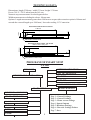
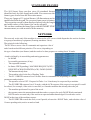
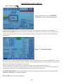
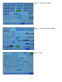
Z17160
SMART STOP
CS 969
TECHNICAL AND USER MANUAL
MANUEL TECHNIQUE & D’UTILISATION
SOCIETE CASSESE
SIEGE SOCIAL & USINE
ZONE INDUSTRIELLE 77390 VERNEUIL L’ETANG
FRANCE
06/ 2011 / version 3
Cassese / Communication
CS 969 SMART STOP
TECHNICAL DATA
1
PROGRAM DIAGRAM
1
UNPACKING, ASSEMBLY, ADJUSTEMENT, CONNECTING
2, 3, 4
USING THE 969 SMART STOP
- THE TOUCH SCREEN
5
- MOULDING WIDTH MEASURER
6
- CREATING / MODIFYING / DELETING A FILE
7, 8
EXECUTING A FILE
8
STANDARD FRAMES
9
NETWORK
9, 10
MAINTENANCE
11, 12, 13
Cassese / Communication
06 / 2011
TECHNICAL DATA
Dimensions: length 2390 mm / width 512 mm / height 1130 mm
Power: 380 V / 220 V taken from the 969 saw.
Numeric stop measurement: See the diagram below.
Width measurement excluding the rebate: 80 mm max.
Options: Length measurement greater than 1880 mm on request (the extension option is 900mm and
extends the external length up to 3000 mm) / bar-code reading - PC Connection.
MOULDING WIDTH MINI 10 INTER
2160 maxi
10 inter
90 int min. with moulding 10
MOULDING CUTTING PLANE
MOULDING WIDTH MAXI 150 INTER
1880 max with moulding 150
150 inter
90 mini with moulding 150
MOULDING CUTTING PLANE
PROGRAM OF SMART STOP
CS 969
ARTICLE CREATION
WELCOME
LIST OF ARTICLES
CHOICE OF LANGUAGES
SEARCH
NETLIST
CANCEL VERTICAL CLAMPS
MAIN MENU
MAINTENANCE
WIDTH MEASUREMENT
Page 1 : General Settings
Page 2 : General Settings
Page 3 : Home screen settings
Page 4 : Inputs Outputs
Page 5 : Database Settings
Page 6 : Barcode Settings/Printer
Page 7 : Docs
STANDARD FRAMES
MARIE LOUISE FUNCTION
EXT 3 M
INTER
EXTER
1
UNPACKING THE NUMERIC STOP (NS)
1
3
2
V1
V2
P1
P2
Open the crate and put the NS foot stand into an upright position.
With a 4mm hex head key, unscrew the 4 screws of the 2 foot stand locking plates: P1
and P2 . Push P1 and P2 right back with a mallet, then slide them down to the bottom
of each foot. Retighten the 4 screws of plates P1 and P2.
With a 5mm hex head key, unscrew V1 and V2 and put the NS feet in the outside
position as shown in figures 3 and 4.
4
ASSEMBLY OF THE NUMERIC STOP (NS)
The NS can only be assembled after the CS 969 has been made level on the ground. The right-hand extension and its support bracket have been dismantled and the 2 frame fastening screws are used.
THE FOLLOWING PROCEDURE REQUIRES AT LEAST TWO PEOPLE TO CARRY IT OUT
CUTTING
TABLE
CUTTING
TABLE
E
E
Take the NS out of the crate and turn it over. Place the bed of the NS on bracket E, and screw them together (10mm
long tubular socket wrench + 5mm hex head key) without tightening, using the 2 screws, 2 washers and 2 nuts
provided.
T3
T3
3
2
1
R1
1
R2
S1
Z
V1
GB
S2
Unlock locking screw Z and slide the guide GB of the NS
along screws 1-2-3 of the right-hand table and the nuts of the
2 ruler supports R1 and R2. Screw 3 should be visible in hole
T3. Tighten screws 1, 2, 3 and S1 and S2 of ruler supports R1
and R2 with a 4mm hex head key.
S2
R2
1
2
ADJUSTMENT OF THE NUMERIC STOP (NS)
GA
Z
Slide the NS head towards the cutting table and position plate GA
right next to screw VB1 (see fig 4: PR= reference position).
Tighten screw VB1 with a 4mm hex head key.
Repeat for the following screw (VB2), and so on for the other
screws up to the end of the NS.
TB
GB
VB1Fig 2
GA
TB
VB2
VB1
TB V2
PR
Lining up the stops:
In the accessories box is supplied a nylon wire and two screws with their nuts.
Run this wire against the inner face of the guide GB. Install one screw and two
nuts at the right extremity of the aluminium guide gb and attach to it the wire(see
picture bellow). Install the second extremity of the wire on its screw at the end of
the guide of the left arm. Unsing the nut of the screws holding the wire apply some
tension on the wire.
GB
VB1
PR
Left hand
extension
NS
NYLON WIRE
GUIDE GB
LEFT HAND
3
Proper adjustment:
1) The nylon wire is streched uniformly against the aluminium profile
2) There is no gap in the STOP/MACHINE joint (J).
If this is not the case, move the right extremity of the NS backward or forward
until the nylon wire is fully streched in line with the aluminium guide. Move the
NS left or right until the gap in the joint J disappears.
NYLON WIRE
STOP
Perpendicular level
(base)
CS 969
Table
J
Stop
fig 5
Horizontal
level
Levelling:
EH
With a 19mm open-end wrench, adjust the NS levels in relation to the
machine table by screwing and unscrewing nut EH of the NS feet.
Check the levels with a ruler.
After adjusting level alignment, tighten the nuts of bracket E
permanently (10mm tubular socket wrench + 5mm hex head key).
Remove the alignment nylon wire.
Insert the plug at the end of the aluminium profile.
CUTTING
TABLE
E
CONNECTING THE NUMERIC STOP
The NS has 3 DIN plugs to be connected to the machine, above the front right-hand foot.
1
2
3
1
2
3
MALE FEMALE
FEMALE
5P DIN
4P DIN
5P DIN
4
USING THE CS969 SMART STOP
The working of the numerical stop has almost no effect on saw operation.
The only information that is exchanged is:
- Disabling of stop movement if the blades move forward.
- The signal of the push button to measure the width of the moulding.
- The encoder value of the rebate measurement .
The 969 Smart Stop can store 3000 articles consisting of:
- A reference consisting of 16 numbers or letters.
- Moulding rebate bottom width.
- Frame width.
- Frame length.
- Edge position: Internal or external.
- The play to be added in case of inside measurement
- Position of vertical clamps (optional)
Furthermore, the 969 Quick Stop/Smart Stop can store 60 types of standard frames
identified only by their length and width dimensions.
Using the touch screen:
The 969 numerical stop is equipped with an intuitive touch screen for man/machine dialogue
The operating principle is the same as for other Cassese machines (CS4008XL & UNI).
Only necessary information appears on the screen and the buttons represent the only possible
choices. This makes the use of the screen much easier because the user is guided.
When the device detects a problem, the message is displayed until the problem is solved (e.g.
«EMERGENCY STOP», etc…)
At power-up, the ‘initialisation’ screen appears (program version, screen version, number of
cuts, as well as the choice of languages available).
The main menu appears by touching the screen.
5
MOULDING WIDTH MEASURER
G
0
MAINTENANCE
MEASURER BUTTON
AG AD
The main menu can display the
following alarm messages :
- STOP ORIGIN NOT SET
- CLAMP ORIGIN NOT SET
- EMERGENCY STOP
MAIN MENU
RAZ MESUR
When the EMERGENCY STOP message appears: switch the Emergency Stop button On, so that the stop
can be initialised. Caution ! : Risk of movement ! Remove any moulding that is on the machine table and
press the measurer button. Let the measurer press against the fixed G rule by pressing the measurer button
on the front of the saw. Then, still pressing the measurer button, touch the screen button RESET MEAS.
The Width Measurer origin is set.
If you have not done it correctly (e.g. there was a moulding!), you can still re-start the process from the
MAINTENANCE menu.
Once the origins have been initialised, place the moulding on the cutting table and press the measurer
button.
The width will be displayed in the measurer button.
If the button is pressed, the moulding measurement will be displayed in the field:
LRG MOUL (moulding width) (102.3 for example).
The position of the vertical numerical clamps (option) will be displayed in the field :
POS. PRESS (clamp) (4.2 for example)
The numerical clamps are then placed by default at the centre of the moulding. This position can then be
adjusted by pressing the «POS PRESS (clamp)» field. To cancel the vertical clamps press CANCEL
LEFT (AG) or CANCEL RIGHT (AD). This triggers the positioning of the vertical clamps forward,
above the guide rail of the stop, stopping it from touching the moulding.
6
CREATING/MODIFYING/DELETING A FILE
In the main menu, press the «ARTICLES» icon.
The articles menu appears:
All the parameters of creation / modification / deleting article are collected
together in this screen.
New
article
Search article
Deleting article
Validation
Enter the reference for your article (max = 16 digits) using the keypad after pressing the field «REF
ARTICLE/WORK» (for example here: GINO)
You can change all the values, by pressing each field and using the
numeric keypad. Here’s what the displayed dimensions represent:
- LRG MOUL: Moulding width at rebate bottom.
- LRG: Frame width.
- LNG: Frame length.
- POS PRESS : Position of the vertical clamps (optional)
- INTER EXTER : Edge position: Internal or external.
- ALLOWANCE : Functional clearance inside the frame.
This clearance is added to the internal measurement dimensions.
The external dimension is not affected by the clearance
EXTERNAL DIMENSION
INTERNAL DIMENSION
To Search for an article in the database, type in the desired reference in the Ref Article field, then press
the Search Article button.. The data is then displayed in the Article menu..
To delete an article in the database, type in the desired reference, then press the Delete key. The article
is removed from the database.
It is possible to Create a new article from an existing article (copy).
Find the existing article, modify the data, then after typing a new name in the Ref Article field, press V to
confirm. This new article is stored in the database.
By pressing the green button TO EXEC, the article settings are copied to the execution menu.
Conversely, one can copy the execution settings to the article menu by pressing the FROM EXEC
button.
GET DATE JMA: Specify here the date of creation of your article. When a new article
is created the date is automatically updated
7
Once the values have been filled in, you can either validate the article by pressing V, or you can
not validate it and return to the main menu screen by pressing the MAIN button
From the articles menu, you can similarly modify an existing article, delete an article, copy or
view the list of articles. By pressing the IDX button, you can check the position in the memory
of the machine of each article.
Press the ARTICLES LIST button to view the articles in lists of 10 (article name only). The
articles are not necessarily arranged in chronological order of entry. A removed article is in fact an
article with values 0000 (this program function can be found in CS4008XL and UNI).
ARTICLE
ARTICLE LIST
EXECUTING A FILE
Start from the main menu.
If the stop has not yet been initialised, it then
returns to its point of origin (Stop off-set). This
will be the only time there is an automatic reset
after power-up; thereafter, the position is
locked.
The main screen parameters are only the last to
be executed.
Going in the article screen, network screen
or article list will affect the execution
screen parameters only on request, by
touching button «TO EXECT».
RESEARCH
VALIDATION COUNTER
Similarly, you can enter the article you want and then run it by pressing the SEARCH button.
You can change a reference to be run by pressing V directly from the execution screen. You can
change the settings for execution by pressing the LRG (width), LNG (length, ALLOW (clearance),
LRG MOUL (moulding width) or STANDARD FRAME fields. This does not affect the parameters of
the stored articles, but only of those being run.
In all cases:
-The dimension is a function of the moulding width and of the measurement type : Internal or
External.
-When measurement is INTERNAL, the typical clearance is automatically added and can be
adjusted directly by pressing the ALLOW (clearance) button, located under the frame.
-The minimum and maximum dimensions allowed are function of the moulding width and
measurement type (internal or external)
-Press the keys in front of the frame to switch between length and width.
-Press the INTER/EXTER buttons to switch between internal and external measurement (unless
the external edge is locked - see parameters section).
-The dimensions are calculated for 45 ° .
-There is a cut counter that is incremented or decremented (see parameters section) each time the
blades STOP cutting. Press the COMPTEUR (counter) button to reset them to 0000. This
does not reset the general counter to 00000000 (first screen displayed at power-up).
--When a dimension that exceeds the capabilities of the stop is entered, the message «ALRM
POS. MIN or MAX» is displayed.
8
STANDARD FRAMES
The 969 Smart Stop can also store 60 standard frames
identified only by their length and width. You can access the
frame types screen from the Execution menu.
There are 4 pages of 15 typical frames. All dimensions can be
modified with the keypad. To execute a frame press its button.
The execution screen is then displayed where only the length
and width values of the frame type can be adjusted.
We can thus combine the frame types with the SMART STOP
measurements, or with an article in the memory.
NETWORK
The network works only if the machine is connected to a PC/server which dispatches the work to be done
to a group of machinery equipment (Framing machines / Saws).
The principle is the following:
The PC/Server stores a list of commands and organises a list of
tasks based on the different priorities. The server, depending on
the type of machine (saw/framer) and the work to be done prepares: a waiting list of 10 tasks.
A task is defined by its assembling and cutting parameters:
Its NAME
Its assembly parameters (if any).
The requested Amount.
Its Status: FREE (pending) / MACHINE REQUEST (GET) /
REQUEST ACKNOWLEDGED (ACK) / DONE (DONE).
The amount already done.
The machine asks for the list of Pending Tasks.
The PC / SERVER returns a list of 10 tasks from its commands list, depending on various
parameters and priorities.
The operator selects GET - Request for Tasks. 1 to 10 tasks may be requested by a machine.
The PC/SERVER returns a list of 10 tasks, with the ACK response if the request is accepted. It could
be refused, for example, if the order is cancelled, or if another machine has already taken the job.
The machine performs all or part of the work.
the operator enters the amount done and then makes a request for work-DONE Work terminated.
DONE can be executed only if the work was requested and acknowledged. Several tasks can be
DONE at the time of the machine request.
The PC/SERVER records the work, even if partial, releases the -DONE Tasks , and refreshes a list of
10 more pending tasks, and so on and so forth.
9
- The machines are connected to a PC server via a network cable (CAT5 Ethernet).
The link is of the RS485 series, the protocol is of the Modbus type. For certain distances, it is
better if a twisted cable be used (ETH CAT5 is appropriate). Other network architecture solutions can be considered: including that the PC server can be in Germany and the production in
China.
NETLIST
LIST OF ARTICLES
Press «NETLIST» in the main menu or on the article page. Press «UPDATE» to bring the list up
to date. Make your request GET / ACK or DONE.
Press «UPDATE» to bring the list up to date. Run the task and press «UPDATE» to bring the
list up to date. The NETLIST execution parameters may be used.
To view the task parameters, press on the name of the task.
Then press»> EXEC».
The machine sets itself up with the parameters of the NETLIST Task. Otherwise, do the Task
with your own settings, or with an article in the memory.
You can still press «DONE».
THE NETWORK PART IS SET TO CHANGE SEE EVOLUTION «Cassese BarCode»
10
MAINTENANCE MENU
MAINTENANCE
On the main menu, press MAINTENANCE to access the settings pages:
All values can be modified. There is no need to switch off the power for the new values to be acknowledged.
RESET MEASURER: Press the measurer button, and this key simultaneously to reset the measurer origin, if it has
not been set correctly. Make sure there is no moulding on the table, so the measurer can reach the front aluminium
cutting guide.
Page 1 : General Settings
STOP OFFSET: Position at which the numerical stop is initialised after each power-up, when EXECUTE is pressed
once. This edge can be checked by cutting a rod at 45 ° and measuring the Ogee side. These parameters may need readjustment after diassembly of the stop or the encoder.
Make sure that the stop is initialised 2-3 cm after the proximity sensor of the origin take-up area.
In case the NS doesn’t initialize correctly a loud noise could be amitted by the motor. Then slide the head of the stop
towards the cutting table. A click should be heard when the stop head passes this sensor.
EXTER DIMENSIONS : Press this button if you do not want the operator to work on outer edge (the
internal / external keys are then disabled).
PIN CODE: Reserved for maintenance.
11
Page 2: General Settings
STOP INIT and CLAMP INIT:
They re-initialise the stop or the clamps.
COUNTER INC MODE or COUNTER
DEC MODE:
They increase or decrease of the cut
counter on the main screen.
COUNTER DIVIDER: Used to count the
complete frame (4 cuts) or count the
number of cuts if its value is 1
Page 3: Welcome Screen Settings
- Choose the default language
- Update the date and time.
Page 4 : Inputs Outputs
12
Page 5 : Database Settings
Page 6 : Barcode Settings Printer
Page 7 : Docs
13