1
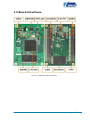
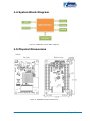
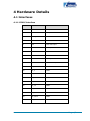
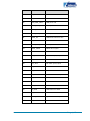
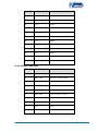
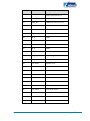
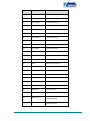
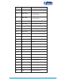
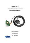
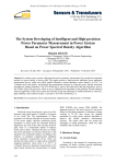
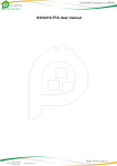
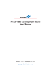
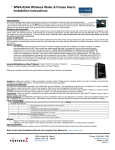
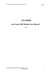
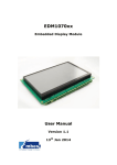
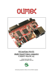
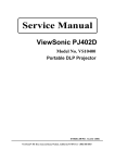
MINI1857 Core board User Manual Version 1.1 14th Jan 2014 Copyright Statement: MINI1857 and its related intellectual property are owned by Shenzhen Embest Technology Co., Ltd. Shenzhen Embest Technology has the copyright of this document and reserves all rights. Any part of the document should not be modified, distributed or duplicated in any approach and form without prior written permission issued by Embest Technology Co., Ltd. Revision History: Version Date Description 1.0 10/04/2013 Original Version 1.1 14/01/2014 Localisation Table of Contents 1 Product Overview .............................................................. 1 1.1 Introduction ....................................................................1 1.2 Kit Contents ....................................................................1 1.3 Board Interfaces ..............................................................2 1.4 System Block Diagram .....................................................3 1.5 Physical Dimensions .........................................................3 2 Hardware Features ............................................................ 4 2.1 Processor .......................................................................4 2.2 On-Board Memory ...........................................................5 2.3 Communication Interfaces ................................................5 2.4 Operational Parameters ....................................................5 3 Software Features ............................................................. 7 3.1 System Features .............................................................7 3.2 Development Environments ..............................................7 3.3 Debugging Tools ..............................................................7 4 Hardware Details ............................................................... 8 4.1 Interfaces .......................................................................8 4.1.1 CON1 Interface ......................................................................... 8 4.1.2 CON2 Interface ....................................................................... 11 4.1.3 SPI Flash Interface................................................................... 15 Appendix 1: ESD Precautions & Handling Procedures ......... 16 Appendix 2: Technical support & Warranty ........................ 17 2.1 Technical support service................................................ 17 2.2 Maintenance service clause ............................................. 18 2.3 Basic guidelines for protection and maintenance of LCDs .... 19 2.4 Value Added Services ..................................................... 20 1 Product Overview 1.1 Introduction The MINI1857 is an embedded core module built on LPC1857FET256 - a 32bit ARM Cortex-M3 microcontroller. By combining the MINI1857 with an expansion board from Embest (EDM1070xx or EDM1043xx) or other specifically designed boards built according to the hardware interfaces of the MINI1857, users can implement a quick function trimming so as to create a shorter time to market. 1.2 Kit Contents MINI1857 Core Board CD-ROM Four hex head cap screws Four brass tube plugs Optional EDM1070B-01 EDM1070BR-01 (with 4 wire resistive touchscreen) EDM1043B-01 EDM1043BR-01 (with 4 wire resistive touchscreen) Page | 1 1.3 Board Interfaces Figure 1: MINI1857 Board Interfaces Page | 2 1.4 System Block Diagram Figure 2: MINI1857 System Block Diagram 1.5 Physical Dimensions Figure 3: MINI1857 Physical Dimensions Page | 3 2 Hardware Features 2.1 Processor NXP LPC1857FET256 microcontroller based on 32-bit ARM Cortex-M3, operating at up to 180MHz Floating-point unit 1024KB Flash 136 KB SRAM 16KB EEPROM LCD controller with support for 24bpp true-colour mode and a resolution of up to 1024×768 USB 2.0 high-speed Host/Device/OTG interface with on-chip PHY and support for DMA transmission USB 2.0 high-speed Host/Device interface with on-chip PHY and ULPI which supports external high-speed PHY 10/100 Mbps Ethernet MAC MII/RMII interface Four-wire SPI flash interface (SPIFI) with data transfer rate of up to 40Mbps per channel Two CAN 2.0B Four UARTs Two I2S’ Two I2Cs Two SSPs SPI bus Four 32-bit general purpose timers Two standard PWMs Motor control PWM with Quadrature encoder interface Two 10-bit ADCs operating at up to 400KHz Page | 4 10-bit DAC operating at up to 400KHz 164 general-purpose I/O interfaces Two watchdog timers 2.2 On-Board Memory 128MB NAND Flash 32MB SDRAM 2KB EEPROM 4MB SPI Flash (spare solder pads) 2.3 Communication Interfaces Two SPI interfaces Three 3-wire UART interfaces Touch-screen interface (16-bit 256RGB) I2C interface I2S interface Two USB interfaces Two CAN interfaces SDIO interface 10/100Mbps Ethernet interface 2.4 Operational Parameters Operating Temperature: 0°C ~ 70°C Storage Temperature: -40°C ~ 85°C Operating Humidity: 0% ~ 90% (Non-condensing) Power Supply: 5V @ 0.8A, DC PCB Layers: 6 Top Layer Component Height MAX = 2 mm Page | 5 Bottom Layer Component Height Board Thickness =1.6mm MAX = 5 mm Page | 6 3 Software Features 3.1 System Features Supports: uC/OS-II_v2.91 operating system emWin5.18 graphic interface FatFs_vR0.08a filesystem LWIP _v1.4.0 protocol stack 3.2 Development Environments IAR EWARM Integrated Development Environment All drivers can work with IAR EWARM V6.40 or higher; Keil MDK-ARM Integrated Development Environment All drivers and applications can work with Keil MDK-ARM V4.60 or higher. 3.3 Debugging Tools ULINK2 ULINK2 is recommended to be used under Keil MDK-ARM for the best debugging performance; JLINK-V9.1 JLINK-V9.1 is recommended to be used under IAR EWARM for the best debugging performance Page | 7 4 Hardware Details 4.1 Interfaces 4.1.1 CON1 Interface Pin Name Function 1 VDD5V +5V power 2 VDD5V +5V power 3 VBAT_IN VBAT In 4 GND GND 5 TDI Test data input 6 nTRST Test system reset 7 TCK Test clock 8 TMS Test mode select 9 nRESET Test system reset 10 TDO Test data output 11 P1_4 GPIO 12 PC_2 GPIO 13 PC_3 GPIO 14 PC_9 GPIO 15 PC_11 GPIO 16 PC_12 GPIO 17 PC_13 GPIO 18 PC_14 GPIO 19 SD_DAT2 GPIO 20 SD_DAT3 GPIO Page | 8 Pin Name Function 21 SD_CMD GPIO 22 GND GND 23 SD_DAT0 Card data 0 24 SD_CLK Card Clock 25 SD_DAT1 Card data 1 26 SD_CD Card Command Signal 27 PD_0 GPIO 28 PD_1 GPIO 29 PD_2 GPIO 30 PD_3 GPIO 31 PD_4 GPIO 32 PD_5 GPIO 33 PD_6 GPIO 34 PD_7 GPIO 35 PD_8 GPIO 36 PD_9 GPIO 37 PD_10 GPIO 38 PD_11 GPIO 39 PD_12 GPIO 40 PD_13 GPIO 41 SPIFI_SIO2 SPIFI Data 2 42 P9_0 GPIO 43 P9_1 GPIO 44 P9_2 GPIO Page | 9 Pin Name Function 45 P9_3 GPIO 46 P9_4 GPIO 47 USB_PWR_FAULT USB power fail 48 USB1_PWR_EN USB1 power enable 49 USB1_DM USB1 bidirectional D+ line 50 USB0_PWR_EN USB0power enable 51 USB1_DP USB0 bidirectional D-line 52 P3_0 GPIO 53 USB0_PWR_FAULT USB0 power fail 54 USB1_VBUS VBUS drive signal 55 GND GND 56 I2C_SCL I2C clock input/output 57 U1_TXD UART1Transit data 58 I2C_SDA I2C data input/output 59 U1_RXD UART1 Receive data 60 U3_TXD UART3 Transit data 61 U1_TDR Data Terminal Ready 62 U3_RXD UART3 Receive data 63 U0_TXD UART0 Transit data 64 EMC_A9 EMC address line 9 65 U0_RXD UART0 Receive data 66 U2_TXD UART2 Transit data 67 CAN0_TD C_CAN transmit output 68 U2_RXD UART2 Receive data Page | 10 Pin Name Function 69 CAN0_RD C_CAN receive input 70 CAN1_TD C_CAN transmit output 71 PE_2 GPIO 72 CAN1_RD C_CAN receive input 73 PE_4 GPIO 74 PE_3 GPIO 75 PE_6 GPIO 76 PE_5 GPIO 77 PE_8 GPIO 78 PE_7 GPIO 79 PE_14 GPIO 80 PE_9 GPIO 4.1.2 CON2 Interface Pin Name Function 1 LED1_LINK/ACK LINK LED 2 ENET_TXN Ethernet Transmit Data 3 LED2_SPEED SPEED LED 4 ENET_TXP Ethernet Transmit Data 5 USB0_ID USB0 ID pin 6 ENET_RXN Ethernet Receive Data 7 USB0_VBUS VBUS pin 8 ENET_RXP Ethernet Receive Data 9 GND GND 10 GND GND Page | 11 Pin Name Function 11 USB0_DM - line 12 P4_3 GPIO 13 USB0_DP USB0 bidirectional D+ line 14 P4_0 GPIO 15 P4_1 GPIO 16 P4_4 GPIO 17 P8_0 GPIO 18 P8_1 GPIO 19 P8_2 GPIO 20 P8_8 GPIO 21 LCD_HSYNC Horizontal Sync Input 22 LCD_BL_EN LCD backlight 23 LCD_VSYNC Vertical Sync Input 24 LCD_DCLK Sample clock 25 LCD_PWR LCD power enable 26 GND GND 27 LCD_VD4 LCD panel data4 28 LCD_DE Data Input Enable 29 LCD_VD6 LCD panel data6 30 LCD_VD3 LCD panel data3 31 LCD_VD11 LCD panel data11 32 LCD_VD5 LCD panel data5 33 LCD_VD13 LCD panel data13 34 LCD_VD7 LCD panel data7 Page | 12 Pin Name Function 35 LCD_VD15 LCD panel data15 36 LCD_VD10 LCD panel data10 37 LCD_VD20 LCD panel data20 38 LCD_VD12 LCD panel data12 39 LCD_VD22 LCD panel data22 40 LCD_VD14 LCD panel data14 41 LCD_VD23 LCD panel data23 42 LCD_VD19 LCD panel data19 43 GND GND 44 LCD_VD21 LCD panel data21 45 ADC0 ADC input channel 0 46 ADC1 ADC input channel 1 47 ADC2 ADC input channel 2 48 ADC3 ADC input channel 3 49 ADC4 ADC input channel 4 50 ADC5 ADC input channel 5 51 ADC6 ADC input channel 6 52 ADC7 ADC input channel 7 53 WAKEUP0 Wakeup pin 0 54 WAKEUP1 Wakeup pin1 55 WAKEUP2 Wakeup pin 2 56 WAKEUP3 Wakeup pin 3 57 SPIFI_SCK 58 SPIFI_SC Serial clock for SPI/SSP0/SPIFI Slave Select for Page | 13 Pin Name Function SPI/SSP0/SPIFI Master In Slave Out for 59 SPIFI_MISO 60 SPIFI_MOSI 61 GND GND 62 SSP0_SSEL Slave Select for SSP0 63 SSP0_SCK Serial clock for SSP0 64 SSP0_MOSI Master Out Slave In for SSP0 65 SSP0_MISO Master In Slave Out for SSP0 66 TP_PENIRQ LCD Touch IRQ 67 TP_BUSY LCD Touch busy 68 PF_9 GPIO 69 P6_1 GPIO 70 P6_0 GPIO 71 P6_7 GPIO 72 P6_2 GPIO 73 SPIFI_SIO3 SPIFI Data 3 74 GND GPIO 75 P7_2 GPIO 76 CLK1 Clock output pin 1 77 P7_4 GPIO 78 CLK2 Clock output pin 2 79 P7_5 GPIO 80 CLK3 Clock output pin 3 SPI/SSP0/SPIFI Master Out Slave In for SPI/SSP0/SPIFI Page | 14 4.1.3 SPI Flash Interface Pin Name Function 1 SSP1_SSEL Slave Select for SSP1 2 SSP1_MISO Master In Slave Out for SSP1 3 VDD3V3(WP) +3.3V power 4 GND GND 5 SSPI1_MOSI Master Out Slave In for SSP1 6 SSP1_SCK Serial clock for SSP1 7 P7_3(HOLD) GPIO 8 VDD3V3 +3.3V power Page | 15 Appendix 1: ESD Precautions & Handling Procedures Please note that the board comes without any case/box and all components are exposed. Therefore, extra attention must be paid to ESD (electrostatic discharge) precautions. To effectively prevent electrostatic damage, please follow the steps below: Avoid carpets in cool, dry areas. Leave development kits in their anti-static packaging until ready to be installed. Dissipate static electricity before handling any system components (development kits) by touching a grounded metal object, such as the system unit unpainted metal chassis. If possible, use antistatic devices, such as wrist straps and floor mats. Always hold an evaluation board by its edges. Avoid touching the contacts and components on the board. Take care when connecting or disconnecting cables. A damaged cable can cause a short in the electrical circuit. Prevent damage to the connectors by aligning connector pins before you connect the cable. Misaligned connector pins can cause damage to system components at power-on. When disconnecting a cable, always pull on the cable connector or strain-relief loop, not on the cable itself. Warning: This is a class A product. In a domestic environment this product may cause radio interference in which case the user may be required to take adequate measures. Page | 16 Appendix 2: Technical support & Warranty Embest Technology Co., Ltd. established in March of 2000, is a global provider of embedded hardware and software. Embest aims to help customers reduce time to market with improved quality by providing the most effective total solutions for the embedded industry. In the rapidly growing market of high end embedded systems, Embest provides comprehensive services to specify, develop and produce products and help customers to implement innovative technology and product features. Progressing from prototyping to the final product within a short time frame and thus shortening the time to market, and to achieve the lowest production costs possible. Embest insists on a simple business model: to offer customers high-performance, low-cost products with the best quality and service. 2.1 Technical support service Embest provides one year of free technical support for all products. The technical support service covers: Embest embedded platform products software/hardware materials Assistance to customers with regards to compiling and running the source code we offer. Troubleshooting problems occurring on embedded software/hardware platforms if users have followed the instructions provided. Judge whether a product failure exists. The situations listed below are not covered by our free technical support service, and Embest will handle the situation at our discretion: Customers encounter issues related to software or hardware during their development process Page | 17 Issues occur when users compile/run the embedded OS which has been modified by themselves. Customers encounter issues related to their own applications. Customers experience problems caused by unauthorised alteration of our software source code 2.2 Maintenance service clause 1. Product warranty will commence on the day of sale and last 12 months provided the product is used under normal conditions 2. The following situations are not covered by the warranty, Embest will charge service fees as appropriate: Customers fail to provide valid proof of purchase or the product identification tag is damaged, unreadable, altered or inconsistent with the product. Products are subject to damage caused by operations inconsistent with their specification; Products are subject to damage in either appearance or function due to natural disasters (flood, fire, earthquake, lightning strike or typhoon) or natural aging of components or other force majeure; Products are subject to damage in appearance or function due to power failure, external forces, water, animals or foreign materials; Products malfunction due to disassembly or alteration of components by customers, or repair by persons or organizations unauthorized by Embest Technology, or alteration from factory specifications, or configured or expanded with components that are not provided or recognized by Embest Technology; Product failures due to the software or systems installed by customers, inappropriate software settings or computer viruses; Products purchased from unauthorized merchants; Page | 18 Embest Technology takes no responsibility for fulfilling any warranty (verbal or written) that is not made by Embest Technology and not included in the scope of our warranty. 3. Within the period of warranty, the cost for sending products to Embest should be paid by the customer. The cost for returning the product to the customer will be paid by Embest. Any returns in either direction occurring after the warranty period has expired should be paid for by the customer. 4. Please contact technical support with any repair requests. Note: Embest Technology will not take any responsibility for products returned without the prior permission of the company. 2.3 Basic guidelines for protection and maintenance of LCDs 1. Do not use finger nails or other hard sharp objects to touch the surface of the LCD 2. Embest recommends purchasing specialist wipes to clean the LCD after long time use, avoid cleaning the surface with fingers or hands as this may leave fingerprints or smudges. 3. Do not clean the surface of the screen with unsuitable chemicals Note: Embest do not supply a maintenance service for LCDs. We suggest the customer immediately checks the LCD once in receipt of the goods. In the event that the LCD does not run or shows no display, the customer should inform Embest within 7 business days of delivery. Page | 19 2.4 Value Added Services We will provide following value added services: Driver development based on Embest embedded platforms for devices such as: serial ports, USB interface devices, and LCD screens. Control system transplantation, BSP driver development, API software development. Other value added services including supply of power adapters and LCD parts. Other OEM/ODM services. Technical training. Please contact Embest with any technical support queries: http://www.embest-tech.com/contact-us.html Page | 20