1
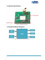
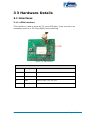
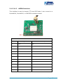
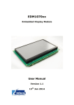
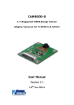
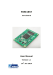
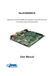
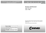
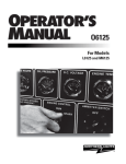
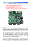
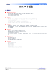
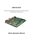
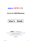
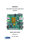
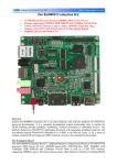
GPS8100-S A TI OMAP35X, AM37X and DM37X Compatible GPS Module User Manual Version 1.1 14th Jan 2014 Copyright Statement: Unless otherwise specified, the EDM1070xx series mentioned in this document includes but is not limited to the following products: EDM1070A-01, EDM1070AR-01, EDM1070B-01, and EDM1070BR-01. EDM1070xx and its related intellectual property are owned by Shenzhen Embest Technology Co., Ltd. Shenzhen Embest Technology has the copyright of this document and reserves all rights. Any part of the document should not be modified, distributed or duplicated in any approach and form without prior written permission issued by Embest Technology Co., Ltd. Revision History: Version Date Description 1.0 04/10/2012 Original Version 1.1 14/01/2014 Localisation Table of Contents 1 Product Overview .............................................................. 1 1.1 Introduction ....................................................................1 1.2 Kit Contents ....................................................................1 1.3 Board Interfaces ..............................................................2 1.4 System Block Diagram .....................................................2 2 Hardware Features ............................................................ 3 2.1 Product Features .............................................................3 3 3 Hardware Details ............................................................ 4 3.1 Interfaces .......................................................................4 3.1.1 4 PIN interface .......................................................................... 4 3.1.2 3.1.2 40PIN Interface .................................................................. 5 4 Linux System ..................................................................... 8 4.1 Preparation .....................................................................8 4.1.1 Hardware .................................................................................. 8 4.1.2 Software ................................................................................... 8 4.2 Start-up methods ............................................................8 4.3 Test Steps ......................................................................9 4.4 Resources Compilation ................................................... 10 5 WinCE System ................................................................. 11 5.1 Preparation ................................................................... 11 5.1.1 Hardware ................................................................................ 11 5.1.2 Software ................................................................................. 11 5.2 Start-up methods .......................................................... 11 5.3 Test Steps .................................................................... 12 Appendix 1: GPGGA Parameter Explanation ....................... 13 Appendix 2: GPGSV Parameter Explanation ........................ 15 Appendix 3: GPRMC Parameter Explanation ....................... 16 Appendix 4: GPVTG Parameter Explanation ........................ 17 Appendix 5: GPGSA Parameter Explanation ........................ 18 Appendix 6: ESD Precautions & Proper Handling Procedures19 Appendix 7: Technical support & Warranty ........................ 20 7.1 Technical support service ................................................ 20 7.2 Maintenance service clause ............................................. 21 7.3 Basic guidelines for protection and maintenance of LCDs .... 22 7.4 Value Added Services ..................................................... 23 1 Product Overview Figure 1: GPS8100-S Module 1.1 Introduction The GPS8100-S module is a GPS function module designed by Embest Technology. Based on the JRC GPS receiver module G591, which provides the best solution with the highest sensitivity and tracking performance in the world and also features the highest position and speed accuracy in urban conditions. The GPS8100-S module uses the latest surface mount and advanced integrated circuit technology, which not only obtains the best performance, but also reduces the products size and power consumption. The high-performance hardware and high intelligence software ensure the module has amazing compatibility; it is widely applied to all kinds of guidance products. 1.2 Kit Contents GPS8100-S Page | 1 1.3 Board Interfaces Figure 2: GPS8100-S Interfaces 1.4 System Block Diagram Figure 3: GPS8100-S System Block Diagram Page | 2 2 Hardware Features 2.1 Product Features L1 band (1575.42MHz) receiver Channel: supports up to 88 channels (with 66 search channels and 22 simultaneous tracking channels) Chipset: JRC GPS module Output data format: NMEA0183 V3.01 Position accuracy: 3 meters (without Aid)/2.5 meters(DGPS) Data Update cycle: One second Compatible with: DevKit8000, DevKit8500, SBC8530 2.2 Operational Parameters Operating Temperature: -40°C ~ 85°C Storage Temperature: -40°C ~ 125°C Operating Voltage: 1.8V ~ 3.3V Dimensions: 38x44 mm Cable Length:5M Start time o Hot Start (approximately): 1.5 seconds o Warm boot (approximately): 34 seconds o Cold start (approximately): 35 seconds Page | 3 3 3 Hardware Details 3.1 Interfaces 3.1.1 4 PIN interface This interface is used to transmit TTL level GPS data; it can connect to an evaluation board or a PC using RS232 level switching. Figure 4: 4 PIN Interface J2 Pin Signal Function Description 1 VDD3V3 3.3V power 2 TXB Transmit data, 3.3V, TTL level 3 RXB Receive data, 3.3V, TTL level 4 GND GND Page | 4 3.1.2 3.1.2 40PIN Interface This interface is used to transmit TTL level GPS data; it can connect to a Devkit8000, Devkit8500, or SBC8530 evaluation board. Figure 5: 40 PIN Interface J1 Pin Signal 1 GND 2 NC 3 NC 4 NC 5 NC 6 NC 7 NC 8 NC 9 NC 10 NC 11 UART1_RX Function Description GND UART1 receive data, 1.8V, TTL level Page | 5 J1 Pin Signal Function Description 12 UART1_TX UART1 transmit data, 1.8V, TTL level 13 GND GND 14 NC 15 NC 16 NC 17 NC 18 NC 19 NC 20 NC 21 NC 22 NC 23 NC 24 NC 25 NC 26 NC 27 NC 28 GND 29 NC 30 NC 31 NC 32 NC 33 NC 34 NC GND Page | 6 J1 Pin Signal Function Description 35 NC 36 NC 37 VDD33 3.3V 38 VDD18 1.8V 39 NC 40 GND GND Page | 7 4 Linux System 4.1 Preparation This section contains a guide to configuring the GPS8100-S for a compatible board. The following hardware and software is required: 4.1.1 Hardware Target board (DevKit8000, DevKit8500, SBC8530) GPS8100-S module GPS antenna TF card 5V power adapter Serial cable 4.1.2 Software Image (Target board\linux\image\) Testing tools (Package-GPS8100-S\linux\test-gps) 4.2 Start-up methods 1. Connect the serial cable to the PC and the target board. 2. Connect the GPS8100-S module to the expansion interface of the target board. 3. Connect the GPS antenna to the COM1 interface. 4. Copy the file test-gps (Package-GPS8100-S\linux\) to the TF card, and then insert it into the target board. 5. Power on the board. Page | 8 4.3 Test Steps 1. Run the Linux system then launch the program test-gps from the TF card. For the DevKit8000 evaluation board, run the following commands to launch the GPS8100-S module: root@DevKit8000:/# /media/mmcblk0p1/test-gps -d /dev/ttyS0 -b 9600 For the Devkit8500 evaluation board, run the following commands to launch the GPS8100-S module: root@DevKit8500:/# /media/mmcblk0p1/test-gps -d /dev/ttyS0 -b 9600 For the SBC8530 evaluation board, run the following commands to launch the GPS8100-S module: root@SBC8530:/# /media/mmcblk0p1/test-gps -d /dev/ttyS1 -b 9600 Note: When executing commands, please refer to the relevant manual of your target board, and select the UART port. Both DevKit8000 and DevKit8500 use UART1 (ttyS0) as their expansion interface The SBC8530 uses UART2 (ttyS1) as its expansion interface 2. The HyperTerminal window will display the following information after executing the command from step 1. ctrl + c to exit! $GPGSA,A,3,03,06,19,23,,,,,,,,,4.1,4.0,1.0*3E $GPGSV,3,1,12,25,79,244,,07,68,311,,11,62,180,18,19,44,025,20*70 $GPGSV,3,2,12,08,29,323,18,13,26,226,,03,22,043,36,06,13,046,21*77 $GPGSV,3,3,12,23,12,191,28,28,09,301,,16,03,095,,20,03,173,*76 $GPRMC,012345.000,A,2234.2758,N,11408.0677,E,0.00,,261109,,,A*79 $GPVTG,,T,,M,0.00,N,0.0,K,A*13 $GPGGA,012346.000,2234.2758,N,11408.0677,E,1,04,No data 4.0,69.0,M,-1.7,M,,0000*7F Page | 9 $GPGSA,A,3,03,06,19,23,,,,,,,,,4.1,4.0,1.0*3E $GPRMC,012346.000,A,2234.2758,N,11408.0677,E,0.00,,261109,,,A*7A $GPVTG,,T,,M,0.00,N,0.0,K,A*13 $GPGGA,012347.000,2234.2758,N,11408.0677,E,1,04,No data Note: Press CONTROL+C to quit the test More information about GPS parameters is available in the Appendix. 4.4 Resources Compilation The directory Package-GPS8100-S\linux\ contains the file test-gps.c; the resource compilation is shown as below using the DevKit8000 as an example: 1. Install cross-compilation environment Insert the DevKit8000 DVD into the computer; execute the following command to extract the cross-compilation tools: cd /media/cdrom/linux/tools tar xvjf arm-2007q3-51-arm-none-linux-gnueabi-i686.tar.bz2 -C /home/embest 2. Implement cross-compilation Execute the following command to add the cross compiler tool to the environment variable export PATH=/home/embest/arm-2007q3/bin:$PATH Copy test-gps.c to the Linux system on the PC; execute the following command to generate an executable image arm-none-linux-gnueabi-gcc test-gps.c -o test-gps Note: For other target boards please refer to the relevant documentation Page | 10 5 WinCE System 5.1 Preparation This section contains a guide to getting the GPS8100-S working with a compatible board. The following hardware and software is required: 5.1.1 Hardware Target board (DevKit8000, DevKit8500, SBC8530) GPS8100-S module GPS antenna TF card 5V power adapter Serial cable 5.1.2 Software Testing tools (Package-GPS8100-S\wince\GPSviewer.rar) 5.2 Start-up methods 1. Connect the serial cable to the PC and the target board. 2. Connect the GPS8100-S module to the expansion interface of the target board. 3. Connect the GPS antenna to the COM1 interface. 4. Extract the file GPSviewer.rar from the directory Package-GPS8100-S\wince\, Copy the folder GPSviewer to the TF card, and then insert the TF card into the target board. 5. Power on the board Page | 11 5.3 Test Steps 1. Run the system and launch the application GpsViewer.exe (The application is in the Directory “\Storage Card\GPSviewer”). 2. Configure the application GpsViewer.exe option as below: Select COM1 port; Select baud rate of 9600; Click “GPS” The application GpsViewer.exe will receive the GPS data after finishing the procedure. Page | 12 Appendix 1: GPGGA Parameter Explanation GGA: Essential fix data which provides 3D location and accuracy data. $GPGGA,123519,4807.038,N,01131.000,E,1,08,0.9,545.4,M,46.9, M,,*47 Where: GGA Global Positioning System Fix Data 123519 Fix taken at 12:35:19 UTC 4807.038,N Latitude 48 deg 07.038' N 01131.000,E Longitude 11 deg 31.000' E 1 Fix quality: 0 = invalid 1=GPS fix (SPS) 2=DGPS fix 3=PPS fix 4=Real Time Kinematic 5=Float RTK 6=Estimated (dead reckoning) (2.3 feature) 7 = Manual input mode 8 = Simulation mode 08 Number of satellites being tracked 0.9 Horizontal dilution of position 545.4, M Altitude, Meters, above mean sea level 46.9, M Height of geoid (mean sea level) above WGS84 Page | 13 ellipsoid (Empty field) time in seconds since last DGPS update (Empty field) DGPS station ID number *47 the checksum data, always begins with * Page | 14 Appendix 2: GPGSV Parameter Explanation GSV: Shows data about the satellites that the unit might be able to find based on its viewing mask and almanac data $GPGSV,2,1,08,01,40,083,46,02,17,308,41,12,07,344,39,14,22,2 28,45*75 Where: GSV Satellites in view 2 Number of sentences for full data 1 Sentence 1 of 2 08 Number of satellites in view 01 Satellite PRN number 40 Elevation, degrees 083 Azimuth, degrees 46 SNR - higher is better for up to 4 satellites per sentence *75 the checksum data, always begins with * Page | 15 Appendix 3: GPRMC Parameter Explanation RMC: NMEA has its own version of essential GPS PVT (position, velocity, time) data. It is called RMC and will look similar to: $GPRMC,123519,A,4807.038,N,01131.000,E,022.4,084.4,230394, 003.1,W*6A Where: RMC Recommended Minimum sentence C 123519 Fix taken at 12:35:19 UTC A Status A=active or V=Void. 4807.038,N Latitude 48 deg 07.038' N 01131.000,E Longitude 11 deg 31.000' E 022.4 Speed over the ground in knots 084.4 Track angle in degrees True 230394 Date - 23rd of March 1994 003.1,W Magnetic Variation *6A The checksum data, always begins with * Page | 16 Appendix 4: GPVTG Parameter Explanation VTG - Velocity made good. The GPS receiver may use the LC prefix instead of GP if it is emulating Loran output. $GPVTG,054.7,T,034.4,M,005.5,N,010.2,K*48 Where: VTG Track made good and ground speed 054.7,T True track made good (degrees) 034.4,M Magnetic track made good 005.5,N Ground speed, knots 010.2,K Ground speed, Kilometres per hour *48 Checksum Page | 17 Appendix 5: GPGSA Parameter Explanation $GPGSA,A,3,04,05,,09,12,,,24,,,,,2.5,1.3,2.1*39 Where: GSA Satellite status A Auto selection of 2D or 3D fix (M = manual) 3 3D fix - values include: 1 = no fix 2 = 2D fix 3 = 3D fix 04,05... PRNs of satellites used for fix (space for 12) 2.5 PDOP (dilution of precision) 1.3 Horizontal dilution of precision (HDOP) 2.1 Vertical dilution of precision (VDOP) *39 the checksum data, always begins with * For more information, please visit: http://www.gpsinformation.org/dale/nmea.htm Page | 18 Appendix 6: ESD Precautions & Proper Handling Procedures Please note that the board comes without any case/box and all components are exposed. Therefore, extra attention must be paid to ESD (electrostatic discharge) precautions. To effectively prevent electrostatic damage, please follow the steps below: Avoid carpets in cool, dry areas. Leave development kits in their anti-static packaging until ready to be installed. Dissipate static electricity before handling any system components (development kits) by touching a grounded metal object, such as the system unit unpainted metal chassis. If possible, use antistatic devices, such as wrist straps and floor mats. Always hold an evaluation board by its edges. Avoid touching the contacts and components on the board. Take care when connecting or disconnecting cables. A damaged cable can cause a short in the electrical circuit. Prevent damage to the connectors by aligning connector pins before you connect the cable. Misaligned connector pins can cause damage to system components at power-on. When disconnecting a cable, always pull on the cable connector or strain-relief loop, not on the cable itself. Warning: This is a class A product. In a domestic environment this product may cause radio interference in which case the user may be required to take adequate measures. Page | 19 Appendix 7: Technical support & Warranty Embest Technology Co., Ltd. established in March of 2000, is a global provider of embedded hardware and software. Embest aims to help customers reduce time to market with improved quality by providing the most effective total solutions for the embedded industry. In the rapidly growing market of high end embedded systems, Embest provides comprehensive services to specify, develop and produce products and help customers to implement innovative technology and product features. Progressing from prototyping to the final product within a short time frame and thus shortening the time to market, and to achieve the lowest production costs possible. Embest insists on a simple business model: to offer customers high-performance, low-cost products with the best quality and service. 7.1 Technical support service Embest provides one year of free technical support for all products. The technical support service covers: Embest embedded platform products software/hardware materials Assistance to customers with regards to compiling and running the source code we offer. Troubleshooting problems occurring on embedded software/hardware platforms if users have followed the instructions provided. Judge whether a product failure exists. The situations listed below are not covered by our free technical support service, and Embest will handle the situation at our discretion: Customers encounter issues related to software or hardware during their development process Page | 20 Issues occur when users compile/run the embedded OS which has been modified by themselves. Customers encounter issues related to their own applications. Customers experience problems caused by unauthorised alteration of our software source code 7.2 Maintenance service clause 1. Product warranty will commence on the day of sale and last 12 months provided the product is used under normal conditions 2. The following situations are not covered by the warranty, Embest will charge service fees as appropriate: Customers fail to provide valid proof of purchase or the product identification tag is damaged, unreadable, altered or inconsistent with the product. Products are subject to damage caused by operations inconsistent with their specification; Products are subject to damage in either appearance or function due to natural disasters (flood, fire, earthquake, lightning strike or typhoon) or natural aging of components or other force majeure; Products are subject to damage in appearance or function due to power failure, external forces, water, animals or foreign materials; Products malfunction due to disassembly or alteration of components by customers, or repair by persons or organizations unauthorized by Embest Technology, or alteration from factory specifications, or configured or expanded with components that are not provided or recognized by Embest Technology; Product failures due to the software or systems installed by customers, inappropriate software settings or computer viruses; Products purchased from unauthorized merchants; Page | 21 Embest Technology takes no responsibility for fulfilling any warranty (verbal or written) that is not made by Embest Technology and not included in the scope of our warranty. 3. Within the period of warranty, the cost for sending products to Embest should be paid by the customer. The cost for returning the product to the customer will be paid by Embest. Any returns in either direction occurring after the warranty period has expired should be paid for by the customer. 4. Please contact technical support with any repair requests. Note: Embest Technology will not take any responsibility for products returned without the prior permission of the company. 7.3 Basic guidelines for protection and maintenance of LCDs 1. Do not use finger nails or other hard sharp objects to touch the surface of the LCD 2. Embest recommends purchasing specialist wipes to clean the LCD after long time use, avoid cleaning the surface with fingers or hands as this may leave fingerprints or smudges. 3. Do not clean the surface of the screen with unsuitable chemicals Note: Embest do not supply a maintenance service for LCDs. We suggest the customer immediately checks the LCD once in receipt of the goods. In the event that the LCD does not run or shows no display, the customer should inform Embest within 7 business days of delivery. Page | 22 7.4 Value Added Services We will provide following value added services: Driver development based on Embest embedded platforms for devices such as: serial ports, USB interface devices, and LCD screens. Control system transplantation, BSP driver development, API software development. Other value added services including supply of power adapters and LCD parts. Other OEM/ODM services. Technical training. Please contact Embest with any technical support queries: http://www.embest-tech.com/contact-us.html Page | 23