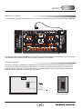
1
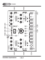
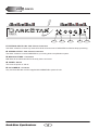
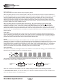
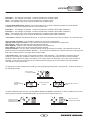
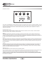
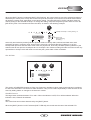
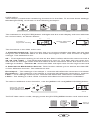
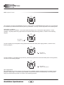
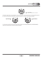
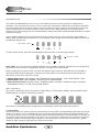
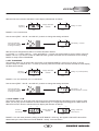
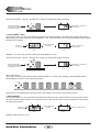
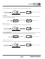
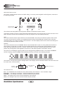
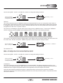
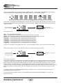
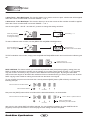
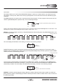
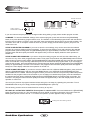
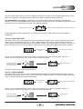
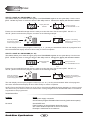
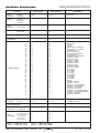
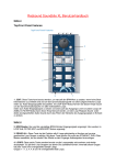
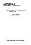
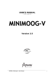
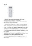
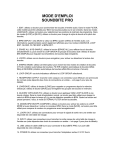
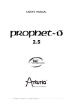
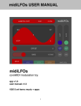
INTRODUCTION
DARKSTAR SYNTHESIS
DarkStar
8 VOICE POLYPHONIC SYNTHESIZER
Thank you for purchasing the RED Sound DARKSTAR 8-voice polyphonic synthesizer.
The Analogue Synthesiser, mainstay of Seventies' and Eighties' music, is back, reinvented in a new, more reliable
and flexible form. Physical modelling via powerful DSPs (Digital Signal Processors) allow all the warmth and control
of the synthesizers of yesteryear without the problems of unstable tuning and unrepeatable sounds, and with
modern benefits like realtime control and multitimbral access.
Welcome to DARKSTAR, an 8-voice polyphonic synthesiser with all the highlights of the analogue tradition, Pulse
Width Modulation, Ring Mod, Resonant Filtering and ADSR Enveloping, combined with all the advantages of
modern MIDI instruments like rock-solid tuning, perfect program recall, velocity response and 5 different timbres
simultaneously available.
So whether your aim is to recreate 'classic' timbres like 70's Disco Bassline / Screaming PWM Lead, chart new
sonic territory with realtime joystick manipulation of ring modulation and velocity controlled resonance, or even
combine both approaches in the same MIDI sequence, DARKSTAR is the perfect tool for you.
In the future, DARKSTAR's capabilities will grow thanks to the ability to change its EPROM-based DSP algorithms.
This will allow you to convert DARKSTAR into many different products such as a mega-mono synthesizer or
vocoder.
But DARKSTAR already offers so much with its marriage of proven synthesis techniques and state-of-the-art
control. Now it's time to unlock the potential of analogue-style synthesis with modern control techniques in your
music.
Be creative!
1
OWNERS MANUAL
DarkStar Synthesizer
2
7
3
1
Min
AUDITION
(SHIFT)
(SHIFT)
(OSC 2 PITCH)
WAVEFORM
SPEED
5
MENU
DOWN
VALUE
RAMP
(MIDI CLOCK)
0
(PWM)
0
16
17
PULSE WIDTH
Min
EDIT
TRI
Max
VALUE
MENU
UP
LFO1
OSCILLATORS
1
19
FILTER
2
RANDOM
24
0
10
8 VOICE POLYPHONIC SYNTHESIZER
11
3
1
UTILITY
2
4
LFO
OSC 1
Min
Max
6
MENU
PROG
PART SELECT
3
MIXER
Min
Max
4
OSC 2
PART
5
PROG
RING
MODULATION
EDIT
PARAMETER
/VALUE
BANK
Min
5
PORTA/TRIGGER
6
5
PART
OUTPUT
DarkStar
EXT.
INPUT
OUTPUT
+2
Semitones
LEVEL
OUTPUT
DETUNE
-2
Semitones
SHAPE
Max
SAMPLE
LFO2
PULSE
LFO SHAPE
SINE
DELAY
Oscillator2
LFO’s
SQUARE
Min
Oscillator 1
Oscillators
OSC 2 SEMITONE OFFSET
7
12
+10
PITCH MOD
Max
-10
www.redsound.com
RED
12
ATTACK
LEVEL
9
(FILTER TYPE)
1
MIDI
7
OFF
BAND
(RES MOD)
(0)
5
SUSTAIN
Off
TREMOLO
ENV1
MODULATION
8
Filter Off
ENV2
LFO1
BANK
Filter On
(SHIFT)
Max
8
PROGRAM
(SHIFT)
+10
LFO2
(LFO 2 MOD)
7
(VELOCITY)
RELEASE
PORTAMENTO
Min
ENV MOD
0
RES MOD SOURCE
Filter
HI
-10
6
Max
+
Envelope 2
(+10)
RESONANCE
(-10)
Envelope 1
FILTER TYPE
LO
4
Min
-
VELOCITY LEVEL
3
Max
+
Envelopes
2
DECAY
Off
PANNING
Max
Min
FREQUENCY
Min
0
Max
-
4
2
FRONT PANEL
FRONT PANEL FEATURES
FRONT PANEL FEATURES
1. OSCILLATORS: This section features [WAVEFORM], [PITCH MOD], [PULSE WIDTH] and [DETUNE] controls
for each oscillator. The large [OSCILLATOR] button switches between oscillators 1 & 2. The [SHIFT] button is used
to access the [OSC 2 PITCH] and [PWM] controls in the oscillator sub-menu.
2. ENVELOPES: This section features [ATTACK], [DECAY], [SUSTAIN] and [RELEASE] controls for each
envelope. The large [ENVELOPE] button switches between envelopes 1 & 2. The [SHIFT] button is used to access
the [VELOCITY] control in the envelope sub-menu.
3. LFO’S: This section features [SPEED], [DELAY] and [SHAPE] controls for each LFO. The large [LFO] button
switches between LFO 1 & 2. The [SHIFT] button is used to access the [MIDI CLOCK] control in the LFO submenu.
4. FILTER: This section features [FREQUENCY], [RESONANCE] and [ENV MOD] controls for the filter. The large
[FILTER] button switches the filter on and off. The [SHIFT] button is used to access the [FILTER TYPE], [RES MOD]
and [LFO 2 MOD] controls in the oscillator sub-menu.
5. PART SELECT: These buttons are used to select the 5 Multitimbral ‘PARTS’. You can create and store 5 totally
different sounds in each program.
6. MENU: This section features 8 menu buttons and a 4-way keypad. The MENU buttons are used to select
additional parameters for editing whilst the [EDIT] keypad is used to scroll up and down the menu and change the
values.
7. AUDITION: This button can be used to trigger the currently selected PART.
8. PROGRAM: This section features the [PROGRAM] and [BANK] buttons which are used to select the 8 banks of
8 programs (total programs = 64).
9. PART OUTPUT: This button is used to access the [LEVEL], [PANNING], [TREMOLO] and [PORTAMENTO]
parameters for each individual PART.
10. PARAMETER/VALUE DISPLAY: This 4-digit LED display shows bank/program numbers, parameter
information and edit values.
11. MIXER: The joystick mixer adjusts the balance between OSCILLATORS 1 and 2 (or external input) and also
sets the amount of RING MODULATION.
12. UTILITY: This button is used to access the SYSTEM EXCLUSIVE utility parameters.
3
OWNERS MANUAL
REAR PANEL
DarkStar
RED
EXT.
INPUT
OUT
MIDI
1
ON
POWER
L
-
8 VOICE POLYPHONIC SYNTHESIZER
2
www.redsound.com
R
THRU
OUT
2
OFF
9v DC
CAUTION: DO NOT OPEN CASE
REFER TO QUALIFIED SERVICE PERSONNEL
NO USER SERVICEABLE PARTS INSIDE
RED Sound Systems Ltd
1
IN
+
MADE IN ENGLAND
3
4
5
1. EXTERNAL INPUTS 1&2 - RCA Phono Connectors
Use these sockets to connect any external line level sound sources to DARKSTAR for filter/envelope processing.
2. STEREO OUTPUT - RCA Phono Connectors
Use these sockets to connect DARKSTAR to your mixing desk or amplification system.
3. MIDI IN/OUT/THRU - Connectors
MIDI data will be transmitted and received by these connectors.
4. POWER - Switch
This turns the power on and off.
5. DC POWER IN - Connector
Only use the 9vDC 800 mA PSU supplied with DARKSTAR to power the unit.
DarkStar Synthesizer
4
www.redsound.com
RED
STUDIO MIXING DESK
8 VOICE POLYPHONIC SYNTHESIZER
DarkStar
EXTERNAL MIDI DRIVEN SOUND SOURCE 2
EXTERNAL MIDI DRIVEN SOUND SOURCE 1
OUT
R
L
THRU
5
MIDI IN
R
OTHER MIDI DEVICE
L
RED Sound Systems Ltd
2
1
EXT.
INPUT
OUT
MIDI
OFF
+
9v DC
-
POWER
MIDI IN
MIDI SEQUENCER
MIDI KEYBOARD
MIDI OUT
MADE IN ENGLAND
CAUTION: DO NOT OPEN CASE
REFER TO QUALIFIED SERVICE PERSONNEL
NO USER SERVICEABLE PARTS INSIDE
IN
ON
TO
AC WALL
SOCKET
RED PSU
CONNECTIONS
OWNERS MANUAL
QUICK START
QUICK START
If you want to quickly try out the performance of DARKSTAR, please read the following points carefully:
CONNECTIONS: Before making any connections, make sure that the power on all your equipment is turned OFF.
Connect the power supply (included) to the ‘power in’ socket on the rear panel of DARKSTAR and plug it into a
suitable AC outlet. Connect the audio cables for a basic system setup as shown on page 5.
TURNING ON THE POWER: Make sure all connections have been made correctly and the volume controls on the
mixing desk and amplifier system are turned completely down. Press the rear panel power switch on DARKSTAR.
Turn on the power of the mixing desk and then turn on the power of the amplifier system.
POWER UP INDICATIONS: When DARKSTAR is powered up, the main display will show the software version
whilst various parameters are being set internally. When this process is complete, the display will show the BANK
and PROGRAM number. If this does not happen, check the power supply is of the correct type and the unit was
switched on correctly.
SETTING THE MIDI RECEIVE CHANNEL: To select the correct MIDI receive channel press the [MIDI] MENU
button and use the [EDIT] keypad [VALUE +] and [VALUE -] buttons to set the channel of the active PART (as
DARKSTAR can have up to 5 different sounds/MIDI channels setup in each PROGRAM you may have to change
the MIDI transmit channel on your keyboard a few times to play all the sounds).
SELECTING A PROGRAM: To select the factory programs in BANK 1, press and hold the [PROGRAM] button
(LED on) and then press one of the buttons marked 1-8. To select one of the other 7 banks of 8 programs press
and hold the [PROGRAM] button then press the [BANK] button. Now you can select one of the 8 programs in the
new bank using the buttons marked 1-8 (keep your finger on the [PROGRAM] button at all times when selecting
programs/banks).
NOTE: Banks 1 to 6 (48 programs) feature factory presets that demonstrate the sonic power of DARKSTAR.
Programs in banks 7 and 8 all contain the same basic sound ready for you to overwrite with newly created sounds.
Use the [AUDITION] button or connected MIDI keyboard to trigger the sounds. You can modify the sounds in realtime by altering the controls in the OSCILLATOR, FILTER, ENVELOPE and LFO sections.
Please read the following “OPERATION” section carefully to fully appreciate the range of features and facilities the
DARKSTAR 8-Voice Synthesizer has to offer.
GETTING STARTED
After connecting DARKSTAR to your system as detailed on page 5, press in the power switch on the rear panel to
turn the power on. As the software is initialising (takes approximately 12 seconds) rows of indicators will light in
sequence and the version number fitted to your unit will be shown on the main display:
BANK
PROG
Software version = 1.01
PARAMETER
VALUE
Afterwards, the last selected program (before power was switched off at the previous session) will be recalled and
displayed as follows:
BANK
PROG
Bank 4
Program 6
PARAMETER
VALUE
DarkStar Synthesizer
6
OPERATION
OSCILLATOR SECTION
0
+10
-10
WAVEFORM
0
Min
PITCH MOD
(OSC 2 PITCH)
(PWM)
0
5
7
Max
-2
Semitones
PULSE WIDTH
12
16
17
+2
Semitones
DETUNE
19
24
OSC 2 SEMITONE OFFSET
(SHIFT)
Oscillators
Oscillator 1
Oscillator2
This section of DARKSTAR produces the musical tones which form the basis of subtractive synthesis. There are
two oscillators per ‘voice’ (musical note), each producing audible vibrations to act as a sound source. The timbre of
each oscillator depends on its harmonic content which is determined by the waveform. There are basically two
waveforms available, SAWTOOTH and RISING, each with its own specific set of harmonics.
Controls for changing the amount of modulation to the pitch timbre of the oscillators are also included in this
section. These timbral and pitch modulations give the oscillator sound more depth and stimulate musical appeal to
the ear.
OSCILLATOR SELECT button
This large button switches between oscillator 1 and 2. When the indicator is OFF, oscillator 1 will be selected.
When the indicator is ON, oscillator 2 will be selected.
WAVEFORM (OSC 2 PITCH)
This control has two functions determined by the [SHIFT] button.
When the [SHIFT] function is NOT selected (SHIFT LED Off), this control sets the selected oscillator’s waveform.
At the fully anti-clockwise position (
) the waveform will be shaped like a SAWTOOTH. This waveform contains
every harmonic in decreasing volume and produces a very rich sound. As the control is moved in a clockwise
direction the shape progressively changes, becoming more and more ‘squared-off’ until, at the fully clockwise
position ( ) the shape will be a SQUARE or ‘pulse’ waveform. As a pure square wave (max and min values equal)
the harmonic content will be all the odd-numbered harmonics in decreasing volume which gives the sound a hollow
or ‘woody’ timbre. The width of the pulse can also be altered by the [PULSE WIDTH] knob to make the sound
thinner.
When the [SHIFT] function is selected (SHIFT LED Flashing), this control sets the amount of oscillator 2 pitch
offset. This detune setting is calibrated in semitones with the eight indicators labelled [OSC 2 SEMITONE OFFSET]
showing the value, as in the following example:
WAVEFORM
Example:
Oscillator 2 pitch offset =
12 semitones (1 octave)
Press once
before changing
the setting
(OSC 2 PITCH)
0
5
7
12
16
17
19
24
OSC 2 SEMITONE OFFSET
(SHIFT)
7
Oscillators
OWNERS MANUAL
OPERATION
PITCH MOD (PWM)
This control has two functions determined by the [SHIFT] button.
When the [SHIFT] function is NOT selected (SHIFT LED Off), this control sets the amount of pitch modulation to
the selected oscillator. At the 12 o’clock position there will be no pitch modulation applied. As the knob is moved in
an anti-clockwise direction the pitch modulation will become negative, first falling then rising. At the fully anticlockwise position the modulation will be at its maximum negative depth. As the knob is moved in a clockwise
direction from the centre position, the pitch modulation will become positive, first rising then falling. At the fully
clockwise position the modulation will be at its maximum positive depth. See [OSCILLATOR] menu section below
for further details on the pitch modulation source.
When the [SHIFT] function is selected (SHIFT LED Flashing), this control sets the amount of pulse width
modulation or PWM for the selected oscillator when its [WAVEFORM] is set to SQUARE ( ). The PWM
SOURCE can be set to LFO1, LFO2, ENV1 or ENV2 (see [OSCILLATOR] menu) with negative and positive
modulations available. At the 12 o’clock position there will be no PWM. As the knob is moved in an anti-clockwise
direction the variation in the pulse width will become more and more pronounced in a negative manner. As the
knob is moved in a clockwise direction the variation in the pulse width will become more and more pronounced in a
positive manner.
PULSE WIDTH
This control sets the actual width of the pulse. At the fully anti-clockwise position the fundamental will be at its
minimum producing an extremely thin sound. As the knob is moved in a clockwise direction the pulse width gets
wider, with progressively less high harmonics being added giving the sound a fuller timbre. At the fully clockwise
position the minimum and maximum values of the pulse width will be equal.
DETUNE
This control sets the fine tuning for each oscillator. At the 12 o’clock position the oscillators tuning will be
unaffected. As the knob is moved in an anti-clockwise direction the oscillators tuning will become more ‘Flat’, with a
total negative detune of - 2 semitones available at the fully anti-clockwise position. As the knob is moved in a
clockwise direction the oscillators tuning will become more ‘Sharp’, with a total positive detune of + 2 semitones
available at the fully clockwise position. Small variations in the oscillators relative tuning will fatten up a sound
giving it a rich texture. Larger amounts of detuning create a more extreme effect.
OSCILLATOR MENU
This section contains the remaining functions for the oscillators. To access these settings, press the MENU button
labelled [OSCILLATORS], as shown in the following example:
VALUE
MENU
UP
MENU
DOWN
VALUE
EDIT
OSCILLATORS
FILTER
OUTPUT
LFO
PART
PORTA/TRIGGER
MIDI
MODULATION
MENU
The indicator in the [OSCILLATOR] button will light and the main display will now alternate between the first
function and its current value, as shown below:
BANK
PROG
Function =
Pitch Modulation
source
BANK
PROG
Display alternates
between
PARAMETER
VALUE
First selection =
Envelope 1
PARAMETER
VALUE
There are 4 functions in the oscillator menu with multiple settings as detailed in the following paragraphs.
1. Pitch Modulation Source: This function allows you to derive the selected oscillator’s PITCH modulation from
one of four different sources. The selections are:
DarkStar Synthesizer
8
OPERATION
Envelope1 - The settings of envelope 1 controls will affect the oscillators pitch.
Envelope 2 - The settings of envelope 2 controls will affect the oscillators pitch.
LFO1 - The settings of the LFO1 controls will affect the oscillators pitch.
LFO2 - The settings of the LFO2 controls will affect the oscillators pitch.
2. Pulse Width Modulation source: This function allows you to link the selected oscillator’s PULSE WIDTH
modulation to one of four different sources. The selections are:
Envelope1 - The settings of envelope 1 controls will affect the oscillators pulse width modulation.
Envelope 2 - The settings of envelope 2 controls will affect the oscillators pulse width modulation.
LFO1 - The settings of the LFO1 controls will affect the oscillators pulse width modulation.
LFO2 - The settings of the LFO2 controls will affect the oscillators pulse width modulation.
3. Oscillator 2 source: This function allows you to select the sound source for OSCILLATOR 2. The selections are:
Type 1(normal oscillator) - This oscillator contains the full range of frequencies.
Type 2(Formant style oscillator) - This oscillator is formed from a limited band of frequencies.
Noise1(Pink) - PINK noise has the higher frequencies reduced.
Noise 2(White) - WHITE noise and has all frequencies at an equal level.
Noise 3(Blue) - BLUE noise has the lower frequencies reduced.
External Input1&2 - You can switch off all the internal sound generators for oscillator 2 and instead use the rear
panel connectors marked [EXTERNAL INPUTS 1 - 2] to process any MIDI driven external sound source through the
filter and envelope sections. See page 29 for further details.
4. Oscillator Sync: This function synchronises oscillator 2 with oscillator 1. The oscillator 2 waveform will now
restart its cycle each time oscillator 1 starts its own cycle. The result of this keeps the pitch of both oscillators
identical making a distinct change to the timbre. For the best results use envelope 2 to try and move the pitch of
oscillator 2. The pitch cannot change but you will hear timbral changes to the sound with vocal characteristics.
The selections are: ON and OFF.
To change the current oscillator menu setting, use the [EDIT] keypad [VALUE +] and [VALUE - ] buttons as shown in
the following example:
Press 3 times
to change value
VALUE
MENU
UP
MENU
DOWN
VALUE
EDIT
BANK
OSCILLATORS
PROG
Function =
Pitch Modulation
source
BANK
PROG
Display alternates
between
New Pitch Mod Source =
LFO2
PARAMETER
VALUE
PARAMETER
VALUE
To select a different menu function, use the [MENU DOWN and [MENU UP] buttons. To EXIT oscillator menu mode,
simply press the [OSCILLATOR] MENU button and check that the indicator goes out.
VALUE
VALUE
Press the UP and
DOWN buttons to
select MENU functions
MENU
UP
MENU
UP
Press once to exit
oscillator menu mode
MENU
DOWN
MENU
DOWN
VALUE
VALUE
EDIT
EDIT
OSCILLATORS
9
OSCILLATORS
OWNERS MANUAL
OPERATION
ENVELOPE SECTION
LEVEL
PANNING
-
Min
Max
Max
+
Min
Max
DECAY
0
1
2
PORTAMENTO
Off
-
+
Min
ATTACK
TREMOLO
Off
Min
SUSTAIN
3
4
5
Max
RELEASE
(VELOCITY)
6
7
VELOCITY LEVEL
Envelopes
Envelope 1
(SHIFT)
Envelope 2
This section of DARKSTAR is used to shape the sound over a period of time with two envelopes available. The first
envelope is fixed to amplitude (or volume) and decides how quickly the sound starts, sustains and then fades away.
The second envelope can be used to control the filter frequency, pulse width or pitch modulations to alter the
character of the sound.
ENVELOPE SELECT button
This large button switches between envelope 1 and 2. When the indicator is OFF, envelope 1 will be selected.
When the indicator is ON, envelope 2 will be selected.
ATTACK
This control sets the time period for the envelope to reach its maximum after a note is played. At the fully anticlockwise position the response is virtually instantaneous giving a percussive edge to the sound. As the knob is
moved in a clockwise direction the time to reach maximum gradually increases giving a softer start to the sound. At
the fully clockwise position the attack time will be at its maximum.
DECAY
This control sets the rate at which the envelope falls to the [SUSTAIN] level after the maximum [ATTACK] level has
been reached. At the fully anti-clockwise position the response is virtually instantaneous. As the knob is moved in a
clockwise direction the decay duration gradually increases until, at the fully clockwise position the decay time will
be at its maximum.
SUSTAIN
This control sets the level of the envelope after the decay element is completed and until the note is released. At
the fully anti-clockwise position the envelope will continue to decay to zero without interruption. As the knob is
moved in a clockwise direction the level at which the decay ends gradually increases until, at the fully clockwise
position the sustain level will be at its maximum.
RELEASE (VELOCITY)
This control has two functions determined by the [SHIFT] button.
When the [SHIFT] function is NOT selected (SHIFT LED Off), this control sets the time taken for the sustain level to
reach zero once the note has been released. At the fully anti-clockwise position the response is virtually
instantaneous giving an abrupt end to the sound. As the knob is moved in a clockwise direction the release time
gradually increases resulting in a softer, more natural end to the sound. At the fully clockwise position the release
time will be at its maximum.
DarkStar Synthesizer
10
OPERATION
When the [SHIFT] function is selected (SHIFT LED Flashing), this control sets how much the selected envelope is
affected by the velocity level. Firmly struck notes will open the envelope to its maximum level whilst softer strokes
will produce a lesser result, dependent on the velocity setting. The eight VELOCITY LEVEL indicators show the
velocity setting for the selected envelope. To change the setting, first press the [SHIFT] button and then move the
[VELOCITY] knob. The indicators will show the value, as shown in the following example:
Min
Max
RELEASE
(VELOCITY)
0
1
2
3
4
5
6
Example: Envelope 1 velocity setting = 5
7
VELOCITY LEVEL
Envelopes
Envelope 1
Press once
before changing
the setting
(SHIFT)
Envelope 2
At the fully anti-clockwise position [indicator 0] there will be no velocity effect, with soft and hard notes each
producing the same, maximum result. As the knob is moved in a clockwise direction [indicators 1 to 6 ] the
envelope will open less and less when softer notes are played until, at the fully clockwise position [indicator 7] the
softest notes will not open the envelope at all. On envelope 1 this maximum setting will make soft notes sound very
quiet whilst on envelope 2 this will result in much less pitch, pulse width or filter modulation.
LFO SECTION
Min
Max
Min
SPEED
Max
DELAY
SHAPE
(MIDI CLOCK)
RAMP
TRI
SQUARE
SINE
PULSE
SAMPLE
RANDOM
LFO SHAPE
(SHIFT)
LFO’s
LFO1
LFO2
This section of DARKSTAR features 2 LFOs (Low Frequency Oscillators) which make regular electronic variations,
too low to be heard when converted into audio vibrations. They can be used independently to alter elements of the
sound by adding vibrato or changes to the harmonic content.
LFO SELECT button
This large button switches between LFO1 and 2. When the indicator is OFF, LFO1 will be selected. When the
indicator is ON, LFO2 will be selected.
SPEED
This control has two functions determined by the [SHIFT] button.
When the [SHIFT] function is NOT selected (SHIFT LED Off), this control sets the rate of the selected LFO.
11
OWNERS MANUAL
OPERATION
At the fully anti-clockwise position the speed will be at its slowest. As the knob is moved in a clockwise direction the
speed gradually increases until, at the fully clockwise position the LFO rate will be at its maximum.
When the [SHIFT] function is selected (SHIFT LED Flashing), this control is used to synchronise the LFO with an
external MIDI clock. The trigger rate can be set to a range of values from 1/8th beat to 4 bars in duration. At the
fully anti-clockwise position the LFO to MIDI synchronisation feature will be OFF. As the knob is moved in a
clockwise direction the trigger rate becomes less frequent until, at the fully clockwise position the LFO will cycle
once every 4 bars.
To view the setting, press the [SHIFT] button. The main display will now show the current value, as shown in the
following example:
BANK
PROG
LFO to MIDI clock
trigger rate = every ½ beat
PARAMETER
VALUE
To change the setting move the [MIDI CLOCK] knob. The main display will show the new value.
Range = OFF, 1/8bt,1/6bt, 1/4bt, 1/3bt, 1/2bt, 2/3bt, 3/4bt, 1bt, 2bt, 3bt, 1bar, 1.5 bars, 2 bars, 3 bars, 4 bars.
DELAY
This control sets the time taken for the LFO to be introduced after a note is struck. At the fully anti-clockwise
position the LFO will start immediately. As the knob is moved in a clockwise direction the delay period before the
LFO starts will gradually increase until, at the fully clockwise position the delay time will be at its maximum.
SHAPE
This control selects the waveform which determines the contour of the LFO modulation. There are 8 waveforms to
choose from as follows:
RAMP
TRI
SQUARE
SINE
PULSE
SAMPLE&HOLD
RANDOM
[
[
[
[
[
[
[
]
]
]
]
]
]
]
SHAPE
RAMP
TRI
SQUARE
SINE
PULSE
SAMPLE
LFO 1 waveshape = Sine
RANDOM
LFO SHAPE
LFO’s
LFO1
LFO2
LFO MENU
This section contains the remaining functions for the LFOs. To access the LFO settings, press the MENU button
labelled [LFO], as shown in the following example:
VALUE
MENU
UP
MENU
DOWN
VALUE
EDIT
OSCILLATORS
FILTER
OUTPUT
LFO
PART
PORTA/TRIGGER
MIDI
MODULATION
MENU
The indicator in the [LFO] button will light and the main display will now alternate between the first function and its
current value, as shown below:
BANK
PROG
Function =
Key Synchronisation
BANK
PROG
Display alternates
between
PARAMETER
VALUE
DarkStar Synthesizer
Setting = ON
PARAMETER
VALUE
12
OPERATION
The first function in the LFO menu is:
1. Key Synchronisation: This function sets the LFOs to start from the beginning of the selected waveform each
time a note is played. The selections are:
Off - The waveforms of all LFOs are synchronised but will be free running.
On - The waveforms of all LFOs are synchronised but will re-start from the beginning of the selected waveshape
each time a note is played.
To EXIT LFO menu mode, simply press the [LFO] MENU button and check that the indicator goes out.
Press once to exit
LFO menu mode
LFO
OUTPUT
PART
FILTER SECTION
(0)
Min
(-10)
Max
FREQUENCY
LO
(+10)
-10
RESONANCE
(FILTER TYPE)
OFF
0
BAND
HI
(LFO 2 MOD)
ENV1
FILTER TYPE
+10
ENV MOD
(RES MOD)
ENV2
LFO1
LFO2
RES MOD SOURCE
Filter
Filter Off
(SHIFT)
Filter On
This section of DARKSTAR features a classic 12dB per octave filter which, in subtractive synthesis, is used to
remove unwanted frequencies. There are three different types of filter to choose from, LOW PASS, BAND PASS
and HIGH PASS or the filter can be totally switched off.
FILTER SELECT button
This large button switches the filter on and off. When the indicator is OFF the filter will be bypassed. When the
indicator is ON the filter will be active.
FREQUENCY (FILTER TYPE)
This control has two functions determined by the [SHIFT] button.
When the [SHIFT] function is NOT selected (SHIFT LED Off), this control sets the basic cut-off frequency of the
filter. The affect this control has on the sound depends on the type of filter selected (low, band or high-pass), as
detailed in the following paragraph.
When the [SHIFT] function is selected (SHIFT LED Flashing), this control selects the FILTER TYPE. The four
indicators labelled FILTER TYPE show the current setting at all times. To change the filter type, first press the
[SHIFT] button and then move the [FILTER TYPE] knob. The indicators will show the value, as shown in the
following example:
13
OWNERS MANUAL
OPERATION
Min
Max
FREQUENCY
Example: Filter type = High Pass
(FILTER TYPE)
OFF
LO
BAND
HI
ENV1
FILTER TYPE
ENV2
LFO1
LFO2
RES MOD SOURCE
Filter
Filter Off
(SHIFT)
Filter On
Press once
before changing
the setting
At or near the fully anti-clockwise position the LOW PASS filter type will be selected:
LOW-PASS: This type of filter allows the low frequency elements to pass whilst reducing the higher frequencies as
the FREQUENCY control is moved anti-clockwise.
About the 12 o’clock position the BAND PASS filter type will be selected:
BAND-PASS: This type of filter allows a limited band of frequencies to pass whilst reducing the remaining high and
low frequencies, the filtered frequency band being set by the position of the FREQUENCY control.
At or near the fully clockwise position the HIGH PASS filter type will be selected:
HIGH-PASS: This type of filter allows the high frequency elements to pass whilst reducing the lower frequencies as
the FREQUENCY control is moved clockwise.
RESONANCE (RES MOD)
This control has two functions determined by the [SHIFT] button.
When the [SHIFT] function is NOT selected (SHIFT LED Off), this control sets the boost level of the frequencies
around the cut-off point as set by the FREQUENCY control. At the fully anti-clockwise position there is no boost. As
the control is moved in a clockwise direction the frequencies will be gradually increased until, at the fully clockwise
position, the resonance will reach self-oscillation producing a new pitched element similar to acoustic feedback.
When the [SHIFT] function is selected (SHIFT LED Flashing), this control sets the level of resonance modulation.
At the 12 o’clock position there will be no resonance modulation. As the knob is moved in an anti-clockwise
direction the amount of resonance modulation will become more and more pronounced in a negative manner. As
the knob is moved in a clockwise direction the amount of resonance modulation will become more and more
pronounced in a positive manner - see [FILTER] MENU below for details on selecting the resonance modulation
source.
ENV MOD (LFO 2 MOD)
This control has two functions determined by the [SHIFT] button.
When the [SHIFT] function is NOT selected (SHIFT LED Off), this control sets the amount of change (depth) of the
cut-off frequency as set by the FREQUENCY control. At the 12 o’clock position there will be no change to the filter
cut-off frequency. As the control is moved in an anti-clockwise direction the filter will be increasingly opened by the
audio modulation in a negative manner. As the knob is moved in a clockwise direction from the centre position the
filter will be increasingly opened by the audio modulation in a positive manner.
When the [SHIFT] function is selected (SHIFT LED Flashing), this control sets the level of LFO 2 modulation. At the
12 o’clock position there will be no LFO 2 modulation applied. As the knob is moved in an anti-clockwise direction
LFO 2 modulation will be applied more and more in a negative manner. As the knob is moved in a clockwise
direction from the centre position LFO 2 modulation will be applied more and more in a positive manner.
DarkStar Synthesizer
14
OP
FILTER MENU
This section contains the remaining functions for the filter. To access these settings
labelled [FILTER], as shown in the following example:
VALUE
MENU
UP
MENU
DOWN
VALUE
EDIT
OSCILLATORS
FILTER
OUTPUT
LFO
PART
PORTA/TRIGGER
MENU
The indicator in the [FILTER] button will light and the main display will now alternate
its current value, as shown below:
BANK
PROG
BANK
PRO
Display alternates
between
Function =
Keyboard tracking
PARAMETER
VALUE
PARAMETER
VALUE
The functions in the filter menu are:
1. Keyboard tracking: This function lets you choose whether the filter has the sam
range or has a different effect on the lower and higher notes. This function is applie
change. The selections are:
0ff - The keyboard tracking is off and so the filter’s effect will be the same across a
25, 50, 100, 150% - The keyboard tracking is now on. The filter will now open incr
and more for the high notes until the effect is at its maximum when the level is set t
settings included, - 25 and -50 where the filter will open less for the high notes and
2. Resonance Modulation Source: This function allows you to derive the filter RE
of four different sources. The selections are:
Envelope1 - The settings of envelope 1 controls will affect the resonance modulat
Envelope 2 - The settings of envelope 2 controls will affect the resonance modula
LFO1 - The settings of the LFO1 controls will affect the resonance modulation.
LFO2 - The settings of the LFO2 controls will affect the resonance modulation.
To select a different menu function, use the [MENU UP and [MENU DOWN] button
BANK
VALUE
Press the UP and
DOWN buttons to
select MENU functions
PRO
MENU
UP
MENU
DOWN
VALUE
EDIT
PARAMETER
VALUE
OSCILLATORS
To EXIT filter menu mode, simply press the [FILTER] MENU button and check that
Press o
FILTER
OSCILLATORS
FILTER
15
OUTPUT
OPERATION
MIXER Joystick Control
RING
MODULATION
Max
Max
Min
Min
OSC 1
OSC 2
MIXER
The centrally mounted joystick [MIXER] control is a unique feature of DARKSTAR which allows you to mix between
the oscillators (or external sound sources) and ring modulation ‘on-the-fly’ for extra expression and creative power.
OSCILLATOR 1-2 MIXING
The balance between oscillators 1 & 2 can be varied according to the ‘X’ axis (left-to-right) position. To hear
oscillator 1 by itself position the joystick knob at the South-West (lower left) position, as shown in the following
diagram:
RING
MODULATION
Max
Max
Mix position =
Oscillator 1 only
Min
Min
OSC 1
OSC 2
MIXER
To hear oscillator 2 by itself position the joystick knob at the South-East (lower right) position, as shown in the
following diagram:
RING
MODULATION
Max
Max
Min
Min
OSC 1
OSC 2
Mix position =
Oscillator 2 only
MIXER
To hear oscillator 1 & 2 together at equal levels, position the joystick knob at the due-South (lower centre) position,
as shown in the following diagram:
RING
MODULATION
Max
Max
Min
Min
OSC 1
OSC 2
Mix position =
Oscillator 1&2 balanced
MIXER
RING MODULATION
Ring modulation occurs when the two sound sources are multiplied together and this gives the resultant sound a
powerful, metallic edge. To introduce ring modulation on both sound sources simultaneously, move the joystick
away from the due-South position, as shown in the following example:
DarkStar Synthesizer
16
OPERATION
RING
MODULATION
Max
Max
Min
Min
OSC 1
OSC 2
Ring Modulation =
maximum setting on both sound sources
MIXER
To introduce high levels of ring modulation on one sound source more than the other, move the joystick away from
the centre line towards the North-West or North-East positions, as shown in the following example:
RING
MODULATION
Ring Modulation =
mainly oscillator 1
Max
RING
MODULATION
Max
Max
Max
Min
Min
Min
Min
OSC 1
OSC 2
OSC 1
OSC 2
MIXER
Ring Modulation =
mainly oscillator 2
MIXER
Try moving the joystick around its axis whilst making changes to the filter [FREQUENCY] and [RESONANCE]
controls to hear how these controls react with one another.
17
OWNERS MANUAL
OPERATION
MULTITIMBRAL PARTS
This section of DARKSTAR lets you to set up to five different sounds on each program for multiple sound
generation. You can specify the number of voices, note range, transposition, MIDI channel and other parameters
for each individual sound so that for instance, a fat dirty bass sound can be played right alongside a warm string
sound simultaneously on the same keyboard. When connected to a MIDI sequencer you can really get the
maximum sound generating power out of DARKSTAR by setting each PART to different MIDI channels for complex
synthesizer layering.
The five [PARTS SELECT] buttons grouped beneath the joystick mixer are used to select the active PART for
editing. When a [PART] button indicator is on, any changes to the front panel controls and/or MENU functions will
be applied to that part only.
Current PART = PART 1
1
2
3
4
5
PART SELECT
To select another PART, press the required [PART] button as shown in the following example:
New PART = PART 4
1
2
3
4
5
PART SELECT
PART COPY: You can copy all the parameter settings from one PART to another. This allows you to quickly build
up powerful unison sounds on a single MIDI channel - see page 26 for further details.
Before creating the sound for a PART you must first setup the basic ‘structure’ which defines how the PART is
played and what limitations will apply in relation to the other PARTS. The following functions and associated
parameters can be set for each part, namely:
1. [MENU] PART button: POLYPHONY, KEY TRANSPOSE, NOTE RANGE - LOW, NOTE RANGE - HIGH
2. [MENU] MIDI button: MIDI CHANNEL, SUSTAIN, PITCH BEND RANGE,
3. [PART OUTPUT] button: OUTPUT LEVEL, PANNING LEVEL / SOURCE, TREMOLO LEVEL / SOURCE
PORTAMENTO LEVEL / TYPE, AUTO-GLIDE ON/OFF
MENU - PART button
This section contains the first four functions for PART editing. To access these settings, press the MENU button
labelled [PART], as shown in the following example:
VALUE
MENU
UP
MENU
DOWN
VALUE
EDIT
OSCILLATORS
FILTER
OUTPUT
LFO
PART
PORTA/TRIGGER
MIDI
MODULATION
MENU
The indicator in the [PART] button will light and the main display will show the first function which is:
1: POLYPHONY
This function allows you set the maximum note allocation for each PART. The DARKSTAR synthesizer has a total
number of 8 notes or ‘voices’ available and you must carefully allocate these between the different PARTS so as
not to leave unused voices on one PART whilst missing notes played (because of under-allocation) on another. As
an example, a bass sound will probably only require one or two notes to be played at any one time so it would be
extremely wasteful to allocate any higher number of voices to this type of sound. Also, this will leave a greater
number of spare voices for parts where you want to use chords.
DarkStar Synthesizer
18
OPERATION
With this first menu function selected the main display will alternate as follows:
BANK
PROG
BANK
PROG
Display alternates
between
Function =
Polyphony
PARAMETER
VALUE
Setting = 6 voices
PARAMETER
VALUE
RANGE = 0 to 8 notes/voices
Use the menu [EDIT - VALUE + and VALUE -] buttons to change the setting as follows:
BANK
VALUE
Press the [VALUE+]
and [VALUE -] buttons
to change the setting
PROG
MENU
UP
New setting = 2 voices
MENU
DOWN
VALUE
EDIT
PARAMETER
VALUE
OSCILLATORS
With all 8 voices assigned there will be no further allocation allowed.
e.g. if PART 1 = 3 voices, PART 2 = 1 voice and PART 3 = 4 voices you will be unable to set any further voices for
PARTS 4 and 5. If you wish to create an additional PART, go back and lower the voice allocation for the existing
PARTS or setup another PROGRAM.
2: KEY TRANSPOSE
This function allows you to change the musical key of the selected PART by moving it up or down, in single
semitone steps to a maximum of +/- 24 notes (2 octaves). With the second menu function selected the main display
will alternate as follows:
BANK
PROG
BANK
PROG
Display alternates
between
Function =
Key Transpose
PARAMETER
VALUE
Setting = 0 (no transposition)
PARAMETER
VALUE
RANGE = 0 to +24 semitones, 0 to -24 semitones
Use the menu [EDIT - VALUE + and VALUE -] buttons to change the setting as follows:
BANK
VALUE
Press the [VALUE+]
and [VALUE -] buttons
to change the setting
PROG
MENU
UP
New setting = - 12
(transposed down 1 octave)
MENU
DOWN
VALUE
EDIT
PARAMETER
VALUE
OSCILLATORS
3: NOTE RANGE - LOW
This function allows you to set the LOW note range for the selected PART. By allocating groups of notes to each
PART you can play up to five different sounds simultaneously on a single keyboard using just one MIDI channel.
With the third menu function selected the main display will alternate as follows:
BANK
PROG
BANK
PROG
Display alternates
between
Function =
Note Range LOW
PARAMETER
VALUE
Setting = MIDI note
value 60 (C3)
PARAMETER
VALUE
RANGE = 0 to 100 notes (limited by setting of NOTE RANGE - HIGH e.g. the highest LOW NOTE value will be
determined by the note value set in NOTE RANGE - HIGH) - see next section.
19
OWNERS MANUAL
OPERATION
Use the menu [EDIT - VALUE + and VALUE -] buttons to change the setting as follows:
BANK
VALUE
PROG
MENU
UP
Press the [VALUE+]
and [VALUE -] buttons
to change the setting
New setting = MIDI note
value 36 (C1)
MENU
DOWN
VALUE
EDIT
PARAMETER
VALUE
OSCILLATORS
4: NOTE RANGE - HIGH
This function allows you to set the HIGH note range for the selected PART. The lowest HIGH NOTE value will be
determined by the note value set in NOTE RANGE - LOW. With the fourth menu function selected the main display
will alternate as follows:
BANK
PROG
BANK
PROG
Display alternates
between
Function =
Note Range HIGH
Setting = MIDI note
value 72 (C4)
PARAMETER
VALUE
PARAMETER
VALUE
RANGE = 0 to 100 notes (limited by setting of NOTE RANGE -LOW).
Use the menu [EDIT - VALUE + and VALUE -] buttons to change the setting as follows:
BANK
VALUE
PROG
MENU
UP
Press the [VALUE+]
and [VALUE -] buttons
to change the setting
New setting = MIDI note
value 96 (C6)
MENU
DOWN
VALUE
EDIT
PARAMETER
VALUE
OSCILLATORS
MENU - MIDI button
This section contains three PART functions related to MIDI. To access these settings, press the MENU button
labelled [MIDI], as shown in the following example:
VALUE
MENU
UP
MENU
DOWN
VALUE
EDIT
OSCILLATORS
FILTER
OUTPUT
LFO
PART
PORTA/TRIGGER
MIDI
MODULATION
MENU
The indicator in the [MIDI] button will light and the main display will show the first function which is:
1: MIDI CHANNEL
This function allows you to set the MIDI transmit/receive channel for the selected PART. The front panel controls
will transmit MIDI controller data on the selected channel. With the first menu function selected the main display
will alternate as follows:
BANK
PROG
BANK
PROG
Display alternates
between
Function =
MIDI Channel
PARAMETER
VALUE
PARAMETER
VALUE
RANGE = MIDI channel 1 to 16
DarkStar Synthesizer
Setting = MIDI channel 1
20
OPERATION
Use the menu [EDIT - VALUE + and VALUE -] buttons to change the setting as follows:
BANK
VALUE
Press the [VALUE+]
and [VALUE -] buttons
to change the setting
PROG
MENU
UP
New setting = MIDI channel 16
MENU
DOWN
VALUE
EDIT
PARAMETER
VALUE
OSCILLATORS
2: SUSTAIN
This function allows you to apply MIDI sustain to the selected PART. With the second menu function selected the
main display will alternate as follows:
BANK
PROG
BANK
PROG
Display alternates
between
Function =
Sustain
PARAMETER
VALUE
Setting = Sustain OFF
PARAMETER
VALUE
RANGE = Off and On
Use the menu [EDIT - VALUE + and VALUE -] buttons to change the setting as follows:
BANK
VALUE
Press the [VALUE+]
and [VALUE -] buttons
to change the setting
PROG
MENU
UP
New setting = Sustain ON
MENU
DOWN
VALUE
EDIT
PARAMETER
VALUE
OSCILLATORS
3: PITCH BEND RANGE
This function allows you to set the effective range of a controller keyboard’s Pitch Bend wheel when used to ‘bend’
the selected PART. With the third menu function selected the main display will alternate as follows:
BANK
PROG
BANK
PROG
Display alternates
between
Function =
Pitch Bend
PARAMETER
VALUE
Setting = No pitch bend
PARAMETER
VALUE
RANGE = 0 to 12 (1 octave)
Use the menu [EDIT - VALUE + and VALUE -] buttons to change the setting as follows:
BANK
VALUE
Press the [VALUE+]
and [VALUE -] buttons
to change the setting
PROG
MENU
UP
New setting = 12 semitones
MENU
DOWN
VALUE
EDIT
PARAMETER
VALUE
OSCILLATORS
21
OWNERS MANUAL
OPERATION
PART OUTPUT button/knobs
This section contains further functions for PART editing. To access, press the [PART OUTPUT] button, as shown in
the following example:
LEVEL
PANNING
-
Min
Max
Max
+
Min
Max
DECAY
0
1
2
PORTAMENTO
Off
-
+
Min
ATTACK
TREMOLO
Off
Min
SUSTAIN
3
4
5
Max
RELEASE
(VELOCITY)
6
7
VELOCITY LEVEL
Press to access
PART OUTPUT
Envelopes
PART
OUTPUT
Envelope 1
(SHIFT)
Envelope 2
The indicator below the [PART OUTPUT] button will flash to indicate this mode is active.
CAUTION!: as these controls are shared with the ENVELOPE section care must be taken to check the status of the
PART OUTPUT indicator before attempting to make any changes to the associated parameters.
LEVEL
This control sets the relative output LEVEL for the selected PART. At the fully anti-clockwise position there will be
no sound. As the control is moved in a clockwise direction the level will be gradually increased until, at the fully
clockwise position, the output level will be at its maximum. The main display will show the volume level setting from
0 to 127(max) when this control is moved.
PANNING
This control sets the amount of PANNING effect for the selected PART. At the 12 o’clock position there will be no
panning effect. As the knob is moved in an anti-clockwise direction the panning effect will be applied more and
more, with initial emphasis to the LEFT channel. As the knob is moved in a clockwise direction from the centre
position the panning effect will be applied more and more, with initial emphasis to the RIGHT channel.
The source for modulating the panning effect can be changed using a MENU function. To access the PANNING
OUTPUT settings, press the MENU button labelled [OUTPUT], as shown in the following example:
VALUE
MENU
UP
MENU
DOWN
VALUE
EDIT
OSCILLATORS
FILTER
OUTPUT
LFO
PART
PORTA/TRIGGER
MIDI
MODULATION
MENU
The indicator in the [OUTPUT] button will light and the main display will now alternate between the first function and
its current value, as shown below:
BANK
PROG
PROG
Display alternates
between
Function =
Panning source
The selections are:
BANK
PARAMETER
VALUE
Setting = Envelope 1
PARAMETER
VALUE
Pot - The PANNING knob will affect the pan position directly. Anti-clockwise = Left, clockwise = Right.
Envelope1 - The settings of envelope 1 controls will affect the pan position.
Envelope 2 - The settings of envelope 2 controls will affect the pan position.
LFO1 - The settings of the LFO1 controls will affect the pan position.
LFO2 - The settings of the LFO2 controls will affect the pan position.
DarkStar Synthesizer
22
OPERATION
Use the menu [EDIT - VALUE + and VALUE -] buttons to change the setting as follows:
BANK
VALUE
Press the [VALUE+]
and [VALUE -] buttons
to change the setting
PROG
MENU
UP
New setting = LFO 2
MENU
DOWN
VALUE
EDIT
PARAMETER
VALUE
OSCILLATORS
TREMOLO
This control sets the amount of TREMOLO effect for the selected PART. At the 12 o’clock position there will be no
tremolo effect. As the knob is moved in an anti-clockwise direction the tremolo effect will be applied more and more
in a negative manner. As the knob is moved in a clockwise direction from the centre position the tremolo effect will
be applied more and more in a positive manner.
The source for modulating the tremolo effect can be changed using a MENU function. To access the TREMOLO
OUTPUT settings, press the MENU button labelled [OUTPUT], as shown in the following example:
VALUE
MENU
UP
MENU
DOWN
VALUE
EDIT
OSCILLATORS
FILTER
OUTPUT
LFO
PART
PORTA/TRIGGER
MIDI
MODULATION
MENU
The indicator in the [OUTPUT] button will light and the main display will now alternate between the first function and
its current value. Use the menu [EDIT - MENU UP] button to select the tremolo setting as follows:
BANK
VALUE
Press the [MENU UP]
button to change selection
PROG
MENU
UP
New selection = TREMOLO
MENU
DOWN
VALUE
EDIT
PARAMETER
VALUE
OSCILLATORS
The selections are:
LFO1 - The settings of the LFO1 controls will affect the tremolo.
LFO2 - The settings of the LFO2 controls will affect the tremolo.
Use the menu [EDIT - VALUE + and VALUE -] buttons to change the setting as follows:
BANK
VALUE
Press the [VALUE+]
and [VALUE -] buttons
to change the setting
PROG
MENU
UP
New setting = LFO 2
MENU
DOWN
VALUE
EDIT
PARAMETER
VALUE
OSCILLATORS
PORTAMENTO
This control sets the amount of PORTAMENTO for the selected PART. This feature changes the pitch from one
note to the next creating a sliding or ‘glide’ effect from note to note. The CONSTANT TIME portamento featured on
DARKSTAR uses a regular time period between notes regardless of how far the pitch has to travel.
At the fully anti-clockwise position there will be no portamento effect. As the control is moved in a clockwise
direction the portamento level will be gradually increased until, at the fully clockwise position, the portamento effect
will be at its maximum.
23
OWNERS MANUAL
OPERATION
The type of portamento can be changed using a MENU function. To access the PORTAMENTO TYPE settings,
press the MENU button labelled [PORTA/TRIGGER], as shown in the following example:
VALUE
MENU
UP
MENU
DOWN
VALUE
EDIT
OSCILLATORS
FILTER
OUTPUT
LFO
PART
PORTA/TRIGGER
MIDI
MODULATION
MENU
The indicator in the [PORTA/TRIGGER] button will light and the main display will now alternate between the first
function (AUTOGLIDE) and its current value. Use the menu [EDIT - MENU UP] button to select the portamento
setting as follows:
BANK
VALUE
Press the [MENU UP]
button to change selection
PROG
MENU
UP
New selection =
PORTAMENTO TYPE
MENU
DOWN
VALUE
EDIT
PARAMETER
VALUE
OSCILLATORS
The selections are:
OFF - No portamento will be applied
Type 1 - The portamento starts from the current pitch of the last note played
Type 2 - The portamento starts from the current pitch of the voice used for the new note
Pre-glide 1 - The portamento starts 2 semitones above the note pitch
Pre-glide 2 - The portamento starts 2 semitones below the note pitch
Pre-glide 3 - The portamento starts 5 semitones above the note pitch
Pre-glide 4 - The portamento starts 5 semitones below the note pitch
Pre-glide 5 - The portamento starts 12 semitones above the note pitch
Pre-glide 6 - The portamento starts 12 semitones below the note pitch
NOTE: For monophonic parts (polyphony set to 1 voice) portamento TYPE’s 1 and 2 will have the same effect.
Use the menu [EDIT - VALUE + and VALUE -] buttons to change the setting as follows:
BANK
VALUE
Press the [VALUE+]
and [VALUE -] buttons
to change the setting
PROG
MENU
UP
New setting = Pre-glide 2
MENU
DOWN
VALUE
EDIT
PARAMETER
VALUE
OSCILLATORS
AUTO-GLIDE TRIGGERING
This function introduces a glide between notes without re-triggering the envelopes. As featured on many classic
monophonic synthesizers (1 voice only), this ‘guitar-style’ glide occurs on DARKSTAR when a note is held down
and a second note is played (if the PART polyphony is set to 1 voice). When PART polyphony is set to 2 voices,
and more than 2 notes are played, the 3rd note played will ‘steal’ the 1st note but the envelopes will not be retriggered. TYPE 2 portamento will be used regardless of the current portamento setting. If the 3rd note is released,
the 1st note will be re-instated, again, without re-triggering the envelopes. This feature allows polyphonic autoglide.
To setup conventional auto-glide the PART polyphony should be set to 1, AUTO-GLIDE should be ON and
PORTAMENTO type should be OFF.
To access the AUTO-GLIDE function, press the MENU button labelled [PORTA/TRIGGER], as shown in the
following example:
DarkStar Synthesizer
24
OPERATION
VALUE
MENU
UP
MENU
DOWN
VALUE
EDIT
OSCILLATORS
FILTER
OUTPUT
LFO
PART
PORTA/TRIGGER
MIDI
MODULATION
MENU
The indicator in the [PORTA/TRIGGER] button will light and the main display will now alternate between the first
function and its current value, as shown below:
BANK
PROG
BANK
PROG
Display alternates
between
Function =
Auto-glide
Setting = OFF
PARAMETER
VALUE
PARAMETER
VALUE
RANGE = OFF and ON:
BANK
VALUE
PROG
MENU
UP
Press the [VALUE+]
and [VALUE -] buttons
to change the setting
New setting = Auto-glide ON
MENU
DOWN
VALUE
EDIT
PARAMETER
VALUE
OSCILLATORS
OTHER MENU FUNCTIONS
MODULATION
The MODULATION function is also contained in the [MENU] section. These settings determine the amount of depth
for the MODULATION WHEEL and AFTER TOUCH MIDI controllers.
To access these settings, press the MENU button labelled [MODULATION], as shown in the following example:
VALUE
MENU
UP
MENU
DOWN
VALUE
EDIT
OSCILLATORS
FILTER
OUTPUT
LFO
PART
PORTA/TRIGGER
MIDI
MODULATION
MENU
The indicator in the [MODULATION] button will light and the main display will now alternate between the first
function and its current value, as shown below:
BANK
Function =
Mod wheel
pitch modulation
PROG
BANK
PROG
Display alternates
between
PARAMETER
VALUE
Setting = 0
PARAMETER
VALUE
There are four functions in the MODULATION menu as follows:
1. Modulation Wheel - Pitch Mod Depth: This function allows you to set the amount of pitch modulation that will
be applied when the Modulation Wheel is used. RANGE = +7 to -7. NOTE: if pitch mod source is set to envelope 1
or 2 then the mod wheel will affect the amount of pitch envelope modulation.
2. Modulation Wheel - Filter Mod Depth: This function allows you to set the amount of filter modulation that will
be applied when the Modulation Wheel is used. RANGE = +7 to -7
25
OWNERS MANUAL
OPERATION
3. After-Touch - Pitch Mod Depth: This function allows you to set the amount of pitch variation that will be applied
when After-Touch controller data is received. RANGE = +7 to -7
4. After-touch - Filter Mod Depth: This function allows you to set the amount of filter variation that will be applied
when After-Touch controller data is received. RANGE = +7 to -7
Use the menu [EDIT - VALUE + and VALUE -] buttons to change the setting as follows:
BANK
VALUE
Press the [VALUE+]
and [VALUE -] buttons
to change the setting
PROG
MENU
UP
New setting = - 6
MENU
DOWN
VALUE
EDIT
PARAMETER
VALUE
OSCILLATORS
To select a different menu function, use the [MENU UP and [MENU DOWN] buttons.
BANK
VALUE
Press the [MENU UP]
button to change selection
PROG
MENU
UP
New selection =
AFTER-TOUCH PITCH MOD
MENU
DOWN
VALUE
EDIT
PARAMETER
VALUE
OSCILLATORS
To EXIT modulation menu mode, simply press the [MODULATION] MENU button and check that the indicator goes
out.
Press once to exit
MODULATION menu mode
PORTA/TRIGGER
MIDI
MODULATION
PART COPYING: This feature allows you to transfer all parameter data (except the polyphony setting) from one
PART to another at the press of a button. As an example, if you create a great sound on PART 1, you can easily
copy this sound in its entirety to any number of other PARTS in the same program. By using the same MIDI
channel and note ranges for all PARTS the oscillators will sound simultaneously (in ‘unison’) when a note is struck.
PART copying is also useful for making new sounds from the basis of an original.
To copy a PART, first press and hold down the currently selected [PART] button (LED will flash), as shown in the
following example:
Press and hold current PART button
1
2
3
4
5
PART indicator flashes
PART SELECT
Now press the [PART] button which coincides with the desired destination, as shown below:
Press = PART 1 copied to PART 5
Press and hold current PART button
1
2
3
PART SELECT
4
5
PART 5 indicator lights
momentarily to confirm transfer
After copying, the original PART will still be selected. You can repeat this operation for other PARTS until the
polyphony is used up. Remember to save the program after editing has been completed.
DarkStar Synthesizer
26
OPERATION
PROGRAMS
This feature allows you to store all the DARKSTAR settings in memory for instant recall of your favourite sounds.
The position of every knob, switch and even the joystick position can be memorised in 64 user definable program
memories.
The [MENU] buttons are used to recall, compare and store the programs. To enter program mode, press and hold
down the [PROGRAM] button (indicator ON), as in the following example:
To access Program Mode, press & hold down
BANK
PROGRAM
NOTE: The functions within program mode can only be accessed whilst the [PROGRAM] button is held down. The
labelling above each button designates the program number from 1 to 8.
RECALL: To recall a program, press any of the [PROG] buttons whilst holding down the [PROGRAM] button, as in
the following example:
Press & hold down
1
2
3
4
PROG
5
6
7
8
BANK
PROGRAM
The main display will indicate the new setting, as shown in the following example:
BANK
PROG
Bank 1
Program 2
PARAMETER
VALUE
DARKSTAR features a total of 64 programs that are grouped into 8 banks of 8 programs. To access the other 7
BANKS, press the [BANK] button (whilst holding down the [PROGRAM] button) and then press the required BANK
number, as shown in the following example:
1. Press & hold down
1
2
3
4
PROG
5
6
7
8
BANK
3. Press Once
2. Press Once
PROGRAM
As soon as the numbered button is pressed the new BANK will be recalled. The indicators for the [BANK] button
and selected BANK number button (example= 7) will go out and the last selected PROGRAM in that BANK will be
automatically recalled. The main display will indicate the new setting, as shown in the following example:
BANK
PROG
Bank 7
Program 3 (last selected in that BANK)
PARAMETER
VALUE
EDITING: To edit the selected program simply adjust the controls. When the first control or switch is moved, the
[EDIT] indicators (and the selected program button indicator) will start to flash to indicate ‘EDIT’ mode, as shown in
the following example:
27
OWNERS MANUAL
OPERATION
Press & hold down
BANK
6
PROG
7
8
BANK
Light in series to
indicate EDIT mode
PARAMETER
/VALUE
Flashes to indicate EDIT mode
PROGRAM
EDIT
If you don’t want to keep the parameter changes made during editing, simply select another program number.
COMPARE: To hear the ORIGINAL settings of the selected program, press and hold down the [PROGRAM]
button, then press the flashing program button once. The indicator in the selected program button will now flash at
twice the rate to indicate ‘Compare’ mode, the PART setup reverting back temporarily to the pre-edit condition. You
can switch from ‘Edit’ to ‘Compare’ modes as often as you like, simply press the button again to jump from one
mode to the next.
STORE IN SELECTED PROGRAM: If you want to store the new settings, they can be saved into the selected
program (any previous settings will be overwritten). To store the new settings, press and hold down the selected
program button (whilst holding down the [PROGRAM] button) for approximately 2 seconds. The indicator in the
program button will flash rapidly and 'SAVE' will appear briefly in the main display whilst the store operation is
carried out.
STORE IN ANOTHER PROGRAM: If you want to keep the existing program and still save the edited setup, you
can store it in any of the other program/bank locations. First press and hold down the [PROGRAM] button and then
select another program number, KEEP THE [PROGRAM] BUTTON HELD DOWN and then press the new program
button a second time. The previously edited setup will now be recalled into this program buffer. If you are happy to
overwrite the program, press and hold down the selected program button (whilst still holding down the [PROGRAM]
button) for approximately 2 seconds. The indicator in the program button will flash rapidly and 'SAVE' will appear
briefly in the main display whilst the store operation is carried out.
STORE IN ANOTHER BANK: If you want to store the edited sound in a different BANK altogether, press and hold
down the [PROGRAM] button and then press the [BANK] button once. KEEPING THE [PROGRAM] BUTTON
HELD DOWN AT ALL TIMES select the program number you wish to overwrite. The previously edited setup will be
recalled into the program buffer of the new bank. If you are happy to overwrite the program, press and hold down
the selected program button (whilst still holding down the [PROGRAM] button) for approximately 2 seconds. The
indicator in the program button will flash rapidly and 'SAVE' will appear briefly in the main display whilst the store
operation is carried out.
You can try any amount of program locations before saving the new setup by repeating this procedure. To exit
PROGRAM mode at any time simply release the [PROGRAM] button (LED off).
The 64 factory presets can be re-loaded back into memory at any time.
RE-LOAD ALL 64 FACTORY PRESETS: Ensure power is switched OFF. Press and hold down the [PROGRAM]
button and then turn power on. The main display will show ‘SURE’ to prompt confirmation of the load. Press the
MENU [EDIT] button marked ‘VALUE +’’ to confirm the operation (‘LOAD’ appears briefly in display).
BANK
PROG
Loading back all 64 factory presets
PARAMETER
/VALUE
DarkStar Synthesizer
28
OPERATION
EXTERNAL INPUTS
This feature allows you to process external MIDI driven audio signals through the Filter and Envelope sections of
DARKSTAR. Connect the audio output of your MIDI synthesizer/guitar etc. to one of the rear panel sockets marked
[EXT INPUT].
The bi-colour ‘LEVEL’ indicator at the top edge of the front panel monitors the input signal level. This indicator
shows three input level conditions as follows:
OFF
BRIGHT GREEN RED
-
No signal or very low signal level
Normal line level signal present - Ideal working level
Overloaded signal - Level too high
This indicator should be normally illuminated GREEN, occasionally flashing RED. If the level indication is incorrect,
adjust the output level on the external sound source accordingly.
NOTE: if the input signal level is set incorrectly the audio quality may be affected.
Connect the MIDI OUT socket from your MIDI device to the MIDI IN on DARKSTAR, as detailed in the following
diagram:
DarkStar
RED
8 VOICE POLYPHONIC SYNTHESIZER
www.redsound.com
EXT.
INPUT
OUT
MIDI
1
L
2
R
ON
POWER
THRU
OUT
OFF
+
9v DC
CAUTION: DO NOT OPEN CASE
REFER TO QUALIFIED SERVICE PERSONNEL
NO USER SERVICEABLE PARTS INSIDE
RED Sound Systems Ltd
AUDIO OUTPUT
IN
MADE IN ENGLAND
MIDI OUT
MIDI KEYBOARD (or other MIDI device)
Using the [OSCILLATOR] menu function (see page 9 for further details), set oscillator 2 source to ‘IN-1’. Move the
[MIXER] joystick over to the lower left position and play some notes on the external instrument. You should only
hear the sound from the external sound source through the filter and envelopes. Use the joystick to mix oscillator 1
and ring modulation in with the external input for a combined effect.
29
OWNERS MANUAL
OPERATION
MIDI CONTROLLERS
DARKSTAR’s comprehensive MIDI specification allows you to record and playback changes to the front panel
knobs/switches in real-time. This extensive power and control over these parameters will allow you to explore new
areas of creativity in the studio. Whenever a control knob is turned, the joystick moved or a button pressed, MIDI
controller data will be transmitted from the MIDI OUT socket directly into your MIDI sequencer allowing you to
record detailed parameter changes for instant, automated playback. You can record simple, ‘one-shot’ parameter
changes or over-dub as many as you like to build up complex, multi-layered sound scenarios.
Example: To record these events, first ensure your MIDI sequencer is connected to the MIDI In/Out sockets on the
rear panel of DARKSTAR as detailed on page 6. Check the MIDI transmit/recieve channels on the sequencer’s
record channel match those on DARKSTAR and when you’re ready, press RECORD on the sequencer. Whilst the
sequencer is recording, move any knobs/switches to transmit the MIDI data. When you’re happy with the control
changes, STOP the sequencer. Now reset the MIDI sequence to the beginning and press PLAY to hear the
changes re-played precisely as you recorded them. See the MIDI implementation chart at the end of this booklet for
detailed MIDI controller information.
UTILITY MODE
The Utility section contains MIDI System Exclusive functions for saving programs to an external MIDI device. Using
‘sysex’ dumps you can create an unlimited library of sounds and programs for instant recall at any time.
To enter utility mode, press the [UTILITY] button once, as in the following example:
UTILITY
Indicator on = Utility mode
The parameters in utility mode are as follows:
UTILITY 1: PROTECT ON/OFF
This is where you enable DARKSTAR to overwrite existing programs. System exclusive bulk dump messages from
an external MIDI storage device can only be received and stored in memory when the protect is set to OFF. With
utility mode ‘1’ selected, the display will alternate between:
BANK
PROG
BANK
PROG
Display alternates
between
PARAMETER
VALUE
Default setting = Protect On
PARAMETER
VALUE
Use the menu [EDIT - VALUE + and VALUE -] buttons to change the setting as follows:
BANK
VALUE
Press the [VALUE+]
and [VALUE -] buttons
to change the setting
PROG
MENU
UP
New setting = Protect Off
MENU
DOWN
VALUE
EDIT
PARAMETER
VALUE
OSCILLATORS
SYSTEM EXCLUSIVE RECEIVE:
VOICE - The received VOICE will be loaded into the current PART of the selected PROGRAM but never saved,
regardless of PROTECT setting. MIDI channel and POLYPHONY values will be retained from original voice.
SINGLE PROGRAM - The received PROGRAM will be loaded into the current PROGRAM and, if PROTECT is
OFF, it will be saved. If PROTECT is ON, the program will be ‘held’ in buffer memory, just like an edited program,
allowing you to use the sounds in real-time or store wherever you choose at a later stage.
DarkStar Synthesizer
30
OPERATION
You can use the buffer memory to receive multiple sys-ex dumps ‘on-the-fly’ from your MIDI sequencer as a track
plays from beginning to end. When power is switched off, data in the buffer memory will be lost.
ALL PROGRAMS (1-32 or 33-64) - If PROTECT is ON, these system exclusive messages will be ignored. If
PROTECT is OFF, the PROGRAMS will be stored in memory before being saved. The display will show the current
save program as it is downloaded, as shown in the following example:
BANK
PROG
Display shows ‘S’ for save
Downloading ALL2 PROGRAMS - currently at number 33
PARAMETER
VALUE
NOTE: Whilst this process is happening it is important not to send any other system excusive messages to
DARKSTAR.
UTILITY 2: SAVE PART VOICE
This feature allows you to save individual sounds from within each PART. You can quickly recall these sounds into
buffer memory during a performance for ‘on-the-fly’ patch changes. These voices cannot be saved directly into
memory but can be saved into the program once loaded by carrying out a ‘save program’ procedure. Use the menu
[EDIT - MENU UP] button to select this feature. With utility mode ‘2’ selected, the display will alternate between:
BANK
PROG
BANK
PROG
Display alternates
between
PARAMETER
VALUE
Ready to transmit VOICE
PARAMETER
VALUE
Ensure the connected MIDI storage device is ready to receive the data. Use the menu [EDIT VALUE + or
VALUE -] button to transmit the voice, as shown in the following example:
BANK
VALUE
Press the [VALUE+]
and [VALUE -] buttons
to transmit the voice
PROG
MENU
UP
Single VOICE sending
MENU
DOWN
VALUE
EDIT
PARAMETER
VALUE
OSCILLATORS
The display will show ‘SEnt’ after the transmission.
UTILITY 3: SAVE PROGRAM
This feature allows you to save any of the 64 PROGRAMS individually. The transmitted program will be the one
selected prior to entering UTILITY mode. Use the menu [EDIT - MENU UP] button to select this feature. With utility
mode ‘3’ selected, the display will alternate between:
BANK
PROG
BANK
PROG
Display alternates
between
PARAMETER
VALUE
Ready to transmit PROGRAM
PARAMETER
VALUE
Ensure the connected MIDI storage device is ready to receive the data. Use the menu [EDIT VALUE + or
VALUE -] button to transmit the program, as shown in the following example:
BANK
VALUE
Press the [VALUE+]
and [VALUE -] buttons
to transmit the program
PROG
MENU
UP
Program sending
MENU
DOWN
VALUE
EDIT
PARAMETER
VALUE
OSCILLATORS
31
OWNERS MANUAL
OPERATION
UTILITY 4: SAVE ALL PROGRAMS (1 - 32)
This feature allows you to save the lower group of 32 PROGRAMS together as one sysex dump. Use the menu
[EDIT - MENU UP] button to select this feature. With utility mode ‘4’ selected, the display will alternate between:
BANK
PROG
BANK
PROG
Display alternates
between
PARAMETER
VALUE
Ready to transmit
ALL PROGRAMS 1 to 32
PARAMETER
VALUE
Ensure the connected MIDI storage device is ready to receive the data. Use the menu [EDIT VALUE + or
VALUE -] button to transmit the program, as shown in the following example:
BANK
VALUE
Press the [VALUE+]
and [VALUE -] buttons
to transmit programs 1-32
PROG
MENU
UP
MENU
DOWN
VALUE
EDIT
PARAMETER
VALUE
OSCILLATORS
Programs 1-32 sending,
displayed in ascending order
as transmitted
The main display counts up the program numbers (1, 2, 3...) as they are transmitted. When all 32 programs have
been transmitted the display will show ‘SEnt’ briefly to confirm completion.
UTILITY 5: SAVE ALL PROGRAMS (33 - 64)
This feature allows you to save the upper group of 32 PROGRAMS together as one sysex dump. Use the menu
[EDIT - MENU UP] button to select this feature. With utility mode ‘5’ selected, the display will alternate between:
BANK
PROG
BANK
PROG
Display alternates
between
PARAMETER
VALUE
Ready to transmit
ALL PROGRAMS 33 to 64
PARAMETER
VALUE
Ensure the connected MIDI storage device is ready to receive the data. Use the menu [EDIT VALUE + or
VALUE -] button to transmit the program, as shown in the following example:
BANK
VALUE
Press the [VALUE+]
and [VALUE -] buttons
to transmit programs 33-64
PROG
MENU
UP
MENU
DOWN
VALUE
EDIT
PARAMETER
VALUE
OSCILLATORS
Programs 33-64 sending,
displayed in ascending order
as transmitted
The main display counts up the program numbers (33, 34, 35...) as they are transmitted. When all 32 programs
have been transmitted the display will show ‘SEnt’ briefly to confirm completion.
NOTE: Ensure the PROTECT feature is set to ON (or disconnect the MIDI IN) before attempting to save programs.
This will avoid sys-ex data from the save transmission coming straight back into DARKSTAR which could result in
irregularities to the program data.
TROUBLESHOOTING
Problem
No Power
Check
Check power supply connection
Check internal program EPROM is fitted correctly (inside access panel)
No sound
Check PART level
Filter Frequency or Decay/Sustain levels set to zero
Osc 2 set to External input with no source connected
Envelope 1 Attack time set to maximum
DarkStar Synthesizer
32
ACCESSORIES
DARKSTAR - ACCESSORIES
For conveniently mounting DARKSTAR in any 19” rack environment there is a custom rack kit available: RACK-02
R
RED
OUTPUT
0
-2
semitones
7
12
16
17
DETUNE
19
+2
semitones
DarkStar
Min
Max
Min
ATTACK
PROG
Max
Min
24
0
1
Min
Max
DECAY
SUSTAIN
2
3
4
5
Max
RELEASE
(VELOCITY)
6
7
VELOCITY LEVEL
OSC 2 SEMITONE OFFSET
PARAMETER
/ VALUE
Oscillators
(SHIFT)
Oscillator 1
EDIT
UTILITY
Oscillator2
Min
Max
Min
TRI
SQUARE
SPEED
PULSE
SAMPLE
Min
LFO1
(-10)
Max
FREQUENCY
OFF
MIXER
1
(+10)
-10
RESONANCE
(FILTER TYPE)
LFO’s
0
+10
ENV MOD
(RES MOD)
(LFO 2 MOD)
OSC 2
RANDOM
LFO SHAPE
(SHIFT)
(SHIFT)
Envelope 2
(0)
Min
Min
SHAPE
OSC 1
SINE
Envelope 1
Max
Max
DELAY
(MIDI CLOCK)
RAMP
Envelopes
PART
OUTPUT
RING
MODULATION
Max
2
LO
BAND
HI
FILTER TYPE
3
4
ENV1
ENV2
LFO1
LFO2
RES MOD SOURCE
Filter
5
Filter Off
LFO2
(SHIFT)
Filter On
PART SELECT
1
2
3
4
OSCILLATORS
FILTER
OUTPUT
LFO
PROG
Input 1
Input 2
Ground
+
EXTERNAL
INPUT
8 VOICE POLYPHONIC SYNTHESIZER
BANK
PORTAMENTO
Off
-
+
5
6
7
8
PART
PORTA/TRIGGER
MIDI
MODULATION
RED
8 VOICE POLYPHONIC SYNTHESIZER
(PWM)
5
Max
PULSE WIDTH
TREMOLO
Off
8 VOICE POLYPHONIC SYNTHESIZER
RED
Min
-
DarkStar
DarkStar
+10
PITCH MOD
0
PANNING
LEVEL
0
-10
(OSC 2 PITCH)
EXT.
INPUT
LEVEL
www.redsound.com
WAVEFORM
L
VALUE
MENU
UP
MENU
DOWN
BANK
VALUE
AUDITION
EDIT
MENU
PROGRAM
Complete with all fixings and EXTERNAL INPUT extension socket/lead to allow instant access to input connections
once DARKSTAR is installed. Please ask your dealer / distributor for availability.
UPGRADING DARKSTAR
When you purchase an upgrade kit for DARKSTAR you will need to change the program EPROM chip inside the
product. The access panel is situated on the rear panel. To open, remove the single fixing screw and lift out the
panel taking care to not lose any of the parts or drop any objects inside the main casing. Follow the instructions
supplied with the upgrade kit for replacing the chip safely.
U32
1
1
U32
Correct chip polarity
33
OWNERS MANUAL
INTRODUCTION
SPECIFICATION
DARKSTAR SYNTHESIS
DARKSTAR 8-VOICE SYNTHESIZER
DarkStar
Polyphony:
8 Voices
Multitibral:
5 Parts
Each part features: Level, Transpose and Note range setting. Tremolo effect modulated from one LFO. Pan effect
modulated from one LFO or Envelope.
8 VOICE POLYPHONIC SYNTHESIZER
Voice Specification:
2 Oscillators
Each continuously variable between Sawtooth and square/pulse output.
Each can be de-tuned and can be modulated by one of the envelopes/LFOs.
For each the pulse width can be varied and modulated by one of the envelopes/LFOs.
Oscillator
2 can
transposed
7, 12,
16, 17,
19 or 24 semitones.
Thank you
for be
purchasing
the5,
RED
Sound
DARKSTAR
8-voice polyphonic synthesizer.
Oscillator 2 can be switched between: Normal, Formant wave, Pink noise, White noise, Blue noise, Input 1,Input 2.
The Analogue Synthesiser, mainstay of Seventies' and Eighties' music, is back, reinvented in a new, more reliable
and flexible form. Physical modelling via powerful DSPs (Digital Signal Processors) allow all the warmth and control
X/Ywithout
Joystick
axis = oscillator
mix,tuning
Y axisand
= Ring
Modulation)
of the Mixer:
synthesizers of yesteryear
the(Xproblems
of unstable
unrepeatable
sounds, and with
modern benefits like realtime control and multitimbral access.
12dB per
octave resonant
Filter:
Welcome
to DARKSTAR, an 8-voice
polyphonic
synthesiser with all the highlights of the analogue tradition, Pulse
Width Modulation, Ring Mod, Resonant Filtering and ADSR Enveloping, combined with all the advantages of
or envelope
The
cut-offMIDI
frequency
can belike
modulated
the LFO
set to
track the
keyboard.
modern
instruments
rock-solidbytuning,
perfect
programand
recall,
velocity
response
and 5 different timbres
The
resonance can
be varied and modulated by one of the envelopes or LFOs.
simultaneously
available.
The output can be switched between off, low pass, band pass and high pass.
So whether your aim is to recreate 'classic' timbres like 70's Disco Bassline / Screaming PWM Lead, chart new
sonic territory with realtime joystick manipulation of ring modulation and velocity controlled resonance, or even
2 xsame
ADSR
envelopes,
each
of which can
be perfect
set to respond
to key velocity
Envelopes:
combine
both approaches in the
MIDI
sequence,
DARKSTAR
is the
tool for you.
In the future, DARKSTAR's capabilities will grow thanks to the ability to change its EPROM-based DSP algorithms.
2 x LFOs, each
with adifferent
separateproducts
speed and
delay
LFOs:
This will
allow you to convert DARKSTAR
into many
such
as acontrol.
mega-mono synthesizer or
vocoder.
Each LFO can be set to output one of the following waveforms: Ramp, Triangle, Square, Sine, Pulse, Sample &
hold,
But Random
DARKSTAR already offers so much with its marriage of proven synthesis techniques and state-of-the-art
Each
can Now
be setit'stotime
key to
sync.
control.
unlock the potential of analogue-style synthesis with modern control techniques in your
Each
can be synced to incoming MIDI clock.
music.
Be creative!
Triggering/Port’mto:
Note triggering can be normal or autoglide
Polyphonic portamanto for polyphonic parts.
Portamento has constant time, two polyphonic modes and six pre-glide modes.
MIDI:
Note ON/OFF, Velocity, Pitch bend, Mod wheel / aftertouch (assignable), Program change, Sustain pedal, most
parameter controls, System exclusive.
Power Supply:
External (9vDC 800mA minimum) output plug wired centre pin +.
Dimensions/Weight:
340x230x50mm (13.4x9x2 inches) 2.35kg
Optional Accessories: Rack-02 (19” rack kit with extension lead to External inputs)
DarkStar Synthesizer
1
34
OWNERS MANUAL
NOTES
35
OWNERS MANUAL
DarkStar Synthesizer
Function
Basic
Channel
Mode
Note
Number:
Velocity
Aftertouch
Transmitted
Default
Changed
Default
Messages
Altered
1-16
1-16
Note ON
Note OFF
Key’s
Ch’s
Pitch Bend
Program
Change
1
7
10
29
30
31
35
36
37
38
39
43
44
45
46
47
48
49
50
51
52
53
54
55
56
57
58
64
70
71
72
73
74
75
76
77
78
79
True #
System Exclusive
System
Real Time
Aux
Messages
Recognized
1-16
1-16
Remarks
Memorized
Mode 3
True Voice
Control Change
MIDI IMPLEMENTATION
Clock
Commands
:All sound off
:Reset all controllers
:Local ON/OFF
:All Notes OFF
:Active sense
:System Reset
Mode 1 : OMNI ON, POLY
Mode 2 : OMNI OFF, POLY
X
O
X
X
O
X
X
X
X
O
X
O
X
O
O
O
O
O
O
O
O
O
O
O
O
O
O
O
O
O
O
O
O
O
O
O
O
O
O
X
O
O
O
O
O
O
O
O
O
O
O
O
O
O
O
O
O
O
O
O
O
O
O
O
O
O
O
O
O
O
O
O
O
O
O
O
O
O
O
O
O
O
O
O
O
O
O
O
O
0 - 63
O
0 - 63
O
O
X
O
X
X
X
X
X
X
X
X
X
X
X
X
Mod Wheel
Part Volume
Panning
Tremolo
Mixer joystick ‘X’ (left/right)
Mixer joystick ‘Y’ (up/down)
Filter Frequency
Filter LFO Modulation
Filter Envelope Modulation
Filter Resonance
Filter Resonance Modulation
Envelope 1 Attack
Envelope 1 Decay
Envelope 1 Sustain
Envelope 1 Release
Envelope 2 Attack
Envelope 2 Decay
Envelope 2 Sustain
Envelope 2 Release
LFO 1 Speed
LFO 1 Delay
LFO 1 Shape
LFO 1 Midi
LFO 2 Speed
LFO 2 Delay
LFO 2 Shape
LFO 2 Midi
Sustain
Oscillator 1 Detune
Oscillator 2 Detune
Oscillator 1 Pitch Modulation
Oscillator 2 Pitch Modulation
Oscillator 1 Pulse Width
Oscillator 2 Pulse Width
Oscillator 1 Pulse Width Modulation
Oscillator 2 Pulse Width Modulation
Oscillator 1 Waveform
Oscillator 2 Waveform
Program No. 1- 64
On Master Channel.
Clock, Start.
Mode 3 : OMNI ON, MONO
Mode 4 : OMNI OFF, MONO
Date: 1st December 1999 Version: 1.01
36
O = Yes
X = No